No. 721,771 – Plane (Jefferson Allen) (1903)

[paiddownloads id=”583″]721771


UNITED STATES PATENT OFFICE.

_________________

JEFFERSON ALLEN, OF KENNEBUNK PORT, MAINE.

PLANE.

_________________

SPECIFICATION forming part of Letters Patent No. 721,771, dated March 3, 1903.
Application filed April 11, 1902. Serial No. 102,366. (No model.)

_________________

To all whom it may concern:

Be it known that I, JEFFERSON ALLEN, a citizen of the United States, residing at Kennebunk Port, in the county of York and State of Maine, have invented an Improvement in Planes, of which the following description, in connection with the accompanying drawings, is a specification, like figures on the drawings representing like parts.

This invention has for its object the production of a novel plane in which the cutting edge of the plane-iron is situated some distance below the sole of the stock, whereby the plane may operate upon portions of the surface to be planed which are below the level of the higher portions thereof.

My improved plane is especially useful in such operations as smoothing up the boards of a floor.

In laying a floor it frequently happens that the surfaces of adjacent boards at their meeting edges are not in exactly the same horizontal plane, one board projecting slightly above the other to form a shoulder, and it also sometimes happens that owing to the slightly-warped conditions of the boards the meeting edges thereof may be situated at a slightly-lower level than the surface at the center of the board. Under such circumstances it is impossible to use the ordinary plane to smooth up the meeting edges of the boards, because the sole of the plane by resting upon the higher portions of the boards either side of the meeting -edges of adjacent boards lifts the cutting edge of the plane out of contact with the said meeting edges on which it is desired to operate. Accordingly heretofore the joints between adjacent floor-boards have usually been finished by hand by means of a scraper, a tedious and slow operation. This operation can be accomplished with my improved plane, for since the cutting edge is situated some distance below the sole of the plane the joints between the boards may be operated upon even though the boards are warped slightly.

My improvement consists in providing the plane, of whatever description, with a gage-rib which extends across the sole thereof adjacent the mouth through which the cutting edge of the plane-iron projects. Preferably this gage-rib will be constructed to be detachably secured to the plane, so that the plane can be used with or without it, as desired.

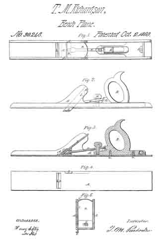
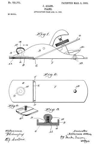
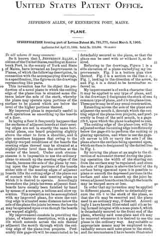
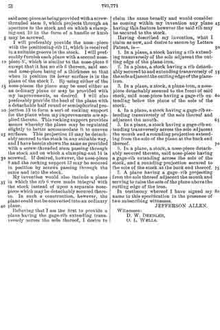
Referring to the drawings, Figure 1 is a side elevation of a plane embodying my improvements. Fig. 2 is a bottom plan view thereof. Fig. 3 is a section on the line x x, Fig. 1, looking in the direction of the arrow, and Fig. 4 is a detail to be hereinafter referred to.

My improvement is of such a character that it may be applied to any type of plane, and in the drawings 3 designates the stock of one common type of plane, and 4 is the plane-iron. These parts may be of any usual construction.

Extending across the sole of the plane and adjacent the mouth 5, through which the cutting edge of the plane-iron projects, and preferably in front of the said mouth, is a gage-rib 6, upon which the plane is adapted to rest.

The cutting edge of the plane-iron will be adjusted so that its cutting edge is sufficiently below the gage-rib to perform the cutting or planing operation, and when in use the gage-rib serves to lift or carry the sole 7 of the plane above the surface being operated upon, which surface is designated by the dotted line in Fig. 1.

By turning the plane at an angle to the direction of movement thereof during the planing operation the width of the shaving cut from the surface may be regulated, and since the sole of the plane is above the level of the surface being operated upon it is possible to plane or smooth the depressed portions in the surface and also to smooth up the joint between adjacent boards even though the boards may be warped more or less.

In order that my invention may be applied to different planes, I prefer to detachably secure the rib 6 to the stock of the plane, so that the rib may be removed and the plane used in an ordinary way, if desired. Accordingly I have herein illustrated said rib as being formed integral with a nose-piece 8, which is detachably secured to the front end of the plane, whereby said nose-plate and rib may be removed whenever it is desired to use the plane in the ordinary way. Any suitable or appropriate means may be employed to detachably secure said nose-piece to the stock, and for convenience I have herein illustrated said nose-piece as being provided with a screw-threaded stem 9, which projects through an aperture in the stock and on which a clamping-nut 10 in the form of a handle or knob may be screwed.

I will preferably provide the nose-piece with the positioning-rib 11, which is received in a suitable groove in the stock. I will preferably furnish each plane with a second nose-piece 8′, which is similar to the nose-piece 8 except that it has no rib 6 thereon, said second nose-piece being of a thickness so that when in position its lower surface is in the plane of the stock 7. By using either of the nose-pieces the plane may be used either as an ordinary plane or may be provided with my improvements, as desired. I will also preferably provide the heel of the plane with a detachable half round or semispherical projection 13 to form a sort of rocking support for the plane when my improvements are applied thereto. This rocking support provides means whereby the plane may be regulated slightly to better accommodate it to uneven surfaces. This projection 13 may be detachably secured to the stock in any suitable way, and I have herein shown the same as provided with a screw-threaded stem passing through the stock and on which a clamping-nut 14 is screwed. If desired, however, the nose-piece 8 and the rocking support 13 may be secured in position by screws passing through the same and into the stock.

My invention would also include a plane in which the rib (5 were made integral with the stock instead of upon a separate nose-piece which may be detachably secured thereto. In such a construction, however, the plane could not be converted into an ordinary plane.

Believing that I am the first to provide a plane having the gage-rib extending transversely across the sole thereof, I desire to claim the same broadly and would consider as coming within my invention any plane having this feature however the said rib may be secured to the stock.

Having described my invention, what I claim as new, and desire to secure by Letters Patent, is —

1. In a plane, a stock having a rib extending transversely of the sole adjacent the cutting edge of the plane-iron.

2. In a plane, a stock having a rib detachably secured to and extending transversely of the sole adjacent the cutting edge of the plane-iron.

3. In a plane, a stock, a plane-iron, a nose-piece detachably secured to the front of said stock, said nose-piece having a gage-rib extending below the plane of the sole of the stock.

4. In a plane, a stock having a gage-rib extending transversely of the sole thereof and adjacent the mouth.

5. In a plane, a stock having a gage-rib extending transversely across the sole adjacent the mouth and a rounding projection extending from the sole of the plane at the back end thereof.

6. In a plane, a stock, a nose-piece detachably secured thereto, said nose-piece having a gage-rib extending across the sole of the stock, and a rounding projection secured to the sole of the stock at the back end thereof.

7. A plane having a gage-rib projecting from the sole thereof adjacent the mouth and serving to raise the sole of the plane above the cutting edge of the iron.

In testimony whereof I have signed my name to this specification in the presence of two subscribing witnesses.

JEFFERSON ALLEN.

Witnesses:
D. W. DEEDLER,
O. L. WELLS.

No. 679,702 – Spokeshave (Walter D. Murray) (1901)

[paiddownloads id=”554″]679702


UNITED STATES PATENT OFFICE.

_________________

WALTER D. MURRAY, OF PORTLAND, MAINE, ASSIGNOR,
OF ONE-HALF TO WALTER ACKROYD, OF SAME PLACE.

SPOKESHAVE.

_________________

SPECIFICATION forming part of Letters Patent No. 679,702, dated July 30, 1901.
Application filed May 31, 1900. Serial No. 18,627. (No model.)

_________________

To all whom it may concern:

Be it known that l, WALTER D. MURRAY, a citizen of the United States, residing at Portland, in the county of Cumberland, in the State of Maine, have invented certain new and useful lmprovements in Spokeshaves, of which the following is a specification.

This invention relates to that class of wood-working planes known as spokeshaves.

One object of the invention is to provide a spokeshave with a detachable reversible sole-piece, either edge of which may be used to vary the form of the spokeshave to adapt it for either concave or straight work.

Another object of the invention is to provide simple and effective means for raising and lowering the blade, whereby either end thereof may be moved as desired independently of the other to seen re accuracy of adjustment.

Another object is to provide improved handles for the spokeshave for insuring a better grip and a steadier working tool.

Figure 1 of the accompanying drawings represents a front elevation of this spokeshave. Fig. 2 represents a rear elevation thereof. Fig. 3 represents a central transverse section on line 3 3 of Fig. 1. Fig. 4 represents a similar section with the sole-piece reversed. Fig. 5 represents a perspective view of the detachable sole-piece. Fig. 6 represents a perspective view of the blade or cutter. Fig. 7 represents a rear elevation of the stock, the detachable sole-piece being removed. Fig. 8 represents another form of connection between the blade and the adjusting-screws therefor. Fig. 9 represents an end view of the stock, one of the handles being shown in section on line 9 9 of Fig. 1.

The same reference numbers indicate corresponding parts in all the figures.

In the form of spokeshave illustrated in the accompanying drawings a body or stock 10, having handles 20 and 30 at its opposite ends, is recessed at its back to receive a detachable sole-piece 40. The recessing of the stock forms a rear bed for the blade and shoulders 11 and 12, against which the ends of the sole-piece 40 abut. These shoulders 11 and 12 are provided with screw-threaded sockets 13 and 14, adapted to receive headed screws 50 and 60, respectively, the object of which will be hereinafter described. This stock is provided with a slot 17, through which the shavings pass. Means are provided on the stock and sole-piece for adjusting the latter incorrect position, and these means may consist of lags on one part and notches in the other. When constructed as here shown, the stock 10 is provided at the opposite ends of its recessed bed with lugs 15 and 16, adapted to engage notches 41 and 42, formed in the opposite ends of the sole-piece 40, whereby the proper adjustment of the sole-piece is accomplished.

The detachable sole-piece 40 is preferably constructed with its opposite edges in different forms, being shown as provided with a flat edge 43 and with a rounded edge 44,and either edge may be used to vary the shape of the spokeshave, as desired, by reversing the sole-piece.

Suitable means are provided for fastening the detachable sole-piece to the stock. In the form shown this sole-piece 40 has a screw-threaded shank 45 extending at right angles from the center of its inner face. This shank 45 may consist of a screw passed through the sole-piece or it may form a part of a bolt, the sole-piece 40 constituting the head thereof. This shank or bolt 45 extends through a perforation 18 in the stock 10, and the outer end thereof is engaged by a thumb-nut 46, which firmly clamps the sole-piece to the stock.

A blade 70, having a longitudinal slot 71 therein, is disposed in the recessed portion of the stock; 10, between it and the sole-piece 40. The bolt 43 of the sole-piece passes through the slot 71 before entering the perforation 18 of the stock, and the screwing down of the thumb-nut 46 thereon clamps the knife 70 firmly in position between the stock and the sole-piece. This blade 70 is provided at its opposite ends, near its top, with means for engaging the adjusting-screws 50 and 60, respectively. In the form shown in Figs. 1 and 2 these means consist of notches 72 and 73. In the form shown in Fig. 8 they consist of lateral lugs 74, which engage grooved or double heads 51 and 61 on the adjusting-screws. This blade may be adjusted at any desired height by simply turning the screws in the direction desired, and either end thereof may be independently raised or lowered to secure accuracy of adjustment by raising or lowering the screw connected therewith. Concave recesses 21 and 31, disposed substantially in a vertical plane and at right angles to the sole of the shave, are formed at the ends of the stock and extend through the adjacent portions of the handles 20 and 30, on the rear side of the latter. These recesses serve as finger-rests for the index-fingers when the shave is grasped in the hands and afford a better grip for the operator and a steadier working tool.

Either the means for adjusting the blade, the peculiar form of handles, or the detachable sole-piece may be applied to any adaptable form of spokeshave.

I claim as my invention —

1. A spokeshave having a detachable rear sole-piece serving as a clamp for the blade.

2. A spokeshave having a detachable reversible rear sole-piece.

3. A spokeshave having a reversible rear sole-piece provided with edges of different forms.

4. A spokeshave provided with a reversible rear sole-piece having edges of different forms, one of said edges being flat and the other rounded.

5. A spokeshave comprising a recessed stock, a blade adapted to fit in said recess, a reversible sole-piece also adapted to fit in said recess behind said blade, said stock being provided with means for engaging said sole-piece, and means for securing the blade and sole-piece to the stock.

6. A spokeshave comprising a stock provided with a recess at its back, a reversible sole-piece, adapted to fit in said recess, interlocking means on said stock and sole-piece, a blade disposed between said stock and sole-piece, and means for securing said sole-piece and blade to said stock.

7. A spokeshave comprising a stock provided vvith a recess at its back and lugs at opposite ends of said recess, a reversible sole-piece adapted to fit in said recess and provided with notches adapted to engage said lugs, a blade disposed between said sole-piece and stock, and means for securing said blade and sole-piece to said stock.

8. A spokeshave comprising a recessed stock having a perforation therein, a detachable rear sole-piece having a bolt attached thereto and adapted to extend through said perforation, a thumb-nut adapted to screw on said bolt and fasten the sole-piece in position, and a blade clamped between said sole-piece and stock.

9. In a spokeshave the combination of a stock provided with a blade-bed and with screvv-sockets adjacent to opposite ends of said bed, a blade provided with notches at its opposite ends, means for clamping said blade to said bed, and adjusting-screws disposed in said sockets and provided with heads engaging said lateral notches.

10. A spokeshave comprising, a stock and handles extending from opposite ends thereof, vertical concave recesses being formed at the ends of the stock and adjacent portions of the handles on the rear side of the latter, which recesses serve as rests for the index-fingers when the shave is grasped by the hands.

WALTER D. MURRAY.

Witnesses:
ALICE H. SULIVAN,
JOSEPH E. DANAHER.

No. 65,562 – Improvement In Joiners’ Planes (Arthur Gray) (1867)

[paiddownloads id=”127″]65562


United States Patent Office.


ARTHUR GRAY, OF NAPLES, MAINE.

Letters Patent No. 65,562, dated June 11, 1867
_________________

IMPROVEMENT IN JOINERS’ PLANES.

_________________

The Schedule referred to in these Letters Patent and making part of the same.

_________________

TO ALL WHOM IT MAY OONCERN:

Be it known that I, ARTHUR GRAY, of Naples, in the county of Cumberland, and State of Maine, have invented a new and useful Improvement in Planes; and I hereby declare the following to be a full, clear, and exact description thereof, which will enable others to make and use my invention, reference being had to the accompanying drawings, forming part of this specification, in which —

Figure 1 shows a side sectional elevation of a plane-stock with my improvement exhibited therein.

Figure 2 represents a front view of the baclcircn and the method of its attachment to the plane-stock.

Figure 3 represents a view of the clamping-iron with its staple.

Figure 4 is an end view of the same showing the thumb-screw.

My invention has relation to a new and more convenient method of securing the cutting-iron in an ordinary plane-stock.

a shows what I will term the back-iron, secured to the stock by the screw b, and having the projection c, which is somewhat within the aperture in the stock for the insertion of the cutter. Behind this projection is the small space d. e is the cutter, which is placed between the back-iron and the clamp h. The clamp holds the cutter as follows: k is a staple on the clamp, which staple passes under the projection c, as seen in the drawing. m is a thumb-screw. The cutter is placed on the back-iron a; over the cutter is then put the clamp h, with its staple k under the projection c; then turn the thumb-screw, and as the screw presses off the upper end of the clamp from the cutter it will bind the cutter at the lower end and be confined by the staple passing under the projection. Thus a simple arrangement is provided for holding the cutter. By turning out the screw the pressure of the clamp is relieved and the cutter can be removed or changed in position.

I do not claim the combination of an adjustable cap and a screw for the purpose of securing the bit, which bit is held by two screws, one on each side of the bit, as is exhibited in Letters Patent No. 10,748 to W. S. Loughborough, April 4, 1854. Neither do I claim the combination of a movable friction-plate-separate from the plane-iron, with the throat of the plane-stock, thc said plate being secured by a screw passing through it and the plane-iron, as seen in Patent No. 20,615, to L. Bailey, June 22, 1858.

I also disclaim one or more bearers, a clamp-lever, and a thumb-cam, as a means of fixing the plane-iron, adjusting the same in the stock, and removing it therefrom, seen in another patent to said Bailey, No. 21,311, August 31, 1858. Neither do I claim the combination of a cap and screw and two trunnions, fitting in adjustable bearings to hold the cutting-iron of a plane, as set forth in Letters Patent to Seth C. Howes, No. 37,694, February 17, 1863. These devices are different from mine in not having the clamp h, with its staple k, to operate in combination with the thumb-screw m and projection c on the bottom of the back-iron to confine the cutter.

What I claim as my invention, and desire to secure by Letters Patent, is —

The combination of the projection e, on the back-iron, with the staple k and thumb-screw m on the clamp, when arranged as and for the purpose set forth.

ARTHUR GRAY.

Witnesses:
WM. HENRY CLIFFORD,
HENRY C. HOUSTON.

No. 63,948 – Improvement In Bench Planes (Charles H. Sawyer) (1867)

[paiddownloads id=”122″]63948


UNITED STATES PATENT OFFICE.

_________________

CHARLES H. SAWYER, OF HOLLIS, MAINE.

Letters Patent No. 63,948, dated April 16, 1867
_________________

IMPROVEMENT IN BENCH PLANES.

_________________

The Schedule referred to in these Letters Patent and making part of the same.

_________________

TO ALL WHOM IT MAY CONCERN:

Be it known that I, CHARLES H. SAWYER, of Hellis, in the county of York, and State of Maine, have invented a new and useful Improvement in Plane Stocks; and I do hereby declare the following to be a full, clear, and exact description thereof, which will enable others to make and use my invention, reference being had to the accompanying drawings, forming part of this specification, and in which —

Figure 1 shows a sectional elevation of my invention.

Figure 2, a plan of the top of the same.

Like letters refer to the same parts.

My invention has for its object the providing of a more convenient method than that now employed for adapting the bottom of a plane to curved surfaces, either concave or convex. In the accompanying drawings —

A shows a curved handle or stock, of the form indicated. B, fig. 1, shows a screw passing through the centre thereof and attached to the piece d. The cutting-iron, of the common form, is represented at e, and held in position by set-screws, fitting into slots therein and working into the inclined portion of the piece d. The set-screws and slots are seen at t s, fig. 2. The cutting-iron also passs through an aperture in the piece d. This is seen in fig. 1, at n. The piece d is firrnly and rigidly attached to the sheet m on its upper or inner side, at the centre thereof. The sheet m is secured to the ends of the curved handle or stock A by means of pivots or bolts, upon which it turns when bent. This is illustrated in fig. 1. The object of the piece d is to hold the end of the screw B and secure the cutting-iron in the manner above described. The space D is made in the curved stock or handle in order to admit of the insertion, adjustment, or removal of the cutting-iron e. Turning the screw B by means of the crank c, the sheet m is bent and retained in the positions indicated by the dotted lines in fig. 1, or at places intermediate between these two.

I am aware of the issue of Letters Patent to George F. Evans, but his invention is different from mine in several particulars.

I do not claim a graduating plane stock, combining, with a flexible sheet of metal for the bottom, two shanks and two set-screws for bending and retaining in position the same, and the sheet being secured at its centre to the middle of the stock, and bent at the ends thereof. I am also aware of a patent granted to the same which combines, with a bearing plate, two screws, two traversing nuts thereon, and two connecting-rods, the plate being attached to the stock, and being curved in a similar manner and at the same points as the one lirst mentioned. I do not claim such a method of imparting curvature to the plate, or the screws, traversing-nuts and connecting-rods, by which the curvature is given. My invention, further, differs from the subject of Letters Patent granted to the same, and numbered 41,983, which combines with a spring-face plate the construction of two connecting-rods and their receiving parts of the stock curved. The subject of Letters Patent granted to William A. Cole, June 6, 1848, consists of an ordinary plane with a convex face cut thereupon, to which, at the centre, is attached a metal plate, which is bent by means of slides attached to the ends thereof, said slides passing up against the front and back of the plane. I do not claim a device of this description.

The rejected application of Simon Williams, received and filed August 12,1862, describes a plane stock, wherein the metal plate is secured to the stock at the centre thereof and at the centre of the plate, and the plate is bent by means of adjusting screws turned to the right or left and bending the plate from its ends. This is dilferent from my invention in arrangement and operation, and I do not claim a device of this character. My invention is distinct from all of those above referred to, in having the flexible plate united at its ends to the ends of a curved stock, of the form delineated in the drawing, and, in both, receiving its curvature and being held at any desired curve by a vertical screw turned by a crank, and the screw being connected with the plate at the piece d.

What I claim as my invention, and desire to secure by Letters Patent, is —

The arrangement of the screw B, in combination with the joints or pivots by which the sheet m is connected at its ends to the ends of the handle or stock A, as and for the purposes herein described.

CHS. H. SAWYER.

Witnesses:
WILLIAM H. CLIFFORD,
HENRY C. HOUSTON.

No. 73,723 – Improvement In Spoke-Shaves (Seth T. Hutchins) (1868)

[paiddownloads id=”135″]73723


United States Patent Office.


SETH T. HUTCHINS, OF NORTH ANSON, MAINE, ASSIGNOR TO HORACE A.
LATHROP, OF SHARON, MASSACHUSETTS.

Letters Patent No. 73,723, dated January 28, 1868.
_________________

IMPROVEMENT IN SPOKE-SHAVES.

_________________

The Schedule referred to in these Letters Patent and making part of the same.

_________________

TO ALL PERSONS TO WHOM THESE PRESENTS MAY COME:

Be it known that I, SETH T. HUTCHINS, of North Anson, in the county of Somerset, and State of Maine, have invented a new and useful Improvement in Heel or Spoke-Shaves; and I do hereby declare the same to be fully described in the following specification, and represented in the accompanying drawings, of which —

Figure 1 is a. top view,
Figure 2 a bottom view, and
Figure 3 a side elevation of a spoke or heel-shave provided with my improvement.

In carrying out my invention, I not only make the adjustable throat-piece or gauge separate from two buttresses, so applied to the stock as to be capable of being moved or adjusted thereon, in order to properly adjust the throat-piece relatively to the knife or cutter, but I hinge the throat-piece to one of the said buttresses in a manner to enable the throat-piece to be turned aside or away from the knife, in order to allow the latter to be sharpened, as occasion may require; the adjusting abutments of the throat-piece remaining in the mean while undisturbed in their positions relatively to the stock. After the sharpening of the knife may have been effected, the restoration of the throat-piece to place against the abutment, away from which it was moved, can be accomplished, by simply turning the throat-piece down thereupon.

In the drawings, A denotes the stock, made in the usual form, and having two handles a a. B is the knife or cutter, fastened in or to the stock, C is the gauge, and D E its two adjustable abutments, each of the latter being held to the stock by means of a clamp-screw, b, going through a slot made in such abutment; the same being so as to enable the distance of the gauge or throat-piece C from the cutting-edge ofthe knife to be either increased or diminished, as circumstances may require. The gauge C is hinged, at or near one extremity, to the abutment E, and at its other end it bears against the other abutment, which is formed with a shoulder or bearing-surface for the gauge to rest on. This application of the gauge enables it to be moved from the abutment D into the position denoted by the dotted lines at G’ in fig. 3.

I do not claim merely applying the gauge to the stock, so as to be adjustable or capable of being adjusted nearer to or further from the knife, in order to either increase or diminish the chip-throat or passage between the knife and the gauge; but

1. I do claim the combination of the separate abutments D E, applied to the stock A, so as to be adjustable, in manner as described, with the gauge C hinged to one of such abutments, and being separate from the other, and to operate with respect to it substantially as explained.

2. I also claim the application of the gauge to its adjusting-devices, so as to be removable from them or either of them, and the knife, when the means of the adjustment of the gauge is held stationary relatively to the stock, as described.

SETH T. HUTCHINS.

Witnesses :
R. H. EDDY,
SAMUEL N. PIPER.

No. 86,295 – Improvement In Bench-Planes (Philander S. Foster) (1869)

[paiddownloads id=”147″]86295


United States Patent Office.


PHILANDER S. FOSTER, OF RICHMOND, MAINE.

Letters Patent No. 86,295, dated January 26, 1869.
_________________

IMPROVEMENT IN BENCH-PLANES.

_________________

The Schedule referred to in these Letters Patent and making part of the same.

_________________

To all whom it may concern:

Be it known that I, PHILANDER S. FOSTER, of Richmond, in the county of Sagadahoc, and State of Maine, have invented a new and valuable Improvement in Bench-Planes; and I do hereby declare that the following is a full, clear, and exact description of the construction and operation of the same, reference being had to the annexed drawings, making a part of this specification, and to the letters and figures of reference marked thereon.

Figure 1, of the drawings, is a side view of my bench-plane;
Figure 2 is a longitudinal section; and
Figure 3 is a cross-section of the same.

My invention relates to that class of bench-planes constructed partly of wood and partly of metal; and It consists in providing a remedy against the difficulty commonly called choking, by means that are more permanent and efficient than have heretofore been devised.

By my device, also, a wider bit may be used, and consequently a wider shaving be cut, than by the ordinary bench-planes.

The letter A, of the drawings, represents the removable and adjustable wooden front of the plane, and the letter B is the wooden rear thereof.

The part A is constructed with a slot in its middle, running lengthwise, as shown on fig. 2, adapted to hold and operate with the thumb-screw C. This slot is marked H on the drawings.

The letters D are metallic plates, adjusted respectively on each side of the wooden parts of the plane, in the manner shown on figs. 1 and 3.

That portion of these metallic side plates respectively which is adjusted forward of the bit and throat, is constructed in a bevelled form, as shown on fig. 3, and is adapted to corresponding grooves, out in the sides of the part A, in which grooves it is held securely and firmly by the thumb-screw C, in conjunction with its bevelled form so resting in its grooves.

The part A is cut off square at its rear end, leaving a small bevel at the point c, upon which the hammer may be used.

I sometimes also arrange metallic boxings in the grooves of the part A, adjusted to the plates D. These boxings will save the wear of the wood, and when properly oiled, will aid in the adjustment of said part to the bit of the plane.

The thumb-screw G passes through both plates D and the slot H, and serves as a means of tightening, loosening, and fastening the part A, at the will of the operator.

The letter E is the bit, and letter F is the wedge of the plane. These are adjusted in diagonal slots, formed in the inner sides of the plates D respectively, in the manner shown on fig. 2.

The fact that the bit and wedge are adjusted in plates of metal, instead of the wooden throat of the plane, as is usual, justifies the manufacturer in adapting a bit to the plane, that shall be wider, and consequently shall out a wider shaving than is prudent in planes wherein the bit is adjusted in wood only.

It will readily be perceived that by the upright formation of the rear end of part A, the plane is provided with a large open throat, which greatly lessens the danger of choking, and that in case such an event occurs, the chips in the throat may be easily loosened and removed, by moving the part A forward. This movement is effected by unscrewing the thumb-screw C, and striking a gentle blow with a hammer on the bevel c.

What I claim as my invention, and desire to secure by Letters Patent, is —

A bench-plane, having bevelled metallic side plates D, wooden sections A and B, slot H, and thumb-screw C, when the same are constructed and arranged as specified.

In testimony that I claim the above, I have hereunto subscribed my name, in the presence of two witnesses.

PHILANDER S. FOSTER.

Witnesses :
WM. S. HAGAR,
WM. H. STUART.

No. 67,671 – Improvement In Carpenters’ Planes (Russell Phillips) (1867)

[paiddownloads id=”132″]67671


United States Patent Office.


RUSSELL PHILLIPS, OF GARDINER, MAINE, ASSIGNOR TO HIMSELF AND NATHAN WESTON.

Letters Patent No. 67,671, dated August 13, 1867.
_________________

IMPROVEMENT IN CARPENTERS’ PLANES.

_________________

The Schedule referred to in these Letters Patent and making part of the same.

_________________

TO ALL WHOM IT MAY CONCERN:

Be it known that I, RUSSELL PHILLIPS, of Gardiner, in the county of Kennebec, and State of Maine, have invented a new and useful Improved Joiners’ Plough ; and I hereby declare the following to be a full, clear, and exact description thereof, which will enable others to make and use my invention, reference being had to the accompanying drawings, forming part of this specification, in which —

Figure 1 shows a side elevation of my invention.
Figure 2, a portion of the top of the horizontal arm, having the graduated scale.
Figure 3 is an end view of my invention, and a view of the top of the end and slides.
Figure 4, a view of a portion of the reverse side of fig. 1.
Figure 5, an edge view of the iron or cutter.
Figure 6, a portion of the adjustable guide or gauge.

Same letters show like parts.

My invention has relation to that tool employed by certain mechanics, joiners, &c., called a plough, and consists in certain improvements thereupon, which may be separately or conjointly used.

I will now describe in detail the different improvements combined in my invention. a shows the groove in which the iron or cutter is placed. It is there secured by means of the clamp b and slide c. Fig. 4 shows the manner in which the slide c is held in place, being by means of a slot and a lip, d, on the side opposite to the one shown in fig. 1. The lip d overlaps the edge of the slot, shown in fig. 4. e is a small projection, to rest against the end of the cutter, so that its edge shall not become dulled by striking or touching any part of the stock. The cutter is fully described hereafter. The cutter, being placed in the groove a, is secured as follows:

As illustrated in fig. 4, the slot in which the slide c moves is curved, so that when the slide is pressed downward, or toward the bottom of the plough, the clamp b is pressed upon the cutter; and when the slide is moved up, the clamp is released or loosened, and its pressure upon the cutter taken away. The clamp b swings on its pivot f. Place the cutter in the groove a, press the slide downward, thus forcing the clamp b upon the cutter, and the cutter is held in place. In this method there is this advantage: With the old form of fastening the cutter or iron, when the wedge that holds it is driven inward by the blow of the hammer or other implement the entrance of the wedge within the stock carries with it, somewhat, the cutter, so that when the cutter has once been adjusted as the mechanic desires, it is made to project further, by being carried inward with the wedge which holds it. Besides this inconvenience, it is difficult to adjust readily. With my invention, the cutter is placed in the desired position, so as to cut into the lumber the desired depth, and can then be immediately fastened by pressing the slide c downward. Moreover, as the clamp b does not slide at all, but simply pushes against the cutter, the cutter is not moved in the least from the desired position, but remains as placed by the user. g, fig. 5, shows the iron or cutter; this has a cutting edge at both ends. These two can be made of different sizes and widths, as seen in the drawing, so as to cut grooves or channels of different widths and sizes. It has a groove, h, to fit over the edge i, to aid in holding it securely. The end of the cutter not employed passes into the recess behind the projection e, and thus its edge is kept from injury till wanted. j is a thumb-piece, for convenience in placing the cutter in its place, and to strike upon with a hammer to move the cutter up or down slightly when it is held by the clamp b. k k are the cutting edges of the iron. l l l l show points projecting beyond the edges k k, which enable the iron to do its work not only with but also across the grain of the wood. These points are sharp, and cut the fibres of the wood before they are reached by the edges k, and thus prevent tearing or breaking out of the work. A shows the single horizontal arm employed in my invention, and upon which the guide or gauge B slides. Upon its top is a channel, with the graduated scale, so that the distance that the gauge is set from the cutter g can be accurately adjusted. Upon this there is no screw-thread, as upon the old form of plough, and, as before remarked, I use but a single arm. This admits of a much easier, more accurate, and readier arrangement for use. The gauge or guide B is made of metal, and has a portion, n, which turns on a hinge, and can be lifted up so as to leave the space o. The object of this will be hereafter described. p are slides, one on each side of the stock of the plough, near the forward end, moving in recesses, and held at any point by the thumb-screw q, which slides in the slot r, shown in fig. 1 by the dotted lines. These slides have at their bottoms the horizontal plates s, one on each side of the plate t. The combination of these devices forms a gauge by which the degree of the penetration of the cutter g into the wood can be governed. By loosening the thumb-screw q, the slides may be raised or lowered, as desired, on either side of t, (see fig. 3.) and, as seen in fig. 1, the cutter is intended to rest against the side of t, so that the depth of the groove to be cut can thus be exactly controlled, and measured by the graduated scale x on the end of the stock, (see fig. 3.) Most of the work to be done by this tool is near the edge of boards or other wood. In such a ease it might happen that the gauge or guide B could not be brought sufficiently near the plate t on account of the projection of the horizontal plates s. This I obviate by the arrangement shown in fig. 6, before described. When the trap an is lifted, as seen in the drawing, the gauge B can be brought quite close to t, one of the plates s entering the space o. In use, one hand of the mechanic rests upon the guide B, where a wooden handle is supplied. The handle upon the stock is seen at D, being placed at the end of the stock, and lower down than is ordinary, with the view that the force applied to the tool is all or nearly all exerted in a horizontal direction, which lessens the labor of using the plough, and makes it more effective. The handle is secured by the removable bolt u, so that if broken the handle can easily be taken off and another substituted. All the parts described, except the arm A, handle D, and a portion of the guide B, are made of metal, which makes the whole tool cheaper, less cumbersome, stronger, and more convenient. The clamp b being made of metal, quite smooth, and slightly rounded, enables the tool to clear itself quite readily of the shavings made in using it. The method of confining the gauge or guide B at any desired point is by the use of the thumb-screw m.

What I claim as my invention, and desire to secure by Letters Patent, is —

1. The reversible cutter shown in fig. 5, as and for the purposes specified.

2. The arrangement of the two slides p p, thumb-screw q, slot r, plates s s, graduated scale x, and plate t, as and for the purposes set forth.

RUSSELL PHILLIPS.

Witnesses:
WILLIAM HENRY CLIFFORD,
HENRY C. HOUSTON.

No. 30,248 – Device For Securing Plane Bits (Theodore M. Richardson) (1860)

[paiddownloads id=”90″]30248


UNITED STATES PATENT OFFICE.

_________________

T. M. RICHARDSON, OF STOCKTON, MAINE.

DEVICE FOR SECURING PLANE-BITS.

_________________

Specification of Letters Patent No. 30,248, dated October 2, 1860.

_________________

To all whom it may concern:

Be it known that I, THEODORE M. RICHARDSON, of Stockton, in the county of Waldo and State of Maine, have invented an Improved Joiner’s Plane; and I do hereby declare that the same is fully described in the following specification and represented in the accompanying drawings, of which —

Figure 1, is a top view; Fig. 2, a side view; Fig. 3, a longitudinal section, and Fig. 4, an underside view of it. Fig. 5, exhibits a transverse section taken through the middle of the slider arranged in the side of the plane stock.

In these drawings A, denotes the stock, and, B, the handle thereof, the two being formed of metal or other suitable material and secured together by screws, a, a. The throat, b, of the plane stock is furnished with a stationary cap iron or cutter bearing, C, against the underside of which the cutter or plane iron, D, is arranged as shown in the drawings. The said plane iron is forced or clamped against the cap iron, C, by means of a wedge, E, a pitman, F, an inclined plane G, and a screw H, arranged relatively to each, the plane stock, the cutter and handle as shown in the drawings, that is to say, the wedge, E, is placed between the cutter and the base plate of the stock, while the inclined plane, G, is disposed in front of the handle and the pitman is made to extend from the inclined plane to the wedge and has the screw, H, carried through it and screwed into the front part of the base of the handle. By screwing down the said screw, the pitman will be forced down the inclined plane and by the latter will be driven forward against the wedge and thereby cause the said wedge to force the cutter or plane iron hard up against the bearing or cap iron, C. A slider, I, is arranged in the side of the plane stock and so as to slide into the recess, K, formed therein, and parallel or nearly so to the cutter. When the said slider is made to extend out of the socket or recess and beyond the lower face of the plane stock as shown in the drawings, it will serve as a guide for a workman in planing a “glue joint” or one surface at right angles to another the slider serving, in this respect, the purpose of an ordinary carpenter’s square, as its inner face, when the slider is extended shall stand at ip right angle with the underside of the stock.

In rear of the handle and in its base, I arrange a small glass spirit level L, and so as to stand transversely with respect to the plane stock, in other words at right angles with its sides, the said level being disposed as shown in Figs. 1 and 3. By this arrangement of the level it is covered and protected by the wrist of a workman while his hand may be grasping the handle, B, and thus the level is not so likely to becoine broken as would be the case were it arranged at the opposite end of the stock and in advance of the handle. My arrangement of the parts for holding the plane iron in place enables such iron to be removed and replaced with respect to the cap iron without requiring the aid of a screw driver or hammer.

I claim —

The arrangement of the clamp wedge E, the pitman, F, the inclined plane, G, and the screw, H, with the plane iron D, its cap bearing, C, and the stock A, substantially as described.

T. M. RICHARDSON.

Wtitnesses:
HENRY S. STAPLES,
ALEXANDER STAPLES, Jr.

No. 34,248 – Improvement In Plane Stocks (George Franklin Evans) (1862)

[paiddownloads id=”95″]34248


UNITED STATES PATENT OFFICE.

_________________

GEORGE F. EVANS, OF NORWAY, MAINE.

IMPROVEMENT IN PLANE-STOCKS.

_________________

Specification forming part of Letters Patent No. 34,248, dated January 28, 1862.

_________________

To all whom it may concern:

Be it known that I, GEORGE F. EVANS, of Norway, in the county of Oxford and State of Maine, have invented a new and useful or Improved Plane; and I do hereby declare the same to be fully described in the following specification, and represented in the accompanying drawings, of which —

Figure 1 denotes a side elevation; Fig. 2, a longitudinal section of my said plane prepared to operate upon a curved surface having a great degree of curvature; Fig. 3, a side elevation of such plane as prepared to plane on a surface having the slightest curvature; Fig. 4, a horizontal section of the plane, taken through the adjusting-screws and traversing nuts. Fig. 5 is a bottom view of the plane.

The object I had in view in making my invention was to supply a want which has long existed, viz: an instrument which would plane or smoothen any circular concave surface evenly and exactly.

The nature of my invention consists in an improved plane so constructed that its bearing surface or face may be readily adjusted to conform to circular surfaces of different degrees of curvature, whereby such circular parts may be as easily and smoothly planed as a plane surface can be by the ordinary straight-faced plane.

In the drawings, A denotes the stock or body of the plane, the same having a throat or shaving passage B formed vertically through it. In the said passage or throat the plane iron or cutter is secured by means of a wedge C and a cap-plate D in the ordinary manner. Instead of forming the lower face of the stock A as a straight or plane surface,I cause the same to be curved upward in manner as shown in the drawings.

To the lower face of the stock I fasten a flat steel plate E by means of two screws a a, and a bifurcated bar b, whose lower ends extend through the said plate and are riveted thereto, while its other end is secured by means of a screw to the rear part of the throat-passage.

Within the two ends of the stock A and extending longitudinally therein I form two chambers c c’ for reception of two screws G G’ and two traversing nuts H H’, the said screws being supported in stationary bearings d d’, arranged in each end of each of the said chambers c c’. Each of the screws G carries a traversing nut H of a rectangular shape, the said nut being jointed or pivoted at its lower edge with a connecting-rod I, whose lower end is in turnconnected or jointed to the plate E’, the length of the connecting-rods being suoh as to allow the plate E, when the nuts H H’ are at their greatest point of outward extension, to assume or stand in or nearly in a horizontal plane. The screws G or G’ have no longitudinal movement, but are free to revolve on their axes, so as to cause the nuts H H’ to traverse the whole length of their chambers c c’.

A plane constructed in the above-described improved manner can be readily adapted or adjusted to plane or reduce any circular concave piece of wood by simply turning the two screws G G’ in the proper direction.

Having described my invention, I claim —

My improved plane, having its body A, its bearing-plate E, its screws G G’, traversing nuts H H’, and connecting-rods I I, constructed and arranged in relation to each other and so as to operate together, as set forth.

GEORGE F. EVANS.

Witnesses:
LEVI WHITMAN,
RICHARD EVANS.

No. 41,983 – Improvement In Plane Stocks (George Franklin Evans) (1864)

[paiddownloads id=”102″]41893


UNITED STATES PATENT OFFICE.

_________________

GEORGE FRANKLIN EVANS, OF NORWAY, MAINE.

IMPROVEMENT IN PLANE-STOCKS.

_________________

Specification forming part of Letters Patent No. 41,983, dated March 22, 1864.

_________________

To all whom it may concern:

Be it known that I, GEORGE FRANKLIN EVANS, of Norway, in the county of Oxford and State of Maine, have made new and important Improvements in the Plane that was patented January 28, 1862; and I do hereby declare the same to be fully described in the following specification, and represented in the accompanying drawings, of which —

Figure 1 is a plan. Fig. 2 is a longitudinal elevation with the face-plate in a straight position. Fig. 3 is a longitudinal vertical section with the face-plate in a convex position. Fig. 4 is a longitudinal elevation with the face-plate in a concave position or reversed from that in Fig. 3. Fig. 5 is a longitudinal elevation of the rabbet and grooving plane with the face-plate in a straight position.

The nature of my improvement consists not only in the manner of making the stock, but in the combination of the arms which connect the ends ofthe spring face-plate to the stock, the same admitting the spring face-plate to be curved either ccnvexly or concavely on its outer surface. These planes are so constructed that they may be more readily adjusted to conform to concave and convex surfaces of diiferent degrees of curvature, whereby such circular parts may be as easily and smoothly planed, grooved, or rabbeted as a plane surface can be by the ordinary straight taced plane.

In the drawings, A is the stock or body of the plane, the same having a throat or shaving passage, B, formed vertically through it, (horizontally in the grooving-plane, Fig. 5.) In the said passage is the plane-iron, which is secured by the leverchip C and the thumb-screw D.

Instead of forming the lower face of the stock A as a straight plane, I cause the same to be curved upward and downward, in the manner as shown in the drawings. To the lower face of the stock I fasten on a flat steel plate by means of ten steel rivets, E E, on the lower part of the throat-passage — five rivets on the forward part and five rivets on the rear part of the throat-passage, as shown in Fig. 1.

Within the two ends of the stock A pass the connecting-rods F F in the form of a segment of a circle. The lower end of each connecting-rod has a hinge-joint, and is received by a socket or hollow pipe with solid ends, which pipe or socket is fastened to the ends of the steel plate G G by means of two steel rivets, I I. In each end of the stock A is a set-screw, H,which holds the connecting-rods F F in position, as shown in Figs. 2 and 4.

A plane constructed on the above-described improved manner can be readily adjusted to plane any circular, concave, or convex piece of wood; also to groove or rabbet the same by simply bending the plate G to the desired position and securing it by means of the connecting-rods F F and the set-screws J J.

From the above and by inspection of the drawings it will be perceived that my improved plane has its stock formed with two curved ends or projections extending from the part B, which hold the plane-iron, and so adapted to receive the curved arms F F as to allow them to play or move in curved paths both toward and away Ironi the said part B. Now, this mode of making the plane-stock not only enables the spring face-plate to be bent either into a convex or concave form, but it renders the curved ends or projections very convenient as handles by which the plane may be held and operated. Furthermore, they not only give to the connections F F a long range of motion, but keep their upper ends always within the stock when the face-plate is convex on its outer surface, there being no projection of the connections F F above the top surface of the plane-stock when the G is bent to its extreme position, as shown in Fig. 3.

What, therefore, I claim as my invention or improvement in the plane made with the spring face-plate is —

The construction of the connecting-rods F F and their receiving parts of the stock, curved substantially in the manner and so as to operate together as specified.

GEORGE FRANKLIN EVANS.

Witnesses:
HENRY UPTON,
C. C. SANDERSON.