No. 269,968 – Bench Plane (Jacob Siegley) (1883)
UNITED STATES PATENT OFFICE.
_________________
JACOB SIEGLEY, OF NEW YORK, N. Y.
BENCH-PLANE.
_________________
SPECIFICATION forming part of Letters Patent No. 269,968, dated January 2, 1883.
Application filed May 22, 1882.
_________________
To all whom it may concern:
Be it known that I, JACOB SIEGLEY, of the city, county, and State of New York, have invented certain new and useful Improvements in Bench-Planes, of which the following is a specifcation.
This invention has reference to certain improvements in bench-planes, for which Letters Patent of the United States have been granted to me heretofore, which Letters Patent bear date, respectively, July 1,1879, and August 16, 1881, and are numbered 216,979 and 245,752, the improvements being designed with a view to lock the cutting-tool or plow in a more reliable manner and facilitate the forward feeding and adjusting of the same.
The invention consists of a bench-plane, the stock of which is provided with an inclined cutting-tool or plow, the upper surface of which is laterally grooved or serrated, to be engaged by a wedge-shaped locking-block having a correspondingly-grooved bottom, said block being secured against an inclined cheek of the stock by a lateral screw-post and clamp-nut, and moved forward by a longitudinal set-screw of the wedge shaped block, so as to raise or lower the plow in the stock.
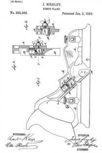
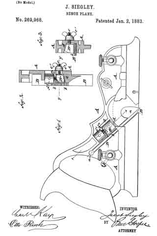
In the accompanying drawings, Figure 1 represents a side elevation of my improved bench-plane, and Figs. 2 and 3 are respectively a detail section on line x x, Fig. 1, and a vertical transverse section on line y y, Fig. 2.
Similar letters of reference indicate corresponding parts.
Referring to the drawings, A represents the stock of my improved bench-plane, which is made of cast-iron or other suitable metal, and with a handle of the usual form at the rear end. The middle part of the stock A is provided with an inclined recess, a, the lower surface of which forms the bearing-surface for the detachable plow or other cutting-tool B. The cutting-tool B is provided at its upper surface and near its middle portion with transverse grooves b b, which are engaged by the grooved or serrated bottom of a wedge-shaped locking-block, B’, the tapering top and side of which are guided along flaring cheeks d d of the stock A. The wedge-shaped block B’ is adjusted by means of a lateral screw-post, e, that is secured to the block and passed through a recess of the stock A, the block being tightly clamped to the stock and cutting-tool by a screw-nut, e’, as shown, respectively, in Figs. 2 and 3. The wedge-shaped block B’ is further arranged with a set-screw, j, that engages an interiorly-threaded socket of the wedge-shaped block B’, the set-screw f being arranged parallel to the cutting-tool or plow B, and provided with a head, f’, having socket-holes for inserting a suitable lever-pin, whereby the screw may be turned in one or the other direction. The head f’ of the screw f bears against a shoulder, f2, of the stock A, so that on turning the head the wedge-shaped block B’, and consequently the cutting-tool or plow B, is set higher or lower in the stock, as required for the proper setting of the tool. The wedge-shaped block B’ has to be of somewhat less length than the distance between the flaring front cheek, d, and the shoulder f2, so as to provide a certain play for the adjustment of the block and cutting-tool after the same has been placed in position in the recess of the stock. For adjusting the cutting-tool B the clamping-nut is first loosened and the cutting-tool adjusted so that its cutting-edge projects below the bottom surface of the stock A. The locking-block B’ is now clamped tightly to the grooved portion of the cutting-tool B, and, finally, the tool adjusted forward or back by means of the adjusting set-screw f so that the proper length projects below the bottom surface of the stock. In this manner a reliable locking device tor the cutting-tools of bench-planes is obtained, and a means whereby the cutting-tool may be accurately adjusted from time to time, as required by the work and the gradual wear of the tool.
Having thus described my invention, I claim as new and desire to secure by Letters Patent —
1. In a bench-plane, the combination of a stock having flaring cheeks, a plow or cutting-tool having transverse grooves at its upper surface, a wedge-shaped locking-block having a grooved bottom, means for clamping the block tightly to the cutting-tool. and means for longitudinally adjusting the locking-block and cutting-tool, substantially as and for the purpose set forth.
2. In a bench-plane, the combination of the stock: A, having an inclined recess, a, flaring cheeks d d2, and shoulder f2, a plow or cutting-tool, B, having transverse grooves b b, a, wedge shaped locking-block, B’, having a grooved bottom, a, lateral screw-post, e, and clamp-nut e’, and a longitudinal set-screw, f’, all substantially set forth.
In testimony that I claim the foregoing as my invention I have signed my name in presence of two subscribing witnesses.
JACOB SIEGLEY
Witnesses:
PAUL GOEPEL,
SIDNEY MANN.

