No. 33,240 – Improvement In Planes (Abraham S. Cross) (1861)

[paiddownloads id=”93″]33240


UNITED STATES PATENT OFFICE.

_________________

ABRAHAM S. CROSS, OF RIPON, WISCONSIN.

IMPROVEMENT IN PLANES.

_________________

Specification forming part of Letters Patent No. 33,240, dated September 10, 1861.

_________________

To all whom it may concern:

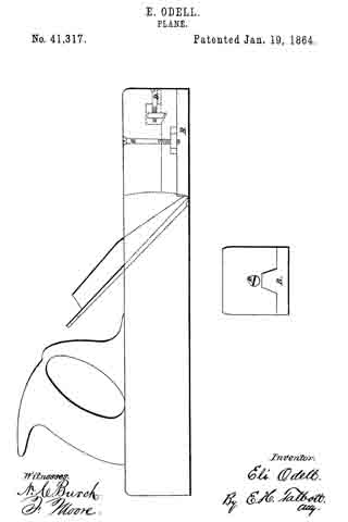
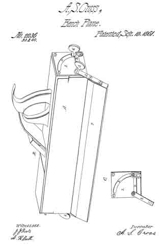
Be it known that I, ABRAHAM S. CROSS, of Ripon, in the county of Fond du Lac and State of Wisconsin, have invented certain new and useful Improvements in Joiners’ Planes; and I do hereby declare that the following is a full, clear, and exact description of the same, reference being had to the accompanying drawing, and to the letters of reference marked thereon.

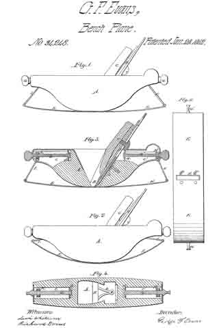
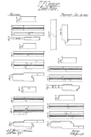
In the annexed drawing, making part of this specification, A represents the body or stock of the plane, which is constructed in any of the known and usual ways. Upon each end of this stock is secured a plate 1, made of metal. These plates are both provided with circular-formed slots 3.

2 represents a bent arm, which is secured through its angular portion to the plane-stock by means of a screw 5. This arm turns upon the screw 5 as a center. When the screw is tightened the arm is made fast to the stock. One end of the arm is provided with a slot 4. A set-screw 6 passes through this slot and also through the slot 3. This screw 6 is so arranged as to allow the arm 2 to partially revolve when necessary and also to station it at any desired point. By means of the slot 4. the arm 2 is enabled to turn farther than it could otherwise do, as is clearly evident, and is thus enabled, with the help of the guide 7, to form a miter.

7 is the guide upon the end of the arm for holding the plane to its position at any angle at which it is set. This guide, together with the arm 2, may be removed at any time by simply removing the screws 5 and 6, thus making the common plane of it. The end plates with this attachment may be used upon any common joiner’s plane.

I claim —

1. The combination of the arm 2, provided with slot 4, with the slot in plate 1 for the purpose of extending the slot 3 to form a miter.

2. The combination of the guide 7, the arm 2, the slotted end plates 1, and the screws 5 and 6, when the several parts are constructed and arranged in the manner herein set forth.

ABRAHAM S. CROSS.

In presence of —
A. H. BOOTH,
E. G. GRANT.

No. 34,248 – Improvement In Plane Stocks (George Franklin Evans) (1862)

[paiddownloads id=”95″]34248


UNITED STATES PATENT OFFICE.

_________________

GEORGE F. EVANS, OF NORWAY, MAINE.

IMPROVEMENT IN PLANE-STOCKS.

_________________

Specification forming part of Letters Patent No. 34,248, dated January 28, 1862.

_________________

To all whom it may concern:

Be it known that I, GEORGE F. EVANS, of Norway, in the county of Oxford and State of Maine, have invented a new and useful or Improved Plane; and I do hereby declare the same to be fully described in the following specification, and represented in the accompanying drawings, of which —

Figure 1 denotes a side elevation; Fig. 2, a longitudinal section of my said plane prepared to operate upon a curved surface having a great degree of curvature; Fig. 3, a side elevation of such plane as prepared to plane on a surface having the slightest curvature; Fig. 4, a horizontal section of the plane, taken through the adjusting-screws and traversing nuts. Fig. 5 is a bottom view of the plane.

The object I had in view in making my invention was to supply a want which has long existed, viz: an instrument which would plane or smoothen any circular concave surface evenly and exactly.

The nature of my invention consists in an improved plane so constructed that its bearing surface or face may be readily adjusted to conform to circular surfaces of different degrees of curvature, whereby such circular parts may be as easily and smoothly planed as a plane surface can be by the ordinary straight-faced plane.

In the drawings, A denotes the stock or body of the plane, the same having a throat or shaving passage B formed vertically through it. In the said passage or throat the plane iron or cutter is secured by means of a wedge C and a cap-plate D in the ordinary manner. Instead of forming the lower face of the stock A as a straight or plane surface,I cause the same to be curved upward in manner as shown in the drawings.

To the lower face of the stock I fasten a flat steel plate E by means of two screws a a, and a bifurcated bar b, whose lower ends extend through the said plate and are riveted thereto, while its other end is secured by means of a screw to the rear part of the throat-passage.

Within the two ends of the stock A and extending longitudinally therein I form two chambers c c’ for reception of two screws G G’ and two traversing nuts H H’, the said screws being supported in stationary bearings d d’, arranged in each end of each of the said chambers c c’. Each of the screws G carries a traversing nut H of a rectangular shape, the said nut being jointed or pivoted at its lower edge with a connecting-rod I, whose lower end is in turnconnected or jointed to the plate E’, the length of the connecting-rods being suoh as to allow the plate E, when the nuts H H’ are at their greatest point of outward extension, to assume or stand in or nearly in a horizontal plane. The screws G or G’ have no longitudinal movement, but are free to revolve on their axes, so as to cause the nuts H H’ to traverse the whole length of their chambers c c’.

A plane constructed in the above-described improved manner can be readily adapted or adjusted to plane or reduce any circular concave piece of wood by simply turning the two screws G G’ in the proper direction.

Having described my invention, I claim —

My improved plane, having its body A, its bearing-plate E, its screws G G’, traversing nuts H H’, and connecting-rods I I, constructed and arranged in relation to each other and so as to operate together, as set forth.

GEORGE F. EVANS.

Witnesses:
LEVI WHITMAN,
RICHARD EVANS.

No. 35,719 – Improvement In Planes (Joseph Vendrand) (1862)

[paiddownloads id=”96″]35719


UNITED STATES PATENT OFFICE.

_________________

JOSEPH VENDRAND, OF PARIS, FRANCE.

IMPROVEMENT IN PLANES.

_________________

Specification forming part of Letters Patent No. 35,719, dated June 24, 1862.

_________________

To all whom it may concern:

Be it known that I, JOSEPH VENDRAND, of Paris, in the Empire of France, have invented certain new and useful Improvements in Planes; and I do hereby declare that the following is a full and exact description thereof.

All persons accustomed to the use of hand-planes are acquainted with the difficulty of properly adjusting the plane-iron in the stock in such a manner as to give the perfect parallelism which must exist between the face of the plane and the edge of the iron, and to secure the perfect nicety of adjustment of the projection of the edge beyond the face of the plane, which is necessary for fine work.

The improvements which I have invented and for which I desire to obtain a patent obviate perfectly the inconveniences above stated.

They consist in the construction and arrangement of parts, hereinafter described, by which an additional regulation is attained, so as to preserve the parallel position of the cutting-edge with reference to the face of the plane, while it is raised or lowered by the adjusting-screw to adapt it to cut the proper thickness of shaving, and also in the construction and arrangement of parts for securing the plane-iron in position.

The regulator by which the plane iron is adjusted to the proper depth of cut, which is operated simply by the hand, does not sensibly complicate the plane, and it permits the regulation of the projection of the iron to the utmost nicety that may be desired.

For the purpose of facilitating the operation of the plane for persons who are not much habituated to its management, I in some cases cut away the wood of each of its sides in such a manner as to produce grooves sufficiently deep to permit it to be easily grasped when the workmen desires to raise the tool or to direct it to his fancy with greater ease.

The accompanying drawings will give a clear idea of the nature ofthe invention.

Figure 1 is a longitudinal vertical section of a plane constructed with my improvements. Fig. 2 is a plan of the same. Fig. 3 is a transverse vertical section showing the parts toward the rear end of the plane from the line 1 2, the plane-iron and cap being removed to give an unobstructed view of other parts.

The iron A is controlled by the tenon a, which is a part of the nut B, sliding on the support C, by means ofthe screw V, which is operated by the milled head v. The tenon a fits into a mortise, It, which is made transversely in the iron A and of sufficient length to allow the necessary lateral adjustment of the upper end of the iron to bring the edge parallel with the face of the plane.

The iron, regulated by means of the screw V, is retained in the position given it by the movable stirrup E, which oscillates on an axis, e’, in the fixed support C. For that purpose the stirrup or frame E is separated or divided in the lower part into two branches, upon which two parallel ears, E’, are formed, which ears take hold of the flange of the nut a’, Fig.
4, which binds the iron and cap together.

The stirrup E is operated to secure the plane-iron to its seat by means of screw e, which passes through the socket or eye E2, and rests at its lower end upon the head of a screw sunk in the top of the plane. By turning the screw e down upon this support the eye E2 is raised and the ears E’ conseqnently forced back so as to draw the plane-iron and cap down firmly against the wood, which supports them and retains them securely in position. In adjusting the iron it may be proper to slightly loosen the screw e to allow the iron to be moved with greater ease. The adjustment is then made by means of the screw V to any desired exactness. The first adjustment to be made, however, upon inserting the plane-iron is to get the edge perfectly parallel with the face of the plane, which the mode of connecting the plane-iron to the adjusting-screw by the elongated mortise and tenon on the nut in which the adjusting-screw works enables the operator to do satisfactorily. This adjustment once made, the plane-iron may be moved up and down without disturbing the parallelism of the edge with the face ofthe plane.

When it is desired to remove the plane-iron, the screw e should be turned back about three revolutions, which will give the necessary play between the ears E’ and the nut a’ to allow such removal.

The improvements which I have described may be applied with equal advantage to planes of every size and to planes for working rabbets, moldings, and cavettos.

I am aware that planes have been constructed in which the cutting-iron has been adjusted by raising and lowering it through the agency of a screw, without any means of lateral adjustment to secure perfect parallelism between the edge of the cutter and the face of the plane. I am also aware that a patent was granted to Thomas D. Worrall, August 4, 1857, in which a flange is represented attached to the plane iron, upon which flange a lever, hung upon an axis near the top of the stock and operated by a screw from the rear, is intended to operate to secure the cutter in position. The arrangement of parts is, however, different from that I have described, and involves objections in practical use which my invention avoids. The attachment of the flange adds expense and complication to the plane, While in my invention the nut which secures the cap to the cutter also furnishes the means of grasping and securing it in position. The arrangement of the screw for fastening the plane-iron back of the lever upon which it operates to secure said iron, as in Worrall’s plane, is also objectionable, because it involves complication of parts, and because it brings the head of the screw in the way of the right hand of the workman when operating the plane. These objections are avoided by my invention.

I claim–

1. The combination, with the plane-iron A, provided with mortises R, as described, of the adjusting-screw V, sliding block B, and tenon a, the said tenon and mortise being relatively so constructed as to allow the iron sufheient lateral play to permit the perfect adjustment ofthe edge parallel to the face of the plane, as set forth.

2. The combination of the nut a, which secures the cap to the cutting-iron, with the lever E and ears E’ E’, as and for the purpose set forth.

3. The arrangement of the lever E and screw e, as described — that is to say, in such a manner that the screw shall take its point of support upon the top of the plane and, extending up through the nut E2, terminate in a head for operating above the lever E, as set forth, instead of behind it, where it would be in the way of the operator.

In testimony whereof I have signed my name to this specification before two subscribing witnesses.

J. VENDRAND.

Witnesses:
E. RICHARD,
GEO. HUTTON.

No. 37,694 – Improvement In Bench Planes (Seth C. Howes) (1863)

[paiddownloads id=”97″]37694


UNITED STATES PATENT OFFICE.

_________________

SETH C. HOWES, OF SOUTH CHATHAM, MASSACHUSETTS.

IMPROVEMENT IN BENCH-PLANES.

_________________

Specification of Letters Patent No. 37,694, dated February 17, 1863.

_________________

To all whom it may concern:

Be it known that I, SETH C. HOWES, of South Chatham, in the county of Barnstable and State of Massachusetts, have invented a new and useful Improvement in Bench-Planes, such as are used by joiners and other artisans in wood; and I do hereby declare that the following is a full, clear, and exact description of the same, reference being had to the accompanying drawings, making part of this specification, in which —

Figure 1 is a vertical section of my invention, taken in the line x, x, Fig. 2. Fig. 2 is a plan or top view of the same. Figs. 3 and 4 are detached views of parts pertaining to the same.

Similar letters of reference indicate corresponding parts in the several figures.

This invention relates to an improvement in that class of planes which are commonly termed “bench-planes,” comprising the fore-plane, smoothing-plane, jack-plane, jointer, &c.

The invention consists in a novel and improved mode of adjusting the plane-iron to regulate the depth of the cut of the same, in connection with an adjustable cap, all being constructed and arranged in such a manner that the plane-iron may be “set” with the greatest facility and firmly retained in position by the adjustment simply of the cap to the plane-iron, after the latter is set, and the cap also rendered capable of being adjusted to compensate for the wear of the “sole” or face of the plane-stock.

To enable those skilled in the art to fully understand and construct my invention, I will proceed to describe it.

A represents the stock of the plane, which may be constructed of wood, as usual, and B is the throat or opening in the stock, in which the plane-iron C and cap D are fitted. The iron C is of the usual shape, and it has four holes made in its back surface, to receive a corresponding number of spurs, b, which are on the front side of a square nut, E, the latter being fitted in an inclined recess, c, in the stock, at the back part of the throat B.

F is a rod, the lower portion of which has a screw, d, cut on it. On this screw d the nut E is fitted. The rod F, just above the screw d, is fitted in a socket or bearing, G, in the upper part of the stock. The lower end of the rod F is fitted in a bearing, H. (See Fig. 1.)

D represents the cap, the lower end of which presses against the front side of the plane-iron G, when the plane is in condition for use. The cap D is provided with pins or trunnions e e — one at each side — and these pins or trunnions are fitted in bearings f f, which are of square or rectangular form, and fitted in oblong slots g g in metal plates J J, the latter being secured in an inclined position in the stock A — one at each side of the throat B — by means of screws a’. The bearings f at one side are notched or serrated, and the upper sides of the slots g are also serrated, so that the serrated edges of the bearings may engage therewith. (See Fig. 4.) By this arrangement the bearings are prevented from casually moving in their slots g. Through the upper part of the cap D a screw, K, passes, and this screw bears against the plane-iron C and keeps the spurs b of the nut E engaged with the holes in the plane-iron, and the plane-iron in close contact with the nut, as will be fully understood by referring to Fig. 1. In order to adjust or set the plane-iron C, the rod F is turned, the plane-iron being thereby raised and lowered, the screw K being turned so as to relieve the plane-iron C of its pressure as well as of the pressure of the lower end of the cap D. When the plane-iron is set, the screw K is turned so as to press the lower end of the cap D against the lower part of the plane-iron, and by this adjustment the pressure of the screw K keeps the plane-iron in contact with the nut E. The plane-iron, therefore, it will be seen, is firmly retained in position when the plane is in condition for use. In case the sole or face of the stock A becomes worn by use, or requires to be faced or planed off, the cap is elevated by removing the plates J J from the stock and placing the bearings f f rather higher in the slots g g, the serrated edges of the bearings and slots holding the bearings in proper position at any desired points in the slots.

Having thus described my invention, what I claim as new, and desire to secure by Letters Patent, is —

The rod F, having the screw d cut upon it, and provided with the nut E, with spurs b on its outer surface, to fit in holes in the plane-iron C, in combination with the cap D, provided with the screw K and trunniouse e the f f, which are placed in slotted plates J J , and retained therein at the desired point by the serrated edges of the bearings and the slots or a equivalent means, all arranged substantially as set forth.

SETH C. HOWES.

Witnesses:
JOHN G. DOANE,
FREEMAN E. CHASE.

No. 41,258 – Improvements In Planes For Jointing Table Leaves (T.P. Granger) (1864)

[paiddownloads id=”100″]41258


UNITED STATES PATENT OFFICE.

_________________

T. P. GRANGER, OF PECATONICA, ILLINOIS, ASSIGNOR TO HIMSELF AND JOSIAH BEST.

IMPROVEMENT IN PLANES FOR JOINTING TABLE-LEAVES.

_________________

Specification forming part of Letters Patent No. 41,258, dated January 12, 1864.

_________________

To all whom it may concern:

Be it known that I, T. P. GRANGER, of Pecatonica, in the county of Winnebago and State of Illinois, have invented new and useful Improvements in Planes for Jointing Table-Leaves; and I do hereby declare that the following is a full and complete description of the construction and operation of the same, reference being had to the accompanying drawings, making part of this specification, in which —

Figure 1 is an end View of the first plane used in forming the bed part of the joint. Fig. 2 is a face view of the same plane. Fig. 3 is an edge view of the bed-leaf after the first plane has been used upon it; and Fig. 4 is an end view of the same. The plane, Figs. 1 and 2, is so formed, as shown at A, as to cut the “round” B on the bed-leaf.

The bed-leaf is first prepared by being jointed on the lower side and edge, the guide C working against the lower side, B’, Fig. 4. A stop, C’, on the opposite side of the plane, by coming in contact with the edge of the leaf B”, determines the depth to which the plane, cuts. Planes, Figs. 5 and 6, show an end and face view of the second plane to be used upon the bed. This is for cutting away B”, Fig. 4, which has been left by the first operation. The guide D works flat against the lower side of the leaf, the groove D’ forming a stop by coming in contact with B, Fig. 3. After the planes, Figs. 5 and 6, have been used the edge of the leaf presents the appearance shown in Figs. 7 and 8. I now use the planes shown in Figs. 17 and 18, for the purpose of cutting the round B to a sharper angle with the square portion of the leaf, as shown at a b in Figs. 19 and 20. This operation finishes the bed-leaf. The fall-leaf is first prepared for making the joint by being jointed upon the under side and upon the joint edge. I then apply the plane shown in Figs. 9 and 10, the guide E working against the under side of the leaf. The face F of the plane coming in contact with the square edge of the leaf F’, determines the depth to which the groove G is cut in the edge of the leaf; but as this plane does not cut the groove G quite deep enough to fit the round B on the bed-leaf. I apply the plane shown in Figs. 13 and 14. The face H coming in contact with the edge F’, determines the depth to which this plane cuts the groove, which is shown complete at c d in Figs.15 and 16. The table-butts are now set in the usual manner, and the leaf presents the structure and adjustment shown in Figs. 21 and 22. A table joint thus constructed presents this peculiar feature, that when the leaf is down, as in Fig. 22, the inner angle of the leaf comes in contact with the under edge of the bed, as at e, and thus raises the fall-leaf higher up on the bed-leaf, as shown at e’, thereby making a better and more durable joint.

What I claim as my improvement, and desire to secure by Letters Patent, is —

The herein-described series of planes for setting table-joints, the same being constructed and used in the manner and for the purpose herein set forth.

T. P. GRANGER.

Witnesses:
A. S. VAN DYKE,
A. J. THOMPSON.

No. 41,317 – Improvement In Planes (Eli Odell) (1864)

[paiddownloads id=”101″]41317


UNITED STATES PATENT OFFICE.

_________________

ELI ODELL, OF WINTERSET, IOWA.

IMPROVEMENT IN PLANES.

_________________

Specification forming part of Letters Patent No. 41,317, dated January 19, 1864.

_________________

To all whom it may concern:

Be it known that I, ELI ODELL, of Winterset, Madison county, and State of Iowa, have invented an Improvement on the Common Plane in two particulars, as hereinafter described, reference being had to the accompanying drawings, and to the letters of reference marked thereon.

The nature of my improvements are in the two following particulars: First, the thread of the plane is to be cut concave, instead of convex, as in the usual term, thus entirely preventing it from choking with shavings, as is customary with the common form; second, improvement is to prevent the enlargement of the throat of plane as the face wears away by use, which is done in the following manner: Cut out to the depth of one inch (more or less) the face of the plane from the throat to the iront end. Then cut a groove in the center of the plane from the front end to the throat on the under side. Then make a separate piece to form that part of the face of the plane cut out, and also to fit the groove accurately. The object of this piece on the face of the plane is to keep the throat of the plane small as the face wears away by use, and is done by cutting the shoulder at the throat of the plane and sliding the face-piece toward the bit, and is represented by the letter B. Thus, the throat may be regulated in size until the plane is worn out. Said face-piece is moved by and held by two screws, the one on the top, letter C, passing through the upper part of the plane and down into letter B into a nut that has play, that it can slide along in a mortise in letter B. The other, in the frontend, (represented by D,) connects with a nut in a mortise in the upper part of the plane, which nut hooks into letter B, which can slide either to open or shut the throat. In order to disconnect letter B (the face-piece) from the plane, unscrew letter C until letter B comes loose.

What I claim as new, and desire to secure by Letters Patent, is —

A plane, with the adjustable face-plate B, in combination with a concave throat, the whole constructed and operated substantially as described.

ELI ODELL.

Witnesses:
JNO. LEONARD,
A. D. NOSLER.

No. 41,983 – Improvement In Plane Stocks (George Franklin Evans) (1864)

[paiddownloads id=”102″]41893


UNITED STATES PATENT OFFICE.

_________________

GEORGE FRANKLIN EVANS, OF NORWAY, MAINE.

IMPROVEMENT IN PLANE-STOCKS.

_________________

Specification forming part of Letters Patent No. 41,983, dated March 22, 1864.

_________________

To all whom it may concern:

Be it known that I, GEORGE FRANKLIN EVANS, of Norway, in the county of Oxford and State of Maine, have made new and important Improvements in the Plane that was patented January 28, 1862; and I do hereby declare the same to be fully described in the following specification, and represented in the accompanying drawings, of which —

Figure 1 is a plan. Fig. 2 is a longitudinal elevation with the face-plate in a straight position. Fig. 3 is a longitudinal vertical section with the face-plate in a convex position. Fig. 4 is a longitudinal elevation with the face-plate in a concave position or reversed from that in Fig. 3. Fig. 5 is a longitudinal elevation of the rabbet and grooving plane with the face-plate in a straight position.

The nature of my improvement consists not only in the manner of making the stock, but in the combination of the arms which connect the ends ofthe spring face-plate to the stock, the same admitting the spring face-plate to be curved either ccnvexly or concavely on its outer surface. These planes are so constructed that they may be more readily adjusted to conform to concave and convex surfaces of diiferent degrees of curvature, whereby such circular parts may be as easily and smoothly planed, grooved, or rabbeted as a plane surface can be by the ordinary straight taced plane.

In the drawings, A is the stock or body of the plane, the same having a throat or shaving passage, B, formed vertically through it, (horizontally in the grooving-plane, Fig. 5.) In the said passage is the plane-iron, which is secured by the leverchip C and the thumb-screw D.

Instead of forming the lower face of the stock A as a straight plane, I cause the same to be curved upward and downward, in the manner as shown in the drawings. To the lower face of the stock I fasten on a flat steel plate by means of ten steel rivets, E E, on the lower part of the throat-passage — five rivets on the forward part and five rivets on the rear part of the throat-passage, as shown in Fig. 1.

Within the two ends of the stock A pass the connecting-rods F F in the form of a segment of a circle. The lower end of each connecting-rod has a hinge-joint, and is received by a socket or hollow pipe with solid ends, which pipe or socket is fastened to the ends of the steel plate G G by means of two steel rivets, I I. In each end of the stock A is a set-screw, H,which holds the connecting-rods F F in position, as shown in Figs. 2 and 4.

A plane constructed on the above-described improved manner can be readily adjusted to plane any circular, concave, or convex piece of wood; also to groove or rabbet the same by simply bending the plate G to the desired position and securing it by means of the connecting-rods F F and the set-screws J J.

From the above and by inspection of the drawings it will be perceived that my improved plane has its stock formed with two curved ends or projections extending from the part B, which hold the plane-iron, and so adapted to receive the curved arms F F as to allow them to play or move in curved paths both toward and away Ironi the said part B. Now, this mode of making the plane-stock not only enables the spring face-plate to be bent either into a convex or concave form, but it renders the curved ends or projections very convenient as handles by which the plane may be held and operated. Furthermore, they not only give to the connections F F a long range of motion, but keep their upper ends always within the stock when the face-plate is convex on its outer surface, there being no projection of the connections F F above the top surface of the plane-stock when the G is bent to its extreme position, as shown in Fig. 3.

What, therefore, I claim as my invention or improvement in the plane made with the spring face-plate is —

The construction of the connecting-rods F F and their receiving parts of the stock, curved substantially in the manner and so as to operate together as specified.

GEORGE FRANKLIN EVANS.

Witnesses:
HENRY UPTON,
C. C. SANDERSON.

No. 43,053 – Improvement In Bench Planes (Richard Washburn) (1864)

[paiddownloads id=”104″]43053


UNITED STATES PATENT OFFICE.

_________________

RICHARD WASHBURN, OF RAMAPO, NEW YORK.

IMPROVEMENT IN BENCH-PLANES.

_________________

Specification forming part of Letters Patent No. 43,053, dated June 7, 1864.

_________________

To all whom it may concern:

Be it known that I, RICHARD WASHBURN, of Ramapo, in the county of Rockland and State of New York, have invented a new and useful lmprovement in Bench-Planes; and I do hereby declare that the following is a full, clear, and exact description of the same, reference being had to the accompanying drawings, forming apart of this specification, in which —

Figure 1 is a longitudinal vertical section of my invention. Fig. 2 is a plan or top view of the same. Fig. 3 is a detached perspective view of the slotted wedge which I use to secure the plane-iron.

Similar letters of reference indicate corresponding parts in the several figures.

This invention consists in the employment or use of a slotted wedge inserted in suitable guide-grooves in the front side of the throat of a plane, and adjustable by means of a set-screw, in combination with the plane-iron in such a manner, that by means of said slotted wedge and set-screw the plane iron can be firmly secured in the desired position, and by the point of the wedge the shavings are thrown oif from the cutting-edge of the iron and caused to pass up through the throat of the plane with ease and facility, and the use of a double iron can be dispensed with.

A represents the body of my plane, which is made of wood or any other suitable material, and provided with a throat, B, through which the plane iron C passes in the usual manner.
The plane-iron is secured in the throat by means of a slotted wedge, D, a detached perspective view of which is shown in Fig. 3. This wedge is guided in grooves a in the front side of the threat, and it is secured in its place by means of a set-screw, b, which passes freely through its top and screws into a nut fastened in the upper surface of the body A of the plane. The lower inclined surface, c, of the slotted wedge fits nicely on the upper surface of plane-iron, as clearly shown in Fig. 1, and its front edge is chamfered off in the opposite direction to that of the plane-iron, so that the shavings are thrown off from said cutting-edge, and that the inclined plate c of the slotted wedge takes the place of the ordinary double iron. By releasing the set-screw b the plane-iron can be easily adjusted up or down without the use of the hammer, and by tightening said set-screws the slotted wedge is firmly pressed down on the plane-iron and the latter is securely held in the required position. The sole of the plane is protected by a plate, E, secured to the front edge of the same by means of set screw d. This screw passes through an oblong hole, e, in the body of the plane, so that the plate E can be easily adjusted backward or forward and that by these means the mouth of the plane can be enlarged or diminished at pleasure. The plate E therefore serves the double purpose of protecting the sole of the plane and of making its mouth adjustable.

The improvements herein described are applicable to planes of every description, and it is obvious that the slotted wedge can be used independent of the adjustable plate E, or in combination with the same, as may be desired.

What I claim as new, and desire to secure by Letters Patent, is —

The slotted wedge D, secured in the throat of a plane, A, by means of a set-screw, b, and operating in combination with the same and with the plane-iron C, substantially in the manner and for the purpose specified.

RICHARD WASHBURN.

Witnesses:
DANIEL COOPER,
JAMES SUFFERN.

No. 43,360 – Improvement In Bench Planes (Stephen Williams) (1864)

[paiddownloads id=”105″]43360


UNITED STATES PATENT OFFICE.

_________________

STEPHEN WILLIAMS, OF PHILADELPHIA, PENNSYLVANIA.

IMPROVEMENT IN BENCH-PLANES.

_________________

Specification forming part of Letters Patent No. 43,360, dated June 28, 1864.

_________________

To all whom it may concern:

Be it known that I, STEPHEN WILLIAMS, of Philadelphia, in the county of Philadelphia and State of Pennsylvania, have invented a new and useful Improvement in Smoothing-Planes; and I do hereby declare that the following is a full, clear, and exact description thereof, which will enable others skilled in the art to make and use the same, reference being had to the accompanying drawings, making a part of this specification, in which —

Figure 1 is a side sectional elevation of my invention. Fig. 2 is a. plan view of the same.

Similar letters of reference indicate like parts.

I denominate my improvement the “universal smoothing-plane,” because it belongs to that variety of planes in which the face is made changeable, so that it may be conveniently adapted to the planing of curved as well as straight surfaces.

By the use of my improvement surfaces that are convex, concave, or straight may be easily worked, the thee of the tool being readily changed from one form to another to suit the surface to which it is to be applied.

A is a hollow box, of the exterior form shown, made, in one or more pieces, of iron or other materials, receiving the usual wedge, B, and plane iron C, which passes obliquely through the box A, a nipple, a, at its front end to receive the blow of the hammer during adjustment. The remaining body of the plane is composed of movable sections or blocks D, filted together, some of them, D’, made to conform at their upper ends to the shape of the box A, against which said ends press, as shown. The blocks or sections D D’ and the box A are bound together by an exterior hoop or band, E, of metal, which incloses them. The end piece, b,.of the band E is made sufficiently thick at its middle to have formed in it a screw-nut, through which a binding-screw, F, passes to press against the outer section or block, D, as shown. By turning the screw F the blocks or sections D D’ and box A will all be firmly bound or pressed together, and, as their lower ends constitute the surface of the plane, it is only necessary, in order to change the form of the face of the plane, to vary the position of the sections and box in respect to each other and then bind them by the screw F. Upon each alternate surface of the sections D D’ and box A there is a tongue and groove, c, d, which prevents lateral displacement of the sections, but allows of vertical adjustment. Upon the exterior of box A there are projecting tongues or ledges e e, between which the band E passes. These ledges prevent the displacement of the band E. The lower extremities of the sections D D’ and box A are made slightly rounded, so as to afford greater facility in moving the plane, prevent the edges of the sections from catching on the surface of the work, &c.

The black lines in Fig. 1 show the plane as adjusted to plane a concave surface. The red lines show the position of the parts when adjusted to plane a flat surface, and the blue lines show the adjustment for a convex surface.

I do not confine myself to the precise form of parts herein shown, as that may be varied according to the skill of the maker; but,

Having thus described my invention, I claim as new and desire to secure by Letters Patent —

1. The construction of the body ofthe plane of movable blocks or sections, substantially in the manner and for the purpose herein shown and described.

2. The combination of the movable sections D D’, independent plane bit-holder A, inclosing-band E, and screw F, all arranged and employed as described.

STEPHEN WILLIAMS.

Witnesses:
HENRY MCNEILL,
HENRY BENJAMIN.

No. 46,614 – Improvement In Bench Planes (Wing H. Taber) (1865)

[paiddownloads id=”106″]46614


UNITED STATES PATENT OFFICE.

_________________

WING H. TABER, OF LOWELL, MASSACHUSETTS, ASSIGNEE TO HIMSELF AND THOMAS H. ABBOTT, OF SAME PLACE.

IMPROVEMENT lN BENCH-PLANES.

_________________

Specification forming part of Letters Patent No. 46,614, dated February 28, 1865.

_________________

To all whom it may concern:

Be it known that I, WING H. TABER, of Lowell, in the county of Middlesex and State of Massachusetts, have invented a new and useful Improvement in Bench-Planes; and I do hereby declare the same to be fully described in the following specification and represented in the accompanying drawings, of which —

Figure 1 is a top view, Fig. 2 a side elevation, and Fig. 3 a longitudinal section, of a bench-plane provided with my invention. Flg. 4 is a top view of the furcated lever of the mechanism for fastening the plane-iron in place in the stock and on the adjustable bed. Fig. 5 is a front view of the said adjustable bed.

The nature of my invention or improvement consists in the combination as well as in the arrangement of an adjustable bed, and a mechanism, as hereinafter described, for fastening the plane iron in place in the stock and on the said bed, the parts of the said combination being arranged as hereinafter described, and the object or purpose of such invention being to enable the slant or inclination of the plane-iron to be varied in order to vary the width or size of the shaving-mouth at the cutting edge of the plane iron, and thus adapt the plane to the cutting of either thick or thin shavings from a piece of wood or article while being planed.

In the drawings, A denotes the plane-stock, provided with a throat, a, and a plane-iron, B, the latter having a cap iron or plate, C.

The plane iron rests on the lower part, b, of the throat a, and also on an adjustable bearing or bed, G, which is formed as shown in Figs. 3 and 5, screws into the stock, and is arranged in an inclined position, as exhibited in Fig. 3.

By taking hold of the head c of the bed or bearing G, and revolving the bearing, we can either screw it more of less into the stock, so as to vary the distance of the top of the head from the upper surface of the stock.

In advance of the bearing G there is a screw, D, which goes through the plane-iron and its cap-iron, and is screwed into the stock. A forked lever, E, clasps the shank of the screw D, and directly underneath the head d thereof, and has a screw, F, screwed through it and against the cap-iron G, the lower end of the said lever E being in contact with the cap-iron.

The adjustable fulcrum-screw D, the furcated lever E, and the screw F, constitute the mechanism for fastening the plane-iron in the stock or in the latter and to the bearing G. This fastening mechanism I do not claim as my invention by itself, or irrespective of the adjustable bearing G.

By the use of the said fastening mechanism no wedge is required to hold the plane in the stock. Consequently there will be no danger of splitting the stock, such as is incident to the wedge. The adjustable bearing G enables the shaving-mouth to be increased or diminished, as circumstances may require, and is also advantageous in other respects.

I lay no claim to the invention ofthe mechanism as above described for fastening the plane iron in the stock, such mechanism consisting of the screw D, the lever E, and the screw F, arranged with respect to the plane-stock and the plane iron or irons as described. Nor do I claim an adjustable bed as combined with stationary supports of the plane-iron, and constituting with them a means of confining the said plane-iron in its place in the stock, the same being as shown in Asahel G. Batchelder’s application for a patent filed in United States Patent Office on or about the 3d day of July, A. D. 1857, and subsequently rejected. My invention not only differs from those above cited as well in the structure as in the arrangement of its parts, but possesses one or more advantages not incident to them. In other words, while it retains all those of the fastening mechanism above mentioned, it has another which results from the adjustable bed not being required to be revolved in order to effect the fastening of the iron in the stock to be varied, such angle being for all practical purposes constant in the said Batchelder’s plane. I thus have the double advantage of not only varying the angle of inclination of the plane-iron, but of being capable of so springing the iron as to vary the breadth of the shaving-mouth of the throat as circumstances may require.

I claim —

1. The combination of the adjustable bed or bearing G, the screws F and D, and the lever E, the whole being arranged with respect to the plane-iron and the stock substantially as specifed.

2. The arrangement of the adjustable bed G, with the fulcrum-screw D, the lever E, the screw F, the plane-iron B, and its bearing b, arranged at the lower part of the throat a, as described.

WING H. TABER.

Witnesses:
J. N. MARSHALL,
JOEL A. ABBOTT.

No. 50,378 – Improvement In Bench Planes (George Müllear) (1865)

[paiddownloads id=”107″]50378


UNITED STATES PATENT OFFICE.

_________________

GEORGE MÜLLEAR, OF SAN FRANCISCO, CALIFORNIA.

IMPROVEMENT IN BENCH-PLANES.

_________________

Specification forming part of Letters Patent No. 50,378, dated October 10, 1865.

_________________

To all whom it may concern:

Be it known that I, GEORGE MÜLLEAR, of the city and county of San Francisco, and State of California, have invented certain new and useful Improvements in Carpenters’ Planes; and I do hereby declare that the following description and accompanying drawings are sufficient to enable any person skilled in the art or science to which it most nearly appertains to make and use my said invention or improvements without further invention or experiment.

The nature of my invention and improvement in planes consists in clamping the cutting-bit and turning the shaving cut by means of a metal cap drawn against the bit by a screw in the rear cf the plane-stock, and in making the clamping-cap adjustable horizontally by means of brackets, grooves, and adjusting-screws.

In the accompanying drawings, Figure I is an elevation of a plane with my improvements. Fig. 2 is a plan or top view. Fig. 3 is a section of the plane cut perpendicularly length-wise. Fig. 4 shows some of the parts enlarged and separate from the stock.

In these drawings, A is the plane-stock, B the handle, and C the cutting-bit, all of which are made in the form in common use by mechanics.

A mortise is made entirely through the stock horizontally for the traversing block M, which is fitted to traverse in it and moved by the screw I, which extends back through the rear of the stock and is provided with a collar, K, and there is a pin, L, through the stock behind the collar to prevent the screw from corning out when it is turned to traverse the block M. This block M is provided with two arms, R, which extend forward each side of the bit C and are perforated for screws which screw through the arms into the block N, which is properly the front part of the block M, as they are both traversed together by the screw I. The block N has two perpendicular grooves, P, for the flanges S of the brackets O on the cap H to traversein when the cap H is raised by the screw F or drawn down by the screws G G, which pass through the cap and screw into the block N, the screw F screwing through the cap onto the block N, and the screws G G passing through the cap and screwing into the block N, so that by turning the screws the cap may be adjusted higher or lower on the bit. The cap H is made in the form shown in Figs. 3 and 4, and bent so that both ends bear or press upon the bit C to clamp it in the stock and hold it in its place while the plane is used.

The head E of the screw I fits against the end ofthe stock A, so that by turning the screw I the blocks M and N, with the cap H, are drawn back toward the rear of the plane and the cap H presses upon the bit C and clamps it fast and holds it in position upon its bed in the stock while the plane is used; and the loweredge ofthe cap H may be adjusted higher or lower on the bit by turning the screws F and G so as to turn the shavings cut by the bit more or less short as they are cut. There is a brass plate, D, fitted into each side cf the plane and fastened by screws to cover the mortise occupied by the block M in the stock.

I contemplate that the traversing blocks M and N may both be made in one piece of malIeable iron, if preferred that way.

Having described my improvements, I claim —

I. The screw I, traversing blocks M and N, and cap H, for clamping and holding the bit and turning the shaving cut, substantially as described, whether the cap is made adjustable horizontally or otherwise.

2. Making the cap H adjustable higher or lower onthe cutting-bit by means of the brackets O, grooves P, and screws F and G G.

GEORGE MÜLLEAR.

Witnesses:
C. W. M. SMITH,
H. SAKEMAN.

No. 50,530 – Improvement In Bench Planes (Lyman C. Bliss) (1865)

[paiddownloads id=”108″]50530


UNITED STATES PATENT OFFICE.

_________________

LYMAN C. BLISS, OF RICHMOND, INDIANA, ASSIGNOR. TO LYMAN C. BLISS AND JOHN GRIFFITH.

IMPROVEMENT IN BENCH-PLANES.

_________________

Specification forming part of Letters Patent No. 50,530, dated October 17, 1865.

_________________

To all whom it may concern:

Be it known that I, LYMAN C. BLISS, of Richmond, in the county of Wayne and State of Indiana,have made new and useful Improvements in Bench-Planes; and I do hereby declare the following to be a full, clear, and exact description of the nature, construction, and operation of the same, sufficient to enable one skilled in the art to which it appertains to construct and use the same, reference being had to the accompanying drawings, which are made part of this specification, and in which —

Figure 1 is a View of the under side or face of the plane. Fig. 2 is a longitudinal vertical section on the line x x, Figs. 1 and 3. Fig. 3 is a transverse vertical section on the line y y, Figs. 1 and 2.

The same letters refer to corresponding parts in the different figures.

The invention consists in the adaptation to and arrangement in the tool of the jointer and slat-cutting plane.

A is the stock ofthe plane; and B,a strip which is fastened to the face of the plane, acting as a guide and separating the bits., The side C of the plane is occupied by the jointing-bit D, of ordinary construction, and the other side of the plane is faced with plates E and F, the former of which passes from the hind end of the plane to the back edge of the bit G, while the other, starting from the forward end of the plane, is partially overlapped by the oblique edge of the plane-bit G. The bit G is secured by means of a bolt, H, which passes through the slot in the rear edge of the bit and also through an orifice in the plate F, which on its rear edge is divided. The portion f of the plate, or that immediately over the longitudinal channel I in the face of the plane-stock, is cut diagonally, so as to present a yielding edge parallel with the cutting-edge of the bit, which overlaps it.

The operation is as follows: The jointing-bit D being first brought into action, the board from which the strip, splint, or slat is to be cut is straightened, when the plane is shifted so as to bring the other side into action, the sliver cut by the bit G pressing back the tongue f of the plate F, and passing out by the way of the channel I, to be discharged at the rear end ofthe plane. The splint or slat being separated from the edge of the board by the draw-cut of the bit G, leaves the said splint smoother and without cracks.

Having described my invention, what I claim therein as new, and desire to secure by Letters Patent, is —

As an article of manufacture, a bench-plane constructed, as described, with a jointing-bit and a draw-cut splint-cutting bit on the opposite sides of the dividing-strip on the face of the plane.

LYMAN O. BLISS.

Witnesses :
JOHN FINLEY,
THOS. A. DUGDALE.

No. 16,412 – Adjusting The Size Of The Mouth In Planes (Thomas J. Tolman) (1857)

[paiddownloads id=”35″]16412


UNITED STATES PATENT OFFICE.

_________________

THOMAS J. TOLMAN, OF SOUTH SCITUATE, MASSACHUSETTS.

METHOD OF ADJUSTING THE SIZE OF TI-IE MOUTH IN PLANES.

_________________

Specification of Letters Patent No. 16,412, dated January 13, 1857.

_________________

To all whom it may concern:

Be it known that I, THOMAS J. TOLMAN, of South Scituate, in the county of Plymouth and Commonwealth of Massachusetts, have invented a new and Improved Attachment to Rabbet-Planes; and I do hereby declare that the drawing forwarded and accompanying this petition is a full and exact representation of the same.

The nature of my invention consists in providing on the face of said plane an attachment of boxwood the fore part of which, or that part thereof which is forward of the plane iron being movable by means of a screw attachment, A and key B, thereby regulating with ease and certainty the size of the mouth and the working of the plane, and producing much smoother and nicer work — and to regulate the size of the mouth it is only necessary to start said key and screw. The durability of the plane is also increased four-fold.

What I claim as my invention and desire to secure by Letters Patent, is —

The application to the common plane of the screw attachment and key, through the same, thereby regulating the mouth and greatly increasing its value.

In witness whereof I have hereunto subscribed my name the seventeenth day of December, eighteen hundred and fifty-six.

THOMAS J. TOLMAN.

In presence of —

ALEXANDER WOOD,
EDWARD F. WOOD.

No. 17,118 – Improved Lubricator For Bench Planes (Hiram Strait) (1857)

[paiddownloads id=”40″]17118


UNITED STATES PATENT OFFICE.

_________________

HIRAM STRAIT, OF COVINGTON, KENTUCKY.

IMPROVED LUBRICATOR.

_________________

Specification forming part of Letters Patent No. 17,118, dated April 21, 1857.

_________________

To all whom it may concern:

Be it known that I, HIRAM STRAIT, of Covington, Kenton county, Kentucky, have invented a new and useful Oiling Machine or Apparatus; and I do hereby declare that the following is a full and definite description and illustration of the same, reference being had to the accompanying drawings, in which similar letters stand for similar parts.

Figure 1 is a perspective, and Fig. 2, a vertical section of this oiling-machine, showing the relative position of its parts.

X is a cylindrical oil cup or vessel open at the top and bottom.

P is a vertical projection of its top for striking with a hammer, so as to loosen the bits of planes when they require sharpening, and R is a horizontal projection with several screws, z z, to fasten it to a plane-stock or journal-box.

L is its lid, which may be part of the cup, or separate, and is slightly concaved to receive the oil and set down in the cylinder a piece, so as to allow the blow of a hammer on the projection B; and B is its sliding and adjustable bottom.

T is a thumb-screw that passes freely through the lid L and screws into the bottom B, so as to raise it when turned one way and lower it when turned in a contrary direction.

To support the lid in its place and prevent the bottom from rotating with the thumb-screw, two or more guides, G G, are attached to the inside of the cup at equal distances, and the bottom is fitted to receive them and slide freely either up or down. The thumb-screw may be surrounded by a spiral spring, y y, to keep the bottom always fully extended.

S is a sponge or any other porous and elastic material saturated with oil, or a porous bag filled with oil, interposed for pressure between the lid L and bottom B. When the bottom raises, the pressure on the sponge increases, and when its falls, decreases. The oil is poured first onto the lid and then passes down into the sponge, and then its flow onto a journal or the face of a plane-stock is regulated by the pressure given by the thumb-screw.

This oiler is applicable to plane-stocks and journal-boxes. In plane- stocks it may be placed in front or behind the bits, or in front of the stock. When let into the stock it may extend clear through to the working-face, or it may extend near to it, and then the face immediately under it may be perforated so as to allow the oil to flow through and spread over it. The oil-cup may have a permanent and perforated bottom immediately under the sliding one, if required. When applied to journal-boxes, the lower part of the oil-cup X under the sliding bottom B may be contracted to a small aperture, and in plane-stocks expanded to their width. Any material that will saturate with oil and discharge it by pressure may be used in place of sponge.
This oiler may be attached so as to operate either vertically or horizontally. The lid may merely rest on the guides or be screwed firmly in its place.

The oil-cup may be square, oval, oblong, or of any other irregular form, and then the guides may be dispensed with and the lid rest on a projecting shoulder or points attached to the sides.

The oiler can be cast onto plane stock and journal-boxes when they are cast.

What I claim in this invention, and wish to Secure by Letters Patent of the United States, is —

The oil-cup X, with its sliding bottom B, thumb-screw T, and guides G, in combination with porous oil-bags or pieces of sponge S, or any other porous and elastic material saturated with oil, and the spring y, substantially as herein specified.

HIRAM STRAIT.

Witnesses:
BENJ. EGELSTON,
STEPHEN CHARLES.