No. 1,026,053 – Router-Plane Cutter (Thomas Benjamin Saner) (1912)

[paiddownloads id=”682″]1026053


UNITED STATES PATENT OFFICE.

_________________

THOMAS BENJAMIN SANER, OF CLIFTON, ARIZONA, ASSIGNOR TO THE STANLEY RULE &
LEVEL COMPANY, OF NEW BRITAIN, CONNECTICUT, A CORPORATION OF CONNECTICUT.

ROUTER-PLANE CUTTER.

_________________

1,026,053. Specification of Letters Patent. Patented May 14, 1912.
Application filed December 19, 1911. Serial No. 666,763.

_________________

To all whom it may concern:

Be it known that I, THOMAS B. SANER, a citizen of the United States, residing at Clifton, county of Graham, State of Arizona, have invented certain new and useful Improvements in Router-Plane Cutters, of which the following is a full, clear, and exact description.

My invention relates to improvements in router planes, and consists principally in an improved form of cutter therefor.

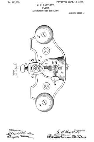
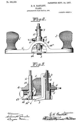
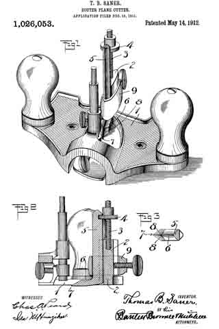
In the accompanying drawings, Figure 1 is a perspective view of a router plane with my improved cutter in place. Fig. 2 is a central vertical section. Fig. 3 is a plan view of the cutter foot, the shank being in section.

1 represents the main body of a router plane, the particular form of which is immaterial.

2 represents an upright cutter support or guide preferably provided with a screw thread 3 and an adjusting nut 4.

5 is the shank of the cutter.

6 is the foot of the cutter. The foot of the cutter projects forwardly and is pointed, as at 7. Leading back from the point 7 are two beveled inclines 8–8 on the top side of the foot, thereby forming two sharp cutting edges. The underside of the foot is, as shown in Fig. 2, pointed downwardly slightly, so that the toe end or point 7 will easily enter the wood to be cut. The guide 2 extends well down to the heel of the plane iron, as shown in sectional View Fig. 2; hence, the plane iron is given a powerful support throughout its length.

9 is a clamp, of any suitable form, for securing the cutter to the support 2. A part of the nut A projects into a notch at the back of the shank 5 of the cutter, so that as the nut is screwed up and down, the cutter will be correspondingly moved to vary the position of the point 7 of the cutter relatively to the sole of the plane.

As will be seen, in a cutter such as described, when the same is used in routing the material which is to be worked upon, an easy entrance into the material is guaranteed by the point 7. A double draw cut, which is the most effective in operation, is likewise secured by forming the point 7 substantially midway between the side edges of the foot 6. This arrangement has the further advantage of preventing any tendency toward deflecting that might otherwise exist. Again, when working across the grain, I have found by the use of this new type of cutter, all tendency to tear the wood is avoided. It is preferable that that part of the underside of the foot or toe immediately to the rear of the point 7 should be formed in a plane only slightly oblique to the sole of the plane body.

What I claim is:

In a cutter for a rabbet plane, a shank portion, a foot portion at the lower end of said shank portion and extending at an angle thereto, the toe of said foot portion being pointed, the opposite oblique sides of said foot being beveled on the top to form two oppositely arranged cutting edges, the underside of the toe immediately to the rear of the pointed cutting end being formed in a plane only slightly oblique to the sole of the plane body with which said cutter may be used whereby the two opposite side cutting edges and the pointed cutting end will lie in a substantially horizontal working plane.

THOMAS BENJAMIN SANER.

Witnesses:
EARL E. EATON,
H. W. EDWARDS.

_________________

Copies of this patent may be obtained for five cents each, by addressing the “Commissioner of Patents, Washington, D. C.”
_________________

No. 972,645 – Plane (Charles B. Rice) (1910)

[paiddownloads id=”674″]972645


UNITED STATES PATENT OFFICE.

_________________

CHARLES B. RICE, OF WASHINGTON, DISTRICT OF COLUMBIA.

PLANE.

_________________

972,645. Specification of Letters Patent. Patented Oct. 11, 1910.
Application filed April 28, 1910. Serial No. 558,164.

_________________

To all whom it may concern:

Be it known that I, CHARLES B. RICE, a cltizen of the United States, residing at Washington, in the District of Columbia, have invented a, new and useful Plane, of which the following is a specification.

This invention relates to planes of the type which are employed for grooving purposes, although the tool of the present invention is susceptible of other uses if desired.

The object of the invention is to provide a strong simple, durable and inexpensive grooving tool which can be used in a variety of positions and for a large number of useful operations and which can be easily and quickly adjusted to meet the requirements of different kinds of work, such for example as the grooving of doors and door frames for the purpose of securing the door locks and fittings in position.

With the foregoing and other objects in view which will appear as the description proceeds, the invention resides in the combination and arrangement of parts and in the details of construction hereinafter described and claimed, it being understood that changes in the precise embodiment of invention herein disclosed can be made within the scope of the claims without departing from the spirit of the invention.

In the accompanying drawing forming part of this specification:– Figure 1 is a plan view of a grooving tool constructed in accordance with the invention. Fig. 2 is a side elevation thereof. Fig. 3 is a transverse section on the line 3–3 of Fig. 1. Fig. 4 is a similar section on the line 4–4 of Fig. 1. Fig. 5 is a detail perspective view showing a modified construction of bit post. Fig. 6 is a detail perspective view of one of the improved bits. Fig. 7 is a view similar to Fig. 6 showing another form of the improved bit. Fig. 8 is a perspective view of the clamping plate.

Like reference numerals indicate corresponding parts in the different figures of the drawings.

The reference numeral 1 indicates a base plate the lower surface 2 of which, as shown in Fig. 2, comprises a bearing surface which fits against the material to be operated upon, the bit 3 being caused to project beyond the bearing surface 2 through the opening 4 formed in the base 1. The base plate 1, at the forward end thereof, is provided with an upwardly extending curved handle or grip 5.

The bit 3 preferably is of the form indicated in Fig. 6. That is to say the bit is formed with a shank or plate 6 with which is adjustably connected the shank or plate 7 of a gage member 8 which determines the distance which the cutting tool 3 shall penetrate into the surface which is being operated upon. The gage 8 preferably consists of a tongue which projects in an oposite direction to the cutting edge of the tool 3. The preferred means of adjustably connecting the shank 7 with the shank 6, consists of a, screw 9 which projects through a slot 10 formed in the plate 7, said slot having an enlargement 11 at one end thereof to permit the initial introduction of the screw 9.

The means for securing the bit or cutting tool 3 in position within the opening 4 in the base plate, preferably consists of a post or standard 14 which, as shown in Fig 3, rises from the face of the base plate 1 adjacent the rear end of the opening 4, said post 14 being extended at its lower end to form the lateral shoulders 15 and the transversely extending flange 16. The shank 7 of the bit gage, and the shank 6 of the bit are fitted flat against the post 14 on the side thereof next to the openings 4 with the cutting edge of the tool projecting through said opening. A rectangular loop member 17 is then fitted downward over the post 14 so as to surround the bit shank 6 and plate 7, said loop member 17 resting at its lower end upon the shoulders 15 as shown in Fig. 5. A plate 18 is then fitted against the rear face of the post 14 between said post and the loop member 17. The plate 18, as shown in Fig. 8, is thickened adjacent its upper end as indicated at 19 and a set screw 20 is threaded through said thickened portion 19. By tightening the set screw 20 the point thereof projects against the rear face of the post 17 and the lower portion of the plate 18 serves to draw the loop member 17 tightly around the bit shank 6 whereby to bind the same firmly in any position to which it has been adjusted on the front face of the post 14.

For the purpose of providing a second bearing surface 25 which is arranged at a right angle to the bearing surface 2 and has an bit 3 projecting therefrom, the base plate 1 is formed or provided along one side thereof with an upstanding flange 26, said flange, as shown in Fig. 2, being formed with an inclined edge 26 which causes it to be narrow at the forward end of the stock of the plane and broad at the rear end thereof. The extreme rear end of the flange 26 is provided with a curved handle 28 which is disposed at a right angle with respect to the handle 5 at the forward end of the stock. The bit 3 on the bearing face 25, as shown in Fig. 1, projects in an opposite direction to the bit 3 on the bearing plate 2 as shown in Fig. 2. When the bearing plate 5 is employed therefore the stock is manipulated in the opposite direction to that in which it is moved when the other bit is being used. The bit 3 on the bearing surface 25 projects through an opening 30 formed in the flange 26, the upper edge of said opening 30 being inclined so as to be in parallelism with the edge 27 of the flange 26. The bit 3 of the bearing face 25 is mounted in the same way as the bearing face 2. That is to say it is mounted upon a post 14 which is provided with shoulders 15 and an enlarged flange 16 connected with the flange 26, a loop member 17 being fitted around the bit 2 and the shank 7 of the gage member 8 thereof and a plate 18 having a thickened end 19 and set screw 20 as shown in Fig. 8 being employed to tighten the bit and hold it in any position to which it has been adjusted. The post 14 connected with the flange 26 of course extends at a right angle to the post 14 connected with the base plate 1. This is necessitated by the fact that the two bits 3 are arranged with their cutting edges at right angles to each other.

If desired, the plate 18 and set screw 20 illustrated in Fig. 8 may be dispensed with, and the modified construction of clamping device shown in Fig. 5 may be employed. In this clamping device all the parts except the plate 18 and screw 20 are the same as previously described. In place of the clamping plate 18 a pair of plates 35 and 36 are employed, said plates being riveted together at their lower ends as indicated at 37 and being adapted to be forced apart at their upper ends by means of a lever 38 which is pivoted at 39 on ears 40 formed on the plate 35. When the lever 38 is thrown upward into inoperative position, the upper ends of the two plates 35 and 36 spring together and thus release the pressure on the loop members 17 so that the bit can be adjusted upward or downward if desired. When the bit has been properly adjusted, the lever 38 is thrown downward so that the end thereof bears against the plate 36 and forces the upper end of said plate away from the upper end of the plate 35. The separation of the plate causes the necessary pressure to be wrought to bear on the loop member 17 to hold the bit in the position to which it has been adjusted.

The plane of the resent invention is provided with a laterally disposed gage member 40 which is adapted to cooperate with the bearing surface 2 in performing certain classes of work in which the groove to be formed is located some distance away from the edge by which the plane is to be guided. The gage member 40 consists of a plate as shown in Fig. 3, the upper and lower surfaces of which are parallel with the bearing surface 2 of the plane. The plate 40 is so disposed with relation to the bearing surface 2 that the upper surface thereof is slightly below the plane of the bearing surface 2 so that the plate 40 can if desired be adjusted inward beneath the bearing surface 2. The gage plate 40 is provided at one end with a depending flange 41 and at the other end with an upstanding flange 42. The upstanding flange 42, as shown in Fig. 1 is provided with four threaded openings 43–43 and 44–44. Connected with either the set of perforations 43–43 or 44–44 is a pair of supporting rods 45 which extend through the flange 26 of the base plate 1 and through a flange 47 formed along the opposite edge of the base plate 1 from the flange 26. The rods 45 extent loosely through the flange 47 and are adapted to be locked in any position to which they have been adjusted by means of set screws 48 which extend downward through the flange 47 and are adapted to engage the rods 45. By loosening the set screws 48 the gage member 40 can be adjusted a greater or lesser distance away from the base plate 1. As indicated in Fig. 3, the plate 40 can be adjusted toward the base plate 1 to such an extent that the depending flange 41 will lie beneath the bearing surface 2 and will thus act as a gage for the cutter when working close to the edge by which the plane is being guided. If it be desired to arrange the gage member 40 on the opposite side of the device from that shown in Fig. 1, the rods 45 are unscrewed from the flange 42 and are reversed in the flange 47. The flange 42 is then connected with the threaded ends of the rods 45, the pair of threaded openings 43–43 being employed so that the forward ends of the gage member 40 will not project beyond the forward end of the base plate 1. Moreover, the gage plate 40 can be reversed while remaining on the same side of the plane as that shown in Fig. 1. By means of this reversal the plate 40 can be caused to project outward with relation to the flange 42 instead of inward toward the base plate 1 as shown in Fig. 3. It will also be obvious that the gage member 40 can be entirely removed from the plane whenever desired by simply withdrawing the rod 45.

The modified form of bit illustrated in Fig. 7 of the drawing is the same as that shown in Fig. 6 except that the gage plate instead of being formed at the lower end thereof with a tongue 8, is provided with a pair of downwardly extending cutters or points 50, which serve to cut the edges of the groove a little deeper than the flat bit 3 is adapted to cut the same. In this manner the cutter 50 serves to produce a cleanly defined groove in the operation, for example, of grooving the end of a door to receive the door lock or fitting.

The tool of the present invention is strong, simple, durable and comparatively inexpensive in construction as well as thoroughly efficient and practical in operation.

What is claimed as new is :–

1. A plane having a plurality of bearing surfaces one having a handle at one end and the other having a handle at the other end, said handles being angularly disposed with relation to each other, and a bit on each of said bearing surfaces having its cutting edge projected in the direction of the handle of said bearing surface.

2. A plane having a pair of bearing surfaces one of said surfaces being wider at one end than the other and having a handle at the wide end thereof and the other of said surfaces having a handle at the opposite end.

3. A plane having a bearing surface formed with an opening, a post adjacent said opening, shoulders adjacent the lower end of said post, a loop member surrounding said post and resting against said shoulders, a bit having a shank arranged between said posts and said loop on one side, and an adjustable member arranged between the other side of said post and said loop member for tightening the same on said bit.

4. A plane having a bit provided on the rear face thereof with an adjustable gage.

5. A plane having a bit provided with a cutting edge projecting in one direction, and a gage plate connected with said bit and having a gage tongue projecting in the opposite direction froin the cutting edge of the bit.

6. As a new article of manufacture, a plane bit having a cutting edge and a shank, and a gage plate adjustably connected with said shank for regulating the depth of the cut of said bit.

In testimony that I claim the foregoing as my own, I have hereto afhxed my signature in the presence of two witnesses.

CHARLES B. RICE.

Witnesses:
JAMES W. CROSS,
SAMUEL M. HOWELL.

No. 865,560 – Plane (George Hunter Bartlett) (1907)

[paiddownloads id=”646″]865560


UNITED STATES PATENT OFFICE.

_________________

GEORGE HUNTER BARTLETT, OF BUFFALO, NEW YORK, ASSIGNOR TO THE STANLEY RULE &
LEVEL COMPANY, OF NEW BRITAIN, CONNECTICUT, A CORPORATION OF CONNECTICUT.

PLANE.

_________________

865,560. Specification of Letters Patent. Patented Sept. 10, 1907.
Application filed May 21, 1907. Serial No. 374,960.

_________________

To all whom it may concern:

Be it known that I, GEORGE HUNTER BARTLETT, a citizen of the United States, residing at Buffalo, Erie county, New York, have invented certain new and useful Improvements in Planes, of which the following is a full, clear, and exact description.

My invention relates to improvements in planes, and particularly to that type of a plane termed a router, a tool which is used by carpenters, cabinet-makers, stair-builders, pattern-makers and wheelwrights. The function of the same is to rout out and smooth the bottom of grooves, panels and other depressions below general surfaces of woodwork.

The object of the invention is to provide an attachment whereby the tool may be converted from the open-throat plane to the closed-throat plane, the attachment being so mounted that it may be adjusted to a nicety. Beyond this the attachment is also so mounted that any adjustment of the bit or cutter will not disturb the same.

In the accompanying drawings Figure 1 is a plan view; Fig. $2 is a front elevation; and Fig. 3 is a vertical section taken through the middle of the plane.

1 is the main body or stock. 2–2 are the handles at opposite ends thereof. The stock or body 1 is cut partially through on its lower side to form the throat, in which the bit or cutter 3 stands, projecting forwardly therein, as best seen in Figs. 1 and 3.

4 is an arched bridge overstanding the forward end of the throat and uniting the two sides of the stock as best seen in Figs. 1 and 2.

5 is a stationary bearing post for the shank of the cutter or bit. Ordinarily the shank of a cutter is square in cross section and the forward side of the post 5 should, therefore, be shaped approximately thereto to furnish a superior support. The rear side of the post may also be flattened or grooved to receive the forward end of a lock-screw 6 carried by a collar 7, which extends around the post 5 and engages the shank of the cutter 3, as best seen in Fig. 1.

8 is a screw-threaded extension on the post 5, upon which extension is mounted a correspondingly screw-threaded adjusting nut 9, the edge of which makes a connection with the shank of the cutter so that by loosening up on screw 6 and adjusting the nut 9 up and down, the cutter can be raised and lowered to project to the desired depth below the sole of the body.

10 is a bracket preferably formed integrally with the arch or bridge 4.

11 is a set-screw for the bracket 10.

12 is a vertically adjustable post mounted in the bracket 10 and carrying at its lower end what I term a throat-closer or adjuster 14, which latter may, if desired, be detachably secured to the post 12 by means of a collar 14a and binding-screw 15.

The bracket 10 is preferably formed at the rear of the bridge or arch 4.

For certain kinds of work it is preferable to have a closed throat while for other kinds of work it is preferable to have an open throat. With my improvement the plane may be converted into one or the other at will. The adjustment up and down for the cutter in no way affects or disturbs the correct position of the member 14 after the latter has once been adjusted. By separating these parts and making them entirely independent, to wit, the adjustment for the cutter and the adjustment for the member 14, much unnecessary labor is avoided and a superior structure afforded.

The form of the bracket 10 may, of course be modified in many ways, similar clamping means to those shown to the rear for the cutter, being permissible.

What I claim is —

1. A router plane comprising a frame or body, a throat entering the same at one side thereof, a bridge for the open end of said throat, a cutter and means for holding the same at the rear of the throat, a throat adjuster and a bracket on said bridge for holding the adjuster in said throat forward of the cutter.

2. A router plane comprising a body or frame, a throat extending into the same at one side, an arched bridge connecting the opposite sides of the body near the forward end of the throat, a cutter, means for adjustably supporting said cutter at the rear of said throat, a throat-adjuster, a bracket on said bridge for supporting said adjuster.

GEORGE HUNTER BARTLETT.

Witnesses:
NORMAN O. DE BOCK,
FRANK C. FERGUSON.

No. 793,297 – Router (Frederick Hesley) (1905)

[paiddownloads id=”622″]793297


UNITED STATES PATENT OFFICE.

_________________

FREDERICK HESLEY, OF WATERTOWN, NEW YORK.

ROUTER.

_________________

SPECIFICATION forming part of Letters Patent No. 793,297, dated June 27, 1905.
Application filed March 1, 1905. Serial No. 247,881.

_________________

To all whom it may concern:

Be it known that I, FREDERICK HESLEY, a citizen of the United States, residing at Watertown, in the county of Jefferson and State of New York, have invented certain new and useful irnprovernents in Routers, of which the following is a specification.

This invention relates to improvements in routers designed for use by carpenters and pattern and cabinet makers for cutting channels or grooves in woodwork, &c.

The object of the invention is to provide a router which is simple in construction, strong, and composed of but a few parts and in which provision is made for interchangeably applying cutting-tools of different size and shape and in which the cutting-tool is provided with “dadoes” or cutting-spurs for the purpose of rendering the work ot channeling and grooving more effective and rapid.

The invention further consists of novel and simple means for adjusting the cutting parts.

The invention further consists in a router comprising the construction and arrangement of of parts hereinafter set forth in the drawings and detailed specification and particularly pointed out in the claims.

In the accompanying drawings, Figure 1 is a plan view of the router. Fig. 2 is a front elevation of the same. Fig. 3 is a vertical section on the line a a of Fig. 1. Fig. 4 is a horizontal section ot the tool holding and adjusting parts, substantially on the line x x of Fig. 23. Fig. 5 is an elevation ot the hollow tool-post, showing the semicircular guide or key in operative position and its relation to the other parts.

Similar reference-numerals are given to corresponding parts throughout the several figures of the drawings.

The base or body portion 2 is preferably made of cast-iron in a single piece and in the term as shown in the several figures ot the drawings.

3 represents the under surface or sole of the body 2, and it is intended to be finished with a smooth and level surface.

4 represents the handles, cast with the base 2 and disposed at each end on the upper side of the base, as shown in Figs. 1 and 2; but I do not wish to limit myself to this style of handles, and I may prefer to employ wooden handles, such as are commonly used on devices of this class.

4′ represents the hollow portion ot the handles, formed in the casting by means of a core in the manner usually employed in such work.

5 represents a hollow tool-post or sleeve projected upwardly from the central portion of the body 2. This sleeve or post is cast with the body and is bored out to receive and support the tool shank or stock 6. The shank 6 is threaded almost its full length, and therefore is capable of a wide range of adjustment. It is held from revolving in sleeve 5 by means of the keyway 7, which is cut lengthwise of said shank. The feather or key 8 is rigidly secured to the inner side of sleeve 5 in position to engage the keyway 7, and thereby guide the tool-shank 6 when being adjusted and also to prevent the cutting-tool from having any lateral play.

9 represents an elongated adjusting nut or gland the lower portion of which is bored out to operatively fit over the tool-post 5, upon which it is intended to turn freely, the upper end 9′ being internally threaded to engage and operate the threaded tool-shank 6, by means of which the latter is adjusted or set. The adjusting-nut 9 is roughened or knurled at 10 for the purpose of aiding in operating the same by hand.

11 represents an annular groove or keyway formed around the outer surface ot the hollow tool-post 5, in which the sernicircular guide or key 12 is slidably disposed.

13 represents a set-screw which passes through a threaded hole in the adjusting-nut 9. The point of said screw engages and drives the guide or key 12 by means ot the hole or socket 14, which is formed in said guide.

The purpose of the parts 11, 12, 13, and 14 is to afford simple and effective means in the nature of a swivel for operatively holding in place the adjusting-nut and at the same time allowing said nut to revolve freely upon the sleeve or hollow tool-post 5, thereby accomplishing the adjustment of the shank and cutter in a direct and simple manner.

15 represents the cutting tool or bit, being provided with a tine or shank 16, which is adapted to fit tightly in the socket 17, formed in the lower end of the tool stock or shank 6. By this means cutters or bits of any desired shape or size may be interchangeably used in connection with the common tool-shank and may be provided at much less expense than if the stock and cutting-tool were made in one piece. A set-screw 18 is provided to secure and hold the cutter or bit in place.

19 represents the dadoes or cutting-spurs, formed upon the under side or edges of the bit or cutter, as shown in Figs. 2 and 3, the object of these spurs being to enable the operator to cut a groove or channel in either direction across a piece of wood and leave the edges and corners of the groove in a smooth and neat condition. Without these spurs it is practically impossible for the workmen to guide the router so as to form straight and evenly-cut grooves, especially when the grooves are to be cut across or against the grain of the wood, because in such cases the cutting knives or bits will invariably splinter and mar the work. These spurs or dadoes may partake of any suitable form or shape. They are preferably formed with the cutting-tool by means of drop-forging and may be disposed at any convenient point on the lower edges or corners of the bit.

The open space 20, provided in the central portion of the base 2 in front of the cutter 15, is for the purpose of preventing the shavings or chips from clogging or obstructing the cutter. The arched portion 21 is intended to form a bridge or tie across the open space 20 for the purpose of strengthening that part of the base and to prevent the choking of the device by the accumulation of shavings and also to render the router more serviceable in channeling and grooving the inner surface of a small circle.

22 represents slotted openings in the body portion 2 on either side of the cutting part, which are used in applying adjusting-gages 23, which are used for guiding the device, the object of these gages being to enable the operator to adjust the router so that a groove may be cut exactly parallel with a certain part of the work and also to limit the lateral depth or distance at which the groove or channel is to be formed. The gages 23 extend below the base 2, as shown in Fig. 2.

24 represents a portion of the gage which extends above the base or body and which is threaded to receive a thumb-nut 25, employed for tightening and holding the gage when set.

It will be obvious to any one skilled in the art that various modifications and changes may be made in carrying my invention into effect, and I therefore do not wish to limit myself to the precise construction and arrangement of the parts as herein shown and described.

Having thus described my invention, what I claim as new, and desire to secure by Letters Patent, is —

1. A router of the class described, comprising a base having a hollow tool-post integrally formed thereon, an annular groove formed on said tool-post, a semicircular guide or key slidably fitting said groove, an adjusting nut or gland operatively mounted upon said hollow tool-post, a set-screw connecting said adjusting nut or gland with said guide or key, a threaded tool-shank adjustably fitting said hollow tool-post and engaging said adjusting-nut, a keyway formed longitudinally of said tool-shank, a key rigid on said tool-post adapted to engage said keyway and to guide said tool-shank, a cutter or bit detachably connected to said tool-shank, “dadoes” or cutting-spurs formed on the under edges of said cutter or bit rearwardly of the cutting edge thereof, and a pair of handles cast upon said base, substantially as described.

2. A router of the class described, comprising a metallic base and a pair of handles cast therewith, a centrally-disposed tool-post or sleeve integrally formed on said base, a screw-threaded tool shank or stock, operatively mounted on said tool-post or sleeve, an adjusting-nut engaging said tool shank or stock and adapted to raise or lower the same, a semicircular guide or key disposed between said adjusting-nut and said tool-post or sleeve and operatively conneeted with said adjusting-nut, a cutting knife or bit joined by means of atine and socket to said tool shank or stock, “dadoes” or cutting-spurs formed on said knife or bit, and a gage to guide or limit the operation of said router, substantially as described.

3. A router of the class described, comprising a base or body, a cutting-tool having “dadoes” or spurs on the under side thereof, a tool-shank carrying said cutting-tool, a hollow tool-post formed on said base or body, a spline for said tool-shank, an adjusting-nut swiveled to said tool-post and adapted to engage said tool-shank for the purpose of adjusting the same vertically, a gage adapted to guide and limit the operation of said cutting-tool, and a handle upon said base or body, substantially as described.

4. In a router of the class described, comprising a suitable base, having a plurality of slots or openings therethrough, of a hollow tool-post or sleeve integrally formed thereon, a threaded tool shank or stock vertically movable in said sleeve or tool-post, an adjusting-nut swiveled to said tool-post or sleeve, and having its upper end internally threaded to engage and operate said tool shank or stock, a cutting tool or bit detachably connected to said tool shank or stock, cutting-spurs or “dadoes” disposed on the under edges of said cutting tool or bit, and a pair of adjustable gages movable in said slots or openings, substantially as described.

5. ln a router of the class described, the combination with the base or body having a pair of handles integrally cast or formed thereon, of a sleeve or tubular post integrally formed upon said base or body, a tool-shank slidably fitting said sleeve or tubular post, a spline-guide for said tool-shank, an adjusting-nut operatively mounted upon said sleeve or tubular post and adapted to engage and adjust said tool-shank, a semicircular guide or key between said adjusting-nut and said sleeve or tubular post, adapted to provide a swivel connection for said parts, a cutter or bit removably attached to said tool-shank, and a plurality of “dadoes” or cutting-spurs on the lower edges of said cutter or bit, substantially as described.

6. In a router of the class described, comprising a metallic base having an arch or bridge on one side thereof, of a hollow tool-post upon said base, a tool shank or stock provided with a detachable cutter, a keyway in said tool-shank and a key in said hollow tool-post adapted to guide said tool shank or stock, an adjusting-nut swiveled to said hollow tool-post by means of a semicircular guide or key, and adapted for adjusting said tool-shank and said cutter, “dadoes” or cutting-spurs on said cutter, and a pair of gages adjustably mounted in slotted openings in said base, substantially as described.

In testimony whereof I affix my signature in presence of two witnesses.

FREDERICK HESLEY.

Witnesses:
EDGAR D. BLOODOUGH,
HARRY DE WALLACE.

No. 707,085 – Recessing Or Grooving Plane (Fred Clayton) (1902)

[paiddownloads id=”567″]707085


UNITED STATES PATENT OFFICE.

_________________

FRED CLAYTON, OF PUDSEY, ENGLAND.

RECESSING OR GROOVING PLANE.

_________________

SPECIFICATION forming part of Letters Patent No. 707,085, dated August 19, 1902.
Application filed April 1, 1902. Serial No. 100,915. (No model.)

_________________

To all whom it may concern:

Be it known that I, FRED CLAYTON, a subject of the King of Great Britain and Ireland, residing at Pudsey, near Leeds, in the county of York, England, have invented a new and useful Recessing or Grooving Plane, of which the following is a specification.

My invention relates to an improved recessing or grooving plane in which various tools are interchangeable in various positions in the plane according to the nature and situation of the work required to be done, such plane being applicable for planing the bottom and sides of grooves in woodwork — such, for instance, as grooves in hoist-slides, grooves in collapsible boxes, shelf-grooves in cupboard sides, step-grooves in staircase sides, grooves in the sides of core-boxes for the ends to fit into, and grooves in patterns in to which lifting-irons, fillets, or ribs are recessed. It is applicable also for planing out the bottom of panels and all other depressions or recesses below the general surface of the wood-work.

My invention is illustrated in the accompanying drawings, in which —

Figure 1 is a plan, Fig. 2 an end view, and Fig. 3 a side view, of my improved plane, showing a right-hand side tool in position for use. Fig. 4 is a plan of regulating or adjusting slide for right-hand side tool. Fig. 5 is a plan and Fig. 6 a side view of regulating or adjusting slide for left-hand side tool. Fig. 7 is a plan and Fig. 8 a side view of bottom tool. Fig. 9 is a plan and Fig. 10 an end view of loose collar and screw by which the various tools are secured in position. Fig. 11 is an end view, and Fig. 12 a side view, of right-hand side tool. Fig. 13 is a side view, and Fig. 14 an end view, of left-hand side tool.

Similar letters refer to similar parts throughout the several views.

My improved plane consists of a frame or body B, preferably having two handles C C and fitted with five vertical tool-posts A’ A2 A3 A4 A5 in suitable positions on the said frame or body B. A right-hand side tool D, Figs. 1, 11, and 12, a left-hand side tool E, Figs. 13 and 14, and a bottom tool F, Figs. 7 and 8, are provided, the side tools D and E being fitted in the posts A’ and A2, respectively, and the bottom tool F being interchangeable in the tool-posts A3 A4 A5. The tools are held in position in the desired post so as to be adjustable vertically therein by means of a loose collar G, having thumb-screw H.

A right-hand slide K for use with the side tool D may be fitted beneath the frame or body B of the plane, this slide being secured and adjusted by means of pin M and screw N, working within a pair of parallel oblique slots P P in the frame or body B. The cutting-tool D when in position passes through a side opening R in the said slide K, the amount of cut being regulated by tapping the slide at the ends. A similar left-hand slide L is provided for use with the side tool E, this slide having side opening R’ and being similarly secured by pin M’ and screw N’, working within a second pair of parallel oblique slots P’ P’. These slides K L are removed when not required by slackening the irrespective screws N N’ and, withdrawing the pins M M’ and screws N N ’ from their respective slots, a suitable opening S in the frame being provided to allow for the insertion and withdrawal of the screw-heads. By this means the plane can he adapted to a large variety of work, the required tool being fixed in the post best suited to the purpose. Thus for planing the sides of grooves or recesses the tools D and E would be employed, fixed in the post A’, as shown in Figs. 1, 2, and 3, and in the post A2, respectively. For general purposes of planing out the bottom of grooves the tool F would be fixed on the inside of the post A3. For work in which the tool is required to go in advance of the plane the tool would be fixed on the outside of the post A3. Where the work operated upon is short and the recess deep the tool would be fixed in the post A4, so as to obtain bearing-surface both in front of and behind the tool. For work in which the tool is required to follow the plane — as, for instance, in half-lapping-the tool would be fixed in the post A5.

T represents holes for screws for attaching a curved piece of wood to the bottom of the plane-body when desired.

What I claim is —

1. The combination, with a plane-body provided with a series of separate tool-posts arranged in different planes, of a clamp for securing tools to the said posts, substantially as set forth.

2. The combination, with a plane-body provided with separate tool-posts arranged in different planes and having also oblique slots, of an adjustable slide provided with fastening devices which engage with the said slots, and a clamp for securing tools to the said posts, substantially as set forth.

3. The combination, with a plane-body provided with separate tool-posts arranged in different planes and having also two pairs of oblique slots for right and left hand side tools provided with fastening devices which engage with the said slots, and a clamp for securing the tools to the said posts, substantially as set forth.

In testimony whereof I have signed my name to this specification in the presence of two subscribing witnesses.

FRED CLAYTON.

Witnesses:
ALLAN BENNETT,
LEWIS DEXTER.

No. 685,411 – Carpenter’s Router (Albert F. Schade) (1901)

[paiddownloads id=”558″]685411


UNITED STATES PATENT OFFICE.

_________________

ALBERT F. SCHADE, OF NEW BRITAIN, CONNECTICUT, ASSIGNOR TO
STANLEY RULE AND LEVEL COMPANY, OF NEW BRITAIN, CONNECTICUT.

CARPENTER’S ROUTER.

_________________

SPECIFICATION forming part of Letters Patent No. 685,411, dated October 29, 1901.
Application filed March 6, 1901. Serial No. 50,130. (No model.)

_________________

To all whom it may concern:

Be it known that I, ALBERT F. SCHADE, a citizen of the United States, residing in New Britain, in the county of Hartford and State of Connecticut, have invented certain new and useful Improvements in Carpenters’ Routers, of which the following is a specification.

My invention relates to improvements in carpenters’ routers; and the object of my improvement is to provide simple and efficient means for adjusting the cutter.

In the accompanying drawings, Figure 1 is a plan view of my router; and Fig. 2 is a sectional side elevation, the bed plate or frame being in vertical section on the line x x of Fig. 1.

The bed plate or frame A, tool-post 3, yoke 4, and set-screw 5 are of an ordinary and well-known construction. The cutter 6 is also of an old form, excepting as I provide a recess or notch 7 in its rear side near its upper end. In the center of the tool-post 3 and projecting upwardly therefrom is the adjusting-screw 8, rigidly and permanently affixed thereto or formed thereon, so as to constitute an immovable part thereof. Upon this screw is the adjusting-nut 9, preferably having a roughened or knurled edge for convenience of manipulation. This nut is of a diameter so large as to project into the path of the upper end of the cutter 6, whereby the adjusting-nut 9 and the cutter 6 may be assembled with the edge of the nut projecting into the recess or notch 7 in the cutter 6, as best shown in Fig. 2.

It will be readily seen that the cutter may be adjusted either up or down by turning the adjusting-nut 9; also, that the parts may be assembled when desired with the adjusting-nut above the notch in the cutter or wholly removed, so that the cutter may be used without any adjusting mechanism. The cutter 6 may also be placed in the reverse position on the back side of the post, as indicated by broken lines in Fig. 2, and the same adjusting mechanism is adapted for use with the cutter in this reversed position. The construction is simple and inexpensive, and the improved device is very convenient for effecting a fine adjustment, while it in no way interferes with any of the ordinary uses of the router.

I claim as my invention —

The combination of the bed-plate, the double-faced tool-post, projecting upwardly above the said bed, the cutter fitted to slide vertically cn the sides of the said tool-post, means for confining the said cutter in place on the said tool-post, the adjusting-screw 8, centrally mounted in the upper end of the said tool-post and projecting upwardly therefrom, and the adjusting-nut 9, mounted on the said adjusting-screw and operatively connected with the upper end of the said cutter, whereby the said adjusting mechanism may be used when the cutter is placed on either side of the said tool-post, substantially as described.

ALBERT F. SCHADE.

Witnesses:
H. S. WALTER,
E. G. HOFFMAN.

No. 609,681 – Router (Allen J. Kniffen) (1898)

[paiddownloads id=”537″]609681


UNITED STATES PATENT OFFICE.

_________________

ALLEN J. KNIFFEN, OF SCHENECTADY, NEW YORK.

ROUTER.

_________________

SPECIFICATION forming part of Letters Patent No. 609,681, dated August 23, 1898.
Application filed September 27, 1897. Serial No. 653,151. (No model.)

_________________

To all whom it may concern:

Be it known that I, ALLEN J. KNIFFEN, a citizen of the United States, residing at Schenectady, county of Schenectady, State of New York, have invented certain new and useful Improvements in Routers, of which the following is a specification.

This invention relates to that class of wood-working-tools known as “router-planes,” or, as more commonly called, “routers.”

The object of the invention is to provide a router in which the cutting-tool can be adjusted with precision and accuracy and secured in its adjusted position and also can be readily and quickly mounted in its support and removed therefrom.

The invention consists in a router constructed and arranged as hereinafter set forth and claimed.

Referring to the accompanying drawings, Figure 1 is a perspective view of a router constructed in accordance with this invention. Fig. 2 is a vertical section thereof through the middle,with the cutting-tool in full view; and Fig. 3 is a detail view, in horizontal section, showing the means for holding and securing the tool in place.

The router is provided with a base 1, as here shown of an oblong rectangular shape, having the two side recessed portions 2 and the central rectangular opening 3. Suitable handles 4 are mounted in the recessed portions 2. The back of the rectangular opening is formed with the raised portion 5, on which is mounted the cutting-tool. This consists of the cutting portion 6 on the lower end of the shank 7. The shank 7 is removably located in sleeves 8 9 8 of three bracket-arms 8′ 9′ 8′, the sleeves 8 8 being fixed to the upper and lower ends of a plate 10, mounted in the raised portion 5 in any suitable manner — as, for example, by means of a dovetailed joint — and secured thereto by a screw or other suitable means. The sleeve 9 is vertically movable between the sleeves 8 8, preferably in a suitable groove in plate 10, as here shown, especially in Fig. 3 of the drawings, the rear portion of sleeve 9 engaging a groove 10′, which serves as a guideway for the sleeve 9, as well as a seat therefor when it is locked in position. The sleeve 9 has also a slight lateral play. The sleeve 9 is provided on its rear with a threaded arm extending through a vertical slot 12 in plate 10 and the slot 13 in the raised portion 5, the slot 13 being in alinement with the slot 12. A wing 14 and washer 15, lying across the slot 13, are mounted on the arm 11 and serve to lock the sleeve 9 after the adjustment of the tool is effected and by drawing it laterally to clamp the tool- shank. The sleeve 9 is moved by means of an adjusting-screw 16, which has a threaded engagement with the bracket-arm 9′, the upper and lower ends of said adjusting-screw 16 being plain or unthreaded and extending through holes in the bracket-arm 8’. The screw 16 is held in place by a washer 17, located thereon beneath the upper bracket-arm 8’, and is operated by means of a milled head 16′ at its upper end. The shaft 7 of the cutting-tool extends through and is adapted to be slid vertically in the sleeves 8 9 8. In order that the shaft 7 may not drop out of the sleeve 8 9 8 when the wing-nut 14 is loosened, some means is necessary to hold it in frictional engagement therein, which also permits of its being adjusted in said sleeve before the sleeve 9 is adjusted. Any suitable means may be employed for holding the shaft in such frictional engagement.

As here shown, more particularly in Fig. 3, a spring 13 is employed, mounted in a recess 19 in the back of sleeve 9 and bracket-arm 9’, the outer or free end of spring 18 projecting into sleeve 9 and bearing against the shank 7. The rear of shank 7 is preferably formed with the flattened portion 20 to afford room and a better surface for the spring 18 to bear against shank 7.

In this class of devices it is necessary to readily and precisely adjust the cutting portion 6 to the depth required below the base 1, and this is effected as follows: The wing-nut 14 being loosened, the shank 7 is held in the sleeves 8 9 8 by frictional engagement of spring 20 and maybe pushed to approximately the desired position. The precise adjustment of the cutting-tool is then effected by turning the thumb-nut 16′, which moves the sleeve 9, carrying the cutting-tool, to the exact position desired. The tool is then rigidly held in such position by tightening the wing-nut 14, which draws the sleeve 9 against the groove 16’, firmly clamping the tool-shank and locking the parts in position. This binding action is very essential in tools of this kind, because if there is the slightest vibration in the tool it will not perform the work properly and will, as it is called, “chatter.” By having the parts mounted on the plate 10, as shown, they may be readily and quickly disconnected from the raised portion 5 for packing or repair by unfastening the plate 10 and sliding it out of position.

If preferred, in lieu of the plate 10 the bracket-arms 8′ may be mounted directly on the raised portion 5.

It will thus be seen that by means of a router constructed and arranged as herein set forth the cutting-tool can be easily placed in position or removed, will be held in this movable and removable position by frictional engagement, and can be quickly and precisely adjusted to the desired cutting position and locked in place.

Having described my invention, what I claim as new, and desire to secure by Letters Patent, is —

1. A router having fixed sleeves mounted on bracket-arms, an intermediate sleeve movable vertically and slightly laterally mounted on a movable bracket-arm, and an adjusting-screw for vertically adjusting the movable sleeve, in combination with a cutting-tool having a shank held in frictional engagement in said sleeve, and means connected with the movable sleeve for locking it to the main frame of the tool which also draws the movable sleeve laterally to clamp the tool-shank, as set forth.

2. A router having fixed bracket-arms carrying the sleeves, a vertically-movable bracket-arm carrying a sleeve which may be moved slightly laterally, and an adjusting-screw for vertically moving the movable sleeve, a groove in the main portion of the tool with which the movable sleeve engages, and a threaded arm, projecting from the movable sleeve, and having a nut for binding and locking the movable sleeve to the main frame of the tool and also drawing it laterally, in combination with a cutting-tool having its shank held in frictional engagement with said sleeve, as set forth.

3. A router having fixed brackets carrying sleeves, a vertical groove between said brackets, a movable bracket and sleeve engaging and movable vertically and slightly laterally in said groove, an adjusting-screw engaging said bracket, a threaded arm projecting from said movable sleeve through a slot in the bottom of said vertical groove, and a nut on said threaded arm for locking said movable sleeve in said groove, in combination with a cutting-tool, having its shank held in frictional sliding engagement in said sleeves, as set forth.

In witness whereof I have hereunto set my hand this 18th day of September, 1897.

ALLEN J. KNIFFEN.

Witnesses:
Mrs. A. J. KNIFFEN,
B. B. HULL.

No. 420,232 – Plane For Planing The Bottom Of Grooves In Moldings And Ornamental Wood-Work (Gustav Heÿmeier) (1890)

[paiddownloads id=”458″]420232


UNITED STATES PATENT OFFICE.

_________________

GUSTAV HEŸMEIER, OF BREMEN, GERMANY.

PLANE FOR PLANING THE BOTTOMS OF GROOVES
IN MOLDINGS AND ORNAMENTAL WOOD-WORK.

_________________

SPECIFICATION forming part of Letters Patent No. 420,232, dated January 28, 1890.
Application filed June 1, 1889. Serial No. 312,910. (No model.)

_________________

To all whom it may concern:

Be it known that I, GUSTAV HEŸMEIER, sculptor, of Bremen, in the Free State of Bremen and German Empire, have invented a new and useful Improvement in Planes for Planing the Bottoms of Grooves in Moldings and Ornamental Wood-Work, of which the following is a specification, reference being had therein to the accompanying drawings.

My invention relates to tools for planing the bottoms of grooves in moldings and ornamental wood-work, and has for its object to provide an effective tool for that purpose.

The invention consists in a plane of the character specified, constructed as hereinafter described and claimed.

Reference is to be had to the accompanying drawings, forming a part of this speciiication, in which similar letters of reference indicate corresponding parts in all the figures.

Figure 1 is a front view of the invention. Fig. 2 is a bottom view. Fig. 3 is a cross-section on the line A B of Fig. 1. Fig. 4 is a view of the blade with its guard-plate, and Fig. 5 is a cross-section of one of the handles of the tool on the line C D of Figs. 1 and 2.

The invention consists of a frame a, preferably hollow, as shown, and made of metal, and constituting the central portion a’ and the handles a2. On the bottom of the frame a is centrally located a plate b, secured by screws b’ to the central portion a’ of frame a. The plate b is provided with an opening b2, through which projects a blade c extending up through an opening b3 in the top of frame a, the blade c being movable through the openings b2 and b3. The blade c is clamped in fixed position by means of a shield-plate f also projecting through openings b2 and b3, and a screw g, passing through a washer g’, a slot g2 in frame a, over which the washer g’ extends, and a slot c’ in blade c, and engages plate f. By means of this construction the plate f and blade c may be adjustably raised and lowered and clamped in position. Within the central portion a’ is also located a vertical guide-piece e, projecting through an opening e’ in the plate b and opening e2 in the top of frame a, and vertically adjustable by means of a screw d engaging the guide-piece e and extending through a slot d’ in frame a, and a washer d2 overlapping the slot d’. The lower end of piece e projects in front of the projecting end of blade c, is in the form of a tooth, and is made of bone or other suitable material.

The piece e prevents the blade c from cutting too deeply into the wood.

The depth of the cavity to be planed is determined by the length of the blade c projected beyond the plate b.

The lower end of the plate f is formed with the rounded edge f’, and when the bottom of a groove is to be planed the plate f is adjustably lowered so as to bring its lower end down to the cutting-edge of the blade c, and the shape of the curved bottom of the groove is thereby retained while the tool is planing the bottom of the groove.

Having thus fully described my invention, l claim as new and desire to secure by Letters Patent —

A tool for planing moldings, consisting of the frame a, with handles a2, the removable plate b, with openings b2 e’, the vertically-adjustable curved shield-plate f, and the vertically-adjustable slotted blade c, projecting through opening b2, the binding-screw g, extending through slotted blade c and engaging plate f and the vertically-adjustable tooth e, projecting in front of the edge of blade c, and having the adjusting-screw d extending through the slot d’ in frame a, and the overlapping washer d2, substantially as shown and described.

In witness whereof I have hereunto set my hand in presence of two witnesses.

GUSTAV HEŸMEIER.

Witnesses :
EARNST BIERNRITH,
HUGO MÜHLENBACH.

No. 356,429 – Routing-Tool (Henry F. Stearns) (1887)

[paiddownloads id=”419″]356429


UNITED STATES PATENT OFFICE.

_________________

HENRY F. STEARNS, OF SARATOGA SPRINGS, NEW YORK, ASSIGNOR OF
ONE-HALF TO EDMOND G. RAWSON, OF SAME PLACE.

ROUTING-TOOL.

_________________

SPECIFICATION forming part of Letters Patent No. 356,429, dated January 18, 1887.
Application filed June 22, 1885. Serial No. 169,356. (No model.)

_________________

To all whom it may concern:

Be it known that I, HENRY F. STEARNS, a citizen of the United States, residing at Saratoga Springs, in the county of Saratoga and State of New York, have invented certain new and useful Improvements in Routing-Tools for Workers of Wood, of which the following is a specification.

My invention relates to improvements in routing-tools in which the stock is provided with a mouth having on one of its sides a way for holding the cutting-tool and a wedging-piece and an adjustable gage working in the arms of the tool, all of which I will hereinafter particularly describe and set forth; and the objects of my invention are to provide in a routing-tool adjustable and interchangeable cutting-tools, which will be securely held from shifting in the mouth of the tool and have the gaging devices adapted to be variously adjusted and set at either right or left hand side of the cutting-tool and at any desired distance therefrom as the work to be done may require. I attain these objects by the mechanism illustrated in the accompanying drawings, in which —

Figure 1 is a view of the tool from above. Fig. 2 is a longitudinal sectional elevation. Fig. 3 is a cross-section taken at line 1 in Fig. 1. Fig. 4 is a view of the mouth of the stock with the cutting-tool and wedge removed, and showing the tool-guiding way. Fig. 5 is a plan view of a cutting-tool and an end view of the same, showing the coacting way made therein.

The same letters of reference refer to like parts throughout the several views.

The stock A, arms A’, and handles A2 A2 of this tool may be made in one piece of malleable iron, or be made of wood and iron combined, if preferred. The stock A is made with a gradually-contracting mouth, B. Across the upper portion of this mouth, and arranged slightly to one side of the center of its width and running longitudinally in direction of arms A’, is bar b, preferably made solid with the end walls of said mouth, or securely fixed therewith. Made with the rear side wall, a, of this mouth is the way c, which is shown in Figs. 3 and 4 to project a short distance past the plane of said rear wall.

C is the cutting-tool, made with any form of cutting bit or edge usually employed for grooving, channeling, beading, or forming moldings, or for incising. Made central in the width of this cutting-tool and in its rear side from its upper end, or near the cutting bit or edge, is the way c’, corresponding in size and form with way c, made with the rear wall, a, of mouth B, so that the former will receive the latter and permit the shank of the tool to have a full bearing on the surface of wall a of the mouth of the tool. These ways may be made to be reversed in their respective forms by making that in wall a of mouth B in the form of a groove instead of a projection, as shown, and that in tool C in the form of a projection instead of a groove, as shown. These ways c c’ in the respective pieces co-operate together to hold the cutting tool or blade C from shifting or being moved out from its normal set position in the mouth of the stock, and allow a variety of tools or blades, C, of differing widths to be employed within mouth B without the least liability of shifting when the tool is being operated.

D is the wedge, having a shallow groove, d, running across its front side, as shown in Fig. 3, for engagement with holding-bar b. The lower end of this wedge is made with an incline, as shown in the same figure, so as to permit an opening between the tool or blade below and the front wall of mouth B, for passage of the shavings from the cutting bit or edge of the blade C. In the upper end portion of this wedge D is made a screw-threaded hole, into which works the set-screw f by which, through wedge D, the cutting tool or blade C is securely held in its adjusted position and length of projection below the sole or face m, of the stock, which face is curved in its surface. Made in arms A’ A’ are slots E E, extended to any preferred distance from stock A toward handles A2.

F is an adjustable gage-lip provided with a projection, g, which nicely fits in slots E, for holding with the same to prevent the gage-lip from shifting sidewise. This projection is made with tail-piece F’ of the gage-lip, and has projecting upward from it the screw-threaded stem h. Nicely fitting this stem h is the screw-threaded finger-nut H, for securing this gage-lip at any point distant from the cutting tool or blade C. This gage-lip and its holding device are adapted to be used in the slot E of either of the arms A’, as may be required for right or left hand work.

By my above described improvements I obviate the use of several different bodies of routing-tools as heretofore required by carriage-makers, cabinet-makers, and other workers of wood for different operations or kinds of work, and with a variety of cutting blades or tools, C, provided each with a suitable form of cutting edge or bit, a workman can form in the wood on straight or curved lines, and on the right or left hand edges of the pieces, grooves, channels, beads, moldings, flutings, or other raised or sunken surfaces, as may be required.

The mouth of the router, being arranged to be vertically over the cutting-bit of tool C, will deliver the shavings upward from the same in a free manner instead of in a forward direction, as is usual in routers heretofore made, and the shavings will be freely delivered from the cutting-bit and without the least liability of choking the tool, as heretofore. The coacting ways c c’, made with the rear side wall of the mouth of the stock and the rear side of the shank of the cutting-tool C, operate to hold that tool firmly from shifting in any direction, and the bar b, operating with the groove d of wedge D, holds the latter from moving in either direction end wise, While the wedge D, with the set-screw f operates to hold the tool or blade C secure to its place, with its cutting-edge projecting below the sole of the stock to the point adjusted to without the least liability of its being raised, and also allows this cuttlng-blade to be readily set to cut deeper from time to time, as may be required in the progress of the work.

The spokeshave-blade can readily be applied and be firmly held and shifted in either direction in relation to the month of the stock A. The stock, with its slotted arms and handles, operating to serve as the body of a spoke-shave, being well adapted to receive the above-described shaving-blade S, obviates the use and expense of a special and individual stock, as heretofore required.

The stock A and its mouth B may be made of any suitable length, so as to receive two or more cutting-tools, C, for grooving or incising or beading two or more surfaces at a time, as may be preferred. The curved surface of face m of the stock running from one side to the other enables the operator, by slightly turning the stock, to cut with a greater or less depth into the wood, and thereby obviates the necessity of setting the cutting-blade C (for making different depths of cuts) several times before finishing the work being done.

If preferred, a small bracket, z, made with the rear side of the stock, and provided witli a set-screw, x, working in its head end, and its lower end working in a small sleeve attached to the upper end of the tool C and held by a key, may be employed ibr raising or lowering the tool, as is the practice with irons in planes.

Having described my invention, what I claim, and desire to secure by Letters Patent, is —

In a routing-tool, the combination, with a stock provided with similarly-slotted arms, which are extended in opposite directions from the tool mouth, of an adjustable gage-lip, which is provided with a screw-threaded stem and nut and constructed to be used interchangeably in said slotted arms, a cutting-blade which is provided on its rear side with the way c’, which engages with way c, made with the rear side wall of tool-mouth B, and the mechanism described for adjusting and securing said cutting blade in said tool-mouth, substantially as and for the operations and purposes set forth.

HENRY F. STEARNS.

Witnesses:
A. N. SHEPHERD,
W. A. PIERSEN.

No. 350,352 – Router-Plane (John L. De Huff) (1886)

[paiddownloads id=”414″]350352


UNITED STATES PATENT OFFICE.

_________________

JOHN L. DE HUFF, OF READING, MASSACHUSETTS.

ROUTER-PLANE.

_________________

SPECIFICATION forming part of Letters Patent No. 350,352, dated October 5, 1886.
Application filed February 20, 1886. Serial No. 192,667. (No model.)

_________________

To all whom it may concern:

Be it known that I, JOHN L. DE HUFF, of Reading, in the connty of Middlesex and State of Massachusetts, have invented certain new and useful Improvements in Router-Planes, of which the following is a specification.

My invention relates to planes used by pattern or cabinet makers, and particularly to what are known as “router-planes,” employed for grooving or channelling wood-work.

It is the object of my invention to construct a device of the character mentioned which shall be more serviceable than those heretofore employed, in that it will not be liable to become clogged or obstructed in its operations by shavings, may be readily adjusted to tools or plane-irons of different forms and sizes, and may have other points of advantage, all as hereinafter fully described, and subsequently pointed out in the claims.

In the drawings hereto annexed and forming a part of this specification, Figure 1 represents a top plan view of my improved router-plane, one handle being shown as removed; Fig. 2, a front view; Fig. 3, a vertical section on the line x x, Fig. 2; Fig. 4, a section on the line y y, Fig. 2; and Fig. 5, an end view.

Similar letters of reference indicate similar parts in all of the figures.

In the drawings, a represents the stock of the plane, b, the sole thereof, c, the handles, and d the cutting-tool or plane-iron. As shown, the sole is formed in two equal sections, adjustable longitudinally on the stock by means of a screw-threaded stem or stud, e, secured to the upper surface of each sole-section a, which stem or stud projects through an elongated slot, f, in the stock, and upon which the handles are secured by being screwed thereon, as clearly represented in Figs. 3 and 5. A washer is preferably interposed between the base of the handle and the upper surface of the stock. By the construction described the stem or stud e serves the purpose of attaching the handle to the stock, and, inconnection with the handle, of clamping the sole-sections b to the stock proper at any point thereon within the limit of its adjustment, and an open channel, c*, from front to rear of the plane, is formed between the sole-sections. Each sole-section is provided on its upper surlhce with ribs g, extending along the sides thereof, as shown in Figs. 1 and 5, and the under surface of the stock proper, at both sides of its center, is provided with ribs h h’, the sides of which ribs are adapted to slide in correspondingly shaped grooves formed in the ribs g on the sole. (See Fig. 4.) Rib h’ on the under surface of the stock is constructed to move between the ribs g to form a close joint or connection between the stock and sole, and thus avoid liability of shavings becoming caught between the parts and obstructing the operations of the device. Any other construction and arrangement of ribs g and h to answer the same purpose would be within the scope of my invention.

The stock is cast or otherwise formed with a chamber, i, at its center, and with lugs j j projecting laterally from above and below said chambered part. Holes k and l are bored through the upper and lower portion of the chambered portion, and rod m, fitted to turn in holes k, is extended therethrough, as clearly shown in Fig. 4. Said rod is screw-threaded on that portion passing through the chamber, and is so stepped in the lower portion of the stock proper as to turn or rotate in holes k, but not to move vertically therein, a head, n, being secured to the upper end of said rod, whereby it maybe rotated. The holes l in the lugs j are adapted to receive the stem o of the plane-iron or cutting-tool. The screw-threaded portion of the rod in passes through a corresponding screw-threaded hole in a traveler, p, within chamber i, whereby by turning said rod said traveler may be raised or lowered thereon within said chamber. Said traveler is provided with a split clamp-extension q, through which the stem of the plane-iron is adapted to pass, and in which it is adapted to be clamped or secured by means of a bolt passing through ears r of said split clamp portion.

It will now be understood that a cutting tool or iron of any character may be secured in the clamp of the traveler at any horizontal angle therein, and adjusted by means of the rod on to any desired height, while the sole parts b b of the stock can be adjusted to a position as close to or far from the tool as the size or form of the cutting portion of the planer-iron may require.

Experience has demonstrated that a router-plane constructed in accordance with my invention is serviceable in the highest degree in all the uses for which a tool of that character is designed, and that there is no liability of the device becoming clogged or obstructed in its operation by shavings or chips cut from the material being operated upon. The edges of the soles are given a sloping form, and a gage, s, grooved to fit said edges, is secured thereon by means of thumb-screws t, as shown in the drawings. This gage is adapted to operate against the edge of the material being grooved or channeled, by which means the groove may lie formed in different pieces, the material at precisely the same distance from the edge, all as will be readily understood by those skilled in the art.

I do not confine myself or expect to be confined to the precise form and arrangement of parts shown and described, as these may be changed without departing from the spirit of the invention.

What I claim is —

1. A router-plane having its sole portion formed in two parts, one or both of said parts being adjustable longitudinally on the stock to and from the side or sides of the planer-iron or cutting-tool, as set forth.

2. A router-plane provided with a planer-iron or cutting-tool adjustable vertically therein, and having its sole portion formed in two parts longitudinally adjustable on both sides of the planer-iron or cutting-tool, as set forth.

3. The router-plane having flanges h h’, formed on its lower surface, and sectional sole portions a, having ribs g formed on their upper surfaces, said flanges h being adapted to move on ways on said ribs, and means for clamping or securing said sole portions to the stock at any desired position on both sides of the planer-iron or cutting-tool, as set forth.

4. A router-plane having its sole portion
formed in two parts, slots formed in the stock proper, studs or rods secured to the upper surface of said sectional sole parts and projecting through said slots, means for securing the handles of the planer to said studs and at the same time adjusting the sole parts at any desired point on the stock on one or both sides of
the planer-iron or cutting-tool, as set forth.

5. The combination, with the stock provided with the chamber i and lugs j, having the holes k and l formed therein, of the rod m, traveler p, provided with the split clamp portion q, having ears n, the clamping-bolt in said ears, and the cutting-iron d, as set forth.

In testimony whereof I have signed my name to this specification, in the presence of two subscribing witnesses, this 10th day of February, 1886.

JOHN L. DE HUFF.

Witnesses:
ARTHUR W. CROSSLEY,
C. F. BROWN.

No. 294,724 – Router-Plane (Henry P. Cope) (1884)

[paiddownloads id=”357″]294724


UNITED STATES PATENT OFFICE.

_________________

HENRY F. COPE, OF DETROIT, MICHIGAN, ASSIGNOR OF
ONE-HALF TO JOHN H. BISSELL, OF SAME PLACE.

ROUTER-PLANE.

_________________

SPECIFICATION forming part of Letters Patent No. 294,724, dated March 4, 1884.
Application filed January 12, 1884. (No model.)

_________________

To all whom it may concern:

Be it known that I, HENRY P. COPE, of Detroit, in the county of Wayne and State of Michigan, have invented a new and useful Improvement in Router-Planes, of which the following is a specification.

Figure 1 is a perspective, the iron and clamp being removed. Figs. 2 and 3 are vertical sections on the center of the iron, and Fig. 4 is a horizontal section through the thumb-screw which holds the iron in place.

My invention consists in an improvement in router-planes, whereby the iron can be set either within or without the stock, to adapt the plane for working into corners.

A represents the stock, having an opening therein, as is usual in router-planes. I usually make the stock of cast metal, thickened around the edges and opening, as shown in Fig. 1; but this is not material, as the stock may be made of any suitable shape and material.

B B represent handles secured to the stock.

C represents a post cast with or secured to the stock between one edge thereof and the opening therein. The opposite sides of post C are flattened, and a groove, D, cut therein on each of the two flattened sides.

E represents the plane-iron, which is shown as having a square shank, the sides thereof being the same or nearly the same width as the flattened sides of post C, and having a cutting end projecting at an angle from the lower end of the shank.

F represents a metal clamp having one portion adapted to fit post C, and another portion adapted to fit the shank of the iron, as clearly shown in Fig. 4.

G represents a set-screw working in a screw-thread tapped through clamp F, its end being adapted to engage with one of the grooves D, as clearly shown in Figs. 2, 3.

The operation of my invention is as follows: The iron being set as shown in Fig. 2, so that the cutting-edge projects through the opening in the stock, clamp F is slipped over the square shank of the iron and post C, until set-screw G is opposite one of the grooves D, when, by turning up set-screw G, the iron E is firmly clamped to post C, and the plane is ready for all work which can be done by an ordinary router-plane. By loosening the set-screw the iron can be raised or lowered to suit the work to be done. When it is necessary to rout out a channel close to a projecting piece which cannot be reached by the ordinary router-plane, because the stock comes in contact with the projecting piece before the iron reaches the end of the channel, I shift the iron E to the outer side of post C and reverse clamp F, as shown in Fig. 3, so that the iron works entirely outside of the stock and will work close up to a projection.

It is evident that many alterations may be made in the shape of the post, the shape of the iron, and the manner of securing the iron to the post, so that its cutting-edge may be placed at will inside or outside of the stock, without departing from the principle of my invention.

What I claim as my invention, and desire to secure by Letters Patent, is —

1. A router-plane having a support secured to its stock between one edge thereof and an opening therethrough, combined with means for connecting the plane-iron to either the inner or the outer portion of said support, to bring the cutting-edge of the plane-iron within or without the stock, substantially as described.

2. A router-plane having a post secured to its stock between one edge thereof and an opening therethrough, and a clamp adapted to secure the plane-iron to either the inner or outer side of said post, substantially as shown and described.

3. A router-plane having a post, C, secured to its stock, and having grooves D on its inner and outer sides, respectively, combined with the plane-iron E, the clamp F, and the set-screw G, passing through the clamp and entering one of the grooves, for holding the plane-iron on either the inner or the outer side of the post, to bring the cutting-edge of said iron within or without the stock, substantially as described.

H. P. COPE.

Witnesses:
SUMNER COLLINS,
GEO. H. LOTHROP.