No. 46,614 – Improvement In Bench Planes (Wing H. Taber) (1865)

[paiddownloads id=”106″]46614


UNITED STATES PATENT OFFICE.

_________________

WING H. TABER, OF LOWELL, MASSACHUSETTS, ASSIGNEE TO HIMSELF AND THOMAS H. ABBOTT, OF SAME PLACE.

IMPROVEMENT lN BENCH-PLANES.

_________________

Specification forming part of Letters Patent No. 46,614, dated February 28, 1865.

_________________

To all whom it may concern:

Be it known that I, WING H. TABER, of Lowell, in the county of Middlesex and State of Massachusetts, have invented a new and useful Improvement in Bench-Planes; and I do hereby declare the same to be fully described in the following specification and represented in the accompanying drawings, of which —

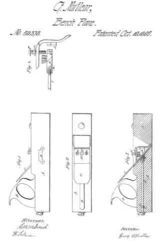
Figure 1 is a top view, Fig. 2 a side elevation, and Fig. 3 a longitudinal section, of a bench-plane provided with my invention. Flg. 4 is a top view of the furcated lever of the mechanism for fastening the plane-iron in place in the stock and on the adjustable bed. Fig. 5 is a front view of the said adjustable bed.

The nature of my invention or improvement consists in the combination as well as in the arrangement of an adjustable bed, and a mechanism, as hereinafter described, for fastening the plane iron in place in the stock and on the said bed, the parts of the said combination being arranged as hereinafter described, and the object or purpose of such invention being to enable the slant or inclination of the plane-iron to be varied in order to vary the width or size of the shaving-mouth at the cutting edge of the plane iron, and thus adapt the plane to the cutting of either thick or thin shavings from a piece of wood or article while being planed.

In the drawings, A denotes the plane-stock, provided with a throat, a, and a plane-iron, B, the latter having a cap iron or plate, C.

The plane iron rests on the lower part, b, of the throat a, and also on an adjustable bearing or bed, G, which is formed as shown in Figs. 3 and 5, screws into the stock, and is arranged in an inclined position, as exhibited in Fig. 3.

By taking hold of the head c of the bed or bearing G, and revolving the bearing, we can either screw it more of less into the stock, so as to vary the distance of the top of the head from the upper surface of the stock.

In advance of the bearing G there is a screw, D, which goes through the plane-iron and its cap-iron, and is screwed into the stock. A forked lever, E, clasps the shank of the screw D, and directly underneath the head d thereof, and has a screw, F, screwed through it and against the cap-iron G, the lower end of the said lever E being in contact with the cap-iron.

The adjustable fulcrum-screw D, the furcated lever E, and the screw F, constitute the mechanism for fastening the plane-iron in the stock or in the latter and to the bearing G. This fastening mechanism I do not claim as my invention by itself, or irrespective of the adjustable bearing G.

By the use of the said fastening mechanism no wedge is required to hold the plane in the stock. Consequently there will be no danger of splitting the stock, such as is incident to the wedge. The adjustable bearing G enables the shaving-mouth to be increased or diminished, as circumstances may require, and is also advantageous in other respects.

I lay no claim to the invention ofthe mechanism as above described for fastening the plane iron in the stock, such mechanism consisting of the screw D, the lever E, and the screw F, arranged with respect to the plane-stock and the plane iron or irons as described. Nor do I claim an adjustable bed as combined with stationary supports of the plane-iron, and constituting with them a means of confining the said plane-iron in its place in the stock, the same being as shown in Asahel G. Batchelder’s application for a patent filed in United States Patent Office on or about the 3d day of July, A. D. 1857, and subsequently rejected. My invention not only differs from those above cited as well in the structure as in the arrangement of its parts, but possesses one or more advantages not incident to them. In other words, while it retains all those of the fastening mechanism above mentioned, it has another which results from the adjustable bed not being required to be revolved in order to effect the fastening of the iron in the stock to be varied, such angle being for all practical purposes constant in the said Batchelder’s plane. I thus have the double advantage of not only varying the angle of inclination of the plane-iron, but of being capable of so springing the iron as to vary the breadth of the shaving-mouth of the throat as circumstances may require.

I claim —

1. The combination of the adjustable bed or bearing G, the screws F and D, and the lever E, the whole being arranged with respect to the plane-iron and the stock substantially as specifed.

2. The arrangement of the adjustable bed G, with the fulcrum-screw D, the lever E, the screw F, the plane-iron B, and its bearing b, arranged at the lower part of the throat a, as described.

WING H. TABER.

Witnesses:
J. N. MARSHALL,
JOEL A. ABBOTT.

No. 50,378 – Improvement In Bench Planes (George Müllear) (1865)

[paiddownloads id=”107″]50378


UNITED STATES PATENT OFFICE.

_________________

GEORGE MÜLLEAR, OF SAN FRANCISCO, CALIFORNIA.

IMPROVEMENT IN BENCH-PLANES.

_________________

Specification forming part of Letters Patent No. 50,378, dated October 10, 1865.

_________________

To all whom it may concern:

Be it known that I, GEORGE MÜLLEAR, of the city and county of San Francisco, and State of California, have invented certain new and useful Improvements in Carpenters’ Planes; and I do hereby declare that the following description and accompanying drawings are sufficient to enable any person skilled in the art or science to which it most nearly appertains to make and use my said invention or improvements without further invention or experiment.

The nature of my invention and improvement in planes consists in clamping the cutting-bit and turning the shaving cut by means of a metal cap drawn against the bit by a screw in the rear cf the plane-stock, and in making the clamping-cap adjustable horizontally by means of brackets, grooves, and adjusting-screws.

In the accompanying drawings, Figure I is an elevation of a plane with my improvements. Fig. 2 is a plan or top view. Fig. 3 is a section of the plane cut perpendicularly length-wise. Fig. 4 shows some of the parts enlarged and separate from the stock.

In these drawings, A is the plane-stock, B the handle, and C the cutting-bit, all of which are made in the form in common use by mechanics.

A mortise is made entirely through the stock horizontally for the traversing block M, which is fitted to traverse in it and moved by the screw I, which extends back through the rear of the stock and is provided with a collar, K, and there is a pin, L, through the stock behind the collar to prevent the screw from corning out when it is turned to traverse the block M. This block M is provided with two arms, R, which extend forward each side of the bit C and are perforated for screws which screw through the arms into the block N, which is properly the front part of the block M, as they are both traversed together by the screw I. The block N has two perpendicular grooves, P, for the flanges S of the brackets O on the cap H to traversein when the cap H is raised by the screw F or drawn down by the screws G G, which pass through the cap and screw into the block N, the screw F screwing through the cap onto the block N, and the screws G G passing through the cap and screwing into the block N, so that by turning the screws the cap may be adjusted higher or lower on the bit. The cap H is made in the form shown in Figs. 3 and 4, and bent so that both ends bear or press upon the bit C to clamp it in the stock and hold it in its place while the plane is used.

The head E of the screw I fits against the end ofthe stock A, so that by turning the screw I the blocks M and N, with the cap H, are drawn back toward the rear of the plane and the cap H presses upon the bit C and clamps it fast and holds it in position upon its bed in the stock while the plane is used; and the loweredge ofthe cap H may be adjusted higher or lower on the bit by turning the screws F and G so as to turn the shavings cut by the bit more or less short as they are cut. There is a brass plate, D, fitted into each side cf the plane and fastened by screws to cover the mortise occupied by the block M in the stock.

I contemplate that the traversing blocks M and N may both be made in one piece of malIeable iron, if preferred that way.

Having described my improvements, I claim —

I. The screw I, traversing blocks M and N, and cap H, for clamping and holding the bit and turning the shaving cut, substantially as described, whether the cap is made adjustable horizontally or otherwise.

2. Making the cap H adjustable higher or lower onthe cutting-bit by means of the brackets O, grooves P, and screws F and G G.

GEORGE MÜLLEAR.

Witnesses:
C. W. M. SMITH,
H. SAKEMAN.

No. 50,530 – Improvement In Bench Planes (Lyman C. Bliss) (1865)

[paiddownloads id=”108″]50530


UNITED STATES PATENT OFFICE.

_________________

LYMAN C. BLISS, OF RICHMOND, INDIANA, ASSIGNOR. TO LYMAN C. BLISS AND JOHN GRIFFITH.

IMPROVEMENT IN BENCH-PLANES.

_________________

Specification forming part of Letters Patent No. 50,530, dated October 17, 1865.

_________________

To all whom it may concern:

Be it known that I, LYMAN C. BLISS, of Richmond, in the county of Wayne and State of Indiana,have made new and useful Improvements in Bench-Planes; and I do hereby declare the following to be a full, clear, and exact description of the nature, construction, and operation of the same, sufficient to enable one skilled in the art to which it appertains to construct and use the same, reference being had to the accompanying drawings, which are made part of this specification, and in which —

Figure 1 is a View of the under side or face of the plane. Fig. 2 is a longitudinal vertical section on the line x x, Figs. 1 and 3. Fig. 3 is a transverse vertical section on the line y y, Figs. 1 and 2.

The same letters refer to corresponding parts in the different figures.

The invention consists in the adaptation to and arrangement in the tool of the jointer and slat-cutting plane.

A is the stock ofthe plane; and B,a strip which is fastened to the face of the plane, acting as a guide and separating the bits., The side C of the plane is occupied by the jointing-bit D, of ordinary construction, and the other side of the plane is faced with plates E and F, the former of which passes from the hind end of the plane to the back edge of the bit G, while the other, starting from the forward end of the plane, is partially overlapped by the oblique edge of the plane-bit G. The bit G is secured by means of a bolt, H, which passes through the slot in the rear edge of the bit and also through an orifice in the plate F, which on its rear edge is divided. The portion f of the plate, or that immediately over the longitudinal channel I in the face of the plane-stock, is cut diagonally, so as to present a yielding edge parallel with the cutting-edge of the bit, which overlaps it.

The operation is as follows: The jointing-bit D being first brought into action, the board from which the strip, splint, or slat is to be cut is straightened, when the plane is shifted so as to bring the other side into action, the sliver cut by the bit G pressing back the tongue f of the plate F, and passing out by the way of the channel I, to be discharged at the rear end ofthe plane. The splint or slat being separated from the edge of the board by the draw-cut of the bit G, leaves the said splint smoother and without cracks.

Having described my invention, what I claim therein as new, and desire to secure by Letters Patent, is —

As an article of manufacture, a bench-plane constructed, as described, with a jointing-bit and a draw-cut splint-cutting bit on the opposite sides of the dividing-strip on the face of the plane.

LYMAN O. BLISS.

Witnesses :
JOHN FINLEY,
THOS. A. DUGDALE.

No. 50,947 – Improvement In Splint Planes (Harrison Ogborn) (1865)

[paiddownloads id=”109″]13957


UNITED STATES PATENT OFFICE.

_________________

HARRISON OGBORN, OF RICHMOND, INDIANA.

IMPROVEMENT IN SPLINT-PLANES.

_________________

Specification forming part of Letters Patent No. 50,947, dated November 14, 1865.

_________________

To all whom it may concern:

Be it known that I, HARRISON OGBORN, of Richmond, in the county of Wayne and State of Indiana, have invented certain new and useful Improvements in Planes for Cutting Blind-Slats, Splints for Baskets, and other similar work; and I do hereby declare that the following is a full, clear, and exact description of the construction and operation of the same, reference being had to the annexed drawings, made a part of this specidcation, and the letters of reference thereon, the same letters referring to identical parts.

Figure 1 is a side view of the plane when arranged for use as a jack-plane, showing the bottom of the plane used for cutting slats, &c.
Fig. 2 is a longitudinal vertical section of the plane through the line y y, Fig. 4. Fig. 3 is a like section through the line x x, Fig. 4. Fig. 4 is a transverse section of the stock. Fig. 5 is a view of the knife employed for splitting the slats or splints. Fig. 6 is a view of a knife for splitting the slats with beveled edges. Fig. 7 shows the adjustable plate for determining the cut and removing splinters that wedge in the plane. Fig. 8 is a sectional view of the knife or bit used on the splint-plane. Fig. 9 is a top view of the same.

The stock of the plane A is arranged for two bits, and having two faces. One of these is an ordinary jack-plane, as shown in Figs. 1 and 2.

The handle B is adjustable, and may be made to stand perpendicularly to either of the plane-faces. It turns upon a rod, M, and, swinging in a notched recess in the corner of the stock, is held perpendicularly to either face by an ordinary window-catch, of which there are two shown, Figs. 2 and 3, G G’.

On the bottom of the face of the splint-plane are shown two adjustable guides, one square, the other beveled. One of these, according to the character of the work, is used on the left-hand side of the plane, held in place by screws with oblong heads working in slots in the ends of the guides, as shown in Fig. 1.

D is the knife or bit ofthe splint-plane, held in place by the same kind of screws working in slots, so as to allow the adjustment of the knife by the aid of the set-screws N N.

E shows the bit of the jack-plane, of ordinary construction, and arranged in the usual manner.

K is an adjustable plate, held by similar screws on the face, allowing its adjustment to the knife as they are worn away in use, to which is attached the set-screw passing through the stock and working in a collar on the upper surface of the plane. This arrangement makes it easy to withdraw the plate in case a splinter should wedge in the space between the plate and knife.

The knives H I, one straight, the other bent for cutting beveled edges, work as shown in Figs. 3 and 4. The knives are held in place by the wedge L, and the points protrude through narrow slots in the plate K. (Shown in Fig. 1.) The bent knife its the beveled point of the wedge L. When the straight knife is used the wedge goes on the right of it, but on the left side of the bent knife. There are one or more of these knives used, according to the number of slats intended to be cut from the board. The bent knife is used with the beveled guide.

In operating with this plane, the boards, being dressed, are cut into narrow strips of the proper width on their edges by the knife H, or so that the slats shall have beveled edges, by the knife I. The splints are cut by the knife or bit D passing between the plate K and the bit D. Rising over D, they are bent in a contrary direction, and passing out under the lower surface of the plane they are flattened and delivered free from curves or tendency to twist.

Having thus fully explained the character and operation of my improvements, what I claim as my invention, and seek to secure by Letters Patent, is —

1. The arrangement, in a splint-plane, of the plate K, bit D, and one or more splitting-knives, and guide C, all constructed and combined substantially as and for the purpose set forth.

2. The arrangement, in a splint-plane, of the piate K, bit D, beveled guide C and one or more bent knives, I, all constructed and combined substantially as and for the purposes set forth.

3. The combination of the plane-stock A and adjustable handle B, so constructed with the rod M and springs G and G’ as to be capable of being arranged perpendicularly to the two faces of the plane, substantially as described. In testimony whereof I have signed my name to this specifcation in the presence of two subscribing witnesses.

HARRISON OGBORN

Witnesses:
R. MASON, BEN FIELD.

No. 51,153 – Improvement In Splint Planes (James Dempsey) (1865)

[paiddownloads id=”110″]51153


UNITED STATES PATENT OFFICE.

_________________

JAMES DEMPSEY, OF RICHMOND, INDIANA.

IMPROVEMENT IN SPLINT-PLANES.

_________________

Specification forming part of Letters Patent No. 51,153, dated November 28, 1865.

_________________

To all whom it may concern:

Be it known that I, JAMES DEMPSEY, of Richmond, in the county of Wayne and State of Indiana, have invented certain new and useful Improvements in Planes for Cutting Slats for Window-Shades or other Thin Splints of Wood.

The object of my invention is to construct a splint-plane that shall be as readily adjustable as the ordinary hand-plane, and have such a channel for the splint when out as that it shall not be broken by being thrown abruptly upward over the knife. In other planes either the splint is liable to be broken or the knife placed horizontally is ditiicult of adjustment. Another object is to provide that the splint when cut shall be perfectly smooth and fit for use as it comes from the plane. Both of these objects are, I believe, accomplished by my im-provements.

To enable others skilled in the art to make and use my invention, I will describe its construction and operation, reference being had to the annexed drawings, making a part of this specification, and the lettering thereon.

In the different plans the same letters refer to identical parts.

Figure 1 is an elevation showing the half of the plane when divided into two parts, on the line x x, Fig. 3, where the plane as constructed is divided. Fig. 2 is a longitudinal section on the line x x, Fig. 3. Fig. 3 is a transverse section upon the line y y, Fig. 4. Fig. 4 is a plan of the plane, showing the bottom part, the guide being represented as cut away in part. Fig. 5 is a plan showing the construction of the bit. Fig. 6 is a plan showing the construction of the spring in the bottom of the plane.

The stock is made in two parts, A and B, of wood, joined by the dowel-pins L L and by screws.

C is the bit, of which about two inches of the lower end is nearly horizontal, but depressed at the point sutliciently to give the cutting-edge the requisite draft into the wood. It is bent at N, rising and passing transversely through the stock. It is adjusted by the set-screw H, and held firmly in place by the wedge M and clamps E E. These clamps catch upon the bit below and hold it firmly by stress of the nuts E’ E’ upon their upper ends. This bit is constructed with the rectangular slot G, which opens from the angle and extends upward about three inches, and having a width of about seven-eighths (7/8) of an inch. Over this slot the spring G is placed, bent upward and having the upper extremity, near O, turned slightly down, so as to hold firmly to the splint as it passes, and yet guide it through the slot at O. Upon the bottom of the plane, attached by a set-screw working in the slot F, is the spring D, the tongue extending above the bit and forming a guide for the splints as cut. On the bottom of the side B of the stock is fastened a guide, P, made adjustable by the set-screws and slots K.

On the under side ofthe wedge M, at its lower extremity, is cut a groove, of the width of the slot in the bit C, and terminating a little above the point ofthe spring G. Through this groove passes the splint.

In operating with the plane the guide p is set at one-half the width of the splint to be cut from the line x x. The bit C and spring D being adjusted by the set-screws I and H to cut splints of the required thickness, the bit C is held firmly in place by the wedge M and clamps E. The splint, being cut by the sharp point of the bit, rises above it, passing under the tongue of the spring upward through the groove in the under side of the wedge M, over the spring G. It passes through the bit C at O, and is carried through the stock in the groove D, passing out behind the plane unbroken and highly polished by the combined action of the cutter-bit and spring.

Having fully explained my mode of constructing and operating splint-planes, what I claim as my invention, and seek to secure by Letters Patent, is —

1. Constructing the bit C of a splint-plane with the slot and spring, substantially as described.

2. The arrangement of the spring D, clamps E, wedge M, stock A B, with the bit C, all of them constructed and combined substantially as and for the purpose described.

In testimony whereof I have signed my name to this specification in the presence of two subscribing witnesses.

JAMES DEMPSEY.

Witnesses:
R. MASON,
JOHN S. HOLLINGSHEAD.

No. 51,339 – Improvement In Spokeshaves (Silas S. Mowry And Albert G. Bates) (1865)

No. 51,339 – Improvement In Spokeshaves (Silas S. Mowry And Albert G. Bates) (1865)

[paiddownloads id=”111″]51339


UNITED STATES PATENT OFFICE.

_________________

SILAS S. MOWRY AND ALBERT G. BATES, OF PROVIDENCE, RHODE ISLAND.

IMPROVEMENT IN SPOKESHAVES.

_________________

Specification forming part of Letters Patent No. 51,339, dated December 5, 1865.

_________________

To all whom it may concern:

Be it known that we, SILAS S. MOWRY and ALBERT G. BATES, both of the city and county of Providence, in the State of Rhode Island, have invented a new and useful Improveinent in Spokeshavers; and we do hereby declare that the following specification, taken in connection with the drawings, making a part of the same, is a full, clear, and exact description thereof.

Figure 1 is a perspective view. Fig. 2 is a transverse section.

Our improvement has reference to a means for readily adjusting or removing the cutter, so that without loss of time the same can be removed to be sharpened, and be readjusted in place, While at the same time the advantage is secured of being able to make use of the plane-iron so long as there is enough of it left to be held in the stock.

In the accompanying drawings, A, Fig. 1, is the stock of the shaver, constructed with handles B B at the sides in the usual way. It is provided with a stationary iron, G, held by the screws a,a, passing through slots in the iron, so as to admit of adjustment for a finer or coarser cut of the knife, as desired, and thereby give all the advantages of the double plane-iron.

D is the knife or cutter, which is placed at the proper angle in the stock, as determined by the height of the rear portion, b, against which it bears.

The knife is held firmly in the desired position with reference to the stationary iron C by means of two turn-buckles, E E, which turn upon the shanks of the screws a a, which hold the upper iron, as already mentioned. These turn-buckles have the portion which lies between the under surface of the stationary iron and the upper surface of the cutting-iron wedge form, so that when the same are pushed forward they will hold the cutter firmly in place.

It is obvious that the cutter can be removed by turning back these wedge-form pieces, and relieving it from the pressure by which it is held. lt is also apparent that by this method of construction no slot is required in the cutter for the accommodation of a set-screw to hold it in the stock, as is the case in the irons of most shaves; but the same can be used until ground away to within three-eighths of an inch of the back.

What we claim as our invention, and desire to secure by Letters Patent, is —

The use of the two turning wedge-form pieces E E, for the purpose of holding the cutter of
a spokeshaver in its stock, arranged and operating in the manner substantially as described.

ALBERT G. BATES.
SILAS S. MOWRY.

Witnesses:
W. B. VINCENT,
J. D. THURSTON.