No. 81,425 – Improvement In Planes (F. Smith And I. Carpenter) (1868)

[paiddownloads id=”141″]81425


United States Patent Office.


F. SMITH AND I. CARPENTER, OF LANCASTER, PENNSYLVANIA.

Letters Patent No. 81,425, dated August 25, 1868.
_________________

IMPROVEMENT IN PLANES.

_________________

The Schedule referred to in these Letters Patent and making part of the same.

_________________

TO ALL WHOM IT MAY CONCERN:

Be it known that we, F. SMITH and I. CARPENTER, of Lancaster, in the county of Lancaster, and State of Pennsylvania, have invented a new and useful Improvement in Joiners’ Planes; and we do hereby declare that the following is a full, clear, and exact description thereof, which will enable those skilled in the art to make and use the same, reference being had to the accompanying drawings, forming part of this specification.

The nature of our invention relates to improvements in joiners’ planes, whereby it is designed to render the stocks less liable to warp, to regulate the weight of the same, to provide for a more perfect delivery of the shaving, adjusting the some to be used as a single or a double plane, and adjusting the mouth, so as to govern the width of the same for the passage of the shaving.

And it consists in constructing the stock partly of iron, substituting, for the tapered notches of wooden stocks for holding the tightening-wedges, set-screws for holding the wedge, which is made of metal, and provided with an additional tightening-screw in its upper end, which works against the face ofthe plane-bit, or into a swivel-nut which slides in the slots of plane-bits, as ordinarily constructed, and providing a wooden wedge at the back side ofthe plane-bit, as will be more fully described on reference to the accompanying drawings, wherein —

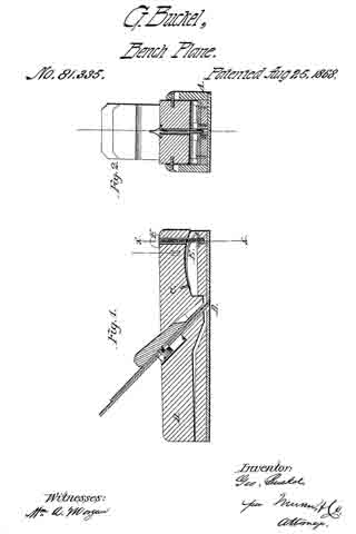
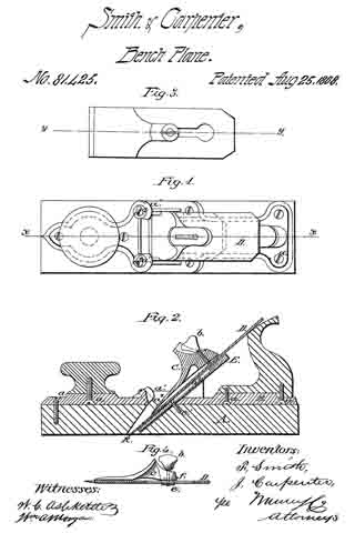
Figure 1 represents a plan view of our improved plane.
Figure 2, a central section ofthe same on the line x x of fig. 1.
Figure 3, a plan view of a part of our improvement applied to plane-bits, having the ordinary slot in the same; and
Figure 4 a section on the line y y of fig. 3.

Similar letters of reference indicate corresponding parts.

A represents the wood part of the stock, and B the iron portion of the same, which are secured together by the screws d d.

The part B may-be made of cast iron, and of different thicknesses, as may be desired to govern the weight of the plane.

The handle and knob may be secured to the part B in suitable sockets provided for them by the screws d d.

The part B is provided with lugs, a1 a1, through which set-screws, a2 a2, are arranged to hold the cap.

C represents a metal cap or wedge, provided with a set-screw, b, by which it may be, if desired, raised at its upper end from the bit D.

The said cap is provided with a raised portion, C’, in advance of the set-screw b, which rises by a gentle curve from the wedge portion of the same, so as to prevent the shavings from clogging against the screw.

When a plane-bit is used without a slot, as in figs. 1 and 2, we use a set-screw arranged as therein shown, but to adapt our improved tightening-wedge to plane-bits of the old construction, having the slot for set-screws as ordinarily constructed, we attach, to the ends of the set-screws, swivel-nuts, e, having slots in two edges of the same, which admit it to slide within the slot in the plane-bit, by taking the edges of the bit forming the side walls of the slot in the latter into the slots in the nut, the nut being of the proper size to be admitted through the enlarged portion of the slot in the plane-bit.

E represents a wedge, which may be made of wood or metal, and arranged in the bottom of the mouth of the stock under the plane-bit, and held there by the set-screw e1 passing through a slot in the said wedge, whereby it may be adjusted within the mouth ofthe stock.

The face of the wedge next the plane-bit is provided with a recess, e2, to admit the nut e of the set-screw.

The under side of the upper end of the metallic wedge C is provided with a recess, f, (see fig. 4,) when the nut e is used.

By the use of our improved wedge, the same plane-bit may be used for a double or single bit.

When used as a single bit, it may be applied as shown in fig. 2, and when used as a double bit, the set-screws a2 may be withdrawn, so that the wedge may be moved down sufficiently near to the edge of the bit to serve the purpose of a double bit.

By adjusting the upper end of the wedge by a set-screw, b, the width of the mouth may be adjusted to suit the different requirements of different kinds of work, or of different kinds of wood, or may be made of uniform width from bottom to top.

The same may be also adjusted by the wedge E to some extent, but the more important function of the wedge E is to govern the width of the throat at the cutting-edge of the bit, as at k, as will be readily understood.

In adjusting the wedge to the bit, when constructed as shown in figs. 3 and 4, the lower end of the wedge is placed at the right position with reference to the cutting-edge of the bit, and the thumb-screw turned to the left until the upper end of the wedge is screwed tightly to the bit. They are then inserted in the stock, the set-screws a2 adjusted to their right positions, when the set-screw b is turned in the opposite direction, and the wedge forced out against the set-screws a2.

The metallic part, B, of our stock may be taken off from a worn-out wood stock, and readily applied to a new one, or old plane-stocks of ordinary construction may be readily fitted to be attached to it.

We claim as new, and desire to secure by Letters Patent —

1. The adjustable cap, provided with the guard in front of the set-screw b, substantially as and for the purpose described.

2. The set-screws a2 in the lugs a1, arranged to clamp upon the adjustable wedge C, as herein shown and described for the purpose specified.

F. SMITH,
I. CARPENTER.

Witnesses:
P. G. EBERMAN,
F. R. GRUGER.

No. 81,335 – Improvement In Planes (George Buckel) (1868)

[paiddownloads id=”140″]81335


United States Patent Office.


GEORGE BUCKEL, OF DETROIT, MICHIGAN.

Letters Patent No. 81,335, dated August 25, 1868
_________________

IMPROVEMENT IN PLANES.

_________________

The Schedule referred to in these Letters Patent and making part of the same.

_________________

TO ALL WHOM IT MAY CONCERN:

Be it known that I, GEORGE BUCKEL, of Detroit, in the county of Wayne, and State of Michigan, have invented a new and improved Plane; and I do hereby declare that the following is a full, clear, and exact description thereof, which will enable those skilled in the art to make and use the same, reference being had to the accompanying drawings, forming part of this specification.

The object of this invention is to provide a plane so arranged that the out may be regulated either in a positive manner or by the pressure of the hand, and that the bit may be raised out of contact with the board being operated on when it is being moved back.

It consists in making the stock in two parts, one part, which supports the bit, being pivoted at the rear end in a longitudinal channel through the other, and provided with a spring and adjusting-screw at the other end, the springs being so arranged as to throw the bit out of contact with the board when the pressure of the hand is removed, and the set-screw governs the amount of such movement.

Figure 1 represents a longitudinal sectional elevation of my improved plane, and
Figure 2 represents a transverse section on the line x x of fig. 1.

Similar letters of reference indicate corresponding parts.

A represents one part of the stock, which is provided with a deep and wide channel in the upper portion from end to end, as clearly shown in fig. 2, and with an opening through the bottom for the plane-bit, as shown at B.

C represents the other part of the stock, which is fitted to the channel in the part A, and pivoted thereto at the rear end, as shown at D.

It is provided with the usual opening for the plane-bit and wedge, and for the escape of the shavings, and at the front end with a spring, E, in a recess in the under face of the same. The said spring bears upon the bottom of the channel, and has a constant tendency to raise the part C away from the said bottom of the channel.

F represents a set-screw, which screws into a nut in the bottom of the channel in the part A, and arrests the upward movement of the part C, due to the action of the spring. The said screw may be adjusted to regulate the said movement of the part C, as desired.

The plane-bit being set by the wedge in the part C as desired, the operator, in using the plane, may, on shoving it forward, so press down the front end of the part C as to cause the bit to take the full cut for which it is set, or, by a lighter pressure, take but a part of the said cut, and when the cut has been made, and the pressure necessary for making the same is relaxed, the spring will throw the part C up so as to take the edge of the bit out of contact with the surface being planed while the plane is being drawn back, thereby protecting the edge from being worn round from that cause.

I claim as new, and desire to secure by Letters Patent —

A plane-stock, constructed of the parts A and C, pivoted together, and provided with a spring, E, and set-screw, F, substantially as and for the purpose set forth.

The above specification of my invention signed by me, this eighth day of July, 1868.

GEORGE BUCKEL.

Witnesses:
JOSEPH KUHN,
CHARLES STARKLOFF.

No. 80,917 – Improvement In Coopers’ Croze (Charles O. Cook) (1868)

[paiddownloads id=”139″]80917


United States Patent Office.


CHARLES O. COOK, OF ROCKFORD, ILLINOIS, ASIGNOR TO HIMSELF AND R. R. BLAISDELL.

Letters Patent No. 80,917, dated August 11, 1868.
_________________

IMPROVEMENT IN COOPERS’ CROZE.

_________________

The Schedule referred to in these Letters Patent and making part of the same.

_________________

TO ALL WHOM IT MAY CONCERN:

Be it known that I, CHARLES O. COOK, of Rockford, in the county of Winnebago, and State of Illinois, have invented a new and improved Coopers’ Croze; and I do hereby declare that the following is a full and exact description of the same, reference being had to the accompanying drawings, and to the letters of reference marked thereon.

This invention relates to certain improvements in coopers’ croze, and consists in a simple construction of the cutting-iron, whereby it is readily attached to and detached from the adjusting-screw when desired, and yet is securely held when in use, as will be described hereinafter.

Figure 1 represents a plan view of my invention, and
Figures 2, 3, and 4 represent views of parts detached.

In the drawings —

A represents the main part of the instrurncnt, the outer edge of which is curved, to dt the inside of a barrel, and is V-shaped, as shown.

a represents a socket or groove running diagonally across it, in which iits the upper part of the cutting-iron B, which latter is made of proper form to slide easily therein.

b represents an arm extending from the upper end of the cutting-iron B, as shown, upon which is placed the shoulder b1.

b2 represents a flat spring fastened to the lower side of the iron, and extending out in line with shoulder b1.

By this arrangement a socket is made in which rests the button of screw C. The lower or cutting part of the instrument is made V-shaped, for the purpose of cutting the groove in the staves. If desired, this part may be made square in forrn, for the purpose of cutting a corresponding groove.

C represents a screw, the button of which its into the socket of the cutter B, as before described, and revolves freely therein.

c c represent its bearings, provided with corresponding screw-threads. By turning the screw C, the cutter is thrust forward or drawn back, as may be desired.

D represents another screw, placed above the cutter, and operated sirnilarly to C, excepting that it is not attached in any way to the cutter. A bearing-surface of different metal may be used if desired, for the cutter to slide upon, but this is not essential.

This instrument should be attached to the wooden guide, constructed as usual, by means of the lugs x x.

From this description the operation of my invention will be readily understood. The iron is easily attached to the screw by simply pushing the former forcibly against b2 and shoulder b1, in which case the spring b2 yields sufficiently to permit the head of the screw C to pass by the shoulder b1 and rest in the socket. When it is desired to detach the iron for any purpose, its free end should be pulled up from the croze (the holding-screw having been loosened) far enough to force spring b2 open, by which means the head of screw C is permitted to slip out. The cutter B is adjusted in or out, as may be desired, by means of the screw C, after which the screw D is set down upon it, by which means the cutter is rigidly held in place.

This construction allows the cutter to be quickly and easily detached, while at the same time it is firmly held when in use.

Having thus fully described my invention, what I claim as new, and desire to secure by Letters Patent, is —

The arm b, shoulder b1, and spring b2 of cutting-iron B, when combined and operated in connection with the head of screw C, as and for the purpose described.

This specification signed and witnessed, this third day of April, 1868.

CHARLES O. COOK.

Witnesses :
OLIVER A. PENNOYER,
G. W. FORD.

No. 77,434 – Improvement In Splint-Planes (D.E. Aiken And A.A. Aiken) (1868)

[paiddownloads id=”138″]77434


United States Patent Office.


D. E. AIKEN AND A. A. AIKEN, OF ADRIAN, MICHIGAN.

Letters Patent No. 77,434, dated May 5, 1868.
_________________

IMPROVEMENT IN SPLINT-PLANES.

_________________

The Schedule referred to in these Letters Patent and making part of the same.

_________________

ALL WHOM IT MAY CONCERN:

Be it known that we, D. E. AIKEN and A. A. AIKEN, of Adrian, in the county of Lenawee, and State of Michigan, have invented a new and improved Plane; and we do hereby declare that the following is a full, clear, and exact description thereof, which will enable others skilled in the art to make and use the same, reference being had to the accompanying drawings, forming part of this specification.

The present invention relates to a new and improved plane, or machine for the cutting of slats to be used more particularly in making curtains; and the invention consists in making the throat of the cutter in the wedge, and also in the use of a spring within the throat, so constructed as to cause one slat to push another out, whereby the throat and bit are left free, and all danger of the throat becoming clogged rendered impossible.

This spring also acts to press the slat uniformly and closely up against the bit, thus leaving the slat smooth and straight, and is arranged so as to be susceptible of adjustment for thick or thin slats.
In the accompanying plate of drawings our improved plane is illustrated —

Figure 1 being a central longitudinal vertical section through the plane,
Figure 2 a plan or top view, and
Figure 3 a view of the plane at one end.

Similar letters of reference indicate corresponding parts.

A, in the drawings, represents the stock to the plane made upon its running-face of a right-angular shape, as shown in fig. 3 by an end view.

B, the cutter arranged in the stock A, as in ordinary planes, and there secured by driving a wedge, C, into the stock over the cutter, this wedge being cut out upon its under side to form or leave a passage or throat, D, between it and the top ofthe cutter B.

E, a bent spring secured in wedge C along its under side, with its loose end toward the opening F in the running-surface of the plane, which spring is susceptible of adjustment by means of a set-screw, G, in the wedge C, in proper position to bear therein.

Among the many advantages of our improved plane or slat-cutter may be here mentioned that for the following reasons it is superior to all others:

It is simple, cheap, and easily kept in order, runs remarkably easy, makes a superior slat, lighter, smoother, and more durable than any other, producing what is called a wafer-slat, which is more durable, for the reason that it does not cut the thread used in forming the slats into curtains.

We claim as new, and desire to secure by Letters Patent —

The wedge C of the plane provided with a longitudinal groove in its under side, in which is secured one end of the spring E, whose free end is adjusted to regulate the thickness of the slat to be cut by the screw G passing through the wedge, all constructed, arranged, and operating as described for the purpose specified.

D. E. AIKEN,
A. A. AIKEN.

Witnesses:
A. M. ALLEN,
C. B. JOHNSON.

No. 74,757 – Improved Work-Trimmer For Boots And Shoes (A.V. Hill) (1868)

[paiddownloads id=”136″]74757


United States Patent Office.


A. V. HILL, OF LIMESTONE, NEW YORK.

Letters Patent No. 74,757, dated February 25, 1868; antedated February 12, 1868.
_________________

IMPROVED WORK-TRIMMER FOR BOOTS AND SHOES.

_________________

The Schedule referred to in these Letters Patent and making part of the same.

_________________

TO ALL WHOM IT MAY CONCERN:

Be it known that I, A. V. HILL, of Limestone, in the county of Cattarangus, and State of New York, have invented a new and improved Work-Trimmer; and I do hereby declare that the following is a full, clear, and exact description thereof, which will enable others skilled in the art to make and use the same, reference being had to the accompanying drawings, forming part of this specfiication.

This invention relates to an improved work-trimmer used chiefly in making ladies’ boots and shoes; and consists in a blade, of trapezoidal form, having a rectangular shank, bent at right angles to the blade, inserted in a slotted head. In the accompanying drawings —

Figure 1 is a top view, and
Figure 2 an end view of my improved trimmer.

Similar letters of reference indicate like parts.

A is the slotted head set in the socket in handle H. The trapezoidal blade B is provided with a rectangular shank b, bent to it at right angles, and held adjustably in the slotted head A. A small lip at c serves as a guard.

In trimming work with any ordinary trimmer, the tool has to he worked from the body By applying the guard, c between the sole and upper, and drawing to the body, the blade pares the sole and cuts the welt-edge without any risk of cutting the upper, and with very much less exertion on the part of the workman.

What I claim as new, and desire to secure by Letters Patent, is —

1. The guard c, when applied to a work-trimmer, in manner and for the purposes substantially as described.

2. The blade B, fitted adjustably into a head, A, by the shank b, as herein set forth, and for the purposes substantially as described.

A. V. HILL.

Witnesses:
SHEP. L. VIBBARD,
FRANK COOK.

No. 73,723 – Improvement In Spoke-Shaves (Seth T. Hutchins) (1868)

[paiddownloads id=”135″]73723


United States Patent Office.


SETH T. HUTCHINS, OF NORTH ANSON, MAINE, ASSIGNOR TO HORACE A.
LATHROP, OF SHARON, MASSACHUSETTS.

Letters Patent No. 73,723, dated January 28, 1868.
_________________

IMPROVEMENT IN SPOKE-SHAVES.

_________________

The Schedule referred to in these Letters Patent and making part of the same.

_________________

TO ALL PERSONS TO WHOM THESE PRESENTS MAY COME:

Be it known that I, SETH T. HUTCHINS, of North Anson, in the county of Somerset, and State of Maine, have invented a new and useful Improvement in Heel or Spoke-Shaves; and I do hereby declare the same to be fully described in the following specification, and represented in the accompanying drawings, of which —

Figure 1 is a. top view,
Figure 2 a bottom view, and
Figure 3 a side elevation of a spoke or heel-shave provided with my improvement.

In carrying out my invention, I not only make the adjustable throat-piece or gauge separate from two buttresses, so applied to the stock as to be capable of being moved or adjusted thereon, in order to properly adjust the throat-piece relatively to the knife or cutter, but I hinge the throat-piece to one of the said buttresses in a manner to enable the throat-piece to be turned aside or away from the knife, in order to allow the latter to be sharpened, as occasion may require; the adjusting abutments of the throat-piece remaining in the mean while undisturbed in their positions relatively to the stock. After the sharpening of the knife may have been effected, the restoration of the throat-piece to place against the abutment, away from which it was moved, can be accomplished, by simply turning the throat-piece down thereupon.

In the drawings, A denotes the stock, made in the usual form, and having two handles a a. B is the knife or cutter, fastened in or to the stock, C is the gauge, and D E its two adjustable abutments, each of the latter being held to the stock by means of a clamp-screw, b, going through a slot made in such abutment; the same being so as to enable the distance of the gauge or throat-piece C from the cutting-edge ofthe knife to be either increased or diminished, as circumstances may require. The gauge C is hinged, at or near one extremity, to the abutment E, and at its other end it bears against the other abutment, which is formed with a shoulder or bearing-surface for the gauge to rest on. This application of the gauge enables it to be moved from the abutment D into the position denoted by the dotted lines at G’ in fig. 3.

I do not claim merely applying the gauge to the stock, so as to be adjustable or capable of being adjusted nearer to or further from the knife, in order to either increase or diminish the chip-throat or passage between the knife and the gauge; but

1. I do claim the combination of the separate abutments D E, applied to the stock A, so as to be adjustable, in manner as described, with the gauge C hinged to one of such abutments, and being separate from the other, and to operate with respect to it substantially as explained.

2. I also claim the application of the gauge to its adjusting-devices, so as to be removable from them or either of them, and the knife, when the means of the adjustment of the gauge is held stationary relatively to the stock, as described.

SETH T. HUTCHINS.

Witnesses :
R. H. EDDY,
SAMUEL N. PIPER.

No. 81,879 – Improvement In Planes (Alfred H. Comp) (1868)

[paiddownloads id=”143″]81879


UNITED STATES PATENT OFFICE.

_________________

ALFRED H. COMP, OF MOUNT JOY, PENNSYLVANIA.

IMPROVEMENT IN PLANES.

_________________

Specification forming part of Letters Patent No. 81,879, dated September 8, 1868.

_________________

To all whom it may concern:

Be it known that I, ALFRED H. COMP, of Mount Joy, in the county of Lancaster and State of Pennsylvania, have invented a new and Improved Device for Adjusting the Width of the Mouth in Smoothing and other Planes; and I do hereby declare that the following is a full, clear, and exact description of the construction and operation of the same, reference being had to the accompanying drawings, making a part of this specification, in which —

Figure 1 shows the application of my adjusting-plates to the bottom of an ordinary smoothing-plane. Fig. 2 shows the plates separated; Fig. 3. the same reversed; Fig. 4, both plates joined, showing the outer face; Fig. 5, the same, showing the inner face and rear-edge view.

The nature of my invention consists in the construction of a dovetailed plate, T-shaped, operated by a horizontal screw, and inserted flush with the wood in the bottom or face of the plane before the mouth, and so as to regulate the width or opening of the mouth at pleasure.

To enable others skilled in the art to make and use my invention, I will proceed to describe the same.

Figs. 2 and 3 clearly show the two plates and appliances B B’.

The bed-plate has a central open space with beveled sides and slide-bearings, the sides of one end slotted or perforated for screws. The other end has a raised flange, E, perforated for a thumb or ordinary cut-headed screw-bearing, as also a screw-hole for attaching against the end of the plane, flush with the wood. The adjusting or sliding T-plate A fits into the space and beveled sides, and is provided with a raised flange, D, having a perforation cut with a thread for the screw C, which is held by a pin or key, K, in the outer flange E on plate B. By this screw C the adjusting-plate A is pushed out or drawn in. Both plates are smooth, and flush on the face with the wood when closed up, as shown by Fig. 4. The same in Fig. 1 is shown pushed out to narrow the mouth.

It is well known that hard and cross-grained or green wood is apt to tear in and get rough when the mouth of the plane is wide, as it should be, for dry and .soft wood, to deliver the shavings freely, and by narrowing the mouth the same plane is equally well adapted, and can be, in fact, regulated with ease, for any kind of wood.

This device can be easily affixed to ordinary planes, and requires no special construction of the throat, as in inventions such as Patent No. 14,436, (1856,) or No. 43,053, (1864,) for bench-planes, where a slotted wedge is used in the throat by means of a set-screw and the like, which differ substantially from my combined plates and screw inserted in the bottom of the plane, as set forth.

What I claim as my invention, and desire to secure by Letters Patent, is —

The beveled sliding plate A and beveled grooved plate B B, with their screw-bearings, when constructed to operate in the manner and for the purpose specified.

A. H. COMP.

Witnesses:
J. GERHART METZGER,
C. M. MARTIN.

No. 82,074 – Improvement In Planes (Valentin Bitsch) (1868)

[paiddownloads id=”144″]82074


United States Patent Office.


VALENTIN BITSCH, OF ST. LOUIS, MISSOURI.

Letters Patent No. 82,074, dated September 15, 1868.

_________________

IMPROVEMENT IN PLANES.

_________________

The Schedule referred to on these Letters Patent and making part of the same.

_________________

TO ALL WHOM IT MAY CONCERN:

Be it known that I, VALENTIN BITSCH, of St. Louis, in the county of St. Louis, and State of Missouri, have made certain new and useful Improvements in Planes for working slats for Venetian window-blinds; and I do hereby declare that the following is a full and clear description thereof, reference being had to the accompanying drawings, and to the letters of reference marked thereon.

The object of this invention is to provide a plane suitable in every respect for cutting the thin, narrow strips used in the construction of Venetian window-blinds, from boards applicable to the purpose.

The plane is so constructed that both edges of the slats are bevelled off on both sides to a feather-edge, for the purpose of fitting the slats so as not to cut or rupture the cords that form the warp, when the blind is rolled up. Formerly, the edges of blind-slats for this kind of blinds were made square, and in rolling up and unrolling the blinds, the cords that formed the warp were abraded and soon ruptured across the square corners. It is to remedy these evils that the present form of plane is constructed.

To enable those skilled in the art to make and use my improved plane, I will proceed to describe its construction and operation.

Figure 1 of the drawings is a side elevation of one of the improved planes.
Figure 2 is an end elevation of the same.
Figure 3 is an elevation of one of the plane-bits.
Figure 4 is an elevation of the other plane-bit.

The plane-stock A is provided with a handle, A’, in the usual manner, and its section is somewhat in the form of a rabbet-plane, as is shown in fig. 2. There are two plane-bits, a a’, fixed in the stock A, as is clearly shown in fig. 1. The plane a is somewhat in advance of the plane a’, and, as is shown in fig. 3, its cutting-edge is somewhat V-shaped, the salient point of the V forming a re-entering angle directed up into the body of the plane, thus leaving the lower outside corners projecting downward in such positions as to cut off and properly bevel the two top corners of the blind-slat as it passes through the plane. The plane-bit a’ is of a loop-shape, as is shown in fig. 4, and it is intended to cut under the slat and release it from the solid board from which it is cut. This bit may be set deep enough to cut the slat of the required thickness, and it will gauge it of a perfectly uniform thickness. The exterior corners of the cutting-edge of the bit a’ should be elevated, as is shown in fig. 4, for the purpose of bevelling off the two bottom corners of the blind-slat, for the purpose already described.

Having described my invention, what I claim, is —

The combination of the bit a, having its lower cutting-edges to form a re-entering angle, with the open-shank bit a’, having its lower cutting-edges arranged with bevelled corners, acting with the plane-stock A, to form blind-slats, whose narrow edges are chamfered, substantially as set forth.

VALENTIN BITSCH.

Witnesses:
GEO. P. HERTHEL, Jr.,
J. BESCHESTOBILL.

No. 82,424 – Improvement In Planes For Cutting Blind-Slats (R.E. Lowe) (1868)

[paiddownloads id=”145″]82424


UNITED STATES PATENT OFFICE.

_________________

R. E. LOWE, OF UPPER ALTON, ILLINOIS.

IMPROVEMENT IN PLANES FOR CUTTING BLIND-SLATS.

_________________

Specification forming part of Letters Patent No. 82,424, dated September 22, 1868.

_________________

To all whom it may concern:

Be it known that I, R. E. LOWE, of Upper Alton, in the county of Madison and State of Illinois, have invented a new and Improved Rustic-Blind-Slat Plane; and I do hereby declare that the following is a full, clear, and exact description of the construction and operation of the same, reference being had to the accompanying drawings, making a part of this specification, in which —

Figure 1 is a longitudinal vertical section through line x x of Fig. 2. Fig. 2 is a bottom view.

The object of this invention is to construct a simple and easily-adjustable instrument, by which the slats of which rustic window-blinds are made can be out out from the wood in an easy and expeditious manner. The instrument is so improved that the slats can be cut of different widths and thicknesses, while, if the plane becomes dull, it can be made to present a sharp edge again in a moment of time, without the necessity of removing it to be ground or sharpened.

In the drawings, A A’ is the stock; B, the handle, and C an adjustable shoe, held at the rear end by a screw, c, and held and adjusted at or near the forward end by a larger and stronger set-screw, c’, provided with a thumb piece or nut on the upper side of the stock. This shoe does not extend across the whole width ofthe sole of the stock, but lies in a groove or longitudinal depression in the latter, as seen in the bottom view, Fig. 2. The part A represents the body of the stock, A A’ representing a projecting flange along its left lower edge, which operates against the side or edge of the stick from which the slats are cut, and serves to guide the instrument.

D is the bit or cutter-iron, lying obliquely across the sole in a flat position upon two supporting-plates, E E, which are screwed to the stock, and itself being firmly held in position by two hooks, F F, the shanks of which pass through the stock and enter the screw-nuts G G on its upper side, just in front of the handle. The supporting-plates E E rest upon the stock, and neither they, nor the cutter-iron, nor the hooks F F are connected in any way with the shoe C, which lies under the cutter, as shown in Fig. 2. In consequence of this arrangement, when the shoe is adjusted up or down by means of the set-screw c’, the thickness of the slat that the iron will cut is perfectly controlled and regulated thereby. Strips of rubber may be placed under the ends of the bit, between it and the wood, to hold it more firmly. The width of the track between the projecting flange A’ and the opposite projecting hook F, between which the stick that is operated upon must be held, is such that a wide slat may be cut; or, by means of a splitting-gage, H, one or two narrow ones may be made.

In practical operation I usually construct the instrument so that it will, without the gage, cut a strip of one inch in width, or, with the gage, will cut two strips of half an inch each. Were the bit only of sufficient length to cut one strip, without the possibility of shifting it endwise, so as to bring anew cutting-edge or an unused portion of the same cutting-edge into operation when one part of the edge becomes dull, the workman would be obliged to take out the bit and sharpen it every time it lost its edge. I obviate this difficulty by making it of such length that it can be shifted endwise in either direction, so as to bring a fresh portion of the edge into operation. Practically I construct it so that it will cut a one-half inch strip at its center, and, when dull there, can be shifted half an inch either to right or to left. Its edge will hold without grinding, therefore, three times as long as if of the usual form.

In order to support and guard the projecting ends of the cutter-iron, I attach guards I I to the side of the stock, their under edge flush with the sole of the stock, and a groove or depression sunk obliquely across them to allow the longitudinal movement of the cutter-iron.

Having thus described my invention, what I claim as new, and desire to secure by Letters Patent, is —

1. The arrangement of the shoe G, stock A A’, screws c c’, cutter-iron D, and clamping-hooks and nuts F G, substantially as described, when the parts are constructed to operate in the manner set forth.

2. The arrangement of the guards I I with the knife D, the track C, and the gage H, constructed and operating substantially as described.

R. E. LOWE.

Witnesses :
C. W. LEVERETT,
J. B. HOVEY.

No. 82,450 – Improvement In Carpenters’ Planes (John Blake Tarr) (1868)

[paiddownloads id=”146″]82450


United States Patent Office.


JOHN BLAKE TARR, OF CHICAGO, ILLINOIS.

Letters Patent No. 82,450, dated December 18, 1868.
_________________

IMPROVEMENT IN CARPENTERS’ PLANES.

_________________

The Schedule referred to in these Letters Patent and making part of the same.

_________________

TO ALL WHOM IT MAY CONCERN:

Be it known that I, JOHN BLAKE TARR, of Chicago, Cook county, State of Illinois, have invented an Improved Carpenters’ Plane; and I do hereby declare that the following is a full, clear, and exact description thereof, reference being had to the accompanying drawings, making part of this specification, in which —

Figure 1 is a longitudinal section, taken vertically through the centre of my improved plane.
Figure 2 is a similar view of the same parts, showing the plane-iron set to cut a very thick shaving.
Figure 3 is a perspective view of the plane complete.

Similar letters of reference indicate corresponding parts in the several figures.

This invention relates to an improvement in adjusting and setting plane-irons of carpenters’ or bench-planes, of various descriptions, whereby these irons or blades can be adjusted and set at any desired pitch for removing very thin or very thick shavings, by simply turning a thumb-screw, which is applied to the plane-stock and blade in such manner as to give a greater or less bow or bend to the latter, according to the pitch required, as will be hereinafter described.

Before my invention, plane-irons have been applied to plane-stocks by means of clamping-devices, which bent or bowed the irons, so as to increase or diminish the pitch of their cutting-edges for removing thick or thin shavings. The objection to said devices is, that it is necessary to render the plane-irons comparatively loose in adjusting their cutting-edges for removing thick shavings. The object of my invention is, to so construct and apply adjusting-clamps to plane-irons and their stocks, that the greater the amount of pitch given to the cutting-edges of the irons, the tighter will they be held, as will be hereinafter described.

To enable others skilled in the art to understand my invention, I will describe its construction and operation.

In the accompanying drawings —

A represents the stock of a jointing-plane, having my invention applied to it. This stock is constructed in the usual well-known manner, and is also in the blade or plane-iron B, as will be seen by reference to figs. 1 and 2.

Near the upper termination of the inclined bed a of the plane-stock, a recess is made, into which is fitted and firmly secured a plate, b, having a deep notch or slot formed in it, which should be exactly in the centre of the width of the stock.

In rear of this slotted plate b, and in a line therewith, a hole is bored into the plane-stock, and screw-tapped for receiving a male-screw, C, which has a T-head formed upon its upper end. A similar T-head screw, D, is tapped into the plane-stock in front of the slotted plate b. Both screws, C and D, are in the same vertical plane, and both have the same degree of inclination backward, as shown in figs. 1 and 2. The screw C projects from the top of the plane-stock, and the screw D projects from the inclined bed a of this stock. They are arranged about equal distances from the slotted plate b, and may be adjusted further into or out of the stock at pleasure, by turning them to the right or left.

A thumb-screw, E, is tapped through a sliding nut, F, applied to the plane-iron B, which screw has an annular groove formed in it near that end which is opposite its head. This groove leaves a contracted neck, which is received by the groove or notch in the upper edge of fixed plate b, as shown in figs. 1 and 2, thus affording a purchase for the screw E, when applied in its place.

The nut F has grooves in its sides, at right angles to the axis of the screw E, which grooves receive the inner edges of the plane-iron B, when the nut is applied in the slot thereof, and thus afford an attachment for the nut to the plane-iron.

The heads on the screws C and D are turned so as to bring them in line with the length of the slot through the plane-iron.

The nut F, with screw E applied to it, is slipped upon the plane-iron, and the latter adjusted in place in the plane, so that the neck of the screw E will be received by the slot or notch on plate b, and the screws C D passed through the plane-iron slot, as shown in the drawings. The screws C and D are then turned around so as to leave their heads cross-wise of the slot through the plane-iron, thereby causing them to serve as bearings against wliich the plane-iron is pressed upward, by tightening the screw E.

It will be seen, from the above description, that the plane-iron is forced upward and forward against the lower edges of the heads of screws C D, by means of an adjusting-screw, which is between said screws; consequently the degree of inclination of said plane-iron will be governed by the relative positions of the beads of said screws C D, which latter can be adjusted at pleasure, when the plane-iron is released from pressure.

It will also be seen that by setting the screw E up tight, the plane-iron will be more or less curved or bent out of a straight line, as shown in fig. 2, the result of which will be to throw back the cutting-edge of said iron and increase or diminish its pitch, and the size of the throat. By this arrangement, a very nice adjustment can be effected by simply turning the thumb-screw E, while, at the same time, the greater the pitch attained, the stronger will the plane-iron be held in place.
To remove the plane-iron for sharpening it, it is only necessary to loosen the screw E, and turn the heads of the screws C D in line with the slot through the plane-iron, when the latter may be slipped out of its place, and the screw E and its nut detached from it.

I do not claim, broadly, adjusting the cutting-edges of plane-irons by pressure applied between the upper and lower ends of the iron; but

What I do claim as my invention, and desire to secure by Letters Patent, is —

1. The combination of the central clamping and tightening-device with the adjustable supports C D, the said device and the supports being applied to a plane-stock, and in the relation to the plane-iron thereof, substantially as and for the purpose herein described.

2. Making the two supports or abutments C D adjustable, substantially as and for the purpose herein described.

3. Applying pressure to a plane-iron between two supports, C D, through a device, E F, substantially in the manner and for the purpose herein described.

4. Changing the pitch and tightening the plane-iron by the same means, and at the same time, the means employed being constructed and operated substantially as herein described.

5. The adjusting of the plane~iron by means of the clamping-device composed of the screws C, D, and E, nut F, and plate b, and applied in such manner that the bit is tightened, and the pitch changed at the same time, and by the same means, when constructed to operate substantially in the manner described.

6. Arranging the plane-iron beneath the heads or shoulders of two adjustable bearings, C D, and under a shoulder of a nut, F, so that it may be adjusted by means of either or both ofthe bearings C D, and may be tightened and have its pitch changed by the screw E, all substantially in the manner and for the purpose described.

JOHN BLAKE TARR.

Witnesses:
EDW. SCHAFER,
EDM. F. BROWN.

No. 76,051 – Improvement In Carpenters’ Planes (E.M. Chapin And Solon Rust) (1868)

[paiddownloads id=”137″]76051


United States Patent Office.


E. M. CHAPIN AND SOLON RUST, OF PINE MEADOW, CONNECTICUT.

Letters Patent No. 76,051, dated March 31, 1868.
_________________

IMPROVEMENT IN CARPENTERS’ PLANES.

_________________

The Schedule referred to in these Letters Patent and making part of the same.

_________________

TO ALL WHOM IT MAY CONCERN:

Be it known that we, E. M. CHAPIN and SOLON RUST, of Pine Meadow, in the county of Litchfield, and State of Connecticut, have invented a new and useful Improvement in Ploughs and other Fence-Tools for Joiners’ Use; and we do hereby declare that the following is a full, clear, and exact description thereof, which will enable those skilled in the art to make and use the same, reference being had to the accompanying drawings, forming part of this specification.

The object of this invention is to construct a joiners’ plough and other similar tools, which are provided with adjustable fences, in such a manner that the fence-guides and screws will not extend through the body or stock of the implement, as is now the case, and which is a source of a great deal of annoyance in using such tools, rendering it necessary for the workman, each time the tool is used, to remove out of the way, or to one side, tools and implements of various kinds on the work-bench, which may chance to be at the right-hand side of the tool and near the same.

The invention has further for its object the connecting of the adjusting-screw to the stock of the implement in such a manner that said screw, in case of being broken or injured in any way, may be detached with the greatest facility, and a new screw inserted.

Figure 1 is a plan or top view of our invention.
Figure 2, a side view of the same, partly in section.
Figure 3, a transverse section of the same, taken in the line x x, fig. 1.

Similar letters of reference indicate corresponding parts.

A represents the body or stock of the implement, which may be constructed in the usual way, and B is the fence, which may also be of ordinary construction.

C C are two metallic guides, which are firmly secured, by screws or otherwise, to the face or sole of the stock A, one near each end of the same, said guides being parallel with each other, and provided each with a longitudinal slot, at, extending nearly their whole length. These guides pass through mortises in the fence, the latter being allowed to slide freely on them, and secured at any desired point on the guides by set-screws b b, which pass vertically through the fence into nuts therein below the guides, and press collars c upon the same, as shown clearly in fig. 2. The guides C C project from the left-hand side of the stock A of the plough, and do not extend to the right-hand side of the same.

D is a screw, which passes through the upper part of the fence B, about in line with its centre, and works in an internal thread therein. The inner end of this screw, which is of wood, is turned down to form a tenon, d, which is fitted in the side of the stock A, and allowed to turn freely therein. In the opposite side of the stock A there is made an opening, rather larger in diameter than the opening which receives the tenon d of the screw, but concentric with it, (see fig. 3,) and in this larger opening there is fitted a cylindrical wooden head, e, which has a hole made longitudinally in its inner end, to receive the teuon d, the tenon being secured in e by glue or by a screw.

By this arrangement the screw D has two bearings, f, g, one, f, the shoulder, formed by the tenon clwhich bears against the side of the stock A, and the other, g, the inner end of the head e, which bears against the inner end of the opening in which said head is iitted, as shown clearly in fig. 3.

The fence B is adjusted by turning the screw D, as will be readily seen; and in the event of the breaking of the screw, or the same being injured in any way, it may be cut off adjoining the stock A, and the tenon d driven out of the stock.

The present plan is to have a groove cut circumferentially in the screw, and a key inserted in the stock, so as to pass down into the groove. This plan involves the necessity of withdrawing the key in order to liberate the screw, in case the latter becomes broken or injured. This is attended with considerable diiiiculty, and the stock is invariably more or less disfigured by the operation.

The guides and screw are at one side of the stock only, not projecting through the stock at all, and hence are not in the way of articles on the right hand of the stock, as is the ease with the ordinary ploughs and other adjustable fence-tools, and which involves the necessity of moving articles on the work-bench out of the way of the screws and guides, each time the implement is used.

We claim as new, and desire to secure by Letters Patent —

The joiners’ plough, constructed as described, and consisting of the stock A, having slotted, flanged guides C projecting from one side, the fence B, screw D, formed with a, tenon, d, and fitted with at head, c, and the thumb-screws c’ b, provided with collars c, all arranged and operating in the manner and for the purpose set forth.

E. M. CHAPIN,
SOLON RUST.

Witnesses :
B. G. LOOMIS,
GEORGE W. CHAPIN.

No. 81,795 – Bench Plane For Cutting Blind-Slats (Carl Kupfer) (1868)

[paiddownloads id=”51″]81795


United States Patent Office.


CARL KUPFER, OF MADISON, WISCONSIN, ASSIGNOR TO HIMSELF AND KUND
J. FLEISCHER, OF SAME PLACE.

Letters Patent No. 81,795, dated September 1, 1868.

IMPROVEMENT IN PLANES FOR CUTTING BLIND-SLATS.

_________________

Specification of Letters Patent No. 81,795 dated July 4, 1854.

_________________

The Schedule referred to in these Letters Patent and making part of the same.

_________________

TO ALL WHOM IT MAY CONCERN:

Be it known that I, CARL KUPFER, of Madison in the county of Dane, and State of Wisconsin, have made new and useful Improvements in Slat-Cutting Machinery ; and I do hereby declare the following to be a full, clear, and exact description of the nature, construction, and operation of the same, sufficient to enable one skilled in the art to which it appertains to construct and use the same, reference being had to the accompanying drawings, which are made part of this specification, and in which —

Figure 1 is a perspective view.
Figure 2 is an end sectional view.
Figure 3 is an enlarged side sectional view.
Figure 4 is a side sectional view.

The invention consists in the construction of a knife or plane bit, whose edge or edges are so shaped, arranged, and combined as to cut the top, sides and bottom of the slat at one stroke of the plane across the stick of timber from which the slat is to be cut, and in leaving a straight edge or side, against which the shoulder of the plane is brought, and which serves as a guide for the plane in cutting each succeeding slat.

The bit A is made of a piece of steel, of suitable dimensions for the size of the slat to be cut, with its lower cutting-end, B, bent to an angle of forty-five degrees, or thereabouts, from the line of the body of the bit, and projecting downwards, as shown at B, fig 4. This projection is pierced with a hole, as at C, fig. 2, of any desired shape for the slat, and in line with the face of the plane D, as shown at C, fig. 2; the upper and lower edges of the aperture being brought to sharp cutting-edges, as at 1 2, fig. 2.

In sharpening these edges, care must be taken to leave two lips, whose edges, 3 4, fig. 2, are at right angles with the upper and lower cutting-edges 1 2. The bit A is set in a plane-stock, D, and secured in the ordinary manner with a wedge, E, there being sufficient throat, F, for the escape of all shavings. The front end of the plane-stock is provided with a handle, G, to facilitate holding the tool firmly.

By the use of this tool I am enabled to avoid the use of sawed lumber of any kind, and, instead, use timber as it is split from the log, like fire-wood, or without splitting at all, and thus I save from one-half to nine-tenths of the timber, and consequently a large proportion of the cash outlay formerly paid for stock.

Having described my invention, what I claim, and desire to secure by Letters Patent, is —

1. The bit A, when constructed with sharpened upper and lower edges, 1 and 2, leaving two lips, 3 and 4, said lips to be at right angles with the upper and lower cutting-edges, substantially as and for the purpose set forth.

2. The combination of the bit A, as described and claimed, with the plane-stock, for the use and purposes specified.

CARL KUPFER.

Witnesses:
J. C. SCHELTE,
A. JURGENS.