No. 112,218 – Improvement In Carpenters’ Planes (James Raymond Brown And William Brown) (1871)
United States Patent Office.
JAMES RAYMOND BROWN AND WILLIAM BROWN, OF BOSTON, MASSACHUSETTS.
Letters Patent No. 112,218, dated February 28, 1871.
_________________
IMPROVEMENT IN CARPENTERS’ PLANES.
_________________
The Schedule referred to in these Letters Patent and making part of the same.
_________________
To all to whom these presents shall come:
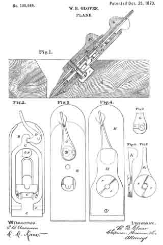
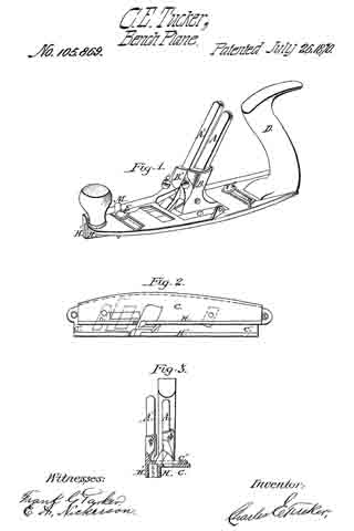
Be it known that we, JAMES RAYMOND BROWN and WILLIAM BROWN, subjects of the Kingdom of Great Britain, at present residing at Boston, in the county of Suffolk and State of Massachusetts, United States of America, have made an invention of a new and useful Carpenters’ Combination Plane; and do hereby declare the following to be a full, clear, and exact description thereof, due reference being had to the accompanying drawing making part of this specification, and in which —
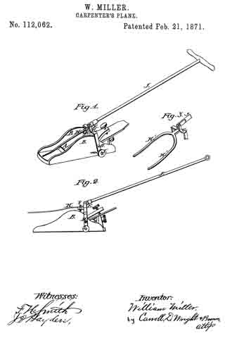
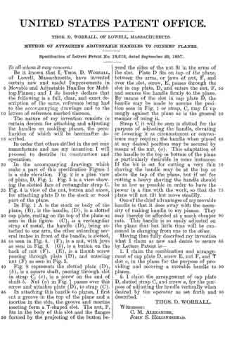
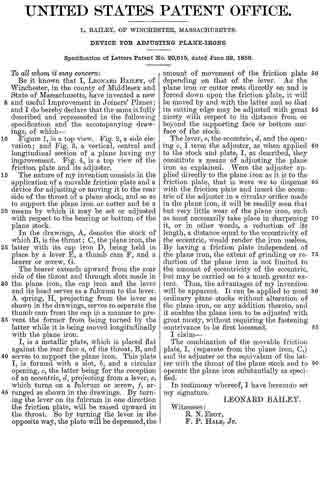
Figure 1 is a plan;
Figures 2 and 3 are side elevations;
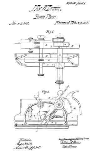
Figure 4, an end elevation; and
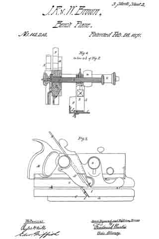
Figures 5 and 6, vertical and transverse sections of an implement embodying our improvements.
We have in the combination instrument herein expiained combined together elementary features susceptible of performing the functions for which several independent tools are now required, the advantages which we gain from such a combination being a considerable. economy in the use of space required to deposit tools of this nature, whether a carpenter’s chest in transportation or on sale in stores, or in use in a shop, and enabling a mechanic to obtain, at small comparative cost, and in a compact and efficient form, the substitutes for several classes of planes.
We have embraced in the combination about to be explained devices for rebating lumber for the manufacture of doors and for various other purposes; also devices which constitute a matching-plane for operating upon and preparing boards of various dimensions, and, finally, devices for plowing a cross-groove, the latter constituting one side of the matching-plane, and the whole operating as hereinafter explained.
The drawing accompanying this specification and illustrating our invention, represents, at A, a rebating-plane, substantially of ordinary construction, with the exception that the handle as ordinarily used is omitted, and in place thereof an upright arched standard, B, is employed, this standard being erected upon the base-plate C of the plane, and parallel to the longest axis of the same. This arched standard serves not only as a handle to operate the rebating-plane when the latter is used independent of the combination, but to some extent to serve as a support to the other members of such combination, and especially when the combined implement is not in use.
The arched standard is formed with a diagonal bar, D, sloping rearward, which serves as a bed for the “plane-iron,” which is shown at E as essentially of ordinary form, such iron being clamped to the bed by means of the bolt F, which passes through an orifice in the latter and also through along slot in the iron, the head of this bolt bearing upon the outer face of such iron, while its shank protrudes through the bed D, and immediately at the rear side of the latter is pivoted to the forward end of a cam-block, G, to the rear end of which a turn-button, H, is, in turn, pivoted, the pivot of the former being horizontal, while that of the latter is vertical.
The advance end of the block G is eccentric with its fulcrurn a, and is otherwise so arranged that upon forcing the block to a horizontal position, or there-abouts, the head of the bolt F is drawn forcibly upon the plane-iron, and serves to clamp the latter very securely to its bed, the block G being retained in this position by means of a series of saw-teeth, b b, &c., formed upon the rear limb of the arched standard B, and into one of the notches of which the turn-button H is forced.
Upon elevating the block G- its cam, c, will abut against a projecting stud, d, disposed below it and formed upon the rear side of the bed D, and will lift the bolt F and force its head from off the iron E, retaining it in such position while the iron is being removed from or applied to its place, and in this respect is a matter of great convenience to the user.
The bed-plate C of the plane A is formed with an upright lip or ledge, I, upon one side, which extends its whole length, this ledge serving as a “fence” to the matching-plane, to be hereinafter referred to, while to the under side of the said bed-plate C we apply a second fence or long right-angular plate, J, in such manner that while it is retained at all times parallel to the fence I and the longest plane of the bed-plate, it may be moved to and fro of the under side thereof in order to vary and determine the width of the rebate cut by the iron E, the addition of this fence J to the plane A converting it into a species of plane called “filister”-planes, or those in which the width of the rebate is governed at pleasure.
To enable this adjustment of the fence J to be easily and expeditiously effected, we pivot each end ot the same, by means of clamp-screws f f to the free end of a vibrating arm or carrier, g, which is applied to the upper part of the bed-plate C and pivoted to the same in immediate proximity to the ledge or fence I, the clamp-screws f f playing in segmental slots h h, cut through the plate C on a line concentric with the pivots of the arms g g.
By partially rotating the two arms g g the fence J is forced toward or away from the fence I, in a plane parallel thereto, while the screws f f, or their equivalents, serve to securely clamp such fence to the bed-plate of the plane.
The member of the combination instrument for performing the functions of plowing a cross-groove and for “matching stuff” is represented at k as composed of an upright wooden beam, L, to the rear end of which a handle, M, is applied in the ordinary manner of matching-planes.
The iron of the plane K is represented at N, and the sword of the same at O, being applied and disposed substantially as now and heretofore practiced in planes of this nature.
The “depth-gauge” of the beam L is represented in the drawing at P as applied to the under side thereof and in advance of its iron N, the relative position of this gauge or its distance from the beam being regulated by a screw, Q, which passes through the latter and is connected with it in at proper manner.
The gauge R determines the depth ofthe cut effected by the iron K, whether the latter be at work as a member of a filister-plane or in grooving the edge of a board or plank.
The scoring-knife or “spur,” which prepares the way for the knife N, is shown at R as inserted within a vertical orifice formed in the beam L, a long slot, S, being cut through the body of such spur, through which a cylindrical stud, T, passes, this stud, in turn, constituting part of a male screw, U, which is screwed into the body of the beam L, and so as to intercept such slot, the said slot T furthermore extending into a recess bored in the end of a second male screw, V, which is screwed into the beam and in axial alignment with the former, the conjoint function of the two screws U and V being to tightly clamp the spur R at any desired depth.
W in the annexed drawing represents a second “depth-gauge,” applied to the beam L in manner and relative position similar to that of the gauge P, the said gauge W serving to govern the depth of cut effected by the iron N, whether the same be employed for ordinary plowing or matching purposes, and also to govern the depth of an additional iron, which, under some circumstances, is brought into action in combination with the former, as hereinafter explained.
The member or plane K formed and equipped as last explained, is combined with the before-described rebating-plane A in a detachable manner, as follows:
A horizontal tubular support, X, is passed through the body of the beam L, and at the extreme rear upper part of the same, such support X projecting at right angles to the length of the beam and nesting in a concave bracket or shelf, Y, extending laterally from or making part of the arched standard B, hereinbefore mentioned as constituting part of the rebating-plane A, the tubular support or rod X being securely attached to the shelf Y by means of several partitubular or segmental plates k k, which partially circumscribe its periphery, and which, in conjunction with the shelf Y, inclose it, a male screw being cut about the circurnference of the conjoint sleeve thus produced, upon which screw a tubular and slightly-tapering nut, on, is screwed, and a chuck, n, acquired which tightly embraces the said support X.
While, then, the chuck n serves to firmly confine together or unite the two planes A and K, a means must be provided for adjusting the relative distance intervening between the two, as the fence I of the former performs a like function for the latter when plowing a groove in matching stuff. To accomplish this end I more the tubular support X to and fro upon the shelf Y as follows:
A tubular stud, p, is erected upon the bottom of such shelf and extends into the bore of the said support X, a long channel or slot, q, being out through the under side of the latter for reception of the stud and to permit the necessary lateral traverse of the support upon the shelf.
A long and attenuated male screw, r, is passed loosely through the bore of the support X and screws through the stud p, this screw being secured against endwise movement within the support by having a head upon each end, substantially as shown in fig. 5 of the accompanying drawing.
Revolutions of the screw p in either direction will induce traverse movements of the plane K toward or away from the plane A, the chuck n being; loosened to permit of this movement, and when the desired relative position is acquired, tightened, to insure a rigid and inseparable union of the two planes.
A second support, for aiding in the correct and stable connection of the two planes is shown at s in the drawing as a horizontal rod, projecting laterally from one side of the beam L and parallel to the tubular support X before mentioned, the rod s passing through a bearing, t, formed in the upper forward part of the arched standard B, and being conlined therein by a set-screw, as represented.
The last-remaining feature or member of the combination instrument we are describing is shown in the drawing at A’, and consists of a variable or adjustable plate, carrying a third knife or iron B’, to which brief allusion has herein before been made, the said plate serving as a sword to the plane K when the latter is engaged in matching stuff. The plate A is flat, and is applied flatwise to the outer or right side of the beam L, and is, in general form, a sector of a circular plate.
The apex of the sectoral plate A’ is swiveled to the beam L and plays upon or about a journal, w’, making part of the outer end of the rod s hereinbefore named as partially supporting the plane K, a suitable milled head or rosette, x, being affixed to the extreme outer end of said journal, by means of which the plate is clamped to the rod.
This rod s is formed with a small screw, y, which screws through the beam L; consequently rotations of said roll will compel endwise movements of the sword or plate A’ and its iron B’ toward or away from the beam L and its cutting-iron N.
The rear corner of the sword or plate A’ is pivoted and vibrates upon a lateral stud, a’, projecting from the side of the beam L, as shown in fig. 5 of the drawing. When the sword is not wanted for actual use, it is partially turned upon its pivot a’, which elevates it to a suflicient extent, and it is confined in either this or its working position by the milled head or nut x before referred to.
It sometimes becomes desirable to change the lateral position of the iron N of the matching-plane K, or to so force it inward that it shall not protrude beyond the outer face of the sword O.
The back of the said iron N is scored with two grooves, c’ d’, as shown in fig. 9 of the drawing, into one of which the adjacent edge of the sword O enters and confines it against lateral misplacement. The central groove, c’, is the one which insures the fixture of the iron in its normal working position, while the outer groove, d’, is so situated as to force the iron inward to such an extent that no part thereof shall protrude beyond the face of the sword.
By detaching the plane A from the plane K two independent planes are left, one a rebating-plane and the other a matching-plane. While united each one serves as a member of a combination instrument for performing certain work, which either can execute singly.
1. The combination of the two planes A and K and the sectoral plate or sword A’, under the arrangement and for operation essentially as herein set forth.
2. The combination, with the two planes A K, of the tubular support X, the screw r contained in the same, the shelf y, and the stud p, said. parts being arranged for joint operation, as herein shown and set forth.
3. The chuck n, constructed substantially as herein explained, in combination with the tubular support X, screw r, and shelf y, for the purposes stated.
4. The combination of the bar or rest D, the slot F, cam-block G, rack b, and iron E, the whole operating as herein explained.
5. The mode herein described of attaching the scoring-spur R to the beam L, the same consisting of the two screws U and V, formed and applied substantially as before set forth.
6. The combination, with the plane A, of the fence J, applied to the under side of the bed-plate, and the arms g, located on the upper side of said plate and hinged both to the plane and fence, for operation substantially as shown and set forth.
7. In combination with a matching-plane, an adjustable plate so made as to constitute a sword to such plane, and a carrier for the additional or second cutting-iron thereof, for purposes stated.
8. An adjustable plate, which combines a fence and iron-carriage so applied to the plane-beam as to be enabled to raise and lower the same from or into action, for purposes stated.
9. The combination of the planes A K, the beam L, the rod or screw S, and the adjustable sword or plate A, under the arrangement herein shown and set forth.
JAMES RAYMOND BROWN.
WILLIAM BROWN.
Witnesses:
FRED. CURTIS,
E. GRIFFITH.