No. 86,295 – Improvement In Bench-Planes (Philander S. Foster) (1869)

[paiddownloads id=”147″]86295


United States Patent Office.


PHILANDER S. FOSTER, OF RICHMOND, MAINE.

Letters Patent No. 86,295, dated January 26, 1869.
_________________

IMPROVEMENT IN BENCH-PLANES.

_________________

The Schedule referred to in these Letters Patent and making part of the same.

_________________

To all whom it may concern:

Be it known that I, PHILANDER S. FOSTER, of Richmond, in the county of Sagadahoc, and State of Maine, have invented a new and valuable Improvement in Bench-Planes; and I do hereby declare that the following is a full, clear, and exact description of the construction and operation of the same, reference being had to the annexed drawings, making a part of this specification, and to the letters and figures of reference marked thereon.

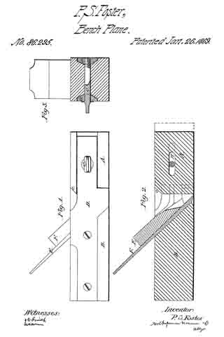
Figure 1, of the drawings, is a side view of my bench-plane;
Figure 2 is a longitudinal section; and
Figure 3 is a cross-section of the same.

My invention relates to that class of bench-planes constructed partly of wood and partly of metal; and It consists in providing a remedy against the difficulty commonly called choking, by means that are more permanent and efficient than have heretofore been devised.

By my device, also, a wider bit may be used, and consequently a wider shaving be cut, than by the ordinary bench-planes.

The letter A, of the drawings, represents the removable and adjustable wooden front of the plane, and the letter B is the wooden rear thereof.

The part A is constructed with a slot in its middle, running lengthwise, as shown on fig. 2, adapted to hold and operate with the thumb-screw C. This slot is marked H on the drawings.

The letters D are metallic plates, adjusted respectively on each side of the wooden parts of the plane, in the manner shown on figs. 1 and 3.

That portion of these metallic side plates respectively which is adjusted forward of the bit and throat, is constructed in a bevelled form, as shown on fig. 3, and is adapted to corresponding grooves, out in the sides of the part A, in which grooves it is held securely and firmly by the thumb-screw C, in conjunction with its bevelled form so resting in its grooves.

The part A is cut off square at its rear end, leaving a small bevel at the point c, upon which the hammer may be used.

I sometimes also arrange metallic boxings in the grooves of the part A, adjusted to the plates D. These boxings will save the wear of the wood, and when properly oiled, will aid in the adjustment of said part to the bit of the plane.

The thumb-screw G passes through both plates D and the slot H, and serves as a means of tightening, loosening, and fastening the part A, at the will of the operator.

The letter E is the bit, and letter F is the wedge of the plane. These are adjusted in diagonal slots, formed in the inner sides of the plates D respectively, in the manner shown on fig. 2.

The fact that the bit and wedge are adjusted in plates of metal, instead of the wooden throat of the plane, as is usual, justifies the manufacturer in adapting a bit to the plane, that shall be wider, and consequently shall out a wider shaving than is prudent in planes wherein the bit is adjusted in wood only.

It will readily be perceived that by the upright formation of the rear end of part A, the plane is provided with a large open throat, which greatly lessens the danger of choking, and that in case such an event occurs, the chips in the throat may be easily loosened and removed, by moving the part A forward. This movement is effected by unscrewing the thumb-screw C, and striking a gentle blow with a hammer on the bevel c.

What I claim as my invention, and desire to secure by Letters Patent, is —

A bench-plane, having bevelled metallic side plates D, wooden sections A and B, slot H, and thumb-screw C, when the same are constructed and arranged as specified.

In testimony that I claim the above, I have hereunto subscribed my name, in the presence of two witnesses.

PHILANDER S. FOSTER.

Witnesses :
WM. S. HAGAR,
WM. H. STUART.

No. 50,530 – Improvement In Bench Planes (Lyman C. Bliss) (1865)

[paiddownloads id=”108″]50530


UNITED STATES PATENT OFFICE.

_________________

LYMAN C. BLISS, OF RICHMOND, INDIANA, ASSIGNOR. TO LYMAN C. BLISS AND JOHN GRIFFITH.

IMPROVEMENT IN BENCH-PLANES.

_________________

Specification forming part of Letters Patent No. 50,530, dated October 17, 1865.

_________________

To all whom it may concern:

Be it known that I, LYMAN C. BLISS, of Richmond, in the county of Wayne and State of Indiana,have made new and useful Improvements in Bench-Planes; and I do hereby declare the following to be a full, clear, and exact description of the nature, construction, and operation of the same, sufficient to enable one skilled in the art to which it appertains to construct and use the same, reference being had to the accompanying drawings, which are made part of this specification, and in which —

Figure 1 is a View of the under side or face of the plane. Fig. 2 is a longitudinal vertical section on the line x x, Figs. 1 and 3. Fig. 3 is a transverse vertical section on the line y y, Figs. 1 and 2.

The same letters refer to corresponding parts in the different figures.

The invention consists in the adaptation to and arrangement in the tool of the jointer and slat-cutting plane.

A is the stock ofthe plane; and B,a strip which is fastened to the face of the plane, acting as a guide and separating the bits., The side C of the plane is occupied by the jointing-bit D, of ordinary construction, and the other side of the plane is faced with plates E and F, the former of which passes from the hind end of the plane to the back edge of the bit G, while the other, starting from the forward end of the plane, is partially overlapped by the oblique edge of the plane-bit G. The bit G is secured by means of a bolt, H, which passes through the slot in the rear edge of the bit and also through an orifice in the plate F, which on its rear edge is divided. The portion f of the plate, or that immediately over the longitudinal channel I in the face of the plane-stock, is cut diagonally, so as to present a yielding edge parallel with the cutting-edge of the bit, which overlaps it.

The operation is as follows: The jointing-bit D being first brought into action, the board from which the strip, splint, or slat is to be cut is straightened, when the plane is shifted so as to bring the other side into action, the sliver cut by the bit G pressing back the tongue f of the plate F, and passing out by the way of the channel I, to be discharged at the rear end ofthe plane. The splint or slat being separated from the edge of the board by the draw-cut of the bit G, leaves the said splint smoother and without cracks.

Having described my invention, what I claim therein as new, and desire to secure by Letters Patent, is —

As an article of manufacture, a bench-plane constructed, as described, with a jointing-bit and a draw-cut splint-cutting bit on the opposite sides of the dividing-strip on the face of the plane.

LYMAN O. BLISS.

Witnesses :
JOHN FINLEY,
THOS. A. DUGDALE.

No. 50,947 – Improvement In Splint Planes (Harrison Ogborn) (1865)

[paiddownloads id=”109″]13957


UNITED STATES PATENT OFFICE.

_________________

HARRISON OGBORN, OF RICHMOND, INDIANA.

IMPROVEMENT IN SPLINT-PLANES.

_________________

Specification forming part of Letters Patent No. 50,947, dated November 14, 1865.

_________________

To all whom it may concern:

Be it known that I, HARRISON OGBORN, of Richmond, in the county of Wayne and State of Indiana, have invented certain new and useful Improvements in Planes for Cutting Blind-Slats, Splints for Baskets, and other similar work; and I do hereby declare that the following is a full, clear, and exact description of the construction and operation of the same, reference being had to the annexed drawings, made a part of this specidcation, and the letters of reference thereon, the same letters referring to identical parts.

Figure 1 is a side view of the plane when arranged for use as a jack-plane, showing the bottom of the plane used for cutting slats, &c.
Fig. 2 is a longitudinal vertical section of the plane through the line y y, Fig. 4. Fig. 3 is a like section through the line x x, Fig. 4. Fig. 4 is a transverse section of the stock. Fig. 5 is a view of the knife employed for splitting the slats or splints. Fig. 6 is a view of a knife for splitting the slats with beveled edges. Fig. 7 shows the adjustable plate for determining the cut and removing splinters that wedge in the plane. Fig. 8 is a sectional view of the knife or bit used on the splint-plane. Fig. 9 is a top view of the same.

The stock of the plane A is arranged for two bits, and having two faces. One of these is an ordinary jack-plane, as shown in Figs. 1 and 2.

The handle B is adjustable, and may be made to stand perpendicularly to either of the plane-faces. It turns upon a rod, M, and, swinging in a notched recess in the corner of the stock, is held perpendicularly to either face by an ordinary window-catch, of which there are two shown, Figs. 2 and 3, G G’.

On the bottom of the face of the splint-plane are shown two adjustable guides, one square, the other beveled. One of these, according to the character of the work, is used on the left-hand side of the plane, held in place by screws with oblong heads working in slots in the ends of the guides, as shown in Fig. 1.

D is the knife or bit ofthe splint-plane, held in place by the same kind of screws working in slots, so as to allow the adjustment of the knife by the aid of the set-screws N N.

E shows the bit of the jack-plane, of ordinary construction, and arranged in the usual manner.

K is an adjustable plate, held by similar screws on the face, allowing its adjustment to the knife as they are worn away in use, to which is attached the set-screw passing through the stock and working in a collar on the upper surface of the plane. This arrangement makes it easy to withdraw the plate in case a splinter should wedge in the space between the plate and knife.

The knives H I, one straight, the other bent for cutting beveled edges, work as shown in Figs. 3 and 4. The knives are held in place by the wedge L, and the points protrude through narrow slots in the plate K. (Shown in Fig. 1.) The bent knife its the beveled point of the wedge L. When the straight knife is used the wedge goes on the right of it, but on the left side of the bent knife. There are one or more of these knives used, according to the number of slats intended to be cut from the board. The bent knife is used with the beveled guide.

In operating with this plane, the boards, being dressed, are cut into narrow strips of the proper width on their edges by the knife H, or so that the slats shall have beveled edges, by the knife I. The splints are cut by the knife or bit D passing between the plate K and the bit D. Rising over D, they are bent in a contrary direction, and passing out under the lower surface of the plane they are flattened and delivered free from curves or tendency to twist.

Having thus fully explained the character and operation of my improvements, what I claim as my invention, and seek to secure by Letters Patent, is —

1. The arrangement, in a splint-plane, of the plate K, bit D, and one or more splitting-knives, and guide C, all constructed and combined substantially as and for the purpose set forth.

2. The arrangement, in a splint-plane, of the piate K, bit D, beveled guide C and one or more bent knives, I, all constructed and combined substantially as and for the purposes set forth.

3. The combination of the plane-stock A and adjustable handle B, so constructed with the rod M and springs G and G’ as to be capable of being arranged perpendicularly to the two faces of the plane, substantially as described. In testimony whereof I have signed my name to this specifcation in the presence of two subscribing witnesses.

HARRISON OGBORN

Witnesses:
R. MASON, BEN FIELD.

No. 51,153 – Improvement In Splint Planes (James Dempsey) (1865)

[paiddownloads id=”110″]51153


UNITED STATES PATENT OFFICE.

_________________

JAMES DEMPSEY, OF RICHMOND, INDIANA.

IMPROVEMENT IN SPLINT-PLANES.

_________________

Specification forming part of Letters Patent No. 51,153, dated November 28, 1865.

_________________

To all whom it may concern:

Be it known that I, JAMES DEMPSEY, of Richmond, in the county of Wayne and State of Indiana, have invented certain new and useful Improvements in Planes for Cutting Slats for Window-Shades or other Thin Splints of Wood.

The object of my invention is to construct a splint-plane that shall be as readily adjustable as the ordinary hand-plane, and have such a channel for the splint when out as that it shall not be broken by being thrown abruptly upward over the knife. In other planes either the splint is liable to be broken or the knife placed horizontally is ditiicult of adjustment. Another object is to provide that the splint when cut shall be perfectly smooth and fit for use as it comes from the plane. Both of these objects are, I believe, accomplished by my im-provements.

To enable others skilled in the art to make and use my invention, I will describe its construction and operation, reference being had to the annexed drawings, making a part of this specification, and the lettering thereon.

In the different plans the same letters refer to identical parts.

Figure 1 is an elevation showing the half of the plane when divided into two parts, on the line x x, Fig. 3, where the plane as constructed is divided. Fig. 2 is a longitudinal section on the line x x, Fig. 3. Fig. 3 is a transverse section upon the line y y, Fig. 4. Fig. 4 is a plan of the plane, showing the bottom part, the guide being represented as cut away in part. Fig. 5 is a plan showing the construction of the bit. Fig. 6 is a plan showing the construction of the spring in the bottom of the plane.

The stock is made in two parts, A and B, of wood, joined by the dowel-pins L L and by screws.

C is the bit, of which about two inches of the lower end is nearly horizontal, but depressed at the point sutliciently to give the cutting-edge the requisite draft into the wood. It is bent at N, rising and passing transversely through the stock. It is adjusted by the set-screw H, and held firmly in place by the wedge M and clamps E E. These clamps catch upon the bit below and hold it firmly by stress of the nuts E’ E’ upon their upper ends. This bit is constructed with the rectangular slot G, which opens from the angle and extends upward about three inches, and having a width of about seven-eighths (7/8) of an inch. Over this slot the spring G is placed, bent upward and having the upper extremity, near O, turned slightly down, so as to hold firmly to the splint as it passes, and yet guide it through the slot at O. Upon the bottom of the plane, attached by a set-screw working in the slot F, is the spring D, the tongue extending above the bit and forming a guide for the splints as cut. On the bottom of the side B of the stock is fastened a guide, P, made adjustable by the set-screws and slots K.

On the under side ofthe wedge M, at its lower extremity, is cut a groove, of the width of the slot in the bit C, and terminating a little above the point ofthe spring G. Through this groove passes the splint.

In operating with the plane the guide p is set at one-half the width of the splint to be cut from the line x x. The bit C and spring D being adjusted by the set-screws I and H to cut splints of the required thickness, the bit C is held firmly in place by the wedge M and clamps E. The splint, being cut by the sharp point of the bit, rises above it, passing under the tongue of the spring upward through the groove in the under side of the wedge M, over the spring G. It passes through the bit C at O, and is carried through the stock in the groove D, passing out behind the plane unbroken and highly polished by the combined action of the cutter-bit and spring.

Having fully explained my mode of constructing and operating splint-planes, what I claim as my invention, and seek to secure by Letters Patent, is —

1. Constructing the bit C of a splint-plane with the slot and spring, substantially as described.

2. The arrangement of the spring D, clamps E, wedge M, stock A B, with the bit C, all of them constructed and combined substantially as and for the purpose described.

In testimony whereof I have signed my name to this specification in the presence of two subscribing witnesses.

JAMES DEMPSEY.

Witnesses:
R. MASON,
JOHN S. HOLLINGSHEAD.