No. 837,978 – Scraping-Tool (Justus A. Traut) (1906)

[paiddownloads id=”636″]837978


UNITED STATES PATENT OFFICE.

_________________

JUSTUS A. TRAUT, OF NEW BRITAIN, CONNECTICUT, ASSIGNOR TO STANLEY RULE &
LEVEL COMPANY, OF NEW BRITAIN, CONNECTICUT, A CORPORATION OF CONNECTICUT.

SCRAPING-TOOL.

_________________

837,978. Specification of Letters Patent. Patented Dec. 11, 1906.
Application filed May 26, 1906. Serial No. 318,811.

_________________

To all whom it may concern:

Be it known that I, JUSTUS A. TRAUT, a citizen of the United States, residing at New Britain, Hartford county, Connecticut, have invented certain new and useful Improvements in Scraping-Tools, of which the following is a full, cllear, and exact description.

My invention relates to improvements in woodworking-tools; and it consists in an improved scraper, the construction of which is such that it may be used, if desired, with an ordinary plane, merely substituting the same for the usual plane-iron. In this connection the device is capable of all of the adjustments to which the usual plane-iron is adapted and may be employed with an unusual degree of success.

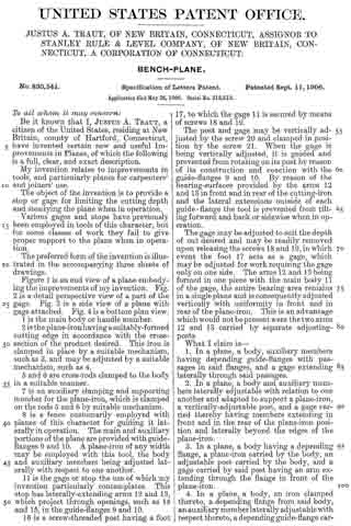
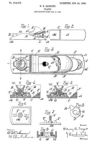
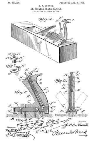
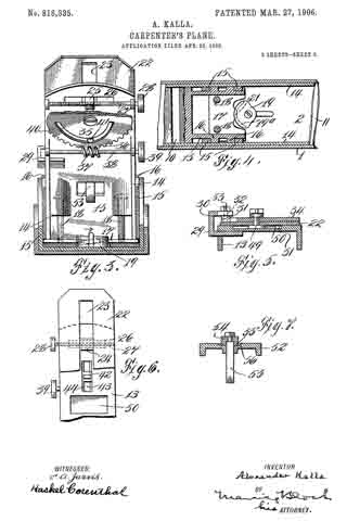
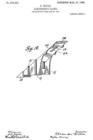
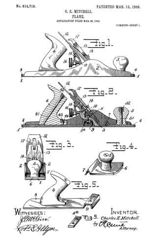
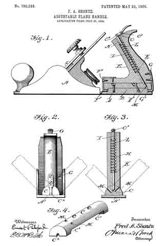
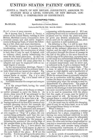
In the accompanying drawings, Figure 1 is a longitudinal section of an ordinary plane-body fitted with my improved scraper. Fig. 2 is a perspective view of the scraper and scraper frame or carrier. Fig. 3 is a plan view of the same. Fig. 4. is a detail view of a clamping member.

I will first describe the scraper and scraper-carrier.

A is the scraper-blade, having the usual sharpened edge.

B B’ are two arms of the frame or scraper-carrier arranged to carry the blade A. As shown, these arms B B’ are arranged in the form of a wedge or a V — that is, the outer bearing-surfaces of the same form a V. The plane-iron A is clamped against the outer bearing-surface of the arm B by means of any suitabie clamping device — for example, the member C, carrying the clamping-screw C’. The arm B’ is so constructed and arranged that it may be readily applied to the plane-iron support or “frog” of a plane, the connection being preferably such that the various adjusting devices commonly found on planes will be available for the purpose of adjusting the position of the cutting edge of the scraper-blade in the throat of the plane. In the drawings, Fig. 1, I have shown the scraper-frame as it would appear in place on an ordinary plane. In this view, D indicates the main body of the plane. E E’ are the handles. F is the usual frog on the plane-iron support. G is the usual clamping- plate cooperating with the screw-post J. H I are adjusting-levers such as commonly employed in planes and by which the plane-iron may be given any desired adjustment. These levers need not be explained in detail, since their operation is well understood.

On referring to Fig. 1 it will be seen that the scraper-frame is clamped to the frog precisely as the ordinary plane-iron is clamped thereon, and the edge of the scraper-blade A will project through the throat or passage in the sole of the plane in the same manner as will the edge of the plane-iron, excepting that it will stand at a substantially different angle. The arm B of the scraper-frame is cut back or recessed transversely near its lower end, as indicated at K, to give a clearance back of the cutting edge of the scraper-blade. This is done to permit the cutting edge of the scraper to yield slightly and is productive of the most effective results in operation. While the scraper-frame is primarily adapted for use in connection with the plane, nevertheless the frame or carrier will itself afford a convenient grip when the scraper is used independently of a plane-body. The angle of the bearing-surfaces of the arms B B’ (indicated in the drawings) is that best adapted for the most successful results when the scraper is to be used in connection with the plane; but this angle, of course, may be varied to some extent at will. In the arm B’ of the scraper-frame a central longitudinal passage B2 adords clearance for the post J.

L is the usual cam by which the clamping-plate G may be set down hard, so as to hold the scraper-frame firmly on its seat.

What I claim is —

1. As an article of manufacture, a scraper attachment for a plane, comprising a body having two arms inclined relatively to each other, a scraper-blade, means for adjustably securing the scraper-blade to one of said arms, the other arm having a longitudinal recess and a transverse recess above said longitudinal recess, said recesses being adapted to accommodate mechanism of a plane for effecting lateral and vertical adjustment respectively.

2. As an article of manufacture, a scraper attachment for a plane comprising, a body having two arms arranged at an angle relatively to each other and furnishing two bearing-surfaces, one for contact with the plane-support, the other for the reception of a scraper-blade, a scraper-blade, means for adjustably securing the same to the said bearing-face, said bearing-face at and near the meeting angle of the two arms being recessed to afford clearance for the blade adjacent to its cutting edge.

JUSTUS A. TRAUT.

Witnesses:
H. S. WALTER,
L. E. CLEMONS.

No. 830,541 – Bench-Plane (Justus A. Traut) (1906)

[paiddownloads id=”635″]830541


UNITED STATES PATENT OFFICE.

_________________

JUSTUS A. TRAUT, OF NEW BRITAIN, CONNECTICUT, ASSIGNOR TO STANLEY RULE &
LEVEL COMPANY, OF NEW BRITAIN, CONNECTICUT, A CORPORATION OF CONNECTICUT.

BENCH-PLANE.

_________________

830,541. Specification of Letters Patent. Patented Sept. 11, 1906.
Application filed May 26, 1906. Serial No. 318,812.

_________________

To all whom it may concern:

Be it known that I, JUSTUS A. TRAUT, a citizen of the United States, residing at New Britain, county of Hartford, Connecticut, have invented certain new and useful Improvements in Planes, of which the following is a full, clear, and exact description.

My invention relates to improvements in tools, and particularly planes for carpenters’ and joiners’ use.

The object of the invention is to provide a stop or gage for limiting the cutting depth and steadying the plane when in operation.

Various gages and stops have previously been employed in tools of this character, but for some classes of work they fail to give proper support to the plane when in operation.

The preferred form of the invention is illustrated in the accompanying three sheets of drawings.

Figure 1 is an end view of a plane embodying the improvements of my invention. Fig. 2 is a detail perspective view of a part of the gage. Fig. 3 is a side view of a plane with gage attached. Fig. 4 is a bottom plan view.

1 is the main body or handle member.

2 is the plane-iron having a suitably-formed cutting edge in accordance with the cross-section of the product desired. This iron is clamped in place by a suitable mechanism, such as 3, and may be adjusted by a suitable mechanism, such as 4.

5 and 6 are cross-rods clamped to the body in a suitable manner.

7 is an auxiliary clamping and supporting member for the plane-iron, which is clamped on the rods 5 and 6 by suitable mechanism.

8 is a fence customarily employed with planes of this character for guiding it laterally in operation. The main and auxiliary portions of the plane are provided with guide-flanges 9 and 10. A plane-iron of any width may be employed with this tool, the body and auxiliary members being adjusted laterally with respect to one another.

11 is the gage or stop the use of which my invention particularly contemplates. This stop has laterally-extending arms 12 and 13, which project through openings, such as 14 and 15, in the guide-flanges 9 and 10.

16 is a screw-threaded post having a foot 17, to which the gage 11 is secured by means of screws 18 and 19.

The post and gage may be vertically adjusted by the screw 20 and clamped in position by the screw 21. When the gage is being vertically adjusted, it is guided and prevented from rotating on its post by reason of its construction and coaction with the guide-flanges 9 and 10. By reason of the bearing-surfaces provided by the arms 12 and 13 in front and in rear ofthe cutting-iron and the lateral extensions outside of each guide-flange the tool is prevented from tilting forward and back or sidewise when in operation.

The gage may be adjusted to suit the depth of cut desired and may be readily removed upon releasing the screws 18 and 19, in which event the foot 17 acts as a gage, which maybe adjusted for work requiring the gage only on one side. The arms 12 and 13 being formed in one piece with the main body 11 of the gage, the entire bearing area remains in a single plane and is consequently adjusted vertically with uniformity in front and in rear of the plane-iron. This is an advantage which would not be present were the two arms 12 and 13 carried by separate adjusting-posts.

What I claim is —

1. In a plane, a body, auxiliary members having depending guide-flanges with passages in said flanges, and a gage extending laterally through said passages.

2. In a plane, a body and auxiliary members laterally adjustable with relation to one another and adapted to support a plane-iron, a vertically-adjustable post, and a gage carried thereby having members extending in front and in the rear of the plane-iron position and laterally beyond the edges of the plane-iron.

3. In a plane, a body having a depending flange, a plane-iron carried by the body, an adjustable post carried by the body, and a gage carried by said post having an arm extending through the flange in front of the plane-iron.

4. In a plane, a body, an iron clamped thereto, a depending iiange from said body, an auxiliary member laterally adjust able with respect thereto, a depending guide-flange carried by said auxiliary member, and a vertically-adjustable gage in the rear of the plane-iron position extending through said flanges.

5. In a plane, main and auxiliary sections, depending flanges carried thereby, a plane-iron held between said sections, a vertically-adjustable post having a foot, and a gage removably secured to said foot and having an arm extending through said flanges.

6. In a plane, main and auxiliary sections, depending flanges carried thereby, a plane-iron held between said sections, a vertically-adjustable post having a foot, and a gage removably secured to said foot and having arms extending through said flanges in front and in the rear of the plane-iron.

7. As an article of manufacture, a plane-gage attachment comprising a body, means of attachment to a plane, and laterally-extending arms carried by the body spaced apart from each other and lying in the same plane with the body.

JUSTUS A. TRAUT.

Witnesses:
W. J. WORAM,
H. S. WALTER.

No. 827,473 – Plane (Lewis Dorus Smith) (1906)

[paiddownloads id=”634″]827473


UNITED STATES PATENT OFFICE.

_________________

LEWIS DORUS SMITH, OF PORT HURON, MICHIGAN, ASSIGNOR TO
STANLEY RULE AND LEVEL COMPANY, A CORPORATION OF CONNECTICUT.

PLANE.

_________________

827,473. Specification of Letters Patent. Patented July 31, 1906.
Application filed March 15, 1904. Serial No. 198,203.

_________________

To all whom it may concern:

Be it known that I, LEWIS DORUS SMITH, a citizen of the United States, residing at Port Huron, county of St. Clair, State of Michigan, have invented certain new and useful Improvements in Planes, of which the following is a full, clear, and exact description.

My invention relates to improvements in planes, and particularly to a plane which is adapted to carry any one of a large variety of cutters or plane-irons. A plane of the same general class is shown in the United States Letters Patent No. 532,84.

The object of my invention is to construct a plane which shall be efficient and readily interchangeable and adjustable for different classes of work. I have also sought to make the construction as simple as possible, so that the adjustments and interchanges may be effected easily, and the cost of manufacture may be reasonable. I have also sought to construct a plane which shall be useful in connection with classes of work hitherto impossible to planes of this type.

A plane embodying my invention is shown in the accompanying single sheet of drawings. Two parts of the plane are adjustable laterally with relation to one another and adapted to carry a plane-iron. Between the two adjustable portions is located a gage for limiting the cutting depth of the iron. This gage is adjustable vertically and laterally and is readily removable. When desired , an auxiliary guide may be employed.

Figure 1 is a side elevation of a plane embodying the improvements of my invention, a portion of an auxiliary guide being shown dotted. Fig. 2 is a front elevation of a plane embodying the improvements of my invention shown as in operation. Fig. 3 is a detail perspective view of the center gage and attachments. Fig. 4 is a bottom view of the complete plane. Fig. 5 is a vertical sectional view on the plane of the gage-support.

1 is the main stock portion having a handle 2 and a guide-blade 3.

4 is a plane-iron, having a suitable cutting edge — as, for instance, a “hollow.”

5 is a screw of suitable construction for clamping the plane-iron to the main stock 1.

6 is an adjusting screw for varying the cutting depth.

7 is a gage carried at the outer side of the main stock and adjustable in a suitable manner by means of the screw 8.

9 is a guide-rod which extends laterally from the main stock 1 and may be secured thereto by means of the screw 10. 11 is a similar guide-rod at the rear, which may be attached to the main stock by means of the screw 12.

13 is what may be conveniently termed a “sliding section,” having the guide-blades 14 and 15 corresponding to the guide-blades 3 and 30 of the main stock. This section 13 is adjustable laterally on the guide-rods 9 and 11 to and from the main stock 1. 16 and 17 are thumb-screws for holding it in the desired position. In the instance herein shown the distance from the outer surface of the guide-blade 3 to the outer surface of the guide-blade 14 is approximately equal to the width of the cutter or plane-iron 4.

18 indicates a section of a molding, a portion of which has just been formed by the cutter 4. It will be obvious to one acquainted with this art that cutters of many different forms may be employed with a tool of this character to shape a molding, as desired.

19 is a gage for steadying the plane and limiting the cutting depth of the plane-iron 4. 20 is a post which is vertically adjustable in a recess in the outer surface of the sliding section 13. 21 is a thumb-screw for securing it in place. 22 is a horizontal member for connecting the adjustable post 20 and the gage 19. In this instance the horizontal bar is carried by the post 20. 23 is a thumb-screw which clamps the gage to the horizontal cross-bar 22. The gage preferably has an enlarged portion 24 at the top, which is open at the rear, so that the gage may be removed by simply loosening the screw 23 and slipping the gage forward. The gage in this way may be removed without being obstructed by the guide-rod 9. By this construction the center gage 19 may be adjusted vertically and also laterally, so as to provide for different widths and conformations of cutters.

25 is a longitudinal guide or fence which may be carried by the longitudinal guide-rods 9 and 11 and adjustable laterally thereon. 26 is a handle for convenience in operation. Such a guide or fence is not necessary in all kinds of work; but in forming a molding, as herein illustrated, it is advantageous.

What I claim is —

1. In a plane, the combination of a handle member, a sliding section member adjustable relatively thereto, a laterally-projecting lug carried by one of said members and having a vertical passage-way, a post passing through and vertically adjustable in said passage-way, a laterally-extending thumb-screw passing through said lug for coacting with said post, and a center gage located between said members and means for supporting said gage from said vertical post.

2. A plane-gage attachment of the character described comprising the combination of two substantially parallel rods, a shoe member carried by one of said rods, a connecting member having one endf fixedly secured to one rod and an adjustable clamping means carried by the other rod for engagement with said member and having an open horizontal slot, substantially as described for the purpose specified.

3. A plane-gage attachment of the character described, and for the purpose specified, comprising the combination of two substantially parallel rods spaced apart from each other, a shoe member carried by one of said rods, a laterally-projecting connecting member having one end fixedly secured to one of said rods, the other rod being laterally adjustable upon the connecting member of the first rod, and means for clamping the second rod upon said connecting member.

Signed at Port Huron, Michigan, this 5th day of March, 1904.

LEWIS DORUS SMITH.

Witnesses:
S. V. JONES,
LEWIS ATKINS.

No. 824,954 – Plane (John H. Shaw) (1906)

[paiddownloads id=”633″]824954


UNITED STATES PATENT OFFICE.

_________________

JOHN H. SHAW, OF NEW HAVEN, CONNECTICUT, ASSIGNOR TO SARGENT AND COMPANY,
OF NEW HAVEN, CONNECTICUT, A CORPORATION OF CONNECTICUT.

PLANE.

_________________

824,954. Specification of Letters Patent. Patented July 3, 1906.
Application filed April 17, 1903. Serial No. 153,092.

_________________

To all whom it may concern:

Be it known that I, JOHN H. SHAW, of the city and county of New Haven, State of Connecticut, have invented new and useful Improvements in Planes, of which the following is a full, clear, and exact description when taken in connection with the accompanying drawings, which form a part thereof, and in which —

Figure 1 represents a central vertical section, the ends being shown in elevation, of a plane embodying my invention; Fig. 2, a plan view of the bed of the plane; Fig. 3, a vertical transverse section on lines 3 3 of Fig. 1; Fig. 4, a longitudinal vertical section on lines 4 4 of Fig. 3 of a portion of the plane; Fig. 5, a similar view, the bit being shown in a different adjustment; and Fig. 6 is a perspective view of the support E.

In all figures similar letters of reference represent like parts.

This invention relates to planes, and has for its object the production of a plane in which the frog may be adjusted longitudinally and clamped in place after the bit is clamped to the frog.

in the proper adjustment of the bit of a plane it is necessary to move the bit longitudinally on the frog, so that the cutting edge will project more or less through the throat of the frame according to the depth of the cut desired. When properly adjusted, it is necessary in order that the bit may be held firmly in place that its cutting end should rest against the rear of the throat and against the frog. Owing to the variations in the angle to which the bit is ground, the adjustment of the bit longitudinally on the frog may affect its position in the throat and against the frog. It is an important desideraturn, therefore, in order to prevent what is known as “chattering,” which occurs when the lower end of the bit is not held firmly against the throat and frog, that the frog may be adjusted on the frame after the bit is adjusted longitudinally on it, because were it necessary to remove the bit in order to adjust the frog a number of attempts might be required to establish the exact relation between the frog and throat and beveled end of the bit.

To this end my invention resides in the production of a novel construction by which the adjustment of the frog may be made from the rear after the bit is secured to the front face of the frog, as set forth and claimed hereinafter, together with other minor improvements.

Referring to the drawings for a more particular description, the parts designated by the letter A represent the frame or stock of the plane, and a the throat thereof, which extends transversely across the bottom.

B is a raised portion near the middle of the frame having screw-holes b and a vertical flange b’ at right angles to the plane, provided with a substantially semicircular groove b2.

C’ represents the bit or plane iron, to which is secured b the screw c the cap-iron D. The forward end d of the cap-iron D is bowed outward in well-known manner.

E is a frog or support for the bit adapted to rest on the raised portion B of the frame A and having a depending portion e, adapted to rest on the frame A immediately in the rear of the throat a.

F is a screw projecting from the front of the support E, the head of which is adapted to engage and hold in place the clamping-cap G. The forward end of the clamping-cap G bears on the bowed portion d of the cap-iron D, and pivoted to the rear end of the clamping-cap is a cam-clamp H, adapted to bear on a spring-plate it to lock the cap in place between the engaging head of the screw F and the cap-iron D.

I designates a set-screw secured to said support and on which is mounted a nut J, having an annular groove j, engaged by the forked end k of a bell-crank lever K, plivoted at k’ to the support, and having its other end k2 engage the cap-iron D in well-known manner. By means of the nut J and lever K the cap-iron D and the bit C, secured thereto, are adjusted longitudinally on the forward inclined face of the support E.

L is a lever pivoted to the support at l, adapted to engage the screw c, connecting the bit C and cap-iron D. By means of the lever L the bit may be adjusted transversely in well-known manner.

M is an adjusting-screw adapted to be screwed into the rear of the support and having on its head an annular groove m, adapted to be engaged by a flange b’ on the frame of the plane. The support E has lateral projecting portions e’ upon its respective sides and preferably extending to the rear of the body portion thereof, and e” designates upright arms on said projecting portions connecting with the body portion.

O designates one or more clamping-screws adapted to extend through longitudinal slots P in the projecting portions of the support and engage in internally-threaded screw-holes b in the frame.

By this construction it is possible to adjust and clamp the support in place after the bit is properly mounted on the support, for after the bit is so mounted the clamping-screws O may be loosened and the support moved forward or backward by the adjusting-screw M.

Having now described my invention, what I claim, and desire to secure by Letters Patent, is —

1. In a plane, the combination with a frame, of a bit, a throat in said frame throihgh which said bit may project, a longitudinally-adjustable frog or support carrying the bit-adjusting means, a part carried by the support and projecting rearwardly of the bit-adjusting means, an clamping means for retaining the support in adjusted position, said clamping means being arranged to engage said projecting part of the support at a spaced distance from the body part thereof, whereby it is accessible when the bit is mounted on the support.

2. In a plane, the combination with a frame, of a bit, a throat in said frame through which said bit may project, a bodily-adjusting means, and means for clamping said support in its adjusted position carried by a rearwardly-projecting portion of the frog and accessible when the bit is mounted on said support.

3. In a plane, the combination with a frame, of a bit, a throat in said frame through which the bit may project, a movable support on said frame to the rear of said throat and carrying the bit-adjusting means, an adjusting-screw for adjusting said support longitudinally of said frame from the rear of said support, and a clamping screw or screws adapted to hold said support in its adjusted position, said screw or screws being carried by a rearwardly-projecting part of the support and accessible when said bit is in place on said support.

4. In a plane, the combination with a frame having a portion substanially parallel to the bottom thereof, of a bit, a throat in said plane through which the bit may project, a support carrying the bit-adjusting means on said frame capable of moving longitudinally on said parallel portion of said frame, a slot in a rearwardly-projecting portion of said support, and a clamping-screw passing through said slot into said frame to hold the support from movement on said frame, whereby said clamping-screw is accessible for mampulation while said bit is in place on said support.

In witness whereof I have hereunto set my hand on the 28th day of February, 1903.

JOHN H. SHAW.

Witnesses:
LE ROY J. KIRKHAM,
ALICE A. WILSON.

No. 820,639 – Plane (Andrew N. Gabrielson) (1906)

[paiddownloads id=”632″]820639


UNITED STATES PATENT OFFICE.

_________________

ANDREW N. GABRIELSON, OF MOUNT IRON , MINNESOTA.

PLANE.

_________________

820,639. Specification of Letters Patent. Patented May 15, 1906.
Application filed December 18, 1905. Serial No. 292,203.

_________________

To all whom it may concern:

Be it known that I, ANDREW N. GABRIELSON, a citizen of the United States, residing at Mount Iron, in the county of St. Louis, State of Minnesota, have invented certain new and useful Improvements in Planes; and I do hereby declare the following to be a full, clear, and exact description of the invention, such as will enable others skilled in the art to which it appertains to make and use the same.

This invention relates to planes, and more particularly to hand-planes, and has for its object to provide a plane which may be used either as a jack-plane or a smoothing-plane and which will be provided with guides arranged for movement into and out of position to lie against the working face of the board to insure even planing of the edges thereof.

Other objects and advantages will be apparent from the following description.

In the drawings forrning a portion of this specification, and in which like numerals of reference indicate similar parts in both views, Figure 1 is a side elevation of the present plane with the guides in the rabbets and showing them in lowered position in dotted lines. Fig. 2 is a transverse section on line 2 2 of Fig. 1, the guides being lowered.

Referring now to the drawings, the present invention comprises a body 5 and bits 6, provided with the usual bit-adjusting mechanism 7. The body 5 has longitudinal rabbets 5′ at its lower side angles, and communicating with each of these rabbets there are forward and rearward vertical threaded passages 8, in which are adjustably engaged set-screws 9, the lower ends of the set-screws being revolubly engaged in guides 10, which extend longitudinally of the body 5 and which are adapted to lie in the rabbets 5’. The arrangement is such that the set-screws may be operated to move the guides 10 into and out of the rabbets, and when both guides are in the rabbets the plane may be used in the ordinary manner. When the edge of a board is to be planed, one of the guides is lowered to rest against the working face of the board, and thus planing of the edge at right angles to the working face is assured.

Laterally-extending threaded passages 11 communicate with the passages 8 and open through the side faces of the body, and in these passages 11 there are engaged screws 12, which are operable to impinge against the set-screws 9 to hold the latter, with the guides, at different points of their movement. In their mutually-adjacent faces the guides have recesses 13, which receive the edge portions of the bit 6 when the guides are in the rabbets.

What is claimed is —

In a plane, the combination with a body having longitudinal rabbets at its lower side angles and having vertical threaded passages communicating with the rabbets, of set-screws engaged in the passages, guides connected with the lower ends of the set-screws for rotation of the latter with respect thereto, said set-screws being operable to move the guides into and out of the rabbets, and means for holding the set-screws with the guides at different points of their movement.

In testimony whereof I affix my signature in presence of two witnesses.

ANDREW N. GABRIELSON.

Witnesses:
VICTOR I. FRASER,
F. J. JOHNSON.

No. 820,215 – Plane (John D. Leffel) (1906)

[paiddownloads id=”631″]820215


UNITED STATES PATENT OFFICE.

_________________

JOHN D. LEFFEL, OF JOHNSTOWN, PENNSYLVANIA.

PLANE.

_________________

820,215. Specification of Letters Patent. Patented May 8, 1906.
Application filed September 17, 1904. Serial No. 224,842.

_________________

To all whom it may concern:

Be it known that I, JOHN D. LEFFEL, a citizen of the United States, residing at Johnstown, in the county of Cambria and State of Pennsylvania, have invented new and useful Improvements in Planes, of which the following is a specification.

This invention relates to planes designed especially for cutting out the back of molding to be used in constructing window and door casings, and has for its objects to produce a simple inexpensive device of this character in which the plane in making the first or initial cut in the back of the molding will be accurately guided longitudinally of the latter, to thereby prevent destroying the bearing edge of the molding.

To these ends the invention comprises the novel features of construction and combination of parts more fully hereinafter described.

ln the accompanying drawings, Figure 1 is a side elevation of a plane embodying the invention. Fig. 2 is a front view of the same, partly in section, illustrating the device in operation, the section being taken on the line 2 2 of Fig. 1. Fig. 3 is an enlarged detail section of the guiding member, showing the same in active position. Fig. 4 is a similar view showing the member in normal inactive position.

Referring to the drawings, 1 designates the body of the plane, having its lower bearing face or sole slightly curved transversely and provided with uprising side walls or flanges 2, upon one of which is fixed a tubular barrel or sleeve 3, adapted to receive a vertically-movable member or plunger 4, carrying at its lower end a guide plate or head 5, the inner vertical face of which travels smoothly over the outer face of the adjacent side flange 2. The plunger-rod or member 4, which is provided at its upper end with a head 6, is adapted to be pressed downward for maintaining the guide member 5 in active position by means of a spring 7, arranged within the barrel 3 and coiled upon the rod 4 between fixed collars or abutments 3′ 4′ , provided on the barrel and rod, respectively, and forming terminal bearings for the spring, whereby the latter in expanding will move the guide-head into action. The rod 4 further has a laterally-projecting stud or stop 8, adapted normally to engage the upper edge of the barrel 3 for maintaining the guide in normal elevated position, the stud being designed to travel in a vertical opening or slot 9, formed through the wall of the barrel when it is desired to depress the plunger for moving the guide to active position.

The plane is provided with the usual handle 10 and with a cutting-blade 11, the lower active edge of which is convexedly curved transversely, as shown in Fig. 2, whereby the plane in operation will form in the rear face of the molding shallow troughs or channels 12 for the usual purpose of reducing the contacting surface of the molding when employed in the construction of window and door frames.

In practice when the plane is initially brought into operation the plunger 4 is rotated until the pin 8 comes into register with slot 9, whereupon the spring 7 will act for automatically moving the plunger downward and projecting the guide member 5 below the plane of the lower face of the tool, as illustrated in Fig. 2, whereby during travel of the plane longitudinal of the molding the member 5 will bear upon the outer marginal edge of the latter, and thereby guide the plane in its movements and at the same time prevent the plane slipping and destroying the narrow bearing-face formed adjacent to the longitudinal edge of the molding. After formation of the first channel 12 adjacent the edge of the molding the plunger may, by grasping the head 6, be raised to bring the guard 5 to normal position, with its lower edge flush with that of the plane, and may be fixed in this position by a slight rotation of the plunger for moving the pin out of register with slot 9, as heretofore explained.

From the foregoing it is apparent that I produce a simple device admirably adapted for the attainment of the ends in view, it being understood that minor changes in the details herein set forth may be resorted to without departing from the spirit of the invention.

Having thus described the invention, what is claimed as new is —

1. The combination with a plane, of a tubular sleeve carried thereb and slotted longitudinally, a longitudinally-movable plunger mounted in the sleeve, a guide member carried by the plunger, a stud provided on the latter and adapted to engage the end edge of the sleeve for maintaining the plunger in normal retracted position, and a spring acting upon and to project the plunger for moving the guide member to active position, the stud being adapted during such movement of the plunger to travel in the slot.

2. The combination with a plane, of a guide member operatively connected therewith and adapted to normally lie in a plane above and to be projected below the sole of the plane for and to bear upon the side of a body for guiding the plane in its movements thereover, means for moving the guide member to active position, and means for locking the member in inactive position.

3. The combination with a plane, of a guide member operatively connected therewith and adapted to be projected below the sole of the plane in position to bear upon the side of the body for guiding the plane in its movement thereover, a spring for automatically moving the member to active projected position, and means for locking the member in normal, inactive position in a plane above the sole of the plane.

In testimony whereof I affix my signature in presence of two witnesses.

JOHN D. LEFFEL.

Witnesses:
J. S. WILMOT,
HERMAN OTT.

No. 818,472 – Plane (Henry B. Sargent) (1906)

[paiddownloads id=”630″]818472


UNITED STATES PATENT OFFICE.

_________________

HENRY B. SARGENT, OF NEW HAVEN, CONNECTICUT, ASSIGNOR TO SARGENT & COMPANY,
OF NEW HAVEN, CONNECTICUT, A CORPORATION OF CONNECTICUT.

PLANE.

_________________

818,472. Specification of Letters Patent. Patented April 24, 1906.
Application filed August 15, 1904. Serial No. 220,834.

_________________

To all whom it may concern:

Be it known that I, HENRY B. SARGENT, of the city and county of New Haven and State of Connecticut, have invented new and useful Improvements in Planes, of which the following is a full, clear, and exact description when taken in connection with the accompanying drawings, which form a part thereof, and in which —

Figure 1 represents a side elevation of a plane embodying the invention; Fig. 2, a bottom view of the same; Fig. 3, an enlarged plan view; Figs. 4 and 5, longitudinal sectional views on line 4 4 of Fig. 3, the parts being shown in different positions , Figs. 6 and 7, top and side detail views, respectively, of the adjustable mouthpiece ; Fig. 8, a bottom detail view of the adjusting-cam, and Fig. 9 a transverse vertical section of the plane-bottom on line 9 9 of Fig. 3.

In all figures similar letters of reference represent like parts.

This invention relates to planes, and has for its object the production of a plane having a novel, simple, and efficient throat adjustment; and to this end it consists in the improvements and combinations of parts set forth and claimed hereinafter.

Referring to the drawings for a more particular description, the part designated by the letter A represents the plane-bottom, and B the side walls. C designates the throat, and D the frog or plane-iron seat. E designates the bit or plane-iron, and F the cap, with the cap-screw G. H is the cam-lever, I the lateral adjustment-lever, and K the adjusting-screw controlling the longitudinal adjusting-lever L. These parts may be of any suitable construction and are not part of my improvement.

As shown in Figs. 2, 4, and 5, the bottom of the plane is cut away in front of the throat for the reception of a slide or mouthpiece M. A circular perforation N is provided in the forward part of the plane-bottom with an inwardly-projecting flange O, Fig. 9. A disk P is adapted to fit in said perforation and rest on said flange and has on its under side a cam or circular depending protuberance Q, eccentric to the center of the disk. A finger-piece R projects from the periphery of the disk P, and through the center of the disk is a perforation S.

On the upper side of the slide or mouth-piece M are lugs T, distant from each other the length of the diameter of the cam Q, Figs. 4 and 5, while between them is an upwardly-projecting screw V, adapted to extend through the perforation S in the disk P for the reception of a clamping-nut W, which also forms the forward, knob of the plane. The perforation S in the disk P is considerably wider than the diameter of the screw V, so that the disk may have a limited movement about the screw without contact therewith.

The operation of the device is as follows: When it is desired to change the adjustment of the throat from the position shown in Figs. 2, 3, and 4, the clamping-nut W is slightly turned to loosen the disk P and slide M, and the disk P is turned the necessary distance by means of the finger-piece R. The cam then bears against the rear lug T on the slide M and pushes the slide rearward, as shown in Fig. 5. The slide M then contracts the throat C the desired amount, and the parts are secured by screwing the clampin-nut W down on the screw V, so that the sIide will be held against the under side of the forward end of the bottom A of the plane and the disk forced down on the flange O in the perforation N. To open the throat, it is only necessary to unscrew the nut W and loosen the parts to operate them in the reverse direction.

It will be seen that the cam depending from the disk engages the mouthpiece in an immediately adjacent plane, so that the operation is direct, and the coacting parts will be protected by the disk from dust, chips, or the like.

Having now described my invention, what I claim, and desire to secure by Letters Patent, is —

1. In a plane, the combination with a stock, of a throat in the bottom thereof, a sliding mouthpiece for varying the size of said throat, a disk fitted in a circular seat to rotate on said stock and having a depending cam between said stock and said mouthpiece adapted to engage said mouthpiece to operate the same, and protected by said disk, and means for locking said mouthpiece.

2. In a plane, the combination with a stock, of a throat in the bottom thereof, a sliding mouthpiece for varying the size of said throat, a disk fitted in a circular seat to rotate on said stock and having a depending cam between said stock and said mouthpiece adapted to engage projections on said mouth-piece in an immediately adjacent plane to operate the same, and protected by said disk, and means for locking said mouthpiece.

3. In a plane, the combination with a stock, of a throat in the bottom thereof, a sliding mouthpiece for varying the size of said throat, a disk fitted in a circular seat to rotate on said stock and having a perforation and a depending cam between said stock and said mouthpiece adapted to engage integral projections on said mouthpiece in an immediately adjacent plane to operate the same, and protected by said disk, and means for locking said mouthpiece, including a screw-threaded post on said mouthpiece projecting through said perforation in said disk, and a nut on said post adapted to bind said disk on said stock to prevent movement thereof.

4. In a plane, the combination with a stock, of a throat in the bottom thereof, a sliding mouthpiece for varying the size of said throat, a disk mounted on said stock and having a depending cam and a perforation, oppositely-disposed integral lugs on said mouthpiece adapted to be engaged by said cam, a screw-threaded post on said mouth-piece projecting through said perforation in said disk in which it is capable of lateral play, and a nut on said post adapted to bind said disk on said stock to prevent movement of said mouthpiece, the nut being arranged to overlap the wall surrounding the aperture of the disk.

5. In a plane, the combination with a stock, of a throat in the bottom thereof, a sliding mouthpiece for varying the size of said throat, a disk fitted in a circular seat to rotate on said stock and having a depending cam between said stock and said mouthpiece adapted to engage integral projections on said mouthpiece in an immediately adjacent plane to operate the same and protected by said disk, a projecting finger-piece on the upper surface of the disk, and means for locking said mouthpiece from movement.

In witness whereof I have hereunto set my hand on the 11th day of August, 1904.

HENRY B. SARGENT.

Witnesses:
L. F. BREESE,
WILLIAM A. RICE.

No. 817,096 – Adjustable Plane-Handle (Fred Allen Shontz) (1906)

[paiddownloads id=”629″]817096


UNITED STATES PATENT OFFICE.

_________________

FRED ALLEN SHONTZ, OF EUREKA, UTAH.

ADJUSTABLE PLANE-HANDLE.

_________________

817,096. Specification of Letters Patent. Patented April 3, 1906.
Application filed February 27, 1905. Serial No. 247,525.

_________________

To all whom it may concern:

Be it known that I, FRED ALLEN SHONTZ, a citizen of the United States, residing at Eureka, in the county of Juab and State of Utah, have invented a new and useful lmprovement in Adjustable Plane-Handles, of which the following is a specification.

This invention is an improvement on the adjustable plane-handle for which I have filed application of Letters Patent under date of July 27, 1904, Serial No. 218,420.

The object of these improvements is to strengthen the construction and otherwise perfect the various details of construction.

This invention consists in a sleeve threaded adjacent its upper end, said sleeve extending through the plane-handle, a plate adapted to rock laterally on the plane-base and to receive the lower end of the sleeve, and a plunger-rod working through the said sleeve and curved adjacent its lower end.

The invention also consists in the novel features of construction and combination of parts hereinafter described, pointed out in the claims, and shown in the accompanying drawings, in which —

Figure 1 is a perspective view showing the application of my handle to a plane. Fig. 2 is a detail vertical sectional view through the handle. Fig. 3 is a section on the line 3 3 of Fig. 2. Fig. 4 is a detail perspective view of a rocker-plate. Fig. 5 is a detail perspective view of a block adapted to support the rocker-plate. Figs. 6 and 7 are detail perspective views of a tubular nut and a washer-plate, respectively.

In the drawings, A represents a plane of any make or construction having on its upper face a boss B. A block C, semicylindrical in cross-section, is cut out on its under straight face, as shown at C’, to fit over the boss B. The block is apertured at C2 for the reception of countersunk screws and at the ends is notched, as shown at C3. Radially-arranged apertures are formed therein, as shown at C3, said apertures or bores being parallel to the ends of the block. A rocker-plate D has a flat smooth upper face and is curved on its under face to fit the curvature of the block C, as shown in Fig. 3, and the plate has also depending end portions which carry inwardly-extending pintles D2, adapted to engage the notches C3 of the block C. The plate is recessed on one longitudinal edge, said recesses being adapted to aline with the apertures C2 of the block C, whereby access is had to the screw-heads for the purpose of tightening or removing the screws connecting the block C to the boss B. The plate D is also apertured at D3 to receive the lower end of a sleeve F, hereinafter described, the aperture D3 being placed so that it can be brought successively in alinement with the bores C4 as the plate is rocked on the block C. The handle E is mounted on the plate D, to which it is secured by a suitable screw and placed longitudinally in the handle, and downwardly and rearwardly inclined is a metal sleeve F, threaded internally adjacent its upper end and having its lower end in engagement with the aperture D3 of the plate D, the said lower end extending below the handle E and into aperture D. On the upper end of the handle is placed a washer or plate G, having a circular opening G’ in alinement with the upper open end of the sleeve F and carrying on one side two parallel upward arms G2, between which a lever J is pivoted intermediate its ends.

A tubular nut having a head H, threaded shank portion H’, and bore H2 serves to lock the washer or plate G to the handle, and a plunger-rod J’, which works in the sleeve F, projects through the bore H2 of the nut and is pivotally connected at its upper end to the lever J. Adjacent its lower end the plunger is bent or curved, as shown at J2, and this bent portion engages the apertures or bores C4 of the block C, working through the aperture D3 of the plate D. A coil-spring K is placed in the sleeve F around the plunger-rod J’ and bears at its upper end against the inner end of the tubular nut and at its lower end on a stop-pin K’, carried by the plunger-rod J’.

By means of the above construction a very substantial handle is formed which can be adjusted laterally with respect to the plane and locked by the plunger-rod J’ in its adjusted position.

Having thus fully described my invention, what I claim as new, and desire to secure by Letters Patent, is —

1. A device of the kind described oornprising a semicylindrical block having a plurality of radial bores therein, a rocker-plate pivotally connected to each end of the block and adapted to rock laterally thereon, said plate having an aperture adapted to aline with the bores of the block, a plane-handle carried by the plate, a sleeve having its inner end in engagement with the aperture of the plate, a plunger-rod working in the sleeve, and means for operating the plunger-rod.

2. The combination with a plane, of a semicylindrical block carried thereon and having radial bores parallel to the ends of the block, a plate curved on its under face and having inwardly-extending pintles at its ends, the block having notches at the ends to receive the said pintles, the said plate having an aperture adapted to aline with the bores of the block, a handle carried by the plate, a sleeve downwardly and rearwardy inclined and carried by the handle, the lower end of said sleeve engaging the aperture of the plate, and a plunger-rod working in the sleeve and curved adjacent its lower end, the said lower portion of the rod working through the aperture of the plate and engaging one of the said bores of the block.

3. The combination with a plane, a block semicylindrical in cross-section carried by the plane, and having apertures adapted to receive screw-heads and notched at the ends, the said block having a plurality of radial bores, a plate flat on its upper face and curved on its lower face, and having downwardly-extending ends, pintles carried by the said ends adapted to engage the notches of the block, the said plate being recessed on one side edge, said recesses alining with the screw-receiving apertures of the block, and the plate being apertured in alinement with the radial bores of the block, a handle carried by the plate, and a plunger working through the handle and adapted to engage the bores of the block as and for the purpose set forth.

4. The combination with a plane, a block having radial bores, a plate having the pivot-pins at each end in engagement with the ends of the block and apertured in alinernent with the bores, a handle carried by the plate, an inclined sleeve passing longitudinally through the handle, a plate on the upper end of the handle apertured to aline with the upper end of the sleeve, vertical arms carried by the plate, a lever pivoted between said arms, a headed, tubular screw passing through the plate on the handle and into the sleeve, the aperture of the plate and the interior of the upper end portion of the sleeve being threaded, a plunger-rod curved adjacent its lower end and having its upper end portion projecting through the tubular nut and pivotally connected to the lever, a pin on the plunger, and a coil-spring in the sleeve between the pin and inner end of the nut, as and for the purpose set forth.

FRED ALLEN SHONTZ.

Witnesses:
D. B. CRONIN,
F. CHRISTIANSON.

No. 816,980 – Reversible Handle Attachment For Planes (Robert Hunter) (1906)

[paiddownloads id=”628″]816980


UNITED STATES PATENT OFFICE.

_________________

ROBERT HUNTER, OF SPOKANE, WASHINGTON.

REVERSIBLE HANDLE ATTACHMENT FOR PLANES.

_________________

816,980. Specification of Letters Patent. Patented April 3, 1906.
Application filed March 28, 1905. Serial No. 252,596.

_________________

To all whom it may concern:

Be it known that l, ROBERT HUNTER, a citizen ofthe United States, and a resident of Spokane, in the county of Spokane and State of Washington, have made certain new and useful Improvements in Handle Attachments for Planes, of which the following is a specification.

My invention is an improvement in that class of carpenter’s or hand planes which are provided with handles adapted to be shifted laterally, so that the plane may be used in angles or corners where it would be otherwise impracticable.

My invention is embodied in certain novel features of construction, arrangement, and combinations of parts, as hereinafter described and claimed, the same being illustrated in the accompanying drawings, in which —

Figure 1 is in part a side view and in part a section of a hand-plane provided with my improved attachment. Fig. 2 includes both the plan view and cross-section of the base-piece upon which the handle of the plane is adapted to be adjusted laterally. Fig. 3 is a side view of the parts shown in Fig. 2. Fig. 4 includes a plan view and cross-section of the movable piece to which the handle of the plane is secured. Fig. 5 is a side or edge view of the part shown in Fig. 4. Fig. 6 is a diagrammatic sectional view illustrating the lateral adjustment or shifting of the handle. Fig. 7 includes a side view and plan view of a spring-catch employed for locking the movable part to the base or fixed part. Fig. 8 is a perspective view illustrating the arrangement and locking of the movable piece on the fixed or base piece. Fig. 9 is a view illustrating the practical operation of the plane provided with my improved attachment.

a indicates a base-piece, which is hired in position on the rear portion of the metal plane between its sides. As shown in Fig. 1, it is secured by means of two screws whose heads are countersunk. The upper side of this base-piece is constructed on the are of a circle extending between the side of the body of the plane and described from a center located below the base of said body. The said base-piece is provided with upturned end portions having inwardly-projecting flanges a’ a2.

The part b (see Figs. 4, 5, 8,) is about half the width of the base-piece a and is secured to the base of the handle x by means of two screws, as illustrated in Fig. 1. The under side ot the movable piece b is curved laterally corresponding to the curvature or convexity of the fixed base-piece a, so that the two fit together, as indicated in Figs. 6 and 8. The ends of the movable piece b are rabbeted, thus producing projections b’, which are adapted to fit and slide under the flanges a’ a2 of the base-piece a. The parts a b are fitted together in such a manner that there is no looseness or play, yet the part b is adapted to slide easily. For the purpose of locking the part b in any required adjustment I provide a spring-catch, (see Figs. 7 and 8,) which comprises a base-piece having an upwardly and forwardly projecting finger-piece C. The catch is secured flush in a recess in the upper side of the part b by means of the forward screw, which also passes through the handle, as indicated in Fig. 1. The free end of the spring-catch is adapted to enter notches d, (see Figs. 2 and 8,) which are formed in the upper side of the arc-shaped front flange a’. There are three of these notches, one being arranged in the center and the others laterally therefrom, so that three adjustments of the handle at are provided for — that is to say, the handle may be set and locked in the center, which would be its norrnal position, and it may be adjusted laterally, so as to incline to the right or left, as conditions require.

ln Fig. 9 the handle x is shown usted to the left, so that the body of the plane may be placed and operated close to the side of the vertical portion of the wooden block y. In other words, the handle may be inclined entirely to one side of a vertical longitudinal plane, so that the hand of the operator using the plane is farther from the vertical than it would be if the handle were pivoted at points within the body of the plane.

It is apparent that by pulling upon the finger-piece C of the spring-catch the latter may be disengaged from any of the notches d, and then the handle so may be shifted laterally to the right or left and locked in another position.

What I claim is —

1. In a plane of the class indicated, the combination, with the body of the same, of a fixed base-piece having its upper side formed upon the are of a circle extending between the sides of the plane and described from a point outside the body of the plane, and having upturned end portions which are undercut, a movable piece fitted to the curved surface of the base-piece and having projecting end portions adapted to fit and slide in such upturned under-cut portions, means for locking the two parts together, and a handle secured to said movable piece, substantially as described.

2. In a plane of the class indicated, the combination with the fixed base-piece having its upper side curved corresponding to a segment of a cylinder, and provided with upturned end flanges, one of which has a series of notches, the movable piece fitted and adapted to slide upon the curved base-piece, a spring-catch secured to the movable piece and adapted to engage any of the said notches, and a handle secured to the movable base-piece, substantially as described.

In testimony whereof I have signed my name to this specification in the presence of two witnesses.

ROBERT HUNTER.

Witnesses:
J. W. McKUNE,
J. C. WILLIAMS.

No. 816,335 – Carpenter’s Plane (Alexander Kalla) (1906)

[paiddownloads id=”627″]816335


UNITED STATES PATENT OFFICE.

_________________

ALEXANDER KALLA, OF NEW YORK, N. Y.

CARPENTER’S PLANE.

_________________

816,335. Specification of Letters Patent. Patented March 27, 1906.
Application filed April 25, 1905. Serial No. 257,299.

_________________

To all whom it may concern:

Be it known that I, ALEXANDER KALLA, a resident of New York city, Manhattan borough, county and State of New York, have invented certain new and useful Improvements in Carpenters’ Planes , of which the following is a specification.

One of the objects of the invention is to provide a combination-plane with improved means for adjusting the cutting-tool.

A further object is to provide improved means whereby a plane-stock or smoothing-plane, for instance, can be attached to a relatively larger stock or shoe, whereby a jack-plane is produced, and to permit of said plane-stock or smoothing-plane to be utilized independently of said larger stock or shoe.

To these and other ends, which will hereinafter appear, my invention comprises the novel features of improvement and combination and arrangement of parts hereinafter set forth, and finally pointed out in the appended claims.

Reference is to be had to the accompanying drawings, forming part of this specification, wherein —

Figure 1 illustrates my improved plane in plan view, one end being broken away. Fig. 2 is a longitudinal section thereof, the section being taken on a line a a in Fig. 1. Fig. 3 is a cross-section thereof, the section being taken on a line b b in Fig. 2 and looking in the direction of the arrow. Fig. 4 is a fragmentary sectional plan view, the section being taken on a line c c in Fig. 2. Fig. 5 is a cross-sectional view of the bit-iron, the section being taken on a line d d in Fig. 1, showing the bit, the clamp for holding said bit, the shave-iron, and means for holding the bit and shave-iron together. Fig. 6 is a fragmentary face view of the bit-iron, showing the means for adjusting the bit longitudinally, the bit being removed, showing also a portion of the shave-iron, and means for adjusting same. Fig. 7 is a cross-section of the clamp-iron, the section being taken on a line e e in Fig. 1. Fig. 8 is a detail plan view of the cam for clamping the plane-stock and shoe together. Fig. 9 is an end view thereof and shows the angular slot therein, and Fig. 10 is a perspective view of the bit-iron.

Like characters of reference indicate corresponding parts in the several views.

Referring to the accompanying drawings, special reference being made to Fig. 2, the numeral 1 indicates a shoe which has supported thereupon a smaller plane 2, the stock 3 of which is held in place by a forward dog 4 and a rear dog 5. As will be seen, the dog 5 is adapted to pass into the opening A in the bottom of the handle 6 and catch upon a projection 7, which in this instance is a portion of the bottom 8 of the stock 3. An opening 9 is formed in the bottom 8 of the stock 3, which alines with an opening 10 in the bottom 11 of the shoe 1, and, as is obvious, the said two openings are for the purpose of permitting an entrance of the bit of the plane 2. The back end of the opening 10 is tapered, as at 12, for a purpose to be hereinafter explained. The bit-iron 13 of the plane 2 is movably mounted thereupon, and to permit of a vertical movement, at the same time precluding displacement, I mount upon the sides 14 of the plane guides 15, Fig. 4, and upon the bit-iron 13 slides 16. As will be seen, the arrangement of said guides and slides is adapted to prevent any tendency toward movement excepting in a vertical plane. Upon the bottom of the bit-iron 13 I secure a plate 17, which is held against said bottom by screw-bolts 13 13, Fig. 3. Said plate 17 is carried beyond the sides 14 of the shoe to an extent which permits the said plate to contact the guides 15. This has for an object to line up the bit of the plane 2 with the bottom of said plane when detached and used independently of the shoe, as without such provision the bit-iron could be raised to any extent and alinement of the bit would be difficult.

Upon the bottom 8 of the plane 2 I mount a segment 19. Within the periphery of the rounded portion of said segment is cut a groove 19a, said groove being angularly disposed with reference to the axis of the pin 20. (See Figs. 3 and 9.) Within said groove a tongue 21 upon the plate 17 is adapted to fit. The bottom surface of the nose 21′ of the bit-iron 13 is designed to come flush with the bottom of the bottom portion 11 of the shoe 1 when said shoe and plane 2 are locked together for use, the rear edge of said nose being slightly tapered to correspond with the tapered edge 12 of the bottom 11 of the shoe 1. The locking process will now be explained. When the plane 2 is detached from the shoe 1, the bit-iron 13 will of course be raised to its highest position, that being when the plate 17 is in contact with the guides 15. To raise and retain the bit-iron in this position, it is but necessary to operate the segment 19 , as per the arrow, Fig. 3, or, in other words, to operate it so that the angular groove 19a forces the plate 17 upwardly and jams it in place against the guides 15, which act as an abutment. Supposing it to be in this position and I wish to place the plane upon and lock it to the shoe 1, I place it upon the dogs, as shown by dotted lines B, Fig. 2, the opening A in the bottom of the handle 6 being large enough to do this. Having done this, the nose 21′ of the bit-iron 13 will be substantially over the opening 10 in the bottom 11 of the shoe 1. By reversing the segment 19 or pushing it opposite to the direction of the arrow in Fig. 3 the whole bit-iron will be forced downwardly, sliding in the guides 15. The tapered rear edge of the nose 21′ will contact the tapered edge 12, and further movement will tend to jam the plane 2 against the dogs. It will of course be understood that the tapered edges referred to will be designed to allow the bottom of the nose 21′ to aline with the bottom 11 of the shoe 1 substantially at the same time that the said jamming of the plane 2 occurs.

Upon the bit-iron 13 I mount the usual bit 22, special means for adjustment being employed. Within the bit 22 I place a lonitudinal slot 23, which may be as long as disirable, and within this slot a block 24, Figs. 2 and 6, is fitted, said block having a projection 25, Figs. 2 and 3, which passes through a transverse slot 26 in the bit-iron 13, Fig. 3, said projection being adapted to work therein. A threaded spindle 27 is rotatably mounted upon said bit-iron and passes through a threaded hole within the projection 25 of the block 24, a thumb-wheel 28 being provided for operation. The function of the block 24 is obvious — namely, to adjust the bit 22 transversely of the bit-iron 13, or, in other words, to enable the operator to bring the cutting edge of the bit in proper relationship with the work. When properly adjusted, the bit 22 is held in place or secured against movement by the clamp 29, Fig. 5, said clamp being provided with a cam 30, which coacts with an opposite cam 31, which is carried by a pin 32, rotatably supported by said clamp 29, a lever 33, Fig. 1, carried by said pin 32, being the means for operation. The clamp 29 is loosely mounted upon the bit-iron 13 and may be moved outwardly, thereby bringing the cams away from the bit in the event of a desire to disassemble. Upon said bit 22 I mount the usual shave-iron 34, Figs. 1 and 2, with special means for adjustment, said means being a wheel 35, carried by the bit-iron 13, said wheel being provided with teeth 36 upon a portion of its periphery, a worm 37, carried by a rotatable shaft 38, supported upon the bit-iron 13, being the means for rotating the wheel 35, a thumb-wheel 39 being provided for the purpose of rotating the shaft 38. Within the wheel 35 I provide an eccentric slot 40, into which a projection 41 of a block 42 projects, Figs. 2 and 3. The block 42 works in an opening 43, Fig. 6, in the bit-iron 13, said opening being provided with guides 44 and said block 42 with guideways 45, Fig. 2. The block 42 carries a nib 46, Fig. 1 , which enters an opening to fit it in the shave-iron 34. By rotatin the wheel 35 by the means described the block 42 can be moved up or down in the opening 43, thereby moving the shave-iron toward or away from the work. To clamp the shave-iron in position, a clamp composed of a cam 46′ , carried by said shave-iron, Figs. 2 and 5, and a cam 47, carried by a lever 48, is provided. The lever 48 carries a rotatable spindle 49, which is provided with a block 50, which is within a recess 51 in the bit-iron 13 and under the bit 22. When the lever 48 is rotated properly, the cams 46′ and 47 by means of the spindle 49 force the bit and bit-iron together, thereby clamping same, the bit being held, as has been explained, by the clamp 29.

To prevent chattering, I provide a clamp-iron or wedge 52, Figs. 1 and 2, said clamp-iron bein provided with a hook 53, which is movabfy mounted therein, the means for operation being a swivel-cam 54, Fig. 7. The points 55 of said cam 54 will rest within a recess 56, formed within the iron 52, when the members are not clamped, and when it is desired to clamp the members together the said points 55 will ride up are inclined sides of said recess 56 when the cam is rotated. This will draw the nose 57, Fig. 2, of the hook 58 up against the bit-iron 13, thereby clamping the shave-iron and bit as a whole against the bit-iron. A spring 58 is provided and is so adjusted as to tend to constantly force the hook 53 backward, this being for the purpose of facilitating the disassemblage of the clamp-iron from the bit-iron. At the back end of the clamp-iron 52 a pin 59 is provided to limit the downward movement of the back end of said iron, suitable openings being provided in the bit and shave-iron for the hook to ass through, as shown.

It will be obvious from the foregoing that the plane 2 can be disengaged from the shoe 1 and used as a smoothing-plane, and it will also be evident that many of the minor details of construction may be varied without departing from the spirit of my invention.

Having now descriibed my invention, what I claim, and desire to secure by Letters Patent, is —

1. An improved carpenter’s plane comprising a stock, an adjustable bit-iron carried by said stock, said bit-iron being provided with a bit and shave-iron, means for adjusting said bit and shave-iron with reference to each other, an opening in the bottom of said stock, a projecting nose upon said bit-iron adapted to pass through said opening, and means for imparting a vertical movement to said bit-iron, whereby the bit thereupon can be adjusted relatively to the bottom surface of said stock.

2. An improved carpenter’s plane comprising a stock, an adjustable bit-iron carried by said stock, said bit-iron being provided with a bit and shave-iron, means for adjusting said bit and shave-iron with reference to each other, an opening in the bottom of said stock, a projecting nose upon said bit-iron adapted to pass through said opening, a cam carried by said stock, means carried by said bit-iron for engaging said cam, and means for operating said cam in such a manner as to impart a vertical movement to said bit-iron whereby the bit thereupon can be adjusted relatively to the bottom of said stock.

3. An improved carpenter’s plane comprising a stock, an adjustable bit-iron carried by said stock, said bit-iron being provlded with a bit and shave-iron, means for adjusting said bit and shave-iron with reference to each other, an opening in the bottom of said stock, a projecting nose upon said bit-iron, said nose having the rear wall thereofin contact with the bottom member of said stock, whereby chattering of the bit is prevented, a cam carried by said stock, means carried by said bit-iron for engaging said cam, and means for operating said cam in such a manner as to impart a vertical movement to said bit-iron whereby the bit thereupon can be adjusted relatively to the bottom of said stock.

4. An improved carpenter’s plane comprising a stock, vertical guideways carried by said stock, a bit-iron adjustably mounted in said guideways, a bit and shave-iron adjustably mounted upon said bit-iron, an opening in the bottom of said stock, a projecting nose upon said bit-iron, said nose having the rear wall thereof in contact with the rear wall of said opening, whereby chattering of said bit is prevented, a cam carried by said stock, means carried by said bit-iron for engaging said cam, and means for operating said cam in such a manner as to impart a vertical movement to said bit-iron, whereby the bit thereupon can be adjusted relatively to the bottom of said stock.

ALEXANDER KALLA.

Witnesses:
HASKEL CORENTHAL,
EMANUEL ELLER.

No. 814,718 – Plane (Charles E. Mitchell) (1906)

[paiddownloads id=”626″]814718


UNITED STATES PATENT OFFICE.

_________________

CHARLES E. MITCHELL, OF NEW YORK, N. Y.

PLANE.

_________________

814,718. Specification of Letters Patent. Patented March 13, 1906.
Application filed March 26, 1902. Serial No. 100,012.

_________________

To all whom it may concern:

Be it known that I, CHARLES E. MITCHELL, a citizen of the United States, residing at New York city, county and State of New York, have invented certain new and useful Improvements in Planes, of which the following is a full, clear, and exact description.

My invention relates to planes.

Among the main objects of my invention are to provide a plane construction which is simple, inexpensive, effective, and durable. These objects I attain by the use of a new form and arrangement of parts permitting the employment of wrought or sheet metal in the formation of several of the important elements.

ln the drawings, Figure 1 is a side elevation of a plane embodying my invention. Fig. 2 is a longitudinal section through the same. Fig. 3 is a front elevation. Fig. 4 is a perspective view of a detail. Fig. 5 is a perspective view of another detail. Fig. 6 is a plan view of a blank. Fig. 7 is a perspective view of said blank after it has been partially formed. Fig. 8 is a perspective view of a detail of construction formed from the blank 6, and Fig. 9 is a perspective view of another detail.

The stock — that is, the body — of the plane is preferably formed of sheet metal, in which the bottom portion 1 and the sides or cheek-pieces 2 2 may be formed from a blank of a single thickness of sheet metal of proper shape — for example, such a shape as shown in Fig. 6. In the preferable construction this blank is first bent upwardly or crowned, and the sides are also bent upwardly, so as to give to the blank the shape indicated in Fig. 7. When the bottom or floor 1 is flattened down, it will cause the sides or cheek-pieces 2 2 to converge, so that they will assume practically a vertical position. Manifestly the manipulation of the metal in order to produce the desired form may be modified in various ways. ln practice it is customary to provide a transverse passage in the bottom or floor 1, termed the “throat,” through which the cutting edge of the plane-iron projects in use. The throat 3 is indicated in dotted outline in Fig. 6 and may be formed at any time, either before or after the shaping of the stock.

ln the operation of planes of any considerable size it is customary to use both hands, and to that end two handles are usually employed. ln the drawings, 4 is a rear handle, and 5 is a knob constituting a forward handle. The knob 5 may be carried upon a plate 6, which performs the double function of supporting said knob and of reinforcing and strengthening the fioor of the said stock. This plate 6 is provided, by preference, with an integral angular bend 7 at its rear edge so positioned relatively to the throat 3 as to stand closely in front of the same, as best seen in the sectional view Fig. 2. This angular bend also serves to further stiffen the floor directly adjacent to the throat. The handle 4 is carried by the plate 8, which performs the double function of supporting said handle and of reinforcing the floor 1 to the rear of the throat 3.

9 is a supporting chair or bearing, preferably formed near the forward edge of the plate 9, giving further strength to the parts and performing an additional function — to wit, that of a bearing for the frog 10, against which the plane-iron, hereinafter referred to, is clamped. ln the preferable construction the chair or bearing 9 is so formed that the frog will rest upon the rear portion thereof. The forward end of the frog 10 bears upon the floor 1 or upon an extension of the plate 8, if it is desired to extend said plate close to the throat.

11 is a screw-bolt (any desire d number may be provided) which serves to clamp the frog securely in place upon the two bearings-the floor 1 and the chair 9. The bolt 11 is so positioned that it is intermediate of said bearings and will cause the frog to hug tightly thereon, thus preventing chattering of the parts when in use. The frog 10 supports the plane-iron 12, which is clamped thereto by means of a cap-piece 13, which engages with a cap-screw 14, carried by the frog, said engagement being effected in the usual manner.

17 is a cam carried by the cap-piece 13, the same being of the usual construction and performing the usual function — to wit, putting the parts under such tension as to properly clamp the cap-piece and plane-iron against the frog.

15 is a lever carried by a portion of the frog and operated by an adjusting-nut 16, a portion of the lever engaging the plane-iron, so that by means of the nut 16 said plane-iron may be adjusted accurately in the usual way.

I preferably employ a long plate 11a in place of an ordinary nut to coact with the screw-bolt 11. This is a preferable construction, because usually two screw-bolts are employed, both of which may engage with said plate 11a , which gives abroad bearing against the under side of the angular portion formed in the plate 8.

The plates 6 8 may be secured in place against the floor 1 in any well-known manner. One method of attaching the plates is shown in Fig. 3, in which the sides 2 2, close to the floor 1, may be milled out or undercut, and the edges of the plates 6 8 may be correspondingly beveled to take into said undercut recesses. Thus by making a tight fit the plates 6 8 may be driven tightly into place to reinforce and strengthen the floor. The handles 4 5 may be secured in any desired way; but by preference I secure them by means of rivet-bars 41 and 51, respectively. The heads of said rivet-bars engage in countersunk openings in the plates 8 6, respectively, while nuts 42 52 at the upper ends of said rivet-bars serve to clamp the handles 4 5 thereon, respectively.

Additional clamping devices may be employed-for example, a screw-bolt 43, having a nut 44. By this arrangement it will be observed the superposed parts may be securely fastened to the floor without projecting through the same, thus avoiding any danger of marring the wood upon which the plane is used by reason of any irregular projections from the under side of the plane, the surface of which should be smooth and even.

Various modifications may be made without departing from the spirit and scope of my invention, the essential feature of which is to provide a plane of such a construction that sheet metal may be utilized to form the stock or body portion thereof, which stock or body portion will possess all of the advantages of a cast-metal stock in addition to the advantages inherent in the use of sheet metal. This invention permits the use of comparatively thin sheet metal in forming the stock, since the floor is of duplex construction, giving to it the desirable or necessary thickness and strength.

What I claim is —

1. A plane comprising, a body formed of sheet metal and having a sole portion and integral upturned reinforcing-flanges forming the sides, a reinforcing and strengthening plate secured between the side flanges having a stiffening-rib adjacent the throat and a handle separately formed but secured to said reinforcing-plate.

2. A plane comprising a body portion having a sole and sides of sheet metal integral therewith and reinforcing and strengthening plates secured in place against the top of the sole and between the sides having stiffening-ribs adjacent the throat and handle members for said plates, a frog mounted above one of said plates and means for adjusting said frog.

3. A plane comdprising a body portion having a sole and sides of metal integral therewith, and a reinforcing and strengthening piece situated above the sole and between the sides, a chair portion integral therewith between the said sides and supported above the sole leaving a space beneath the seat of the chair, and a separate frog mounted on said chair and secured thereto.

4. A plane comprising a body portion formed of sheet metal and having a sole and sides integral therewith, a sheet-metal chair portion supported by the sole and mounted between the sides, a frog supported on said chair, a pair of securing-screws passing through said frog and said chair and a single plate having screw-threaded openings to act as a nut for both of said securing-screws.

5. A plane comprising, a body portion with integral upturned side flanges, a chair portion supported by the sole and mounted between the sides having a recess below the same, afrog mounted on said chair, a plurality of securing-screws passing through said frog, and the top of said chair, and a plate having screw-threaded openings mounted in the recess beneath said chair and coacting with all of the adjusting-screws.

6. A plane comprising a body portion formed of sheet metal and having a sole and integral side flanges, a reinforcing-plate mounted in a groove in the said side flanges and immediately above the sole portion but resting thereon, a chair portion integral with the reinforcing-plate and a frog mounted on the chair portion and secured thereto.

7. A plane comprising a body portion of sheet metal having a sole and upturned flange portions, a reinforcing-plate secured between said side flanges and coacting with the upper surface ofthe sole portion, a supporting-chair formed integrally with the reinforcing-plate and mounted between the side flanges and a frog mounted upon the said chair.

8. A plane comprising the combination of a body portion having upwardly-extending reinforcing side flanges and a throat between said flanges, means for mounting a plane-iron and a reinforcing-plate supported above the bottom of said body portion and having an integral bend or reinforcing portion 7 immediately in front of said throat.

Signed at New York this 25th day of March, A. D. 1902.

CHARLES E. MITCHELL.

Witnesses:
R. C. MITCHELL,
ROBT. S. ALLYN.

No. 814,404 – Wood-Scraping Tool (George Doig Smith) (1906)

[paiddownloads id=”625″]814404


UNITED STATES PATENT OFFICE.

_________________

GEORGE DOIG SMITH, OF OWEN SOUND, CANADA.

WOOD-SCRAPING TOOL.

_________________

814,404. Specification of Letters Patent. Patented March 6, 1906.
Application filed October 6, 1905. Serial No. 281,681.

_________________

To all whom it may concern:

Be it known that I, GEORGE DOIG SMITH, of Owen Sound, in the county of Grey and Province of Ontario, Canada, have invented certain new and useful Improvements in Wood-Scraping Tools; and I hereby declare that the following is a full, clear, and exact description of the same.

This invention relates to a wood-scraping tool comprising a stock having a sole finished to form a perfect contact with the work to be operated on, a scraper-holding side inclining toward the sole at an angle less than a right angle, having a shaving-aperture inclining toward the sole, scraper-seats in the stock at each side of the shaving-aperture, a scraper mounted on the scraper-seats with its scraper edge projecting beyond the face of the sole, a yoke detachably connected to the stock, having projecting ribs to engage the scraper and hold it securely in position on the scraper-seats, and handles for the stock, by which the tool is operated, as hereinafter more fully set forth, and more particularly pointed out in the claims.

For a full understanding of the invention reference is to be had to the following description and to the accompanying drawings, in which —

Figure 1 is a perspective view of the tool. Fig. 2 is a perspective view of the stock with the scraper, yoke, and one of the handles removed. Fig. 3 is a perspective view of the yoke.

Like letters of reference refer to like parts throughout the specification and drawings.

The sole a, of the stock is perfectly smooth, so as to form a close contact with the work, and its scraper-holding side b inclines to the sole at an angle less than a right angle. In the middle of the scraper-holding side b is a shaving-aperture c, and in the stock at the sides of the shaving-aperture are scraper-seats d. Supported upon the scraper-seats is the scraper f and detachably fastened to the stock is a yoke g, having ribs h, opposed to scraper-seats to engage the rear face of the scraper and hold it securely against the stock. Between the ribs and the adjacent sides of the scraper and yoke is an unoccupied space g’ to permit the scraper to retain its natural elasticity. At each side of the stock is a handle k, by which the tool is operated.

In using the tool the edge of the scraper is adjusted to project slightly beyond the bottom of the sole, so that it will penetrate the material as the tool is drawn or pushed over it to scrape from the material a shaving of a predetermined thickness. The resistance offered by the material to the progress of the tool would naturally cause the displacement of the scraper if it were not held securely in position by the yoke or other clamping means, and by forming the yoke with the contacting ribs having the intervening space between them and the adjacent sides of the scraper and yoke unoccupied the scraper retains its natural flexibility and resiliency to produce a perfect finish on the material.

Having thus fully described my invention, what I claim as new, and desire to secure by Letters Patent, is —

1. A wood-scraper comprising a stock, the sole of which is finished to contact the surface of the material to be scraped and the scraper-holding side of which is inclined at an angle less than a right angle to the sole, a shaving-aperture in the scraper-holding side of the stock, scraper-seats at the sides of said aperture, a scraper mounted upon the scraper-seats, a yoke detachably connected to the stock having ribs to engage the scraper and hold it securely on the scraper-seats and an unoccupied space between said ribs and the adjacent faces of the scraper and yoke.

2. A wood-scraper comprising a stock, the sole of which is finished to contact the surface of the material to be scraped and the scraper-holding side of which is inclined at an angle less than a right angle to the sole, a shaving-aperture in the scraper-holding side of the stock, scraper-seats at the sides of said aperture, a scraper mounted up on the scraper-seats, a yoke detachably connected to the stock having ribs to engage the scraper and hold it securely on the scraper-seats, an unoccupied space between said ribs and the adjacent sides of the scraper and yoke, and handles connected to the stock.

Owen Sound, September 23, 1905.

GEORGE DOIG SMITH.

In presence of —
JAMES C. GRIER,
H. E. SAMPSON.

No. 799,234 – Carpenter’s Plane (John Jett) (1905)

[paiddownloads id=”624″]799234


UNITED STATES PATENT OFFICE.

_________________

JOHN JETT, OF SAN FRANCISCO, CALIFORNIA.

CARPENTER’S PLANE

_________________

799,234. Specification of Letters Patent. Patented Sept. 12, 1905.
Application filed August 18, 1904. Serial No. 221,296.

_________________

To all whom it may concern:

Be it known that I, JOHN JETT, a citizen of the United States, and a resident of San Francisco, in the county of San Francisco and State of California, have invented certain new and useful Improvements in Carpenters’ Planes, of which the following is a specification.

The objects I have in view are, first, to produce an adjustable plane in which the bit or plane-iron is held more firmly and is more easy to adjust than heretofore; second, to produce an adjustable plane in which the different parts are less liable to become disarranged than heretofore; and to this end the main feature of my invention consists in providing a roller which extends across the plane in front of the bit and about midway between the top and bottom of the plane-stock and having an improved gearing between the roller and bit by which the bit is given a slow and positive movement and by which the bit is held in any position without the use of any locking device.

Another feature is to have the roller connected to a lever on the outside of the stock and have a lug to hold the lever in place and prevent end movement of the roller.

Another feature is to provide a hood above the roller to protect, strengthen, and afford a continuous bearing for the same.

Another feature is to hold the bit and cap-plate more firmly together so they will not become disarranged when the bit is carried under the roller.

Another feature is to have the gearing adjustably attached to the cap-plate, so that the lever will occupy a convenient position when the bit is clamped to the stock.

These features are more fully described in the following specification, reference being had to the accompanying drawings, which form a part thereof.

Figure 1 is a side view of my improved plane ready for use. Fig. 9. is a longitudinal sectional view of the central part of the plane, showing the mechanism by which the bit is adjusted. Fig. 3 is an enlarged cross-section of the plane on the line 1 1 of Fig. 1, showing a sectional view near the left-hand side of the plane looking forward, the bit cap-plate and gear-plate not being shown. Fig. A is a top view of the gear-plate, cap-plate, and bit in their proper position, the roller being shown crosswise at the bottom. Fig. 5 is a cross-section on the line 2 2. of Fig. 4. Fig. 6 is a cross-section on the line 3 3 of Fig. 4. Fig. 7 is a top view of the lever for adjusting the bit sidewise. Fig. 8 is a longitudinal sectional view of the adjusting mechanism as applied to metal plane-stocks.

Similar letters refer to similar parts throughout the several views.

In the drawings, the letter S represents the plane-stock, which is cutout at the middle to receive the bit, the same as in the old-style wooden-wedge plane-stock. The stock is then cut to receive the bushing x, of which there is one on each side of the stock, and is held thereto by the screws x’, which enter the solid part of the stock, as shown in Fig. 2. The bushing serves as a bearing to receive the roller R, which extends through the stock about midway between the top and bottom in front of the bit. The roller is actuated by the lever L, which is rigidly attached thereto and is usually placed on the left-hand side of the plane, as shown in Fig. 1. These parts are held in place by the lug r on the bushing, a part of this lug being cut away to receive the beveled part l on the lever, and this beveled part is cutaway, as at l’, so as to pass the lug, and thus allow the roller to be removed and replaced at will.

The roller is provided with a double spiral groove G, Fig. 4, adapted to receive the V-shaped rib g on the gear»plate g’ I prefer to have this rib with a wider angle than the groove in the roller. Then the rib and groove will not be in exact alinement, and the groove itself is cut wider to receive the rib. This will cause the gear-plate to have a slower movement when compared with the roller and will give a finer adjustment of the bit.

The gear-plate is pivoted to the dovetail sliding member e bythe rivet e’. This member slides in the dovetail slot i, Fig. 6, in the cap-plate C and is made adjustable thereto by the bolt c and the nut c’. The cap-plate has a small section C’ cut out near its upper end, and this section is made adjustable to the bit B by the cap-bolt D and the nut d, which moves up and down in the dovetail slot i’ in the bit, and when the bolt is tightened the nut will be wedged into the slot, and thus held more firmly than where it is seated on a flat surface, and when it is desired to sharpen the bit the cap-plate is lifted off the adjustable section without loosening the screw. By this arrangement I dispense with the large hole which is usually placed at one end of the slot in the bit. I therefore make the slot of uniform width, which requires less work and less material.

Above the roller is the hood lt, which serves to protect the gearing and strengthen the roller and gives it a bearing the entire distance between the bushings. It extends from side to side on the inside of the plane, and its cross-section, as shown in Fig. 2, is uniform from side to side. It extends under the abutment a at each side of the plane, as shown in Fig. 3, and I prefer to have the semisleeve a’ on the bushing extend out flush with the abutment, as shown in Figs. 2 and 3, as this connects the hood firmly to the bushings; but this can be dispensed with, if desired. The abutment serves to hold the upper part of the hood firmly down on the roller and the lower part firmly down on the cap-plate, and when the roller is removed the hood is easily taken out.

I prefer to have the bed, or “that part just behind the bit,” cut away, as at f, Fig. 2, so as to allow the bit to spring when it is carried under the roller; but this can be avoided by having the bit curved upward in the middle when out of the plane. Then when it is carried under the roller it will spring almost straight.

The bit can be adjusted sidewise by a pivoted lever, the lower end of which enters the slot in the bit near the cap-screw similar to the ones now in general use; but this requires a long slot, and consequently a long bit, which is undesirable, and to avoid this I provide a lever N, which is pivoted to the brace b by the rivet b’. The lower end of this brace is attached to the stock and the upper end is attached to the handle H. It serves as a brace for the handle and also a support for the lever. The lower end of this lever is pressed or bent upward, as at n, and this part is provided with a slot n’, adapted to receive the lug d’ at the lower end of the cap-bolt. This lug can be attached to the nut d, as shown in Fig. 8, if desired. In either case it is attached firmly to the bit. It will be seen that the raised part n, extends up on each side of the rivet and serves to guide the lug into the slot when the bit is being placed in the stock.

It will also be seen that the old style wooden-wedge plane can be converted to use the mechanism here described and can then be used with the new or the old system, as desired. My improvement is also well adapted for metal plane-stocks, in which no bushing is required. The abutment a, Fig. 8, is cast or riveted on each side above the hood and serves the same purpose as described in the wooden stock. The brace b, instead of being a narrow strip as in the wooden plane, has its lower end widened, so as to extend the entire width of the stock, and is bent into the form of an angle. The vertical part t passes through a slot in the upper edge of the stock and is riveted on the outside. The horizontal part t’ rests on the upper edge of the stock. These two parts serve to hold the brace firmly to the stock and also serve to support the bit, which presses strongly thereon; otherwise the brace serves the same purpose as in the wooden stock. Another feature in this plane is the wooden fender w, attached to the bottom on the inside behind the bit. It may be an extension of the handle or may be a separate piece. It serves to prevent the edge of the bit from being dulled when it is being placed in the stock. Another feature is to pivot the gear-plate direct to the cap-plate and dispense with the dovetail sliding member previously described. This works well where the bottom of the plane is not subject to much wear and where the cap-plate is not shifted through a wide range.

When it is desired to remove the bit, the lever L is moved over to the front end of the stock, causing the gear to release the bit, which can then be taken out and replaced at will.

Having thus fully described my invention, what I claim, and desire to secure by Letters Patent, is —

1. A plane having a plane-iron and a gearing adjustably attached thereto, the gearing consisting of a gear-plate with a V-shaped rib thereon, and having a roller passing through the stock in front of the plane-iron and having a lever attached to the roller on the outside of the stock, and having the roller provided with a double spiral groove adapted to engage the rib on the gear-plate and carry it forward under the roller and thus bind it firmly to the stock.

2. A plane having a plane-iron and a gearing adjustably attached thereto the gearing consisting of a gear-plate with a V-shaped rib thereon and having a roller passing through the stock in front of the plane-iron the roller provided with a double spiral groove with a less angle than the rib on the gear-plate and adapted to engage the rib and carry it forward under the roller and thus bind it firmly to the stock.

3. A plane having a plane-iron and a gearing adjustably attached thereto and having a roller passing through the stock in front of the plane-iron, and having a lever attached to the roller on the outside of the stock and having a lug adapted to hold the lever in place and prevent end movement of the roller and having the roller provided with gearing adapted to engage the gearing on the plane-iron and carry it forward under the roller and thus bind it firmly to the stock.

4. A plane having a plane-iron and a cap-plate and a gearing adjustably attached thereto and having a roller passing through the stock in front of the cap-plate the roller provided with gearing adapted to engage the gearing on the cap-plate and carry it forward under the roller and thus bind it firmly to the stock.

5. A plane having a plane-iron and a cap-plate with a small section cut out near its upper end and having the section adjustably attached to the plane-iron by a bolt and nut the nut being adapted to wedge into the slot of the plane-iron and having a gearing adjustably attached to the cap-plate and having a roller passing through the stock in front of the cap-plate the roller provided with gearing adapted to engage the gearing on the cap-plate and carry it forward under the roller and thus bind it firmly to the stock.

6. A plane having a plane-iron and a gearing adjustably attached thereto and having a roller passing through the stock in front of the plane-iron and having a hood above the roller on the inside of the stock adapted to strengthen the roller and afford a good bearing for the same, the roller provided with a gearing adapted to engage the gearing on the plane-iron and carry it forward under the roller and thus bind it firmly to the stock.

JOHN JETT.

Witnesses:
J. M. EVERS,
S. THORN.

No. 794,667 – Plane (Gustav Dechant) (1905)

[paiddownloads id=”623″]794667


UNITED STATES PATENT OFFICE.

_________________

GUSTAV DECHANT, OF KIEL, GERMANY.

PLANE.

_________________

SPECIFICATION forming part of Letters Patent No. 794,667, dated July 11, 1905.
Application filed May 10, 1904. Serial No. 207,307.

_________________

To all whom it may concern:

Be it known that I, GUSTAV DECHANT, a subject of the German Emperor, and a resident of Gerhardtstrasse 5, Kiel, Germany, have invented certain new and useful Improvements in Planes, of which the following is a specification.

My invention relates to improvements in planes holding several adjustable blades or bits; and its object is to provide a plane which may be used successively for different kinds of work, such as chipping, planing, finishing, rabbeting, &c., thus uniting several tools in one.

I attain my object by the construction illustrated herewith on the accompanying drawings, in which —

Figure 1 is a section on the line A B of Fig. 2; Fig. 2, a plan view of the same; Fig. 3, a front view of the casing for the blades hereinafter referred to; and Fig. 4, a section on the line C D of the said casing.

To the stock a of the plane there is secured in an oblique cylindrical aperture b a casing c, holding several blades or bits as they are used for several kinds of work, as above mentioned. The casing is adjustable in longitudinal direction by means of a set-screw d, pressing against the beveled surfaces e, and so adjustable that the said casing may be made sliding up or down. A leaf or small metal plate f is provided for securing the said casing in its position and preventing its disarrangement or untimely sliding upward, a small screw g pressing the said leaf against the casing. The blades or bits h, for the several kinds of work are provided within the said casing, which contains also a square tube k, against the surfaces of which the said blades are pressed and held fast by the small screws i.

In putting the plane to use I first give it the ordinary position which is for the coarsest work — the chipping. In order to use the tool for fmer or rabbeting work, I loosen the set-screw and turn the casing far enough to put the next blade or bit in position, and again the third and fourth. Marks l are provided to show how far the casing is to be turned each time to give it the position in which the several plates can be put to work. By turning on the screw each blade is kept fast, as aforesaid.

The above-mentioned square tube k may be substituted by any other suitable form, the number of blades depending on the number of surfaces of the said tube, so that each blade may be supported by a surface.

What I claim as my invention, and desire to protect by Letters Patent, is —

1. In a plane, the combination of the stock provided with an inclined cylindrical opening, a cylindrical casing having a beveled portion surrounding it, a plurality of tools carried by said casing, and a screw acting on the beveled portion of the cylindrical casing.

2. In a plane, the combination of a stock provided with a cylindrical oblique aperture, a casing with beveled surfaces, a square or other angular tube inserted in the said casing, several blades or bits contained in the said casing, each of the said blades or bits resting on a surface of the said angular tube, and screws for adjusting and holding fast the said casing and blades substantially as described.

In testimony whereof I have hereunto signed my name in the presence of two witnesses.

GUSTAV DECHANT.

Witnesses:
JULIUS RõPKE,
CARL FUHLJAHN.

No. 793,297 – Router (Frederick Hesley) (1905)

[paiddownloads id=”622″]793297


UNITED STATES PATENT OFFICE.

_________________

FREDERICK HESLEY, OF WATERTOWN, NEW YORK.

ROUTER.

_________________

SPECIFICATION forming part of Letters Patent No. 793,297, dated June 27, 1905.
Application filed March 1, 1905. Serial No. 247,881.

_________________

To all whom it may concern:

Be it known that I, FREDERICK HESLEY, a citizen of the United States, residing at Watertown, in the county of Jefferson and State of New York, have invented certain new and useful irnprovernents in Routers, of which the following is a specification.

This invention relates to improvements in routers designed for use by carpenters and pattern and cabinet makers for cutting channels or grooves in woodwork, &c.

The object of the invention is to provide a router which is simple in construction, strong, and composed of but a few parts and in which provision is made for interchangeably applying cutting-tools of different size and shape and in which the cutting-tool is provided with “dadoes” or cutting-spurs for the purpose of rendering the work ot channeling and grooving more effective and rapid.

The invention further consists of novel and simple means for adjusting the cutting parts.

The invention further consists in a router comprising the construction and arrangement of of parts hereinafter set forth in the drawings and detailed specification and particularly pointed out in the claims.

In the accompanying drawings, Figure 1 is a plan view of the router. Fig. 2 is a front elevation of the same. Fig. 3 is a vertical section on the line a a of Fig. 1. Fig. 4 is a horizontal section ot the tool holding and adjusting parts, substantially on the line x x of Fig. 23. Fig. 5 is an elevation ot the hollow tool-post, showing the semicircular guide or key in operative position and its relation to the other parts.

Similar reference-numerals are given to corresponding parts throughout the several figures of the drawings.

The base or body portion 2 is preferably made of cast-iron in a single piece and in the term as shown in the several figures ot the drawings.

3 represents the under surface or sole of the body 2, and it is intended to be finished with a smooth and level surface.

4 represents the handles, cast with the base 2 and disposed at each end on the upper side of the base, as shown in Figs. 1 and 2; but I do not wish to limit myself to this style of handles, and I may prefer to employ wooden handles, such as are commonly used on devices of this class.

4′ represents the hollow portion ot the handles, formed in the casting by means of a core in the manner usually employed in such work.

5 represents a hollow tool-post or sleeve projected upwardly from the central portion of the body 2. This sleeve or post is cast with the body and is bored out to receive and support the tool shank or stock 6. The shank 6 is threaded almost its full length, and therefore is capable of a wide range of adjustment. It is held from revolving in sleeve 5 by means of the keyway 7, which is cut lengthwise of said shank. The feather or key 8 is rigidly secured to the inner side of sleeve 5 in position to engage the keyway 7, and thereby guide the tool-shank 6 when being adjusted and also to prevent the cutting-tool from having any lateral play.

9 represents an elongated adjusting nut or gland the lower portion of which is bored out to operatively fit over the tool-post 5, upon which it is intended to turn freely, the upper end 9′ being internally threaded to engage and operate the threaded tool-shank 6, by means of which the latter is adjusted or set. The adjusting-nut 9 is roughened or knurled at 10 for the purpose of aiding in operating the same by hand.

11 represents an annular groove or keyway formed around the outer surface ot the hollow tool-post 5, in which the sernicircular guide or key 12 is slidably disposed.

13 represents a set-screw which passes through a threaded hole in the adjusting-nut 9. The point of said screw engages and drives the guide or key 12 by means ot the hole or socket 14, which is formed in said guide.

The purpose of the parts 11, 12, 13, and 14 is to afford simple and effective means in the nature of a swivel for operatively holding in place the adjusting-nut and at the same time allowing said nut to revolve freely upon the sleeve or hollow tool-post 5, thereby accomplishing the adjustment of the shank and cutter in a direct and simple manner.

15 represents the cutting tool or bit, being provided with a tine or shank 16, which is adapted to fit tightly in the socket 17, formed in the lower end of the tool stock or shank 6. By this means cutters or bits of any desired shape or size may be interchangeably used in connection with the common tool-shank and may be provided at much less expense than if the stock and cutting-tool were made in one piece. A set-screw 18 is provided to secure and hold the cutter or bit in place.

19 represents the dadoes or cutting-spurs, formed upon the under side or edges of the bit or cutter, as shown in Figs. 2 and 3, the object of these spurs being to enable the operator to cut a groove or channel in either direction across a piece of wood and leave the edges and corners of the groove in a smooth and neat condition. Without these spurs it is practically impossible for the workmen to guide the router so as to form straight and evenly-cut grooves, especially when the grooves are to be cut across or against the grain of the wood, because in such cases the cutting knives or bits will invariably splinter and mar the work. These spurs or dadoes may partake of any suitable form or shape. They are preferably formed with the cutting-tool by means of drop-forging and may be disposed at any convenient point on the lower edges or corners of the bit.

The open space 20, provided in the central portion of the base 2 in front of the cutter 15, is for the purpose of preventing the shavings or chips from clogging or obstructing the cutter. The arched portion 21 is intended to form a bridge or tie across the open space 20 for the purpose of strengthening that part of the base and to prevent the choking of the device by the accumulation of shavings and also to render the router more serviceable in channeling and grooving the inner surface of a small circle.

22 represents slotted openings in the body portion 2 on either side of the cutting part, which are used in applying adjusting-gages 23, which are used for guiding the device, the object of these gages being to enable the operator to adjust the router so that a groove may be cut exactly parallel with a certain part of the work and also to limit the lateral depth or distance at which the groove or channel is to be formed. The gages 23 extend below the base 2, as shown in Fig. 2.

24 represents a portion of the gage which extends above the base or body and which is threaded to receive a thumb-nut 25, employed for tightening and holding the gage when set.

It will be obvious to any one skilled in the art that various modifications and changes may be made in carrying my invention into effect, and I therefore do not wish to limit myself to the precise construction and arrangement of the parts as herein shown and described.

Having thus described my invention, what I claim as new, and desire to secure by Letters Patent, is —

1. A router of the class described, comprising a base having a hollow tool-post integrally formed thereon, an annular groove formed on said tool-post, a semicircular guide or key slidably fitting said groove, an adjusting nut or gland operatively mounted upon said hollow tool-post, a set-screw connecting said adjusting nut or gland with said guide or key, a threaded tool-shank adjustably fitting said hollow tool-post and engaging said adjusting-nut, a keyway formed longitudinally of said tool-shank, a key rigid on said tool-post adapted to engage said keyway and to guide said tool-shank, a cutter or bit detachably connected to said tool-shank, “dadoes” or cutting-spurs formed on the under edges of said cutter or bit rearwardly of the cutting edge thereof, and a pair of handles cast upon said base, substantially as described.

2. A router of the class described, comprising a metallic base and a pair of handles cast therewith, a centrally-disposed tool-post or sleeve integrally formed on said base, a screw-threaded tool shank or stock, operatively mounted on said tool-post or sleeve, an adjusting-nut engaging said tool shank or stock and adapted to raise or lower the same, a semicircular guide or key disposed between said adjusting-nut and said tool-post or sleeve and operatively conneeted with said adjusting-nut, a cutting knife or bit joined by means of atine and socket to said tool shank or stock, “dadoes” or cutting-spurs formed on said knife or bit, and a gage to guide or limit the operation of said router, substantially as described.

3. A router of the class described, comprising a base or body, a cutting-tool having “dadoes” or spurs on the under side thereof, a tool-shank carrying said cutting-tool, a hollow tool-post formed on said base or body, a spline for said tool-shank, an adjusting-nut swiveled to said tool-post and adapted to engage said tool-shank for the purpose of adjusting the same vertically, a gage adapted to guide and limit the operation of said cutting-tool, and a handle upon said base or body, substantially as described.

4. In a router of the class described, comprising a suitable base, having a plurality of slots or openings therethrough, of a hollow tool-post or sleeve integrally formed thereon, a threaded tool shank or stock vertically movable in said sleeve or tool-post, an adjusting-nut swiveled to said tool-post or sleeve, and having its upper end internally threaded to engage and operate said tool shank or stock, a cutting tool or bit detachably connected to said tool shank or stock, cutting-spurs or “dadoes” disposed on the under edges of said cutting tool or bit, and a pair of adjustable gages movable in said slots or openings, substantially as described.

5. ln a router of the class described, the combination with the base or body having a pair of handles integrally cast or formed thereon, of a sleeve or tubular post integrally formed upon said base or body, a tool-shank slidably fitting said sleeve or tubular post, a spline-guide for said tool-shank, an adjusting-nut operatively mounted upon said sleeve or tubular post and adapted to engage and adjust said tool-shank, a semicircular guide or key between said adjusting-nut and said sleeve or tubular post, adapted to provide a swivel connection for said parts, a cutter or bit removably attached to said tool-shank, and a plurality of “dadoes” or cutting-spurs on the lower edges of said cutter or bit, substantially as described.

6. In a router of the class described, comprising a metallic base having an arch or bridge on one side thereof, of a hollow tool-post upon said base, a tool shank or stock provided with a detachable cutter, a keyway in said tool-shank and a key in said hollow tool-post adapted to guide said tool shank or stock, an adjusting-nut swiveled to said hollow tool-post by means of a semicircular guide or key, and adapted for adjusting said tool-shank and said cutter, “dadoes” or cutting-spurs on said cutter, and a pair of gages adjustably mounted in slotted openings in said base, substantially as described.

In testimony whereof I affix my signature in presence of two witnesses.

FREDERICK HESLEY.

Witnesses:
EDGAR D. BLOODOUGH,
HARRY DE WALLACE.

No. 790,533 – Adjustable Plane-Handle (Fred Allen Shontz) (1905)

[paiddownloads id=”621″]790533


UNITED STATES PATENT OFFICE.

_________________

FRED ALLEN SHONTZ, OF EUREKA, UTAH.

ADJUSTABLE PLANE-HANDLE.

_________________

SPECIFICATION forming part of Letters Patent No. 790,533, dated May 23, 1905.
Application filed July 27, 1904. Serial No. 218,420.

_________________

To all whom it may concern:

Be it known that I, FRED ALLEN SHONTZ, a citizen of the United States, residing at Eureka, in the county of Juab and State of Utah, have invented a new and useful Improvement in Adjustable Plane-Handles, of which the following is a specification.

This invention is an adjustable handle for planes, and while capable of use in connection with any construction of plane is preferably employed in connection with the rabbet-plane having a metal base.

The object of the invention is to provide a plane having a laterally-adjustable handle, so that the said plane can be conveniently used in positions where it would be inconvenient to use a plane with a non-adjustable handle, owing to the hand of the operator coming in contact with the work being operated upon.

The invention consists in the novel features of construction and combination of parts hereinafter fully described, and pointed out in the claims.

In the drawings forming a part of this specification, Figure 1 is a sectional elevation illustrating my invention. Fig. 2 is an end view of the plane provided with my improved form of handle, the dotted lines showing the different adjustments of the handle. Fig. 3 is a sectional view taken through the handle. Fig. 4 is a detail perspective view of the block to which the handle is connected.

In carrying out my invention I employ a plane A, the base A’ of which is provided with an essentially rectangular-shaped boss B, to which is secured a block C, essentially semi-circular in cross-section, the bottom face of said block being cut away intermediate the ends, as shown at C’, in order to fit snugly upon the boss B. Screws D and D’ are employed for securely connecting the block C to the boss B on the base of the plane. E indicates the handle, which is shaped substantially the same as the ordinary handle, said handle being connected to the block C by means of brackets F and G, having journal or pivot portions F’ and G’, which engage the bearing-recesses C2, formed in the lower face of the end portions of the block C. The handle E has a bore H extending from the upper to the lower end thereof, the upper portion of said bore being of greater diameter than the lower portion, and working in said bore is the locking-rod I, having a pin K passed transversely therethrough, and bearing upon said pin is a spiral spring L, the normal tendency of which is to project the lower end of the rod through the handle and into engagement with one of a series of oblique openings M, formed radially in the periphery of the block C, thereby locking the handle in either a central or a right or left position. The upper end of the spring L engages the tubular plug N, fitted in the upper end of the bore H, and a thumb-lever O is pivoted at O’ to the top of the handle E and is pivotally connected at O2 to the upper end of the rod I, and by pressing downwardly upon said thumb-lever the said rod is drawn up into the handle, so as to disengage its lower end from the opening M, and the handle can then be adjusted to the desired position and the rod will be thrown into engagement with the block by means of the spring L. It will thus be seen that I provide an adjustable handle and means for connecting the same to the base or stock of the plane, and it will be noted that said handle and its attaching means are capable of use in connection with any of the ordinary construction of planes now in use.

Having thus fully described my invention, what I claim as new, and desire to secure by Letters Patent, is —

1. A plane having a block secured to its base, a handle having brackets connected to the opposite ends thereof, said brackets being pivotally connected to the ends of the block, said block having a series of openings arranged at different angles, a spring-actuated locking-rod arranged in the handle and adapted to engage the said openings and means for raising said locking-rod as set forth.

2. A plane, the base of which is provided with a boss, a block semicircular in cross-section, recessed upon its lower face, and secured to the boss, the opposite ends of said block having bearing-recesses, a handle having a bore extending therethrough, a spring-actuated rod arranged in said bore and provided with a thumb-lever for raising the said rod, block having a series of openings arranged upon different angles and adapted to be engaged by the lower end of the looking-rod, and brackets attached to the ends of the handle and provided with journals adapted to engage the bearing-recesses in the ends of the block as set forth.

FRED ALLEN SHONTZ.

Witnesses:
D. B. CRONIN,
F. CHRISTIANSON.

No. 789,255 – Convertible Plane (Sidney C. Carpenter) (1905)

[paiddownloads id=”620″]789255


UNITED STATES PATENT OFFICE.

_________________

SIDNEY C. CARPENTER, OF WEST HARTFORD, CONNECTICUT.

CONVERTIBLE PLANE.

_________________

SPECIFICATION forming part of Letters Patent No. 789,255, dated May 9, 1905.
Application filed September 1, 1904. Serial No. 223,046.

_________________

To all whom it may concern:

Be it known that I, SIDNEY C. CARPENTER, a citizen of the United States, residing at West Hartford, in the county of Hartford and State of Connecticut, have invented certain new and useful Improvements in Convertible Planes; and I do declare the following to be a full, clear, and exact description of the invention, such as will enable others skilled in the art to which it appertains to make and use the same.

My invention relates to convertible planes of that character designed to be used for planing curved or flat surfaces; and the objects of same are to provide a plane with a spring bearing-surface which may be readily and quickly adjusted to the required degree to bear upon surfaces of more or less curvature and which may be readily converted into a plane of the ordinary or usual construction provided with a flat bearing-surface.

Another object is to provide a plane of this character which may be quickly and accurately adjusted for use under varying conditions and which will be provided with means for adjusting cutting-blades or bits relatively, accurately, and quickly.

These and other objects are attained by means of the construction illustrated in the accompanying drawings, in which —

Figure 1 is a side view of a plane constructed in accordance with my present invention and having the curved spring bearing-plate secured thereto. Fig. 2 is a perspective view of the spring bearing-plate detached from the plane. Fig. 3 is a perspective view of the fiat plane-surface which may be substituted for the spring when it is desired to convert the device into an ordinary plane. Fig. 4 is a vertical section on the line 1 1, Fig. 1. Fig. 5 is a longitudinal section on the line 2 2, Fig. 1.

Referring to the drawings for a more particular description of my invention, the numeral 1 designates the body portion of the plane, said body portion being oppositely inclined in front and rear, as shown at 2 3, and provided with suitable handles 4 5 and a cutter or bit 5a. A transverse slightly-curved surface 6 is provided at the central lower portion of the stock or body, and a lug 8, extending upward from the curved steel plate 9, is secured to the stock by a bolt 21, said plate forming the bottom or bearing surface of the plane. Near opposite ends of the plate 9 are lugs 10, projecting upward, said lugs being connected to links 11, pivoted at 12 and connected at their upper ends at 13 to longitudinal levers 14 and 15. Said levers 15 extend toward the middle of the frame upon opposite sides thereof and are connected by a pin 16, extending through the body or stock of the plane and through the front levers 14, a link 17 connecting said levers with a pivoted bolt 18, having fitted thereon a nut 19 for adjusting the levers 14 15 upon their pivots 20 to raise or lower the links 11, and thus adjust the spring-plate 9 to the required curvature for the work to be operated upon.

If it is desired to convert the plane into one of ordinary construction, the bolt 21 may be removed and the plate 22 substituted for the spring-plate in an obvious manner.

From the foregoing it will be obvious that my plane is of comparatively simple construction and may be readily converted from a circular to a flat-bottom plane. The curved steel plate may be readily adjusted to the required degree, depending upon the degree of curvature of the work to be performed.

Having thus described my invention, what I claim as new, and desire to secure by Letters Patent, is —

A plane comprising a stock having oppositely-inclined bottom faces, a spring face-plate secured to said stock between said inclined surfaces, said face-plate having upwardly-extending end lugs, links pivoted to said lugs, levers pivoted to said links and extending longitudinally to the center of the stock, a pin connecting the meeting ends of said levers, a link connected to said pin, a bolt connected to said link, and a nut for adjusting the bolt, the levers and the spring, substantially as described.

In testimony whereof I have hereunto set my hand in presence of two subscribing witnesses.

SIDNEY C. CARPENTER.

Witnesses:
JOSEPH P. KENNEDY,
JOHN D. WOOD.

No. 787,624 – Carpenter’s Plane (Alexander Kalla) (1905)

[paiddownloads id=”619″]787624


UNITED STATES PATENT OFFICE.

_________________

ALEXANDER KALLA, OF NEW YORK, N. Y.

CARPENTER’S PLANE.

_________________

SPECIFICATION forming part of Letters Patent No. 787,624, dated April 18, 1905.
Application filed December 10, 1904. Serial No. 236,272.

_________________

To all whom it may concern:

Be it known that I, ALEXANDER KALLA, a resident of the city of New York, borough of Manhattan, county and State of New York, have invented certain new and useful Improvements in Carpenters’ Planes, of which the following is a specification.

This invention relates to an improved carpenter’s plane, in which the main object is to incorporate two planes in one. In other words, when the two are together a jack-plane is formed, and by taking them apart the smaller one can be used alone.

To these and other ends which will hereinafter appear the invention consists in the novel features of improvement and combination and arrangement of parts, which will be hereinafter described, and finally summarized in the appended claim.

Reference is to be had to the accompanying drawings, forming part of this specification, wherein —

Figure 1 is a side elevation, partly in section, of a plane embodying my improvements. Fig. 2 is a top plan view with the cutting-tool and accessories removed. Fig. 3 is a bottom plan view. Fig. 4 is a section of the stock of the small plane, the section being taken on the line a a in Fig. 2. Fig. 5 is an end view thereof. Fig. 6 is a detail view of the swivel-lock; and Fig. 7 is a transverse section of the shoe 1, taken on the line B B in Fig. 1 looking in the direction of the arrow.

Like numerals or letters of reference indicate corresponding parts in the several views.

Referring to the accompanying drawings, the numeral 1 indicates the large shoe of my plane, having detachably mounted thereon a stock 2, the stock 2 being held in place by a dog 3 and a swivel-clip 4.

Upon the end of the stock 2 adjacent to the clip 4 is a swivel-lock 5, (see Fig. 6,) which is mounted upon a stud 6, fastened to the stock 2. A knob 7 is mounted upon the stud 6 in the manner shown and is free to be screwed down upon the swivel to secure the same.

Upon the bottom of stock 2 is a projecting portion 8, adapted to fit the opening 9 in shoe 1. Through said projection a cutting-tool 11 passes, said tool being braced by the member 12, which is provided with a lock 13, all of which are carried by the bracket 14, said bracket being held by the stock 2, this being a well-known construction of cutting means usually employed in carpenters’ planes. The projection 8 serves as an abutment when parts 1 and 2 are interlocked and also prevents the tool 11 from chattering.

Upon the bottom of stock 2 an adjustable gib 15 is fitted, (see Fig. 4,) there being two such gibs, one being held by pins 16 16a and the other by pins 17a 17b, at opposite ends thereof, the pin 17a passing through a slot or recess 18 in the swivel-lock 5 and a suitable opening in the bottom of stock 2, the pin 16 also passing through the bottom of stock 2 and extending somewhat above the bottom portion of said stock. Adjacent to th pins 16 16a are slide-locks 19 20, which are held in place by pins 21 21 and are provided with operating-pins 22.

The swivel-lock 5 is provided with an operating-pin 23, which projects below the same and into a slot 24, which slot limits the movement of said clip or lock.

Fig. 7 shows the corners of the body 1, which lie between the lines C C, Fig. 1, as rounded, the corners D D of stock 2, Fig. 5, fitting the same, whereby agood tight sliding fit is provided.

It will be seen from Fig. 2 that the stock 2 has upon its rear end a rounded projection 24a, which is adapted to catch into the dog 3, as shown.

When the body portions 1 and 2 are interlocked, as in Fig. 1, a jack-plane is formed, being held by the projection 24a catching in the dog 3 and the swivel-clip 4 being brought to a position parallel with a median line drawn through the plane and over the lock 5, the cutting-tool passing through the opening 25 in the projection 8. When the parts 1 and 2 are fitted together for use as a jack-plane, the gib 15 will be in a raised position, as shown in Fig. 4, permitting the projection 8 to pass through the opening 9 of body 1, Fig. 1. When the shoe 1 is removed, the gib 15 can be caused to drop (see dotted lines, Fig. 4,) and held down by sliding the locks 19 20 over the pins 16 16a, (as per dotted lines, Fig. 2,) which will fall with the gib and fit the recesses 26 in stock 2, the forward pins 17a 17b also dropping. The swivel-lock 5 can new be swung over the pins 17a 17b (see dotted lines, Fig. 6) and the knob 7 screwed down, thus locking the lock 5. This accomplished, the stock 2 can be employed separately for use as a short plane. The stock 2 is provided with the usual handle 26a. The knob 7 is provided with a screw 27, which is tapped into the stud 6, so that when the knob is turned it travels downwardly upon the lock 5, the screw 27 being held in the knob in suitable manner.

Having now described my invention, what I claim, and desire to secure by Letters Patent, is —

A combination carpenter’s plane, comprising a shoe, said shoe having in the bottom thereof an opening, a plane-stock having a projection adapted to fit in said opening, said projection being thicker than the bottom of said shoe, and an adjustable gib, carried by said plane-stock, said gib being equal in thickness to the difference between the depth of said projection on said plane-stock and the thickness of the bottom of said shoe, and means adapted to position and lock said plane-stock, and gib thereon, firmly to said shoe and to bring the bottom of said plane-stock substantially in line with the bottom of said shoe.

ALEXANDER KALLA.

Witnesses:
HASKEL CORENTHAL,
DAN HERSHFIELD.

No. 787,054 – Plane (Edmund A. Schade And Albert F. Schade) (1905)

[paiddownloads id=”618″]787054


UNITED STATES PATENT OFFICE.

_________________

EDMUND A. SCHADE AND ALBERT F. SCHADE, OF NEW BRITAIN, CONNECTICUT, ASSIGNORS TO
STANLEY RULE & LEVEL COMPANY, OF NEW BRITAIN, CONNECTICUT, A CORPORATION OF CONNECTICUT.

PLANE.

_________________

SPECIFICATION forming part of Letters Patent No. 787,054, dated April 11, 1905.
Application filed October 22, 1904. Serial No. 229,520.

_________________

To all whom it may concern:

Be it known that we, EDMUND A. SCHADE and ALBERT F. SCHADE, citizens of the United States, residing at New Britain, Hartford county, Connecticut, have invented certain new and useful Improvements in Planes, of which the following is a full, clear, and exact description.

Our lnvention relates to improvements in planes.

The object of the invention is to provide a plane with an adjustable tilting handle, so that it may be grasped by the hand and operated in many positions and cases where at present a plane cannot be used except with great danger of accident to the knuckles and the back of the hand, which are liable to be bruised.

The invention is illustrated in the accompanying single sheet of drawings.

The body of the plane carries a bearing for the handle, so that the handle can be tilted to either side and secured in place or used in a vertical position, as is customary.

Figure 1 is a side elevation of a plane, showing those parts which embody the improvements of our invention in vertical section. Fig. 2 is a fragmentary detail showing the parts for securing the handle in position. Fig. 3 is a vertical cross-section showing the method of attachment. Fig. 4 is a plan view of a fragment of the body of a plane, showing the bearing for the handle.

1 indicates the body of a plane, which may be of any suitable character and constructed of any suitable material. The frame herein shown is made of cast-iron.

2 is a knob which may conveniently be provided at the front end of the plane, as is common.

3 is a handle of suitable conformation and material.

4 is a bearing for the handle, which extends lengthwise of the body for some distance. This is shown integral with the body; but it is obvious that it may be made separate and bolted or riveted or otherwise secured in place.

5 is a pin or roller which is mounted in the bearing-block 4 and adapted to rotate or oscillate from side to side through a limited extent.

6 is a rod which is screw-threaded at the lower end and takes into the pin 5.

7 is a screw-cap cooperating with the upper end of the rod 6 for securely clamping the parts together.

The parts are preferably assembled by first attaching the rod 6 to the pin 5, then slipping the handle member 3 over the rod 6, and lastly fixing the cap 7 in place. By tightening the cap the handle may be securely held in place on its seat on the bearing-block 4 in any position, as indicated, for instance, in dotted lines in Fig. 3, While this construction is exceedingly simple, it does provide a means for avoiding such accidents as in the past have been quite common when using an ordinary plane in certain positions — such as, for instance, planing deep rabbets or when operating upon jack-boards. The handle, moreover, may be secured in place in the ordinary upright position for usual work.

It is obvious that many changes may be made in the details of construction without departing from the spirit or scope of our invention.

What we claim is —

1. In a plane, the combination of a body or stock portion having a long semicylindrical bearing, a handle member having a corresponding semicylindrical bearing, a pin mounted to oscillate in the body portion and a rod passing through said handle member and secured to said pin with means to coact therewith for clamping the handle in position at different angular positions.

2. In a plane, the combination of a body or stock portion having a longitudinal bearing, a handle tiltingly seated thereon, a pin mounted in said body portion and a rod passing through said handle and screwed into said pin with means for coasting therewith and clamping said handle in position.

3. In a plane the combination of a body portion having a bearing, a handle mounted to tilt thereon, a pin rotatably mounted in said stock portion beneath said bearing, a rod passing through said handle and screw-seated in said pin and a cap coacting with said rod and said handle and accessible for clamping said handle in position.

Signed at New Britain, Connecticut, this 20th day of October, 1904.

EDMUND A. SCHADE.
ALBERT F. SCHADE.

Witnesses:
W. J. WORAM,
E. G. HOFFMAN.

No. 781,771 – Plane (William H. Gardner, Jr.) (1905)

[paiddownloads id=”617″]781771


UNITED STATES PATENT OFFICE.

_________________

WIILLIAM H. GARDNER, JR., OF PARK CITY, UTAH.

PLANE.

_________________

SPECIFICATION forming part of Letters Patent No. 781,771, dated February 7, 1905.
Application filed April 21, 1904. Serial No. 204,268.

_________________

To all whom it may concern:

Be it known that I, WILLIAM H. GARDNER, Jr., a citizen of the United States, residing at Park City, in the county of Summit and State of Utah, have invented certain new and useful Improvements in Planes; and I do declare the following to be a full, clear, and exact description of the invention, such as will enable others skilled in the art to which it appertains to make end use the same.

This invention relates to improvements in planes, and particularly to the class of rabbeting-planes.

The object of the invention is to provide a plane of this character having means whereby the handle may be adjusted to one side to permit the plane to be used close up against a shoulder without danger of striking the knuckles of the operator.

Another object is to provide means whereby the plane is prevented from becoming clogged with shavings.

With this and other objects in view the invention consists of certain novel features of construction, combination, and arrangement of parts, as will be more fully described, and particularly pointed out in the appended claims.

In the accompanying drawings, Figure 1 is a longitudinal vertical sectional view of a plane embodying the invention. Fig. 2 is a vertical cross-section on the line 2 2 of Fig. 1. Fig. 3 is a similar view on line 3 3 of Fig 1. Fig 4 is an enlarged fragmentary view of the plane-tree, the inner end of the handle-plate, and the device for locking the handle in its adjusted positions.

Referring more particularly to the drawings, 1 denotes a rabbeting-plane consisting of a bottom or base plate 2 and side flanges 3. Between said flanges is arranged the bit-support 4, on which is secured the plane-bit 5 and adjusting mechanism 6, by which said bit is regulated. These parts may be of the usual or any suitable construction.

On the forward end of the plate 2 is arranged the usual hand-knob or grip 7. On the rear end of the plate 2 is formed two upwardly-projecting lugs 8 and 9, in which are formed horizontal longitudinally-disposed apertures 10. Between the lugs 8 and 9 is arranged a narrow handle plate or bar 12, the lower side of which is curved or rounded in cross-section, as shown at 13. On the ends of the bar 12 are formed upwardly-projectingg ears or lugs 14 and 15. On the forward lug 14 is formed a forwardly-projecting stud or trunnion 16, which is adapted to pivotally engage the aperture 10 in the forward Iug 8, formed on the base-plate of the plane-tree.

On the upper edge of the lug 14 is formed a series of radial notches 17, preferably three in number, arranged as shown in Fig. 3 of the drawings. In the upper end of the lug 8 is formed a recess or slot 18, in which is pivotally mounted a pawl or dog 19, which is adapted to be engaged with one or the other of the notches 17 in the lug 14. A coiled spring 20 is mounted in a recess in the Iug 8 and is adapted to bear under the forward end of the pawl or dog 19 to hold the same in engagement with the notches 17. On the pawl or dog 19 is secured a laterally-projecting finger-piece 21, by which the pawl may be disengaged from said notches.

The lug 15 on the rear end of the plate or bar 12 is provided with a threaded aperture 22, into which is screwed the end of a pivot-screw 23, which passes through the apperture 10 of the lug 9, thereby pivoting this end of the handle to the plane-tree, thus permitting the handle to be swung laterally in either direction and locked in plaice. This radial or lateral adjustment of the handle permits the plane to be used close up against the shoulders formed by the rabbeting of a board without danger of injuring the knuckles of the operator.

It has been found in practice that planes of this character frequently choke up with shaings, due to the width of the shaving being sometimes greater than the width of the space between the side flages of the plane, so that the shaving binds and does not pass out. In order to overcome this difficulty I have devised a means for splitting the shavings, said means consisting of a vertically-disposed knife or cutter 24, the lower end of which is rounded end beveled to a thin sharp edge and is adapted to project through a slot 25, formed in the lower plate or base 2 of the plane-tree. ln order to adjustably hold the knife 24 in place in said slot, a clamping-bolt 26 is provided. Said bolt is mounted in a lug 27, which projects upwardly from the plate 2. The forward side of the lug has a beveled or cam face 28, while the rear face of the same is perpendicular or square. In the rear end of the bolt is formed a vertically-disposed slot 29, in which the knife 24 is disposed.

On the forward end of the bolt 26 between the head of the same and the beveled face 28 of the lug 27 is arranged a clamping-lever 30. On the inner end of said lever is formed a head 31, having a beveled or cam face 32, which is adapted to engage the beveled face 28 of the lug 27, so that when said lever is turned to the right the bolt 26 will be drawn forwardly, thereby clamping the blade of the knife tightly against the perpendicular side of the lug 27, in which position it will be firmly held until released by turning the lever 30 to the left. By this means the knife-blade may be adjusted to project its cutting end to the desired distance below the base-plate of the plane-tree and then clamped in this position, thus enabling slits of various depths to be cut. ln planing, the knife 24 is adjusted to project about the same distance as the plane-bit, so that a slit is formed in the wood in advance of the plane, thereby causing the shaving to split, which prevents the same from wedging in the throat of the plane.

While the primary object of the cutting blade or knife 24 is to split shavings, the same has been found useful for other purposes, such as for cutting veneers, leather, and other thin material in which a clean square edge is desirable.

From the foregoing description, taken in connection with the accompanying drawings, the construction and operation of the invention will be readily understood without requiring a more extended explanation.

Various changes in the form, proportion, and the minor details of construction may be resorted to without departing from the principle or sacrificing any of the advantages of this invention.

Having thus described my invention, what I claim as new, and desire to secure by Letters Patent, is —

l. ln a plane, the combination with the plane tree or stock, of a handle secured at its lower end to a plate or bar, apertured lugs or ears formed on the base-plate of said plane-tree, lugs formed on the ends of said handle plate or bar, a stud formed on the forward lug of said plate or bar and adapted to engage the aperture of the forward lug of said base-plate, a threaded aperture formed in the rear lug of said handle-plate to receive a pivot-bolt which is engaged with the aperture in the rear lug of said base-plate, whereby said handle-plate and handle is pivoted to said base-plate to swing laterally to one side or the other, and apawl for holding said handle in an upright or laterally-adusted position, substantially as described.

2. In a plane, the combination with the plane tree or stock, of a handle secured at its lower end to a plate or bar having a rounded under surface, apertured lugs or ears formed on the base-plate of said plane-tree, lugs on the ends of said handle plate or bar, a stud formed on the forward lug of said plate or bar, and adapted to engage the aperture of the forward lug of said base-plate, a threaded aperture formed in the rear lug of said handle-plate to receive a pivot-bolt which is engaged with the aperture in the rear lug of said base-plate, whereby said handle-plate and handle is pivoted to said base-plate to swing laterally to one side or the other, notches formed in the upper edge of the forward lug of said handle-plate and a spring-pawl pivotally connected to the adjacent lug of said plane-tree to engage one or the other of said notches and thereby hold said handle in an upright, or laterally-adjusted position, substantially as described.

In testimony whereof I have hereunto set my hand in presence of two subscribing witnesses.

WILLIAM H. GARDNER, JR.

Witnesses:
THOMAS GIBBONS,
H. G. BATES.