No. 775,378 – Plane (John Muehl) (1904)

[paiddownloads id=”610″]775378


UNITED STATES PATENT OFFICE.

_________________

JOHN MUEHL, OF CLEVELAND, OHIO.

PLANE.

_________________

SPECIFICATION forming part of Letters Patent No. 775,378, dated November 22, 1904.
Application filed May 27, 1903. Serial No. 158,939. (No model.)

_________________

To all whom it may concern:

Be it known that I, JOHN MUEHL, a citizen of the United States of America, residing at Cleveland, in the county of Cuyahoga and State of Ohio, have invented certain new and useful Improvements in Planes; and I hereby declare the following to be a full, clear, and exact description of the invention, such as will enable others skilled in the art to which it pertains to make and use the same.

This invention relates to a new and useful improvement in bench-planes.

The object of this invention is to provide a device of this character which can be used on any kind of wood and will not clog or tear the wood.

A further object of my invention is to reduce the cost of manufacture and simplify the construction of bench-planes by providing a simple arrangement of bit-adjusting mechanism by means of which the bit can be easily and accurately adjusted longitudinally to regulate the depth of the cut and laterally to line up the edge of the bit with the sole or face of the plane.

My invention therefore consists in providing a plane having a plate secured in the stock thereof which serves both as a cap and as a clamping-plate and which also forms the sole support for all the adjusting mechanism.

My invention further consists in providing an arrangement of bit-adjusting mechanism by means of which the bit can be set by operating a single lever, by the rotation of which the longitudinal adjustment of the bit can be secured, and by the oscillatory movement of which the edge of the bit can be alined with the sole or face of the plane.

My invention further consists in the features of construction and combination of parts hereinafter described in the specification, pointed out in the claims, and illustrated in the drawings.

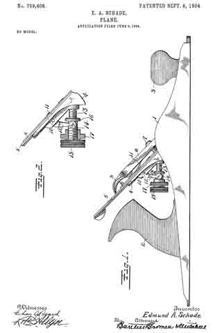
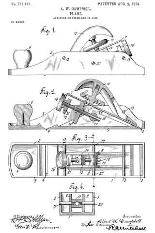
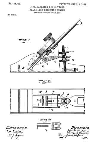
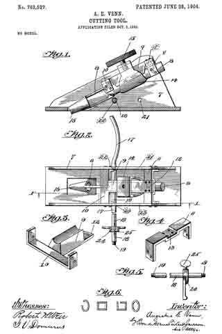
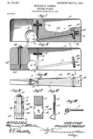
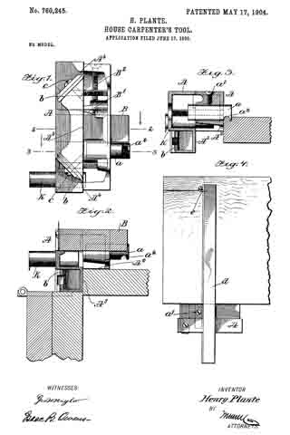
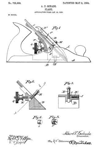
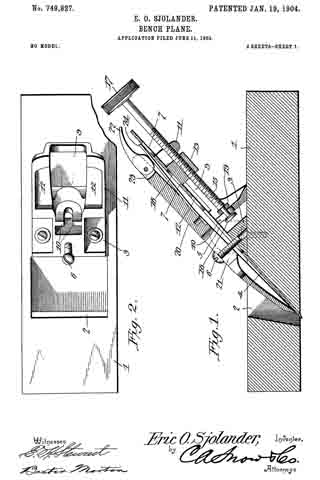
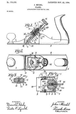
In the accompanying drawings, Figure 1 is a side elevation, partly in section, of my improved plane. Fig. 2 is a top plan. Fig. 3 is a section on line 3 3, Fig. 1. Fig. at is a section on line 4 4, Fig. 1.

Again referring to the drawings, 1 represents the stock of the plane, which is provided with the bit-opening or throat 2. A combined cap or clamping plate 3 is secured in the cheek-plates of the stock by means of pins 4 and 5. The lower edge of the plate 3 is provided with a knife-edge which is arranged flush with the sole or face of the plane.

Near the top of the plate 3 is formed a boss 6, in which is formed a screw-threaded opening 7. In the side of the boss and communicating with the opening 7 is formed a slot 20, and the opposite side of the boss is cut away, as at 21. In the screw-threaded opening 7 is arranged a screw-threaded plug 8, in which is formed an opening 9, the axis of which is at a right angle to the axis of the opening 7, and said opening is screw-threaded the greater part of its length. An adjusting-arm 10 is screw-threaded at one end and is arranged to screw into the screw-threaded opening 9 in the plug 8. The plug 8 therefore forms the fulcrum for the single adjusting-arm 10. In the end of the arm 10 is formed a screw-threaded bore 11. A small block 12 is provided with a screw-threaded stem 13, arranged to screw into the bore 11 in the end of the adjusting-arm 10. The exterior screw-thread on the lever 10 and the screw-thread in the plug 8 are preferably right-hand screw-threads, and the internal screw-threads in the end of the lever 10 and the screw-thread on the stem 13 are preferably left-hand screw-threads. In the block 12 is mounted a set-screw 14, which is provided with a reduced end portion 15. The arm 10 is preferably provided with a knob 16. A support 17 is rigidly secured between the cheek-plates of the stock, and between this support 17 and the plate 3 is arranged a bit 18. In this bit are formed a series of holes 19, arranged to receive the end of the set-screw 14, so as to secure the bit to the plate 3 and clamp it against the support 17.

The construction and operation of my plane is so simple that it can be readily understood.

When the knob of the arm is turned to the right, the end of the arm will be screwed down into the plug, thereby advancing the block and causing the bit which is secured thereto to project through the throat of the plane. By turning the knob of the arm to the left the arm will be screwed out of the plug, drawing the block into the plug and retracting the bit in the throat of the plane. Again, by swinging the arm to the left or to the right on the plug as a fulcrurn the opposite edges of the bit can be caused to project through or be retracted in the throat of the plane, thereby securing perfect alinement of the edge of the bit with the sole or face of the plane.

I have described and illustrated my preferred construction; but it will be readily seen that the same can be changed without departing from the spirit of my invention. For instance, most of the screw-threads are provided only for the purpose of allowing the members to rotate in their respective mountings, and any method of mounting which will permit a rotary movement of the members can be substituted and all screw-threads omitted except one on the arm 10 and a corresponding screw-thread either in the plug 8 or on the block 12 and any other means substituted which will allow a free rotary movement and supply a connecting or binding means at the same time.

What I claim is —

1. A plane comprising a stock, a stationary plate, an arm fulcrumed on said plate, and arranged to have both an oscillatory and a rotary movment, a bit, means for causing the arm to travel longitudinally when rotated, and means forming an operative connection between said arm and said bit so that the rotary movement of said arm will cause a longitudinal movement of said bit and the oscillatory movement of said arm will cause a lateral shifting of said bit so as to aline the cutting edge of said bit with the face of the plane.

2. A plane comprising a stock, a stationary plate, a fulcrum rotatably mounted on said plate, an arm rotatably mounted in said fulcrum, a bit, means for causing the arm to travel longitudinally when rotated, and means for forming an operative connection between said bit and said arm so that the rotary movement of said arm will cause a longitudinal movement of said bit and the oscillatory movement of said arm will cause a lateral shifting of said bit, for the purpose set forth.

3. A plane comprising a stock, a stationary plate, a fulcrum rotatably mounted on said plate and provided with a screw-threaded opening, an arm arranged to screw into said screw-threaded opening, a block, means for securing said block to the end of said arm so as to allow the arm to rotate without rotating said block, a bit, and means for securing said block to said bit.

4. A plane comprising a stock, a stationary plate, a fulcrum rotatably mounted on said plate and provided with a screw-threaded opening, an arm adapted to screw into said fulcrum, a block, means for securing said block to the end of said arm so as to allow the arm to rotate without rotating said block, a bit, and a set-screw for securing said bit to said block.

5. A plane comprising a stock, a stationary plate, a fulcrum rotatably mounted on said plate, an arm arranged to screw into said fulcrum, a block arranged to screw on the end of said arm, a bit and means for securing said block to said bit.

6. A plane comprising a stock, a stationary plate, a fulcrum rotatably mounted on said plate, an arm arranged to screw into said fulcrum and havinga screw-threaded bore in its lower end, a block, a screw-threaded stem formed on said block and arranged to screw into the end of said arm, a bit and means for securing said bit to said block.

7. A plane comprising a stock, a stationary plate, a fulcrum rotatably mounted on said plate, an arm arranged to screw into said fulcrum, a block secured on the end of said arm so as to allow the arm to rotate without rotating the said block, a support, a bit arranged between said plate and said support and a set-screw mounted in said block and arranged to secure the said block to the said bit and clamp said bit between said plate and said support.

8. A plane comprising a stock, a stationary plate, a fulcrum rotatably mounted on said plate, an arm arranged to screw into said fulcrum and having a screw-threaded bore, a block provided with a screw-threaded stem arranged to screw into the bore in said arm, a support, a bit arranged between said plate and said support and a set-screw mounted in said block and arranged to secure said block to said bit and clamp said bit between said plate and said support.

9. A plane comprising a stock, a stationary plate, an arm having a screw-threaded end rotatably secured on said plate, a block provided with a screw-thread arranged to engage the screw-thread on said arm, a bit, and means for securing said bit to said block.

10. A plane comprising a stock, a stationary plate, a fulcrum rotatably mounted on said plate, an arm rotatably secured in said fulcrum and having a screw-threaded bore formed in the end thereof, a block, a screw-thread formed on said block and arranged to screw into the bore of said arm, a bit and means for securing said block to said bit.

11. A plane comprising a stock, a stationary plate, a fulcrum mounted on said plate, an arm rotatably secured in said fulcrum and provided with a screw-threaded end, a block provided with a screw-thread arranged to engage the screw-thread on said arm, a bit and means for securing said bit to said block.

12. A plane comprising a stock, astationary plate, an arm having a screw-threaded bore formed in the end thereof, means for rotatably securing said arm on said plate, a block, a screw-threaded stem formed on said block and arranged to screw into the bore in said arm, a bit and means for securing said block to said bit.

13. A plane comprising a stock, a stationary plate. a fulcrum rotatably mounted on said plate, an arm, means for securing said arm on said fulcrum to oscillate and also to rotate therein. a bit and means for securing said bit to said arm, the arrangement being such that the rotary movement of said arm will cause a longituclinal movement of said bit, and the oscillatory movement of said arm will cause a lateral shifting of said bit for the purpose set forth.

In testimony whereof I sign the foregoing specification, in the presence of two witnesses, this 9th day of May, 1903, at Cleveland, Ohio.

JOHN MUEHL.

Witnesses:
VICTOR G. LYNCH,
G. M. HAYES.

No. 771,463 – Molding Or Beading Plane (Charles C. Crossley) (1904)

[paiddownloads id=”609″]771463


UNITED STATES PATENT OFFICE.

_________________

CHARLES C. CROSSLEY, OF NEW BRITAIN, CONNECTICUT.

MOLDING OR BEADING PLANE.

_________________

SPECIFICATION forming part of Letters Patent No. 771,463, dated October 4, 1904.
Application filed February 13, 1904. Serial No. 193,362. (No model.)

_________________

To all whom it may concern:

Be it known that I, CHARLES C. CROSSLEY, of New Britain, in the county of Hartford and State of Connecticut, have invented a new and useful Improvement in Molding or Beading Planes; and I do hereby declare the following, when taken in connection with the accompanying drawings and the letters of reference marked thereon, to be a full, clear, and exact description of the same, and which said drawings constitute part of this specification, and represent, in —

Figure 1, a side view of a plane containing a cutter constructed in accordance with my invention; Fig. 2, a bottom view thereof; Fig. 3, a side view of the lower end of the cutter detached; Fig. 4, a front view of the same; Fig. 5, a perspective view of the cutter looking at the rear; Fig. 6, an outline of the cutting edge; Fig. 7, a sectional view of a block showing a single cut; Fig. 8, a similar view with two cuts; Fig. 9, a similar view with three cuts; Fig. 10, a plan view of a block showing cuts made at right angles.

This invention relates to an improvement in molding or beading planes, and particularly to the cutters therefor, the object of the invention being to so form the cutter that it may be used in stocks of ordinary construction and by which beads may be cut in every direction and, if desired, at angles to each other; and the invention consists in the construction as hereinafter described, and particularly recited in the claim.

In carrying out my invention I employ a stock A, which may be a center-bead stock, as shown, or a side-bead stock, having the usual mortise B for the reception of a cutter C, which is held in place by the usual wedge D. The operating edge of the cutter has a central half-round portion E, horizontal lower cutters F, and upwardly-extending side cutters or lips G, the end of the cutter being so formed that the cutting edges of the lower critters F are in rear of the cutting edge of the center portion E, whereby a drawing cut is made which assists in cutting smoothly and in any direction as regards the grain of the wood.

The plane is operated in the usual manner and if used upon the surface of wood the first cut will form a half-round bead H, with grooves I on opposite sides thereof, the outer walls of the grooves being straight, as shown in Fig. 7. If two beads are desired, the plane is moved to one side, so that one of the cutters F and the lip G ride in the groove formed at one side of the half-round bead H, which forms a guide for the plane and allows the central portion of the cutter to form a second half-round bead J and a groove K at one side, having a straight side wall, as shown in Fig. 8, or three beads may be formed, as shown in Fig. 9, and this can be continued indefinitely. In Fig. 10 of the drawings I have shown beads L and M crossing each other at right angles, and, as before stated, with my improved cutters these beads may be formed in any direction.

Having fully described my invention, what I claim as new, and desire to secure by Letters Patent, is —

In a plane, the combination with the stock, of a cutter having a central rounded cutting edge, straight cutters on opposite sides of the center and in rear thereof, and side cutters or wings extending upward and forward therefrom, substantially as described.

In testimony whereof I have signed this specilication in the presence of two subscribing witnesses.

CHARLES C. CROSSLEY.

Witnesses:
AARON DANIELSON,
CHAS. A. ERICSON.

No. 769,408 – Plane (Edmund A. Schade) (1904)

[paiddownloads id=”608″]769408


UNITED STATES PATENT OFFICE.

_________________

EDMUND A. SCHADE, OF NEW BRITAIN, CONNECTICUT, ASSIGNOR TO STANLEY RULE & LEVEL COMPANY, OF NEW BRITAIN, CONNECTICUT, A CORPORATION OF CONNECTICUT.

PLANE.

_________________

SPECIFICATION forming part of Letters Patent No. 769,408, dated September 6, 1904.
Application filed June 4, 1904. Serial No. 211,073. (No model.)

_________________

To all whom it may concern:

Be it known that I, EDMUND A. SCHADE, a citizen of the United States, residing at New Britain. in the county of Hartford, State of Connecticut, have invented certain new and useful lmprovements in Planes, of which the following is a full, clear, and exact description.

My invention relates to improvements in planes.

The object of my invention is to provide means for adjustment of the plane-iron and means for locking the same to prevent accidental movement.

The invention consists in improvements the principles of which are illustrated in the accompanying single sheet of drawings.

Figure 1 is a side elevation of a plane embodying the improvements of my invention. Fig. 2 is a detail fragmentary view showing the parts particularly necessary for comprehension out my improvement, a portion of the figure being shown in section.

1 indicates the body of a plane of any suitable construction. This in the form shown has handles 2 and 3. 4 is a frog of any suitable construction which provides a bearing for the plane-iron 5. 6 is a plate winch serves to reinforce the plane-iron and in this particular instance affords the means of connection for the adjusting mechanism. 7 is a cap-screw which takes into the frog in any well-known manner. 8 is a cap coacting therewith, and 9 is a clamp for holding the parts in their proper position. All of these parts thus far described may be of any suitable construction.

The cutting depth or position of the plane-iron may be varied by means of a lever, which is commonly termed a “Y adjustment.”

In the drawings, 10 indicates a pivot-pin carried by the frog and upon which the adjustment-lever is mounted.

11 is the nose of the lever, and 12 is one of the depending arms.

13 is a screw-post which is securely fastened to the frog 4.

14 is an operating-sleeve mounted to operate on the post 13 and having, preferably, a milled head 15.

16 is a shoulder or flange carried by the inner end and adapted to coact with the arm 12 of the adjusting-lever.

17 is a member which is carried by the sleeve 14. This aliords a bearing for one side of the arm 12 of the Y adjustment, so that when the sleeve 14 is moved longitudinally on the post 13 the arm 12 is rocked to and fro to move the cutting-iron.

The adjusting-sleeve 14; as commonly constructed is likely to accidentally turn and move on the post 13 as the plane is used. This results sometimes in derangement of the adjustment of the plane and at all times tends to wear the parts unduly. By my construction this is avoided. The member 17 is preferably milled on the edge and may be adjusted on the post 14 to securely engage the arm 12 and clamp the same in position against the flange 16. The friction of the parts against the arm 12 serves to prevent the adjusting-sleeve from rotating on the post 13. As a consequence the adjusting-lever cannot move and the sleeve has no free play to cause wear on the parts. The plane-iron may be adjusted by releasing the clamping mernber 17 and then operating the adjusting-sleeve. The advantages of this construction will be apparent to those skilled in this art.

What l claim is —

1. In a plane, the combination of a body portion, a frog, a plane-iron and adjusting member, a post, a sleeve adjustable on said post and coacting with said member and a clamping member mounted on said sleeve and also coacting with said member for the purpose specified.

2. In a plane, the combination of a body portion, a frog, a plane-iron, an adjusting member coasting therewith, a screw-threaded post, an adjusting-sleeve screw-threaded on said post, a clamping-sleeve screw-threaded on said adjusting-sleeve and rotatable therewith and also independently thereof said sleeve and clamping member coacting with said adjusting member for the purpose specified.

Signed at New Britain, Connecticut. this 1st day of June, 1904.

EDMUND A. SCHADE.

Witnesses:
H. S. WALTER,
W. J. WORAM.

No. 766,491 – Plane (Albert William Campbell) (1904)

[paiddownloads id=”607″]766491


UNITED STATES PATENT OFFICE.

_________________

ALBERT WILLIAM CAMPBELL, OF GLASTONBURY, ENGLAND, ASSIGNOR TO THE STANLEY RULE & LEVEL COMPANY, OF NEW BRITAIN, CONNECTICUT, A CORPORATION OF CONNECTICUT.

PLANE.

_________________

SPECIFICATION forming part of Letters Patent No. 766,491, dated August 2, 1904.
Application filed February 19, 1904. Serial No. 194,429. (No model.)

_________________

To all whom it may concern:

Be it known that I, ALBERT WILLIAM CAMPBELL, a citizen of Great Britain, residing at Glastonbury, in the county of Somerset, England. have invented certain new and useful Improvements in Planes, of which the following is a full, clear, and exact description.

My invention relates to improvenients in planes, and particularly to adjusting mechanism for double-ended planes.

The object of the invention is to provide a simple and inexpensive means for adjusting the plane-iron in a double-ended plane, which adjusting means shall be reversible to cooperate with the plane-iron in either its front or rear position, so as to vary the cutting depth when desired.

The invention consists in providing, first, a plane-body having two openings or throats in the sole portion and supports for the plane-iron for both of these throats; second, a plane-iron and a clamping member with means for holding them in place; third, adjustable and reversible means for projecting or retracting the plane- iron through either one of the throats, as desired.

The details of my invention will be more clearly seen on an inspection of the accompanying single sheet of drawings, in which —

Figure 1 is a side elevation of a plane embodying the improvements of my invention, the plane-iron being projected through the forward throat. Fig. 2 is a central longitudinal section of the plane with the iron projected through the rear throat. Fig. 3 is a plan view of the plane-body and the adjusting mechanism in the position of Fig. 2, the plane-iron and clamp being removed. Fig. 4 is a vertical cross-section taken on the plane of the line 4 4, Fig. 3.

1 indicates the sole portion of the plane. 2 and 3 are the side flanges which reinforce and strengthen the same 4: is the front throat or opening through which the cutting edge of the plane-iron may project.

5 is the rear throat.

6 is a handle which may be conveniently provided at the fore end of the plane.

7 is a plane-iron which at its cutting edge is supported by a portion of the sole.

8 and 9 are supports for the plane-iron 7 intermediate the throats 4; and 5.

10 is a cap member which bears against the plane-iron near the lower end.

11 is a clamping member carried by the cap which coacts with the plane-iron.

12 and 13 are cross-bars supported by the flanges 2 and 3 of the plane. The cap is inserted beneath one of these cross-bars, and the clamp 11 holds the parts in place.

14 is an adjusting-block having a projection 15 at the upper end for coacting with a recess or perforation in the plane.-iron.

16 is an adjusting-screw for coacting with the adjusting-block to move it back and forth, so as to vary the cutting depth of the plane-iron.

17 is a pivoted step for the adjusting-screw.

18 is a washer over which the lower end of the adjusting-screw is riveted to hold the same in place, so as to prevent the adjusting-screw from moving longitudinally with relation to the step 17.

19 and 20 are pivot-screws which extend through the side flanges 2 and 3 and also through the supports 8 and 9 and are screwed into the step 17. The lower end of the adjusting-block is guided between the inner faces of the supports 8 and 9, and thus prevented from rotation with respect to the adjusting-screw. The rotation of the adjusting-screw thus causes longitudinal movement of the plane-iron.

21 is a wheel or roller carried by the adjusting-screw 16, which rests upon the cross-bar 12 when the parts are in the position shown in Fig. 2. This supports the adjusting-screw toward the upper end. Of course when the plane-iron is reversed the cap 10 is inserted under the rod 12 and the wheel 21 rests on the rod 13, the adjusting and clamping means being reversible and interchangeable in this respect.

It will be obvious to one skilled in the art that many changes and alterations might be made in the construction shown in the drawings without departing from the spirit or scope of my invention.

What I claim is —

1. In a double-ended plane, a body portion having two throats, a plane-iron and reversible means for adjusting the cutting depth of the iron at either throat.

2. Adouble-ended plane comprising a body portion having two throats, a plane-iron and a pivoted reversible means for adjusting its cutting depth of said plane-iron through either of said throats.

3. A plane comprising the combination of a body portion with two throats, a step, pivots therefor, a screw coacting with said step and an adjusting-block operated by said screw.

4. In a plane, a body portion having side flanges and two throats in the sole, a plane-iron, clamping means therefor, two rods connecting said flanges, supports between said throats for said iron, a step, an adjusting-screw for said iron coacting with said step and adapted to coact with either one of said rods for support.

5. In a plane, a. body portion having two throats, supports between said throats, a plane-iron, a reversible adjusting-block therefor, a guide for said block to the rear of each throat to prevent its rotation and a screw coacting with said block for the purpose specified.

6. In a plane, a body having two throats, two supports therein, a plane-iron, a step pivotally mounted between said supports, an adjusting-block, and a screw coacting with said step and said block.

Signed at Shepton Mallet, in the county of Somerset, England, this 4th day of February, 1904.

ALBERT WILLIAM CAMPBELL.

Witnesses:
P. MAGGS,
T. E. RUSSELL.

No. 766,473 – Plane (Justus A. Traut) (1904)

No. 766,473 – Plane (Justus A. Traut) (1904)

[paiddownloads id=”606″]766473


UNITED STATES PATENT OFFICE.

_________________

JUSTUS A. TRAUT, OF NEW BRITAIN, CONNECTICUT, ASSIGNOR TO THE STANLEY RULE &
LEVEL COMPANY, OF NEW BRITAIN, CONNECTICUT, A CORPORATlON OF CONNECTICUT.

PLANE.

_________________

SPECIFICATION forming part of Letters Patent No. 766,473, dated August 2, 1904.
Application filed January 7, 1904. Serial No. 188,049. (No model.)

_________________

To all whom it may concern:

Be it known that I, JUSTUS A. TRAUT, a citizen of the United States, residing at New Britain, in the county of Hartford, State of Connecticut, have invented certain new and useful Improvements in Planes, of which the following is a full, clear, and exact description.

My invention relates to improvements in planes.

The object of the invention is to provide a plane of a simple and reliable construction which may be employed in the usual manner or reversed, as in double-ended planes, and adjusted to vary the cutting depth of the plane-iron.

The invention consists in employing, in a plane-body having two throats or openings, one in the plane near the front end and the other near the opposite or rear end, a pivoted step or yoke midway between two inclined guideways, with which coacts an adjusting-screw, one portion of the screw coacting with a block slidable upon either one of the inclined guides to adjust the plane-iron.

Details of the improvement will be more plainly seen on an inspection of the accompanying single sheet of drawings, in which —

Figure 1 is a side elevation of a plane embodying the improvements of my invention. Fig. 2 is a longitudinal section of the same, the front handle being, however, broken away and the operating parts shown in position with the plane-iron at the front opening or throat. Fig. 3 is a longitudinal section of a plane embodying my improvement with the parts reversed, showing the plane-iron adjusted through the rear throat or opening, Fig. 4 is a plan view of my improved plane, the parts being shown in the position of Fig. 2. Fig. 5 is a cross-sectional view of the plane taken through the pivotal screw-step, the plane-iron and adjusting-screw being removed, showing the step hanging down in the position which it occupies when these parts are removed. Fig. 6 is a cross-sectional view of the adjusting-block through which the adjusting-screw passes and which serves to extend or retract the plane-iron.

1 indicates the body of the plane.

2 is the throat toward the forward end of the plane through which the plane-iron is adapted to project, and 3 is the throat near the rear end of the plane-body.

4 is a plane-iron of suitable construction.

5 is the plane-iron cap for holding the plane-iron securely in place. In the form of my invention herein shown this plane-iron cap terminates at the upper end in a handle portion 6.

7 is a clamping-lever of suitable construction.

8 and 9 are screws which take into the posts 10 and 11, respectively, and for the purpose of coacting with the plane-iron cap for holding it in place.

12 and 13 are oppositely-inclined ways at the rear and front of the plane, respectively, which afford guides for the adjusting-block 14.

15 and 16 are projections from the block 14, adapted to coact with recesses in the rear of the plane-iron 4.

17 is a thumb-nut for operating the adjusting-screw. The threaded portion 18 of the screw coacts with the adjusting-block M.

19 is a step for the adjusting-screw in the form of a yoke which has a screw-threaded portion to correspond with the screw-threads 20 on the adjusting-screw. It will be noted that the pitch of the screw 20 is greater than the pitch of the screw 18. In this instance it is exactly twice, in order that when the thumb-nut 13 is turned in one direction or the other the adjusting-block 14 may move correspondingly as the resultant of the difference between the pitches of the screws.

21 and 22 are pivot-pins for the step 19, which pass through the lugs 23 and 24, which are preferably cast integral with the body of the plane on either side.

25 and Q6 are small grooves cut in the upper surface of the base of the plane to allow slight clearance for the lower end of the adjusting-screw when it is being operated and reversed. Ordinarily the plane is used with the parts in the position as shown in Figs. 1, 2, and 4. When, however, it is desired to use the plane in a corner or some other position, the parts may be reversed, as shown in Fig. 3. To reverse the parts, the cap 5 and the iron 4 are removed after releasing the lever 7, when the adjusting-screw and adjusting block and step may be swung over to the position shown in Fig. 3, the parts pivoting on the axis of the pins 21 and 22. In this position the parts may be again assembled, as shown in Fig. 3, when the plane will operate as before.

The construction will be seen to be simple and not at all likely to become injured or disarranged accidentally, and yet the reversal or adjustment of the parts in either of their positions may be effected without difliculty.

What I claim is —

1. In a plane in combination a body portion, having two throats, a plane-iron, a pivoted step, an adjusting-block, an adjusting-screw coacting with said block and said step and oppositely-inclined guideways forming supports for said adjusting-block.

2. In a plane, a body portion having a plurality of throats, a plane-iron, acap, inclined guideways and cap-screws for said iron toward each of said throats, clamping means and reversible means for manually adjusting the cutting depth of said plane-iron through either of said throats.

3. In a plane, a body portion having two throats, a plane-iron, a cap, cap-screws and a clamp for supporting said iron in position at either throat, and reversible adjusting means coacting with said iron in either position for varying its cutting depth.

4. In a plane, a body having two throats, a plane-iron, a cap, cap-screws, a clamping-lever and a reversible adjusting-block and means for moving said block to adjust the plane-iron through either throat as may be desired.

Signed at New Britain, Connecticut, this 31st day of December, 1903.

JUSTUS A. TRAUT.

Witnesses:
H. S. WALTER,
W. J. WORAM.

No. 763,721 – Plane-Iron-Adjusting Device (John W. Carleton And George E. Trask) (1904)

[paiddownloads id=”605″]763721


UNITED STATES PATENT OFFICE.

_________________

JOHN W. CARLETON AND GEORGE E. TRASK, OF NEW BRITAIN, CONNECTICUT, ASSIGNORS TO
UNION MANUFACTURING COMPANY, OF NEW BRITAIN, CONNECTICUT, A CORPORATION.

PLANE-IRON-ADJUSTING DEVICE.

_________________

SPECIFICATION forming part of Letters Patent No. 763,721, dated June 28, 1904.
Application filed October 26, 1903. Serial No. 178,477. (No model.)

_________________

To all whom it may concern:

Be it known that we, JOHN W. CARLETON and GEORGE E. TRASK, citizens of the United States, residing at New Britain, in the county of Hartford and State of Connecticut, have invented certain new and useful Improvements in Plane-Iron-Adjusting Devices, of which the following is a specification.

Our invention relates to improvements in plane-iron-adjusting devices; and the object of our improvement is convenience and efficiency in use.

In the accompanying drawings, Figure 1 is a sectional side elevation of our plane-iron adjustment, together with so much of a plane as is deemed necessary to show its connection therewith. Fig. 2 is a plan view of the major part of the said adjusting devices and a portion of the plane-stock, the upper adjusting-nut and the plane-irons being removed. Fig. 3 is a plan view of the longer arm of the operating-lever in a modified form.

Our improvement relates to the longitudinal adjustment of the plane-iron or cutting-bit when frictionally held in place on its seat by a bit-clamp.

A designates the stock, which may be of any known or ordinary construction.

3 is the hub of the operating-lever, the said lever having a short arm or tooth 4 for engaging the cap-iron 5 and a longer operating-arm 6 by which to move the said lever. The cap-iron 5 is secured by a screw 7 to the plane-iron or cutting-bit 8 in the ordinary manner, so that when in use the said cap is rigid with the plane-iron, whereby moving the cap longitudinally also moves the plane-iron longitudinally. Any known connection of the short arm or tooth of the lever with the plane-iron may be substituted for the cap connection therewith which is herein shown. The plane-iron 8 is seated in the ordinary position on a fixed seat of the stock A, and underneath this plane-iron the operating-lever 3 4 6 is pivoted in any proper manner — as, for example, by the pin 9, which extends through the hub 3 of the said lever and uprights or supports 10 of the stock. The longer arm 6 of the operating-lever is provided with an opening for the admission of the screw-post 11 that is rigidly mounted on the stock and projects upwardly at substantially a right angle to the length of the said operating-arm when the said arm is in its central or intermediate position. This opening may be in the form of a slot 12 near the outer end of the said arm, as shown in Fig. 2, or a notch 13, that extends from the outer end of the said arm inwardly, as shown in Fig. 3. Two separate adjusting-nuts 14 are mounted on the screw-post 11, one of the said nuts being above the operating-arm and the other below it. The upper one of these nuts is removed in Fig. 2.

The operating-lever, substantially as herein shown and described, without the screw-post and nuts is older than the date of the invention upon which this application is based, and hence the said lever of itself is not claimed herein.

The outer end of the longer arm 6 of the operating-lever constitutes a handle by means of which the lever when free may be moved in either direction. The two separate adjusting-nuts 14 are each single-acting nuts for acting on one side only of the lever. The friction of the ordinary bit-clamp is depended upon to hold the cutting-bit and the operating-lever in their places when one or both of the nuts are out of contact with the said lever.

With our improvement when both nuts are turned so as to bear snugly against the opposite sides of the longer arm of the operating-lever the said lever is positively held against moving in either direction. If it is desired to raise the outer end of the operating-arm for adjusting the plane-iron downwardly and outwardly, the upper nut is loosened a little and the opposing or under nut tightened up, and vice versa. The operator can readily see which way to move the nuts to effect the desired adjustment. Some workmen never lay away the plane without first drawing the plane-iron inwardly so as to protect its cutting end. Then when they begin work again the plane-iron has to be readjusted. With our adjustment when it is desired to draw in the plane-iron to protect the cutting end it is only necessary to loosen the lower nut a little and then depress the outer end of the operating-arm by the application of one’s finger or thumb without moving the upper nut at all. Then when the plane is again wanted for use it. is only necessary to raise the operating-arm of the lever by means of the handle until it is stopped by the upper nut. Then bring the lower nut up into place to bind the said arm against the upper nut and the cutting-bit will be restored to the particular adjustment that it had when laid away. In this connection it may be noted that there is a complete and operative combination with the outer nut only, the upper nut as herein shown-that is to say, when the lower nut is run down so as to be out of action the lever may be brought up against the upper nut as a stop, and the cutting-bit will be thus adjusted to whatever position the said nut may be set and with substantially the same degree of fineness that can be had with the ordinary double-acting nut that always leaves the lever free in one direction to a limited extent. Thus when only the upper one of the nuts is employed and the desired adjustment has been made the operator may depress the lever to draw in the edge of the cutting-bit for laying the plane away and on resuming work may force the cutting edge out again by merely raising the handle until the lever strikes the said upper nut. The friction caused by the bit-clamp will hold the bit in its adjusted positien, and it will be adjusted with a fair degree of accuracy. By the use of the two single-acting nuts, when both are firmly seated in place, all the give or spring of the parts is taken up so as to make the adjustment positive. Now by first loosening one nut and then tightening up the other to move the lever either way from this positive or rigid adjustment we are enabled to adjust the cutting-bit with the iinest kind of action. At the same time the lower nut may be readily spun down out of the way for permitting the cutting-bit to be moved in and out by hand in the manner before described.

It is apparent that some changes from the specific construction herein disclosed may be made, and therefore we do not wish to be understood as limiting ourselves to the precise form of construction shown and described, but desire the liberty to make such changes in working our invention as may fairly come within the spirit and scope of the same.

We claim as our invention —

1. In a plane, the combination of a cutting-bit with a bit-clamp for frictionally holding the said bit in place on its seat, a lever for moving the said cutting-bit longitudinally on its seat under the said bit-clamp, the said lever having a short arm connecting it with the said cutting-bit, and a longer operating-arm having a handle, a fixed screw extending in the line of movement of the said operating-arm and a single-acting nut mounted on the said screw at the outer side of the said arm and acting on the said side only, leaving the lever free to be moved by the handle in the direction for withdrawing the edge of the cutting-bit substantially as described.

2. In a plane, the combination of a cutting-bit with a bit-clamp for frictionally holding the said bit in place on its seat, a lever for moving the said cutting-bit longitudinally on its seat under the said bit-clamp, the said lever having a short arm connecting it with the said cutting-bit and a longer operating-arm having a handle, a fixed screw extending in the line of the movement of the said operating-arm, a single-acting nut mounted on the said screw at one side of the said operating-arm for acting on that side only, and a second single-acting nut mounted on the said screw at the opposite side of the said operating-arm for acting on that side only, substantially as described.

JOHN W. CARLETON.
GEORGE E. TRASK.

Witnesses:
N. G. CURTIS,
H. H. WHEELER.

No. 763,527 – Cutting-Tool (Augustus E. Venn) (1904)

[paiddownloads id=”604″]763527


UNITED STATES PATENT OFFICE.

_________________

AUGUSTUS E. VENN, OF CHICAGO, ILLINOIS.

CUTTING-TOOL.

_________________

SPECIFICATION forming part of Letters Patent No. 763,527, dated June 28, 1904.
Application filed October 5, 1903. Serial No. 175,902. (No model.)

_________________

To all whom it may concern:

Be it known that I, AUGUSTUS E. VENN, a citizen of the United States, residing at Chicago, in the county of Cook and State of Illinois,have invented certain new and useful Improvements in Cutting-Tools, of which the following is a specification, reference being had to the accompanying drawings.

My invention relates to cutting-tools, and particularly to tools adapted to cut grooves in wood or other material to be operated upon; and its object is to provide a new and improved means by which, by the rotation of the cutter in the tool, grooves of different shapes may be cut in the work.

In the drawings, Figure 1 is a longitudinal vertical section on line 1 1 of Fig. 2. Fig. 2 is a top or plan view with one of the handles broken away. Fig. 3 is an enlarged detail, being an isometric view of a part of the support by means of which the cutter is secured to the stock. Fig. 4 is an enlarged detail, being an isometric view of a cross-bar by which one end of the support shown in Fig. 3 is secured to the stock. Fig. 5 is a detail, being a view of the gage, partly broken away; and Fig. 6 is a diagrammatic view showing several shapes which may be given to the cutting edge of the cutter.

As shown in the drawings and as preferably constructed, my invention is embodied in the form of a grooving-plane.

7 indicates the stock, and 8 the bit or cutter.

9 indicates a support which is provided with a cross-piece 10, preferably integral therewith, having its two ends bent up at right angles, as is best shown in Fig. 3, and of such length as to fit closely between the sides of the stock 7. The under side of the support 9 is rounded out, as is best shown in Fig. 3, to conform to the shape of the handle of the bit or cutter 8.

11 indicates a cross-piece which is bent at right angles at its ends and is of such length that the bent-up ends may fit snugly between the sides of the stock 7.

The support 9 is provided at the opposite end from the cross-piece 10 with a projection 12, and the cross-piece 11 is provided with a recessed portion 13 on its upper side, into which the projection 12 will snugly fit.

14 indicates a stirrup which is adapted to surround the rounded portion of the bit or cutter 8 and to pass around the support 9. It is provided on its upper surface with a screw-threaded opening into which a thumb-screw 15 may be screwed.

The bent ends of the cross-piece 10 and of the cross-piece 11 are provided with suitable screw-threaded openings by means of which they may be secured between the sides of the stock. The projection 12 of the support 9 is provided with screw-threaded openings and the recessed portion of the cross-piece 11 with corresponding openings, through which screws may pass to engage the screw-threaded openings in the projection 12 for the purpose of fastening the parts together.

The support 9 is placed between the sides of the stock with its hollowed rounded surface facing downward and is secured to the stock by suitable screws passing through the sides of the stock and into the screw-threaded openings in the bent ends of the cross-piece 10. The stirrup 14 is then placed in position around the support 9, the cross-piece 11 placed in position and fastened by screws to the sides of the stock, and the projection 12 is secured in place in the recess 13 by means of suitable screws.

The bit 8 is cylindrical at its upper end and is provided at its lower end with a cutting portion 16. The bit is provided with a proper clearance above the cutting portion, through which the shavings may pass, as is best shown in Fig. 2.

The cutting edge of the tool may be of various shapes, of which several are illustrated in Fig. 6. The cutter, being placed in position between the support 9 and the stirrup 14, may be adjusted longitudinally of itself, so that a proper amount of the cutting edge may project below the sole of the stock 7 through the usual opening therein, and is locked in position by turning the thumb-screw 15, which will cause the stirrup 14 to move up toward the support 9, firmly binding the cylindrical portion of the cutter between the stirrup and the support. It will be obvious that by rotating the cutter 8 upon its longitudinal axis, which it is obvious can be accomplished by loosening the set-screw 15 and then screwing it home when the desired amount of rotation is made, a different-shaped cutting edge will project below the sole of the stock 7 and a different-shaped groove thereby cut in the work.

17 (see Fig. 2) indicates handles, of which one is cut away upon one side to show the gage hereinafter described. The handles are secured to the stock in any appropriate way.

18 indicates a pin which is cylindrical in shape and has upon its ends screw-threaded portions 19. The sides of the stock 7 are provided with cylindrical openings 20 21, through which the cylindrical pin 18 may pass, and opposite the openings 20 21 are screw-threaded openings 22 23, which are adapted to engage with the screw-threaded ends of the pin.

24 indicates a gage which is provided with a suitable opening through which the pin 18 passes and which is secured in any desired position upon the pin 18 by means of a set-screw 25. It will be obvious that by this construction the gage can be used upon either side of the tool.

That which I claim as my invention, and desire to secure by Letters Patent, is —

1. The combination with a support, of a bit-iron mounted in said support adjustable longitudinally of itself therein and adapted to be rotated on its longitudinal axis and by its rotation to present a different-shaped cutting edge to the work, and means for locking said bit-iron in any desired position, substantially as described.

2. The combination with a plane-stock, of a bit-iron mounted in said stock adjustable longitudinally of itself therein and adapted to project its cutting edge below the sole of said stock, said bit-iron being rotatable on its longitudinal axis and having a cutting edge of such shape that by said rotation of said bit-iron grooves of different shape may be cut, and means for locking said bit-iron in any desired position, substantially as described.

3. The combination with a support of a cutting-tool adjustably mounted in said support adapted to be rotated on its longitudinal axis and having a tubular end provided with a cutting edge adapted by the rotation of said cutting-tool to present a different-shaped cutting edge tothe work, and means for locking said cutting-tool in any desired position, substantially as described.

4. The combination with a stock, a support secured to said stock, a stirrup surrounding said support, a set-screw carried by said stirrup adapted to bear upon one side of said support, a cutter having a shank adapted to be engaged between said support and said stirrup, said cutter being adapted to be rotated upon its longitudinal axis and having a cutting edge of such shape that by the rotation of said cutter grooves of different shape may be cut, substantially as described.

AUGUSTUS E. VENN.

Witnesses:
MINNIE A. HUNTER,
HELEN M. COLLIN.

No. 761,097 – Router-Plane (McCluer H. Parker) (1904)

[paiddownloads id=”603″]761097


UNITED STATES PATENT OFFICE.

_________________

McCLUER H. PARKER, OF LOS ANGELES, CALIFORNIA.

ROUTER-PLANE.

_________________

SPECIFICATION forming part of Letters Patent No. 761,097, dated May 31, 1904.
Application filed December 15, 1903. Serial No. 185,228. (No model.)

_________________

To all whom it may concern:

Be it known that I, McCLUER H. PARKER, a citizen of the United States, residing at Los Angeles, in the county of Los Angeles and State of California, have invented a new and useful Router-Plane, of which the following is a specification.

This invention relates to improvements in router-planes, and particularly to the adjusting and clamping of the cutting knife or bit.

The router-plane forming the present invention is particularly adapted for routing out seats for door butts or hinges and for cutting out for locks and strike-plates for the same. The plane is of value in cutting seats for other building hardware or material that requires inlaying.

The accompanying drawings illustrate the invention, and referring to the same, Figure I is a side view of the router-plane with part of the stock broken away, showing the preferred construction. Fig. II is a side view of the router-plane, with part of the stock broken away, of another form. Fig. III is a bottom view of the form shown in Fig. I. Fig. IV is a view looking toward the nose of the form shown in Fig. II. Fig. V is a section on line V V, Fig. II. Fig. VI is a detail in perspective of the cutter or bit. Fig. VII isa detail in perspective of the clamping-rod.

1 designates the stock, which preferably tapers throughout its length, as shown, being wider at the heel than at the nose.

2 designates the cutting iron or bit, which is provided with a squared shank 3, the upper end of which is threaded, as at 4. The squared shank 3 is received by the stock of the plane in a square hole, and when in position the flat faces of the shank engage the flat faces of the hole to hold the shank from rotation relatively to the stock, the hole extending substantially at right angles to the bottom of the stock, and the cutting-iron 2 projects slightly downward and forward from the rear part of the throat 5 of the stock.

6 is a knurled thumb-nut which is mounted on the threaded shank 3, the stock 1 being slotted to receive the thumb-nut 6, and the edges of the nut protrude, as shown in Fig. III, so as to be readily grasped by the fingers in adjusting the cutting-iron.

7 is a clamping-bar having an eye 8, which is squared internally to receive the shank 3 of the cutting-iron, the shank 3 loosely fitting in the eye. The other end of the clamping-bar 7 is threaded, as at 9. and carries a locking-nut 10, the periphery of which is provided with square notches 11, which afford shoulders against which a tool may be struck-such, for instance, as a nail-set-to tighten the clamping-nut securely.

The stock 1 is slotted to receive the clamping-nut 10, and a washer 12 is provided within the stock 1, against which the locking-nut bears when screwed tight.

As shown, the clamping-bar extends from the rear of the throat 5 nearly to the heel of the plane and is inclined so as to bring the clamping-nut well above the bearing-face or bottom of the stock.

In the preferred form the stock 1 is made of a single piece of wood, and in order to put the clamping-bar in place in the stock the stock is drilled from the heel toward the throat with a hole of sufflcient diameter to allow of the passage through it of the eye 8, and a wooden sleeve 13, which is drilled centrally to receive the locking-bar 7, together with the locking-bar 7, is slipped into the hole in the stock from the heel, the sleeve before being inserted having had glue applied to its surface and the hole in the stock also having had glue applied to its surface, so that when the sleeve is in place in the stock the glue sets and the sleeve becomes practically part of the stock. A plug 14 is then glued into the stock to fill the end of the hole. Another form is shown in Fig. II, in which the lower part of the nose 15 is fastened to the upper part 16 by a tongue-and-groove joint, a tightening-screw 17 passing down through a wide slot 18 in the stock and screwing into the adjustable part 15. When the plane is of metal, it may preferably be constructed in this form and the sleeve 13 may be dispensed with, as the adjustable nose 15 may be moved forward or entirely removed from the stock to permit the locking-bar 7 to be slipped into place in the stock from the front, the hole in the stock in such cases being drilled of a size to just receive the shank of the locking-bar. After the locking-bar is in place the nose 15 may be fastened by tightening the screw 17.

When the lock-nut 10 is screwed up tight, it draws the locking-bar 7 to the rear and forces the shank 3 tightly against its squared seat in the stock 1, and the cutting-iron 2 is thus prevented from turning sidewise or from slipping up or down. To adjust the cutting-iron 2, the lock-nut 10 is loosened, which frees the shank 3, so that the nut 6 may be readily turned by the fingers to raise or lower the cutting-iron 2, and when it has been brought to the desired position the lock-nut 10 is again tightened, being easily forced very tightly into place by inserting a nail-set in a notch of the lock-nut and tapping the same.

I have found in practice that a plane constructed as herein set forth more than doubles the capacity of a mechanic in hinging doors and in doing other similar work and that the grade of work is also improved to a marked degree.

What I claim is —

1. A stock having a throat and having a hole extending substantially at right angles to the bottom of the stock, a cutting-iron having a shank lying in said hole, the shank and the part of the stock engaging therewith being formed with engaging parts to hold the shank from rotation, the shank having a threaded portion and a nut on the threaded portion for adjusting the cutting-iron, and means for clamping the shank.

2. A stock having a throat, and having a hole with a fiat face extending at substantially right angles to the bottom of the stock, a cutting-iron having a shank with a flat face lying in the hole, the shank having a threaded portion, and a nut on the threaded portion for adjusting the cutting-iron, and means for clamping the shank.

3. A stock having a throat, and having a hole with a flat face extending substantially at right angles to the bottom of the stock, a cutting-iron having a shank with a flat face lying in the hole, the shank having a threaded portion, a nut on the threaded portion for adjusting the cutting-iron, means for clamping the shank, and a clamping-bar having an eye through which the shank passes, the clamping-bar having a threaded portion, and a nut on the threaded portion for tightening the clamping-bar.

4. A stock, a cutting-iron having a squared shank threaded at one end, the shank lying within a square hole in the stock and substantially perpendicular to the bottom of the stock, a nut on the threaded portion of the shank within a slot in the stock, a clamping-bar having a squared eye which receives the shank of the cutting-iron, the clamping-bar having a threaded portion, and a nut on the threaded portion in a slot in the stock.

5. A stock, a cutting-iron having a squared shank threaded at one end, the shank lying within a square hole in the stock and substantially perpendicular to the bottom of the stock, a nut on the threaded portion of the shank within a slot in the stock, a clamping-bar having a squared eye which receives the shank of the cutting-iron, the clamping-bar having a threaded portion, and a nut on the threaded portion in a slot in the stock, said latter nut having a notched periphery.

6. A stock, a cutting-iron having a squared shank threaded at one end, the shank lying within a square hole in the stock and substantially perpendicular to the bottom of the stock, a nut on the threaded portion of the shank within a slot in the stock, a clamping-bar having a squared eye which receives the shank of the cutting-iron, the clamping-bar having a threaded portion, a nut on the threaded portion in a slot in the stock, said latter nut having a notched periphery, and a washer between the stock and the forward face of the latter nut.

In testimony whereof I have hereunto signed my name, in the presence of two subscribing witnesses, at Los Angeles, in the county of Los Angeles and State of California, this 7th day of December, 1903.

McCLUER H. PARKER.

Witnesses:
GEORGE T. HACKLEY,
JULIA TOWNSEND.

No. 760,245 – House-Carpenter’s Tool (Henry Plante) (1904)

[paiddownloads id=”602″]760245


UNITED STATES PATENT OFFICE.

_________________

HENRY PLANTE, OF NEW YORK, N. Y.

HOUSE-CARPENTER’S TOOL.

_________________

SPECIFICATION forming part of Letters Patent No. 760,245, dated May 17, 1904.
Application filed June 17, 1903. Serial No. 161,823. (No model.)

_________________

To all whom it may concern:

Be it lrnown that I, HENRY PLANTE, a citizen of the United States, and a resident of the city of New York, borough of Manhattan, in the county and State of New York, have invented a new and Improved House-Carpenter’s Tool, of which the following is a full, clear, and exact description.

This invention relates to an improvelnent on my prior patent for a gage granted February 23, 1886, No. 336,742.

The object of the present invention is to enlarge the capacity of the gage illustrated in my previous patent so as to render the improved tool capable of use in a great number of operations necessary in house-carpentry — for example, in the planing of door-jambs to enable the doors to fit properly, the measurement and cutting out of panels to be inserted into the door, and other parts of the house-fittings and in the use of bead-planes generally, all of which functions are in addition to those embodied in the gage as above disclosed.

This specification is an exact description of one example of my invention, while the claims define the actual scope thereof.

Reference is to be had to the accompanying drawings, forming a part of this specification, in which similar characters of reference indicate corresponding parts in all the views.

Figure 1 is an inverted plan view of the device. Fig. 2 is a section on the line 2 2 of Fig. 1. Fig. 3 is a section on the line 3 3 of Fig. 1, and Fig. 4 is a top plan view illustrating the use of the panel-cutting attachment.

The body A of the gage is provided with the slide B and the tube K, both before employed.

B’ indicates a spring-finger for exerting a frictional tension on the slide B, and B2 indicates a set-screw for adjusting this pressure.

a indicates a tube formed, preferably, of steel and fitted transversely in the body A, as shown best in Fig. 3. a’ indicates a set-screw for adjustably holding the tube a in place. Said tube a is formed with a curved notch a2, passing transversely therethrough immediately adjacent to its end and forming two knife-edges at opposite sides of the tube, enabling it to cut away the wood or other material at a corner therein and form the bead, as indicated in Fig. 3. As shown best in Fig. 1, the tube has a slot a3 formed therein and extending outward from the slot a2 to the end of the tube, this latter slot forming opposite cutting edges, enabling the end of the tube to cut down into the work, as illustrated. By means of this device the tool may be readily employed as a bead-plane, and this will be a great advantage to carpenters, since the operation of beading is very commonly resorted to in house-fitting.

The tool is formed with a longitudinally-extending groove A2 in one of its corners. this groove being in the form of a large rabbet, so as to receive the corner of the jamb of the door, as indicated in Fig. 2, and to allow the face A3 to bear against the jamb. This face A3 is formed with two notches A4 thereon, and in said notches are held the planing-knives b, which are securely adjusted by means of screws c, all of which will be understood from the drawings. These knives are disposed oppositely to each other, so that in reciprocating the tools over the work the knives will alternately be active and also so as to enable the extremities of the jamb both at the top and bottom of the door to be reached by the knives during the planing operation. In this connection it should be understood that the door-step and the top of the door-frame will prevent the plane from being moved completely over the extremities of the jamb; but this difficulty is minimized by providing the two knives oppositely disposed and located, respectively, adjacent to the ends of the tool.

Fig. 4 shows the application of the panel-cutting attachment. In this instance the slide B of Figs. 1 and 2 is removed and a long slide or arm d is used in its stead, this arm having at its outer end a knife e. The arm d is adjusted on the tool so as to place the knife c in the desired position, and then by drawing the blade e along the veneer of which the panel is formed the panel may be properly cut. If necessary, the panel may be reversed and the incision made with the blade e on both sides, these incisions meeting to form the complete cut in the veneer.

In view of my prior patent the use and advantages of my invention will be fuliy understood by persons skilled in the art.

Various changes in the form, proportions, and minor details of my invention may be resorted to at will without departing from the spirit and scope thereof. Hence I consider myself entitled to all such variations as may lie within the intent of my claims.

Having thus described my invention, I claim as new and desire to secure by Letters Patent —

1. A carpenter’s tool, comprising a tube having a transverse cut extending through the walls of the tube and a longitudinal slot extending from the cut-out to the end of the tube to form a beading-plane.

2. A carpenter’s tool, comprising a body having an opening therein, and a tube adjustably mounted in said opening, the tube having a transversely-extending cut in the walls thereof and a longitudinal slot extending from the cut-out to the end of the tube, forming a beading-plane, for the purpose specified.

3. A carpenter’s tool, comprising a body having a planing-surface thereon, a planing-knife juxtaposed to said body, and a tube adjustably mounted in the body and having a transversely-extending cut therein forming a beading-plane.

4. A carpenter’s tool, comprising a body having a planing-surface thereon, two oppositely-disposed planing-knives juxtaposed to said surface and located respectively adjacent to the ends thereof, and an adjustable tube mounted in the body and having a transverse cut therein forming a beading-plane.

5. A carpenter’s tool, comprising a body having a longitudinally-extending groove in one of its corners, a planing-blade mounted on the body and lying with its edge coincident to one of the side walls of said groove, the body also having a transverse groove therein, a slide adjustably mounted in said groove and having a marking device thereon, means for adjustably holding the slide, the body also having an opening extending therethrough, a tube fitted in said opening and open throughout its ends, the tube having a transverse cut extending through its walls at one end portion, and a longitudinal slot extending from the cut-out to the end of the tube, and means for removably holding the tube in place.

In testimony whereof I have signed my name to this speciiication in the presence of two subscribing witnesses.

HENRY PLANTE.

Witnesses:
JNO. M. RITTER,
H. T. BERNHARD.

No. 758,698 – Plane (Albert F. Schade) (1904)

[paiddownloads id=”601″]758698


UNITED STATES PATENT OFFICE.

_________________

ALBERT F. SCHADE, OF NEW BRITAIN, CONNECTICUT, ASSIGNOR TO
STANLEY RULE & LEVEL COMPANY OF NEW BRITAIN CONNECTICUT,
A CORPORATION OF CONNECTIOUT.

PLANE.

_________________

SPECIFICATION forming part of Letters Patent No. 758,698, dated May 3, 1904.
Application filed January 16, 1902. Serial No. 89,958. (No model.)

_________________

To all whom it may concern:

Be it known that I, ALBERT F. SCHADE, a citizen of the United States, residing at New Britain, county of Hartford, State of Connecticut, have invented certain new and useful Improvements in Planes, of which the following is a full, clear, and exact description.

My invention relates to improvements in the construction of planes.

The object of my invention is to provide a simple, inexpensive, and effective device for securing in place the means whereby the position of the cap of the plane is determined, as will be understood from the following description, taken in connection with the accompanying drawings.

In the drawings, Figure 1 is a side elevation of a plane with one side partly broken away to show a detail of construction. Fig. 2 is a longitudinal section of a portion of the plane, showing details of construction. Fig. 3 is a section on the line 3 3, Fig. 2. Figs. 4 and 5 are views of details of construction.

The plane which I have chosen to here describe is an iron plane, in which A is the bottom, and A’ is a side flange.

C is what is commonly termed the “frog,” which is secured by the screw B’ to the bottom between the side flanges and presents an inclined upper surface leading down to the slot in the bottom or base through which the plane-iron C projects. In this type of plane, C’ is the plane-iron cap, the two parts thus forming a plane-iron of double thickness. The iron C furnishes the cutting edge.

D is what is termed the “cap.” In the particular construction shown this cap is provided with a cam D’.

E is what may be termed a “cap-screw” or “holder.” The screw E is ordinarily in the form of a headed screw taking into a tapped hole in the frog B.

The holder E is seldom if ever adjusted after it has been secured in its proper position, and it is desirable to have it snugly retained in position, so that it will not work loose and thus disturb the adjustment of the cap and associated parts. Should the parts become loose, they would chatter and would not properly perform their intended functions. It is desirable not to have a permanent connection in order that in the event of an emergency a new holder or screw E may be inserted and also in order that, if desirable, the same may be adjusted. In case the cap should become broken or lost a new cap must be provided, and if it should happen that the new cap should vary slightly in dimensions from the original cap the holder would have to be adjusted. For that reason it will be seen that while adjustment of the cap-screw is not the common thing, it is, nevertheless, a desirable incident.

F is a lever or Y adjustment pivoted to the frog B, one end of which is adapted to engage with the plane-iron C, the other end being engaged by an adjusting-nut G, movable on a screw or post H, also carried by the frog. The plane-iron may be advanced or retracted relatively to the bottom of the plane by means of the adjusting-nut G, which operates the lever F, engaging with the pl ane-iron and regulating the depth of the cutting edge in the usual manner.

My invention does not relate generally to the construction of the plane and is therefore not limited to any special type of plane, but relates more particularly to an adjustable holding device for the said cap-screw and comprises a means adapted to frictionally bear against the said screw to prevent its turning. This means comprises a shoe I, carried in a hole or passage in the side of the frog B, which hole or passage at its outer end may be screw-threaded to carry an adjusting-screw J. Between the adjusting-screw J and the shoe I is a spring K. The construction and arrangement of the parts are best seen in Fig. 3, in which it will be seen the shoe bears directly against the side of the cap-screw E and with a pressure depending upon the adjustment of the screw J. In practice this has been found sufficient to properly hold the cap-screw in the desired position, and yet it does not so hold it that it cannot be adjusted. It provides a simple, inexpensive, and effective means for accomplishing the desired end, and in operation will not batter or otherwise injure the screw-threads of the cap-screw E. The frog is unseated when it is desired to adjust the screw J. When the cap-screw E is locked by the adjusting-screw J and the frog is seated in the body portion, it is impossible for the screw J to work out and be lost, since it is held in place by the flange A’, which substantially covers the end thereof.

What I claim, and desire to secure by Letters Patent, is —

In a plane the combination of a body having side flanges and a removable frog secured thereto between said flanges, a cap-screw seated in said frog, an adjusting-screw operating in the side of the frog to clamp said cap-screw, the head of said adjusting-screw being held from extraction by one of the side flanges, substantially as described.

ALBERT F. SCHADE.

Witnesses:
A. W. STANLEY,
C. S. HODGE.

No. 755,587 – Scraping-Plane (William Ulses) (1904)

[paiddownloads id=”600″]755587


UNITED STATES PATENT OFFICE.

_________________

WILLIAM ULSES, OF LOS ANGELES, CALIFORNIA.

SCRAPlNG-PLANE.

_________________

SPECIFICATION forming part of Letters Patent No. 744,587, dated March 22, 1904.
Application filed October 29, 1903. Serial No. 179,070. (No model.)

_________________

To all whom it may concern:

Be it known that I, WILLIAM ULSES, a citizen of the United States, residing at Los Angeles, in the county of Los Angeles and State of California, have invented new and useful Improvements in Scraping-Planes, of which the following is a specification.

My invention relates to a plane for finishing surfaces made nearly smooth by the ordinary cutting-planes; and the object thereof is to provide a tool by means of which planed surfaces may be readily finished and with less danger of roughing the surface than if an ordinary scraper were used.

I accomplish this object by the scraping-planes described herein and illustrated in the accompanying drawings, in which —

Figure 1 is a side elevation, with a portion in longitudinal central section taken on the line 1 1 of Fig. 2, of my scraping-plane. Fig. 2 is a view of the sole of my plane.

In the drawings, A is the stock, having a throat B for the reception of the plane-iron C and the binding-wedge D, which secures the plane-iron in the throat, binding it against abutments A’ on the sides of the throat. These abutments are shown in dotted lines in Fig. 1, the inner dotted line representing the top line of the abutments and the outer line representing the bottom line of the abutments. The tops of these abutments project forwardly of the bottoms, so that the top of the plane-iron is inclined forwardly, as shown in Fig. 1, when the wedge and iron are in place. I have found by practical test that an inclination of five-sixteenths of an inch in a stock of two inches in height produces very satisfactory results. The plane-iron is constructed, preferably, of a thin piece of tempered steel having the lower edges C’ thereof sharpened, as shown in Fig. 1, or otherwise formed into a scraping-surface. The front side of the binding-wedge forms the segment of a circle, and when the scraper-iron is secured in the stock it is bent into circular shape, as shown in Fig. 2, which causes the central portion thereof, by reason of the forward inclination of the top, to project through the stock a greater distance than the edges. With a scraper-iron two inches wide I have found that one-sixteenth of an inch produces a very satisfactory curvature and that a plane thus constructed will take out all the tool-marks and perfectly finish the surface. The curvature of the plane-iron caused by the wedge when in place in the stock prevents it from chattering. It will be observed that by this construction the central portion of the iron does its scraping in advance of the side portions, and thereby the danger of catching under the grain of the wood is lessened over that of using a scraper with a straight edge. It will also be observed that when the plane-iron is out of the stock its cutting edge is a perfect straight line and that it can thus be readily sharpened and that when put in place in the stock the edges follow at the rear of the center and are a little elevated above the center, thus preventing any marring of the surface upon which the plane is being used, the edges being preferably placed in the same plane as the sole of the stock.

Having described my invention, what I claim as new, and desire to secure by Letters Patent, is —

1. A scraping-plane comprising a stock having a throat with abutments on the sides and in the front portion thereof; a plane-iron composed of thin resilient metal and having its lower edges formed into a scraping-surface; a rigid binding-wedge of a length substantially equal to the height of the stock having a circular face adapted to pass into said throat back of the scraper-iron and bind said iron in said stock in a forwardly-projecting curved form.

2. A scraping-plane comprising a stock having a throat with abutments on the sides and in the front portion thereof, the tops of said abutments projecting forwardly of the bottom thereof; a plane-iron composed of thin resilient metal and having its lower edge formed into a scraping-surface; a rigid binding-wedge having a circular face adapted to pass into said throat back of the scraper-iron and bind said iron in place in the stock and to produce in said iron a forwardly-projecting curve.

ln witness that I claim the foregoing I have hereunto subscribed my name this 22d day of October, 1903.

WILLIAM ULSES.

Witnesses:
G. E. HARPHAM,
MARGARETÉ C. NICHOLSON.

No. 752,365 – Spokeshave (John H. Spear) (1904)

[paiddownloads id=”599″]752365


UNITED STATES PATENT OFFICE.

_________________

JOHN H. SPEAR, OF SPRINGFIELD, MASSACHUSETTS.

SPOKESHAVE.

_________________

SPECIFICATION forming part of Letters Patent No. 752,365, dated February 16, 1904.
Application filed August 21, 1903. Serial No. 170,298. (No model.)

_________________

To all whom it may concern:

Be it known that I, JOHN H. SPEAR, a citizen of the United States of America, and a resident of Springheld, in the county of Hampden and State of Massachusetts, have invented certain new and useful Improvements in Spoke-shaves, of which the following is a full, clear, and exact description.

This invention relates to improvements in spokeshaves, and more particularly pertains to the means for securing the adjustment convenintly of the blade or knife so that it will cut a fine or thick shaving, as desired, and for confining the knife when adjusted.

The invention consists in a spokeshave constructed substantially as shown in the accompanying drawings and as set forth in the claims.

In the drawings, Figure 1 is a perspective view of the improved spokeshave as seen at its under or shaving side. Fig. 2 is a perspective view of the same as seen looking at the back and top thereof. Fig. 3 is a cross-sectional view as taken on the line 3 3, Fig.1. Fig. 4 is a cross-sectional view as taken on the line 4 4, Fig. 1. Fig. 5 is a perspective view of the under side of the stock or body of the spokeshave, showing also a metallic fitting therefor, a right-hand half of the latter being indicated as broken away and removed from its place of application on, and within, the stock, which is shown recessed for the reception thereof.

Similar characters of reference indicate corresponding parts in all of the views.

Referring to the drawings, A represents the knife or blade, and B the body or stock, having handles x x at its opposite ends, as usual, the said stock being intermediately provided with the usual throat-forming recess y and has a metallic fitting a, adapted to be inset into suitably-formed recesses in the stock therefor and to overlap the under or working-face side thereof and to constitute by its straight-edged portion a2 one boundary of the throat, adjacent which, more or less closely thereto, is the cutting edge x of the blade a. The said fitting a is preferably made as a metallic casting having, as shown in Figs. 1 and 5, ear-lugs w at its ends by which to screw it to the stock, and its inset portion v is formed step-shaped at each end, the one step s at the innermost plane having a tapped perforation t therethrough for the screw f penetrating from the front or upper side of the stock, which has its end in bearing against the inner face of the end lug b of the blade, and the more outwardly-disposed step u has a perforation r, which is screw-tapped, receiving therein the screw h for holding the clamping-plate g against the outer face of the end lug b of the blade.

The parts are originally constructed and relatively arranged so that when the inner face of the end lugs of the blade are practically in contact with the face of the inner step s the cutting edge x of the blade will not be outwardly beyond the under face of the throat-plate.

By loosening the screws h for the clamping-plates g the blade, with its end lugs b b, may of course be crowded bodily transversely and outwardly beyond the plane of the throat-plate, and this is done by inscrewing the screws f f, which penetrate through and beyond the face of the step s of the aforesaid metallic fitting, whereupon the screws h h are set again to confine the clamping-plates to hold the blade-lugs firmly in their adjusted positions as crowded by and in contact on the inner ends of the adjusting-screws f f. The said screws may by having their positions of contact, as indicated in Fig. 3, well toward the inner edges of the blade-lugs b b impart to the blade somewhat of a rocking movement for adjustment, or it may be a bodily-displacing action, the effect being to either swing the blade on a longitudinal axis back from the cutting edge to bring the location of the cutting edge more or less outward for the desired rankness of cut or to displace the blade outwardly without changing the direction of its plane for acquiring practically the same condition for any desired character of shaving.

Inasmuch as the adjusting-screws f f are repeatedly rotated either inwardly or outwardly for varying the rankness of the cut to be taken or made by the knife, and in order that the wood from which the stock of the tool is composed may not be gouged out by the screw-driver, annular cup-shaped and centrally internally perforated bushings m are inset into circular sockets within the upper sides of the stock, it being of course understood, however, that the threaded shanks of the screws f acquire their screw-threaded engagements in and through the portions of the metallic fitting, the inner sides of which constitute the aforesaid innermost steps s s.

This spokeshave may not only be most readily adjusted for any manner of shaving required, but the knife may be bodily transversely adjusted to give any desired width of throat-opening and to correspond with the wearing away at the cutting edge of the knife.

Having thus described my invention, what I claim, and desire to secure by Letters Patent, is —

1. In a spokeshave, the combination with the stock having a throat-recess and having step-formed supports endwise outside thereof, of the knife having end lugs adjacent the innermost steps, the clamping-plates adjacent the outermost steps and overlapping the lugs of the knife, the screws h h for confining the clamping-plates and the adjusting-screws engaging through the aforesaid innermost steps and contacting against the inner faces of the knife-lugs, for the purposes set forth.

2. In a spokeshave, the combination with the stock having the throat-recess and the metallic throat-plate constructed with the stepped portions s and u, let into the body of the stock and having the screw-holes t and r, of the knife a having the end lugs b b the inner faces of which are arranged adjacent the faces of the steps s s, the adjusting-screws f f penetrating said stepped portions s s from the front of the stock and having their inner ends in engagement against the inner faces of the lugs, the clamping-plates g g facewise adjacent the steps u u and overlapping the outer faces of the lugs, and the clamping-screws h h, substantially as described.

3. In a spokeshave, in combination, the stock having the throat-recess and having the inset throat-plate provided with the end portions constructed with the steps s and u, the knife having the end lugs, the adjusting-screws and the bushings m, arranged relatively to the headed portions of said screws in sockets in the top of the stock, the clamping-plates g g and the confining-screws h h therefor, arranged as shown.

Signed by me at Springfield, Massachusetts, in presence of two subscribing witnesses.

JOHN H. SPEAR.

Witnesses:
WM. S. BELLOWS,
A. V. LEAHY.

No. 751,671 – Hand-Tool (John E. McCauley) (1904)

[paiddownloads id=”598″]751671


UNITED STATES PATENT OFFICE.

_________________

JOHN E. McCAULEY, OF SPRINGFIELD, OHIO, ASSIGNOR OF ONE-HALF
TO WILLIAM D. BAYLEY, OF SPRINGFIELD, OHIO.

HAND-TOOL.

_________________

SPECIFICATION forming part of Letters Patent No. 751,671, dated February 9, 1904.
Application filed June 15, 1903. Serial No. 161,488. (No model.)

_________________

To all whom it may concern:

Be it known that I, JOHN E. McCAULEY, a citizen of the United States, residing at Springfield, in the county of Clark and State of Ohio, have invented certain new and useful Improvements in Hand-Tools, of which the following is a specification.

My invention relates to hand-tools, and more particularly to hand-planers for planing out the semicircular groove in core-boxes, but may be used in planing like grooves in any article.

The object of my invention is to provide a hand-planer of such construction that at each operation of the tool the cutter will be turned to take an additional cut in such manner that when the operation is complete a semicircular groove will be formed, and a further object is to provide means to adjust the feed of the cutter.

A further object is to provide a sliding frame that can be adjusted to the size of the article to be planed and to elastically hold said frame in engagement with the article.

With these and other objects in view my invention consists of the constructions and combinations hereinafter described, and set forth in the claims.

In the accompanying drawings, which form a part of this specification, Figure 1 represents a planer embodying my invention. Fig. 2 is a detail of the feed device, and Fig. 3 is a detail of one of the side frames with a tension-cushion thereon.

Like parts are represented by similar letters of reference in the several views.

In the drawings, a represents a slide on one side of the frame adapted to engage the top and one side of the article to be planed, and a’ represents another slide on the other side of the frame adapted to rest on the top of the article to be planed and has secured thereto a spring-cushion, which I have shown in the form of an elongated loop a2, adapted to engage the other side of the article to be planed. Cross-rods a3 and a4 rest in bearings on the slides, and clamping-plates a5, having thumb-screws a6 extending through same into screw-threaded perforations in the slides, are provided, so that the slides can be moved to and from each other and adjusted to the size of the article to be planed and fixed in their adjusted positions by said thumb-screws. This adjustment is made so that the spring-cushion a2 will bear against one side of the article to be planed while the operator holds the planer firmly against the opposite side.

A frame b, having perforations through which the cross-rods a3 and a4 extend, is movable longitudinally on said rods and is held in its adjusted position by a set-screw b’. A shaft b2, longitudinally disposed in the line of travel of the planer, is provided with a head b3, having a slot therein, through which a cutter-bar b4 extends at right angles to said shaft and is secured in place by a set-screw b5. Said cutter-bar has a cutting edge extending from said head to and including the outer end thereof. The shaft b2 is journaled in a hanger b6, the upper portion of which is screw-threaded and extends through an opening in the frame b and is tightened in place by a thumb-nut b7. A shaft b8, journaled in the frame b at an angle to the shaft b2, has a ratchet-wheel b9 fixed thereon, and a pair of worm-gears b10, fixed on said shafts, transmit motion from one to the other.

Through an opening in the frame b a handle c is journaled on the cross-rod a4, and on a forwardly and upwardly extending arm c’ of said handle there is a projection c2, which engages the frame b and limits the forward rocking movement of the handle, while a set-screw c3 is employed to adjustably limit the rearward rocking movement of said handle. A pawl c4, pivoted to the arm c’ of the handle, is adapted to engage the ratchet-wheel b9. The construction is such that when the handle is grasped to push the planer forward the handle will rock forward until the stop c2 engages the frame and the pawl will engage and move the ratchet to an extent permitted by this rocking movement, and the cutter-bar will thereby be turned to take an additional cut when the planer is moved forward. By turning the set-screw c3 the extent of the rocking movement can be varied and the feed of the cutter adjusted.

To operate the planer, the slides are adjusted to the article to be planed, as herein-before described, and the frame b is adjusted on the cross-rods so that the shaft which carries the cutter-bar is in line with the longitudinal center of the groove to be cut, with the cutter-bar in a horizontal position at right angles thereto. Then grasping the handle and pushing the planer forward the initial rocking movement will set the cutter in position so that in the forward movement of the planer it will take a cut and at each succeeding forward movement the cutter will be turned sufficiently to take an additional cut and the continued operation of the planer will form a semicircular groove. In practice it may be found convenient after finishing one-half of the groove to reverse the position of the planer, reset the cutter to horizontal position, and plane out the other half from the top of the article being planed in like manner as the first half, or the operator may first rough out the groove with another tool and then finish with a planer embodying my invention.

Having thus described my invention, I claim —

1. In a hand-planer, a frame having laterally-movable slides adapted to elastically contact with the respective sides of the article to be planed, means to fix said slides in their relation to each other, a cutter journaled in said frame, and means to partially rotate said cutter transversely to the line of travel of said planer at each operation of the planer, substantially as specified.

2. In a hand-planer, a frame having laterally-movable slides adapted to engage the respective sides of the article to be planed, one of which has a projecting portion and the other a spring-cushion, said projection and cushion being adapted to contact with the respective sides of the article to be planed, means to fix said slides in their relation to each other, a cutter journaled in said frame, and means to partially rotate said cutter transversely to the line of travel of said planer at each operation of the planer, substantially as specified.

3. In a hand-planer, a frame having laterally-movable slides adapted to engage the respective sides of the article to be planed, one of which has a projection and the other a spring-cushion, said projection and cushion being adapted to contact with the respective sides of the article to be planed, means to fix the relative position of said slides, a laterally-mow able portion of said frame and means to fix its position, a shaft journaled in said portion longitudinally in the line of travel of the planer, a cutter-bar and a head on said shaft adapted to hold said cutter at right angles to said shaft, another shaft journaled in said portion having a ratchet-wheel thereon and a gear connection with said first-named shaft, an operating-hawdle pivoted to rock on said portion, means to adjust and limit said rocking movement, a pawl pivoted on said handle and adapted to engage said ratchet-wheel, substantially as specified.

In testimony whereof I have hereunto set my hand this 2d day of May, A. D. 1903.

JOHN E. McCAULEY.

Witnesses:
PERCY NORTON,
OLIVER H. MILLER.

No. 750,189 – Hand-Plane (Edward Haydock) (1904)

[paiddownloads id=”597″]750189


UNITED STATES PATENT OFFICE.

_________________

EDWARD HAYDOCK, OF MANCHESTER, ENGLAND.

HAND-PLANE.

_________________

SPECIFICATION forming part of Letters Patent No. 750,189, dated January 19, 1904.
Application filed December 14, 1901. Serial No. 85,900. (No model.)

_________________

To all whom it may concern:

Be it known that I, EDWARD HAYDOCK, a subject of the King of Great Britain, residing at 75 Ackroyd street, Higher Openshaw, Manchester, in the county of Lancaster, England, have invented a new and useful Improved Hand-Plane, of which the following is a specification.

This invention relates to hand-planes for woodworking, particularly pattern-making, in which curves and other irregular forms are required to be produced in patterns and core-boxes and other like work.

The object of my invention is to enable plane-irons with diiferent forms of cutting edges to be employed in a metallic stock having a flat sole in combination with a wood sole that is capable of being fixed to or removed therefrom, whose face is either formed to any preferred curve or of other required shape, and to provide means for holding said sole firmly in position; also, quick and automatic adjustment of the plane-iron.

In the accompanying drawings, illustrating my invention, and to which I hereinafter refer, Figure 1 is a side view, and Fig. 2 a longitudinal section, of my improved plane. Fig. 3 is a plan of the stock-sole with the plane-iron and adjustments removed. Fig. 4 is an angular transverse section on line A B, and Fig. 5 a like section on line C D as seen in the direction of the arrow in Fig. 2. Fig. 6 is a plan of adjustable sole. Fig. 7 is a cross-section of a detachable convex wood sole for planing the inside of a cylinder, while Fig. 8 is a view of a concave sole for planing the outside of cylindrical bodies.

In the views the same letters refer to like parts.

According to this invention I form a metallic stock of malleable iron or steel, either cast or pressed, or other preferred metal, having key-shaped holes therein, as shown at d on plan in Fig. 3. These holes, are for the reception of small studs or set-screws c, which are fastened in small castings, as c’, fixed in an adjustable wood sole, as j. (Shown in Figs. 2 and 6.) The position of these castings in the adjustable sole corresponds with the holes in the stock-sole a. The facing on the upper side of the key-shaped holes d in the stock-sole is slightly taper to insure the screws c drawing the adjustable sole perfectly tight and rigid to the stock-sole when it is fitted thereon. The adjustable soles may be flat for ordinary smooth, jack, or trying plane purposes, or they may be of any required shape or radius for curves, core-boxes,or like work, as shown in Figs. 7 and 8. I fix a triangular slide g between the side walls b of the stock by means of screws inserted in the stock-sole.

The holes for the screws are slightly elongated to permit the slide to be moved a little backward or forward in order to alter the pitch of the plane-iron for planing different kinds of wood, either with or across the grain, as required. The aforesaid slide has a slot g’ formed lengthwise in its angular face, through which a square-headed stud g2 is passed. Said stud is square under the head and has a hole through the head, with a screw-thread formed therein. The projecting end of the stud is screwed or loosely riveted into a carrier or adjusting-lever k, which carries aplane-iron, as l, by means of a pin k’, that enters one of the small holes l’, formed at equal distances along the center of the plane-iron if a single iron is employed for radii or curved work or into a small hole in the back iron for ordinary planing. The aforesaid stud, with the plane-iron, is raised and lowered by a screw f, which is passed through the head of the stud g2, the neck of the screw being held in a lug gx at the top of the slide g and the bottom end resting in a footstep in said slide. The plane-irons are set square by the adjusting-lever k being turned a little to one side or the other and are held firmly in position by a curved spring q, the ends of which are pressed against the face of the plane-iron by a cam-lever m, the lower end of which is formed with a curved projection m’ at each side and hinged to the center of the aforesaid spring, as shown at qx in Fig. 2. A lug bx projects inwardly from each of the side walls of the plane, under which the curved projections m’ are placed when the lever m is in the position shown by dotted lines. When the free end mx of the lever is turned down, as shown, the spring q is compressed and the ends pressing on the face of the plane-iron keep it firmly in position, perfect and rapid means of adjustment being thereby obtained. The mouth of the plane if employed as an ordinary metallic plane without wood soles may be enlarged or reduced by a metallic slide p, fitted to the stock-sole by a stud passing through an elongated hole and secured by a nut. By these means a direct positive motion is obtained for forward feed and lateral adjustment of plane-iron, and if one iron is, ground to a two and one-half inch radius it would also work to any radius extending to about four inches without regrinding or altering. A quarter of a turn of the screw f would give one one-hundred-and-twelfth part of an inch, or thereabout, forward adjustment of the plane-iron, and by the lateral adjustment the inconvenience of exercising great care in sharpening or grinding the iron to correct form is avoided.

A sole-plate to do any kind of special work that is usually done by special planes may be made by the workman himself and fixed in the manner described for use as an ordinary smooth, jack, or trying plane.

I claim as my invention —

1. A hand-plane consisting of a metallic stock with keyhole-slots in the stock-sole, the enlarged opening of the keyhole being toward the front of the stock-sole, wooden soles carrying screws adapted to be passed through the keyhole-slots and inclined wedge-surfaces on one of the parts, whereby, upon forcing the metal stock forward the wooden sole will become secured to the metallic stock and by striking the rear of the sole it will become detached, substantially as described.

2. A hand-plane having a metallic stock with a flat sole-face, elongated recesses in said sole and a number of separate wood soles, each having a fiat surface and projections thereon adapted to fit into aforesaid recesses, the projections fitting the forward portion of said recesses loosely and fitting the rear portion tightly so that the sole may be slid against the surface of the stock to secure the wood sole to the metallic stock, whereby on striking the rear of the sole it will become detached, substantially as described.

In testimony whereof I have signed my name to this specification in the presence of two subscribing witnesses.

EDWARD HAYDOCK.

Witnesses:
THOS. PRESCOTT,
JNO. HUGHES.

No. 749,827 – Bench-Plane (Eric O. Sjolander) (1904)

[paiddownloads id=”596″]749827


UNITED STATES PATENT OFFICE.

_________________

ERIC O. SJOLANDER, OF DEEPWATER, TEXAS.

BENCH-PLANE.

_________________

SPECIFICATION forming part of Letters Patent No. 749,827, dated January 19, 1904.
Application filed June 11, 1903. Serial No. 161,054. (No model.)

_________________

To all whom it may concern:

Be it known that I, ERIC O. SJOLANDER, a citizen of the United States, residing at Deepwater, in the county of Harris and State of Texas, have invented a new and useful Bench-Plane, of which the following is a specification.

This invention relates generally to bench-planes, and more especially to means for adjusting the bit in the stock and means for securing the bit in adjusted position.

One object of the invention is to provide in a bench-plane an improved form of mechanism for adjusting the position of the bit in the stock, so that the depth of cut may be accurately adjusted and so that the edge of the bit may be brought into perfect parallelism with the face of the stock.

A further object of the invention is to provide in a bench-plane a bit bearing a scale and a bit-clamping plate bearing an indicator to cooperate with the scale on the bit to show when the bit and the clamping-plate have been brought into proper relation.

A further object of the invention is to provide in a bench-plane single means for adjusting the depth of the cut and for swinging the bit laterally on a suitable fulcrum to bring the cutting edge into parallelism with the stock.

In attaining the objects above stated and others which will hereinafter appear I make use of the construction and combination of parts of a bench-plane hereinafter described and claimed, and illustrated in the accompanying drawings, in which corresponding parts are designated by the same characters of reference throughout, it being understood that changes in the form, proportions, and exact mode of assemblage of the elements may be made without departing from the spirit of the invention.

In the drawings, Figure 1 is a view in vertical longitudinal section through the plane. Fig. 2 is a view of the plane-stock and bit-support. Fig. 3 is a view in perspective of the bit-clamping plate, showing the recessed back. Fig. 4 is a perspective view of the adjusting screw and block. Fig. 5 is a plan view of the bit and the bit-clamping plate, showing the clamping-plate adjusted in position by means of the scale on the bit.

Referring to the drawings in detail, 1 designates the plane-stock, which may be of wood or metal and of any of the ordinary forms. The stock is provided with the usual opening 2 for the passage of the bit, and on the upper surface of the stock, at the rear margin of the opening 2, is provided a supporting structure 3, the forward surface of which forms a continuation of the rear wall of the opening 2. The bit 4 consists, preferably, of a single plate of steel provided at its lower end with a cutting edge and having at 5 a slot with enlarged and rounded ends for the passage of the head of a screw 6, mounted in the lower end of the supporting structure. The width of the slot 5 between the rounded end portions is of such width as just to permit of the passage of the shank of the screw 6, which is designed to serve as a fulcrum, upon which the bit 4 may be swung laterally. The bit is provided near the butt with round openings 7, for purposes that will presently appear, and along one lateral margin of the bit is formed a scale 8, for use in connection with an indicator formed on the bit-clamping plate.

The supporting structure 3 is vertically slotted at 9 from the upper end almost to the base, and at the lower end of the slot 9, which tapers slightly toward the bottom, are provided a pair of oppositely-disposed ribs 10, which lie in a plane substantially at right angles with the front surface of the support. At either side of the slot 9 is an arm 11, on the forward surface of each of which is formed a shallow recess 12 to form a way for the movement laterally and transversely of the support of one of the wings 14 of a block: 13, which is carried on the screw 15, which is supported in the slot 9 in a manner presently to be explained.

The body portion of the block 13 is sufliciently narrow to be susceptible of considerable lateral movement in the slot 9, and the wings 14 are of such proportions that they will have a similar degree of lateral movement in the recesses 12. On the forward surface of the block 13, which lies substantially flush with the forward surface of the supporting structure 3, is provided a stud 16, which is adapted for engagement with either of the round openings 7 in the plane-bit. When the parts of the plane are assembled, the stud 16 will always be brought into engagement with one of the openings 7, and when the parts are so connected the movements of the block 13 will be communicated to the bit, and conseqently any shifting of the block 13 will change the position of the bit correspondingly.

The screw 15, upon which the block 13 is carried, is provided at its upper end with a head 17 of suitable form to facilitate the rotation of the screw, and at the lower end the screw has a reduced portion which is not threaded. At the extremity of the reduced portion a collar 18 is rigidly attached, and loose upon the reduced portion between the collar 18 and the threaded portion of the screw is a second collar 19. The opposite faces of both collars 18 and 19 are rounded, as best seen in Fig. 1, and when the collars are spread apart sufficient space is provided between them to permit the passage of the ribs 10, which are spaced apart sufficiently to allow the reduced portion of the screw to be introduced between them. The rounded faces of the collars 18 and 19 permit the screw 15 to be shifted laterally with the reduced portion between the ribs 10 as a pivotal point.

In order to clamp the bit 4 rigidly in proper relation to the stock 1, I provide a bit-clamping plate 20 of the form generally used, which is provided about midway of its length with a slot 21, having the lower end thereof enlarged and rounded to permit the passage of the head of the screw 6. At the upper end of the bit-clamping plate a cam-lever 22 is pivotally mounted in a slot 23 in the clamping-plate, and on the rear surface of the clamping-plate, which is preferably recessed, as shown in Fig. 3, there is provided near the upper end of the plate a tongue 24, of thin metal, which is rigidly attached at its lower end to the clamping-plate and has the upper end thereof, which is free, disposed under the cam on lever 22. The tongue 24 is provided to prevent the contact of the cam with the bit 4, as the contact of the cam with the bit would tend to throw the bit out of adjusted position.

On the side of the clamping-plate 20 which corresponds in position to the scale 8 on the bit there is formed a shoulder 26, which is adapted to serve as an indicator in connection with said scale and to show by the coincidence of the shoulder with one of the divisions of the scale when the clamping-plate has been brought into proper relation to the bit.

In assembling the parts of the plane for use the mode of procedure is as follows: The clamping-plate 20 and the bit 4 will first be brought into proper relation, as shown in Fig. 5, and the division of the scale with which the shoulder on the clamping-plate coincides will be noted. The bit will then be introduced into the opening in the stock, and the stud 16 on the block 13 will be brought into engagement with one of the openings 7 in the bit. If the bit is new and unworn, the lower opening will be employed, and if the bit is old and much worn the upper opening will be used. The bit having been operatively connected with the block 13, the screw 15 will be rotated by means of the head 17 on the end thereof until the edge of the plane-bit has been protruded beyond the face of the stock to the distance required for the proper depth of cut. Then the screw 15 will be swung laterally, if necessary, to bring the edge of the bit into perfect parallelism with the face of the stock. During the adjustment the operator will hold the plane in such position that the relation of the edge of the bit with the face of the stock may be accurately observed. When the bit has been properly adjusted, the clamping-plate 20 will be placed in position on the forward surface of the bit, with the screw 6 extending through the opening 21 in the plate. The clamping-plate will then be brought into exact position in relation to the bit by causing the shoulder 25 to coincide with the division of the scale 8, previously noted, and the cam-lever 22 will then be operated to secure the clamping-plate in adjusted position.

From the foregoing description of the construction and mode of adjustment of the plane it will be seen that the adjustment of the bit in relation to the plane-stock is effected independently of the adjustment of the clamping-plate and that the relative positions of the clamping-plate and bit to produce the desired result having been noted at the beginning of the operation of adjustment of parts of the plane the clamping-plate may be brought at once into proper relation to the bit and secured without deranging the adjustment of the bit in relation to the stock. It will also have been observed that by providing a scale on the bit and an indicator of a suitable form on the clamping-plate a degree of accuracy of adjustment of the clamping-plate and bit may be secured, which is impossible in planes not so constructed.

A special advantage inherent in the construction hereinbefore described is in the mode of supporting the screw 15 and the adjusting-block 13, by which it is made possible to effect the adjustment of the plane-bit as to depth of out and as to parallelism with the face of the stock by a single adjusting means.

Having thus described the construction and operation of my invention, what I claim as new, and desire to secure by Letters Patent, is —

1. In a bench-plane, the combination of a bit bearing a scale located above the mouth of the plane, and a bit-clamping member having an indicator adapted to cooperate with said scale.

2. In a bench-plane, the combination of a bit bearing a scale above the mouth of the plane, and a clamping member having a shoulder adapted to form an indicator for cooperation with said scale.

3. In a bench-plane, the combination of a bit having a scale located along one lateral margin thereof above the mouth of the plane, and a clamping member having an indicator adapted to cooperate with said scale.

4. In a bench-plane, the combination of a bit, a support for the bit having a slot within its supporting range, a block supported in said slot and susceptible of movement longitudinally and laterally therein, said block being adapted for positive connection with the bit, and a pivoted member mounted within said slot along which said block is longitudinally movable.

5. In a bench-plane, the combination of a bit, a block adapted for positive connection with said bit, and a screw upon which said block is supported, said screw being pivotally mounted to swing laterally.

6. In a bench-plane, the combination of a bit, a bit-support having a longitudinally-arranged slot, oppositely-disposed ribs provided at one end of the slot, a screw arranged in said slot having collars near one end for loose engagement with said ribs and a block mounted on said screw and adapted for lateral and longitudinal movement in said slot and also adapted for positive connection with said bit.

7. In a bench-plane, the combination of a bit, a bit-support having a longitudinaly-disposed slot, oppositely-disposed ribs, at the lower end of said slot, a screw arranged in said slot and having at the lower end collars spaced apart and having the opposite faces rounded for engagement with said ribs, and a block mounted on said screw and adapted for positive connection with said bit.

In testimony that I claim the foregoing as my own I have hereto affixed my signature in the presence of two witnesses.

ERIC O. SJOLANDER.

Witnesses:
J. H. JOCHUM, Jr.,
J. ROSS COLHOUN.