No. 34,248 – Improvement In Plane Stocks (George Franklin Evans) (1862)

[paiddownloads id=”95″]34248


UNITED STATES PATENT OFFICE.

_________________

GEORGE F. EVANS, OF NORWAY, MAINE.

IMPROVEMENT IN PLANE-STOCKS.

_________________

Specification forming part of Letters Patent No. 34,248, dated January 28, 1862.

_________________

To all whom it may concern:

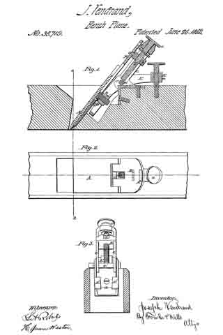
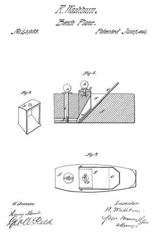
Be it known that I, GEORGE F. EVANS, of Norway, in the county of Oxford and State of Maine, have invented a new and useful or Improved Plane; and I do hereby declare the same to be fully described in the following specification, and represented in the accompanying drawings, of which —

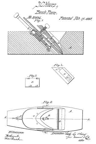
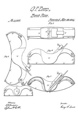
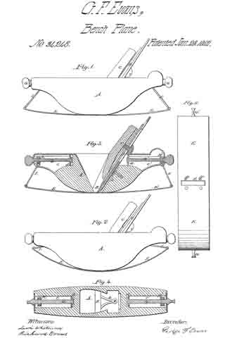
Figure 1 denotes a side elevation; Fig. 2, a longitudinal section of my said plane prepared to operate upon a curved surface having a great degree of curvature; Fig. 3, a side elevation of such plane as prepared to plane on a surface having the slightest curvature; Fig. 4, a horizontal section of the plane, taken through the adjusting-screws and traversing nuts. Fig. 5 is a bottom view of the plane.

The object I had in view in making my invention was to supply a want which has long existed, viz: an instrument which would plane or smoothen any circular concave surface evenly and exactly.

The nature of my invention consists in an improved plane so constructed that its bearing surface or face may be readily adjusted to conform to circular surfaces of different degrees of curvature, whereby such circular parts may be as easily and smoothly planed as a plane surface can be by the ordinary straight-faced plane.

In the drawings, A denotes the stock or body of the plane, the same having a throat or shaving passage B formed vertically through it. In the said passage or throat the plane iron or cutter is secured by means of a wedge C and a cap-plate D in the ordinary manner. Instead of forming the lower face of the stock A as a straight or plane surface,I cause the same to be curved upward in manner as shown in the drawings.

To the lower face of the stock I fasten a flat steel plate E by means of two screws a a, and a bifurcated bar b, whose lower ends extend through the said plate and are riveted thereto, while its other end is secured by means of a screw to the rear part of the throat-passage.

Within the two ends of the stock A and extending longitudinally therein I form two chambers c c’ for reception of two screws G G’ and two traversing nuts H H’, the said screws being supported in stationary bearings d d’, arranged in each end of each of the said chambers c c’. Each of the screws G carries a traversing nut H of a rectangular shape, the said nut being jointed or pivoted at its lower edge with a connecting-rod I, whose lower end is in turnconnected or jointed to the plate E’, the length of the connecting-rods being suoh as to allow the plate E, when the nuts H H’ are at their greatest point of outward extension, to assume or stand in or nearly in a horizontal plane. The screws G or G’ have no longitudinal movement, but are free to revolve on their axes, so as to cause the nuts H H’ to traverse the whole length of their chambers c c’.

A plane constructed in the above-described improved manner can be readily adapted or adjusted to plane or reduce any circular concave piece of wood by simply turning the two screws G G’ in the proper direction.

Having described my invention, I claim —

My improved plane, having its body A, its bearing-plate E, its screws G G’, traversing nuts H H’, and connecting-rods I I, constructed and arranged in relation to each other and so as to operate together, as set forth.

GEORGE F. EVANS.

Witnesses:
LEVI WHITMAN,
RICHARD EVANS.

No. 35,719 – Improvement In Planes (Joseph Vendrand) (1862)

[paiddownloads id=”96″]35719


UNITED STATES PATENT OFFICE.

_________________

JOSEPH VENDRAND, OF PARIS, FRANCE.

IMPROVEMENT IN PLANES.

_________________

Specification forming part of Letters Patent No. 35,719, dated June 24, 1862.

_________________

To all whom it may concern:

Be it known that I, JOSEPH VENDRAND, of Paris, in the Empire of France, have invented certain new and useful Improvements in Planes; and I do hereby declare that the following is a full and exact description thereof.

All persons accustomed to the use of hand-planes are acquainted with the difficulty of properly adjusting the plane-iron in the stock in such a manner as to give the perfect parallelism which must exist between the face of the plane and the edge of the iron, and to secure the perfect nicety of adjustment of the projection of the edge beyond the face of the plane, which is necessary for fine work.

The improvements which I have invented and for which I desire to obtain a patent obviate perfectly the inconveniences above stated.

They consist in the construction and arrangement of parts, hereinafter described, by which an additional regulation is attained, so as to preserve the parallel position of the cutting-edge with reference to the face of the plane, while it is raised or lowered by the adjusting-screw to adapt it to cut the proper thickness of shaving, and also in the construction and arrangement of parts for securing the plane-iron in position.

The regulator by which the plane iron is adjusted to the proper depth of cut, which is operated simply by the hand, does not sensibly complicate the plane, and it permits the regulation of the projection of the iron to the utmost nicety that may be desired.

For the purpose of facilitating the operation of the plane for persons who are not much habituated to its management, I in some cases cut away the wood of each of its sides in such a manner as to produce grooves sufficiently deep to permit it to be easily grasped when the workmen desires to raise the tool or to direct it to his fancy with greater ease.

The accompanying drawings will give a clear idea of the nature ofthe invention.

Figure 1 is a longitudinal vertical section of a plane constructed with my improvements. Fig. 2 is a plan of the same. Fig. 3 is a transverse vertical section showing the parts toward the rear end of the plane from the line 1 2, the plane-iron and cap being removed to give an unobstructed view of other parts.

The iron A is controlled by the tenon a, which is a part of the nut B, sliding on the support C, by means ofthe screw V, which is operated by the milled head v. The tenon a fits into a mortise, It, which is made transversely in the iron A and of sufficient length to allow the necessary lateral adjustment of the upper end of the iron to bring the edge parallel with the face of the plane.

The iron, regulated by means of the screw V, is retained in the position given it by the movable stirrup E, which oscillates on an axis, e’, in the fixed support C. For that purpose the stirrup or frame E is separated or divided in the lower part into two branches, upon which two parallel ears, E’, are formed, which ears take hold of the flange of the nut a’, Fig.
4, which binds the iron and cap together.

The stirrup E is operated to secure the plane-iron to its seat by means of screw e, which passes through the socket or eye E2, and rests at its lower end upon the head of a screw sunk in the top of the plane. By turning the screw e down upon this support the eye E2 is raised and the ears E’ conseqnently forced back so as to draw the plane-iron and cap down firmly against the wood, which supports them and retains them securely in position. In adjusting the iron it may be proper to slightly loosen the screw e to allow the iron to be moved with greater ease. The adjustment is then made by means of the screw V to any desired exactness. The first adjustment to be made, however, upon inserting the plane-iron is to get the edge perfectly parallel with the face of the plane, which the mode of connecting the plane-iron to the adjusting-screw by the elongated mortise and tenon on the nut in which the adjusting-screw works enables the operator to do satisfactorily. This adjustment once made, the plane-iron may be moved up and down without disturbing the parallelism of the edge with the face ofthe plane.

When it is desired to remove the plane-iron, the screw e should be turned back about three revolutions, which will give the necessary play between the ears E’ and the nut a’ to allow such removal.

The improvements which I have described may be applied with equal advantage to planes of every size and to planes for working rabbets, moldings, and cavettos.

I am aware that planes have been constructed in which the cutting-iron has been adjusted by raising and lowering it through the agency of a screw, without any means of lateral adjustment to secure perfect parallelism between the edge of the cutter and the face of the plane. I am also aware that a patent was granted to Thomas D. Worrall, August 4, 1857, in which a flange is represented attached to the plane iron, upon which flange a lever, hung upon an axis near the top of the stock and operated by a screw from the rear, is intended to operate to secure the cutter in position. The arrangement of parts is, however, different from that I have described, and involves objections in practical use which my invention avoids. The attachment of the flange adds expense and complication to the plane, While in my invention the nut which secures the cap to the cutter also furnishes the means of grasping and securing it in position. The arrangement of the screw for fastening the plane-iron back of the lever upon which it operates to secure said iron, as in Worrall’s plane, is also objectionable, because it involves complication of parts, and because it brings the head of the screw in the way of the right hand of the workman when operating the plane. These objections are avoided by my invention.

I claim–

1. The combination, with the plane-iron A, provided with mortises R, as described, of the adjusting-screw V, sliding block B, and tenon a, the said tenon and mortise being relatively so constructed as to allow the iron sufheient lateral play to permit the perfect adjustment ofthe edge parallel to the face of the plane, as set forth.

2. The combination of the nut a, which secures the cap to the cutting-iron, with the lever E and ears E’ E’, as and for the purpose set forth.

3. The arrangement of the lever E and screw e, as described — that is to say, in such a manner that the screw shall take its point of support upon the top of the plane and, extending up through the nut E2, terminate in a head for operating above the lever E, as set forth, instead of behind it, where it would be in the way of the operator.

In testimony whereof I have signed my name to this specification before two subscribing witnesses.

J. VENDRAND.

Witnesses:
E. RICHARD,
GEO. HUTTON.

No. 37,694 – Improvement In Bench Planes (Seth C. Howes) (1863)

[paiddownloads id=”97″]37694


UNITED STATES PATENT OFFICE.

_________________

SETH C. HOWES, OF SOUTH CHATHAM, MASSACHUSETTS.

IMPROVEMENT IN BENCH-PLANES.

_________________

Specification of Letters Patent No. 37,694, dated February 17, 1863.

_________________

To all whom it may concern:

Be it known that I, SETH C. HOWES, of South Chatham, in the county of Barnstable and State of Massachusetts, have invented a new and useful Improvement in Bench-Planes, such as are used by joiners and other artisans in wood; and I do hereby declare that the following is a full, clear, and exact description of the same, reference being had to the accompanying drawings, making part of this specification, in which —

Figure 1 is a vertical section of my invention, taken in the line x, x, Fig. 2. Fig. 2 is a plan or top view of the same. Figs. 3 and 4 are detached views of parts pertaining to the same.

Similar letters of reference indicate corresponding parts in the several figures.

This invention relates to an improvement in that class of planes which are commonly termed “bench-planes,” comprising the fore-plane, smoothing-plane, jack-plane, jointer, &c.

The invention consists in a novel and improved mode of adjusting the plane-iron to regulate the depth of the cut of the same, in connection with an adjustable cap, all being constructed and arranged in such a manner that the plane-iron may be “set” with the greatest facility and firmly retained in position by the adjustment simply of the cap to the plane-iron, after the latter is set, and the cap also rendered capable of being adjusted to compensate for the wear of the “sole” or face of the plane-stock.

To enable those skilled in the art to fully understand and construct my invention, I will proceed to describe it.

A represents the stock of the plane, which may be constructed of wood, as usual, and B is the throat or opening in the stock, in which the plane-iron C and cap D are fitted. The iron C is of the usual shape, and it has four holes made in its back surface, to receive a corresponding number of spurs, b, which are on the front side of a square nut, E, the latter being fitted in an inclined recess, c, in the stock, at the back part of the throat B.

F is a rod, the lower portion of which has a screw, d, cut on it. On this screw d the nut E is fitted. The rod F, just above the screw d, is fitted in a socket or bearing, G, in the upper part of the stock. The lower end of the rod F is fitted in a bearing, H. (See Fig. 1.)

D represents the cap, the lower end of which presses against the front side of the plane-iron G, when the plane is in condition for use. The cap D is provided with pins or trunnions e e — one at each side — and these pins or trunnions are fitted in bearings f f, which are of square or rectangular form, and fitted in oblong slots g g in metal plates J J, the latter being secured in an inclined position in the stock A — one at each side of the throat B — by means of screws a’. The bearings f at one side are notched or serrated, and the upper sides of the slots g are also serrated, so that the serrated edges of the bearings may engage therewith. (See Fig. 4.) By this arrangement the bearings are prevented from casually moving in their slots g. Through the upper part of the cap D a screw, K, passes, and this screw bears against the plane-iron C and keeps the spurs b of the nut E engaged with the holes in the plane-iron, and the plane-iron in close contact with the nut, as will be fully understood by referring to Fig. 1. In order to adjust or set the plane-iron C, the rod F is turned, the plane-iron being thereby raised and lowered, the screw K being turned so as to relieve the plane-iron C of its pressure as well as of the pressure of the lower end of the cap D. When the plane-iron is set, the screw K is turned so as to press the lower end of the cap D against the lower part of the plane-iron, and by this adjustment the pressure of the screw K keeps the plane-iron in contact with the nut E. The plane-iron, therefore, it will be seen, is firmly retained in position when the plane is in condition for use. In case the sole or face of the stock A becomes worn by use, or requires to be faced or planed off, the cap is elevated by removing the plates J J from the stock and placing the bearings f f rather higher in the slots g g, the serrated edges of the bearings and slots holding the bearings in proper position at any desired points in the slots.

Having thus described my invention, what I claim as new, and desire to secure by Letters Patent, is —

The rod F, having the screw d cut upon it, and provided with the nut E, with spurs b on its outer surface, to fit in holes in the plane-iron C, in combination with the cap D, provided with the screw K and trunniouse e the f f, which are placed in slotted plates J J , and retained therein at the desired point by the serrated edges of the bearings and the slots or a equivalent means, all arranged substantially as set forth.

SETH C. HOWES.

Witnesses:
JOHN G. DOANE,
FREEMAN E. CHASE.

No. 40,437 – Spokeshave (Melzer Tuell) (1863)

[paiddownloads id=”98″]40437


UNITED STATES PATENT OFFICE.

_________________

MELZER TUELL, OF PENN YAN, NEW YORK.

SPOKESHAVE.

_________________

Specification forming part of Letters Patent No. 40,437, dated October 27, 1863.

_________________

To all whom it may concern:

Be it known that I, MELZER TUELL, of Penn Yan, in the county of Yates and State of New York, have invented a new and useful Improvement in Spokeshaves; and I do hereby declare that the following is a full, clear, and exact description of the construction and operation of the same, reference being had to the annexed drawings, making a part of this specification, in which —

Figure 1 is a bird’s-eye view. Fig. 2 is of the under side. Fig. 3 isa transverse vertical section.

The letters of reference refer to the same parts in each figure.

A is the stock. It is made with an opening or passage for the chips or shavings to pass up through while using it, and it has a handle at each end. The stock is made so that the cutter B and gage C may be fastened to it, as hereinafter described. The center of the stock, center of the cutter, and center of the gage are in the same lines, or both sides of the center are alike, so that the instrument will cut when pushed from or pulled toward the operator, or either end may be taken in the right hand and the result the same. At the under side of the stock, and in the middle and near each end of the opening, is a place fitted to receive the cutter, so that it may be held by bolts or screws that pass through both stock and cutter. The cutter must be far enough below the surface of the stock to admit the regulator above the edges of the cutter. This is done by making projections upon which the knife is fitted for.

The handles are made in line with the cutter, but may be curved up or down, as desired.

At the under side of the stock is placed the adjustable gage C. It is made the width, outside, as the stock, with an opening through it as long as and a little wider than the cutter, so that it will surround the cutter. It is held to the stock by means of pivots F and F, that pass through the projections E and E at the under side of the stock, and through holes in the ends of the gage, as represented in Fig. 2; or the pivot may be made to enter holes made in the ends of the cutter. The gage must be made so as to be easily moved upon the pivots, so that either side of the gage may be raised above the edge of the cutter to admit the edges of the cutter to take the thickness of chip required, so that the more the gage rotates the thicker will be the chip. This motion of the gage is governed by the set-screws D and D. These screws are put through the sides of the stock, as represented in Figs. 1 and 3. By these screws the thickness of the chip is regulated. Wlien the screws are turned back-ward,the chip will be thicker, and when turned forward the regulator has less motion and consequently the cutter cuts a thinner chip.

I do not limit myself to any particular curve, (up or down,) but make them any curve to suit any kind of work, and when any curve of cutter is required the stock and gage must be made to correspond with it. The cutter is made with two opposite cutting-edges, with a hole at each end for bolts or screws that hold it to the stock. To use my invention, first find by trial the thickness of chip. If too thick or too thin, regulate by the screws D D, which is best performed by regulating one side at a time, and when both sides are regulated take one handle in each hand and place the under side of the instrument upon the work and either push it from or pull it toward you, which will cause the instrument to do the work required. This motion will cause the gage to raise to the screws D D one side at a time and allow the edge of the cutter to take hold of the work. Thus each edge of the cutter will take hold of the wood; but both edges will not cut at the same time, but the instrument willwork either way, as the grain of the wood requires.

What I claim, and desire to secure by Letters Patent, is —

1. The stock A and cutter B, when constructed and arranged as and for the purpose Set forth.

2. The adjustable gage C, when made and used as specified.

MELZER TUELL.

Witnesses:

I. SLOAN,
CHARLES KETCHUM.

No. 40,483 – Improvement In Planes For Beading And Molding (Seth C. Howes) (1863)

[paiddownloads id=”99″]40483


UNITED STATES PATENT OFFICE.

_________________

SETH C. HOWES, OF SOUTH CHATHAM, MASSACHUSETTS.

IMPROVEMENT IN PLANES FOR BEADING, MOLDING, &c.

_________________

Specification forming part of Letters Patent No. 40,483, dated November 3, 1863 ; antedated October 24, 1863.

_________________

To all whom it may concern:

Be it known that I, SETH C. HOWES, of South Chatham, in the county of Barnstable and State of Massachusetts, have invented a new and useful Improvement in Planes for Beading, Molding, &c., &c. ; and I do hereby declare that the following is a full, clear, and exact description of the same, reference being had to the accompanying drawings, making a part of this specification, in which —

Figure 1 is a vertical section of my invention, taken in the line x x, Fig. 2; Fig. 2, a plan or top view of the same 5 Fig. 3, a side view of the same; Fig. 4, a detached face view of the clamp which holds the plane iron in proper position.

Similar letters of reference indicate corresponding parts in the several figures.

This invention relates to an improvement in that class of planes used by joiners for forming beads and moldings, and also for forming rabbets, and which discharge the shavings at the side of the stock.

The object of the invention is to obtain a plane of the kind specified which will discharge the shavings freely and without the liability of choking or clogging in the throat, and one also which will admit of the iron being adjusted with the greatest facility to regulate the depth of cut and admit of the iron being firmly secured in the stock.

To enable those skilled in the art to fully understand and construct my invention, I will proceed to describe it.

A represents the stock of the plane, which is constructed of wood, and of the usual form, and B is the “iron,” the lower end or cutting-edge of which is made of a form corresponding to that of the bead, molding, or rabbet to be cut. This iron has a notch, a, made in its back surface, near its upper end, and into this notch a projection or spur, b, on a nut, C, is fitted, said nut being in an inclined recess or groove, c, in the stock. The nut C is on a screw, D, the upper part of which is iitted in a metal socket, F, placed in a recess in the upper part ofthe stock. The upper part of the plane-iron is fitted in the front part of the recess or groove c, while the lower part passes through a recess, F, which is open at its side, and forms what is commonly termed the throat, to admit of the shavings out by the iron to pass out from the stock. This throat is narrow at its lower end, as shown at d, and it widens very gradually for a short distance upward, and then suddenly expands or increases in width, with a rounded front, e, as shown clearly in Figs 1 and 3.

Within this enlarged part of the throat there is fitted a metal socket or guide, G, in which a clamp, H, works. This clamp is also constructed of metal, and may be described as being formed of a rectangular bar, having one side beveled, as shown at f (See Fig. 4.) The clamp is allowed to work freely in the socket or guide G, and it is moved or operated by a screw, I, which works in an internal screw-thread, g, in the clamp, as shown in Fig. 1, and is litted in a metal socket, J, placed in a recess in the upper part of the stock. The portions of the screws I and D, which are htted in the sockets E and J, are smooth, (see Fig. 1,) and the beveled surface f is placed outward.

From the above description it will be seen that by turning the screw-rod D, the iron may be raised and lowered according to the depth of cut or thickness of shaving required, as by turning said screw the nut C is moved, and with it the iron, and when the desired set of the iron is obtained, the latter is secured in position by pressing the clamp H against it, the latter result being attained by turning the screw I. The back part of the iron is pressed by the clamp H firmly against the back part of the throat F.

In using the implement the shavings will readily pass up the lower narrow part of the throat, and in passing into the enlarged part they will turn freely the rounded corner e, and, coming in contact with the hard, smooth metal surfaces of the inner side of the socket or guide G, and the beveled surface f of the clamp H, are discharged freely from the throat, and all choking and clogging of the latter avoided.

The ordinary throats of this class of planes are very liable to choke or clog with shavings, as they have a comparatively long narrow opening at their lower parts, and are not provided with any rnetal surfaces, which have a tendency to prevent the sticking or adhering of the shavings in the throat.

Having thus described my invention, I claim, as an improved article of manufacture —

A molding-plane provided with the adjusting-nut C, screw D, the holding-clamp H, screw J , and curved throat e, all constructed and operating together, as herein shown and described.

SETH C. HOWES.

Witnesses:
JOHN G. DOANE,
FREEMAN E. CHASE.

No. 41,258 – Improvements In Planes For Jointing Table Leaves (T.P. Granger) (1864)

[paiddownloads id=”100″]41258


UNITED STATES PATENT OFFICE.

_________________

T. P. GRANGER, OF PECATONICA, ILLINOIS, ASSIGNOR TO HIMSELF AND JOSIAH BEST.

IMPROVEMENT IN PLANES FOR JOINTING TABLE-LEAVES.

_________________

Specification forming part of Letters Patent No. 41,258, dated January 12, 1864.

_________________

To all whom it may concern:

Be it known that I, T. P. GRANGER, of Pecatonica, in the county of Winnebago and State of Illinois, have invented new and useful Improvements in Planes for Jointing Table-Leaves; and I do hereby declare that the following is a full and complete description of the construction and operation of the same, reference being had to the accompanying drawings, making part of this specification, in which —

Figure 1 is an end View of the first plane used in forming the bed part of the joint. Fig. 2 is a face view of the same plane. Fig. 3 is an edge view of the bed-leaf after the first plane has been used upon it; and Fig. 4 is an end view of the same. The plane, Figs. 1 and 2, is so formed, as shown at A, as to cut the “round” B on the bed-leaf.

The bed-leaf is first prepared by being jointed on the lower side and edge, the guide C working against the lower side, B’, Fig. 4. A stop, C’, on the opposite side of the plane, by coming in contact with the edge of the leaf B”, determines the depth to which the plane, cuts. Planes, Figs. 5 and 6, show an end and face view of the second plane to be used upon the bed. This is for cutting away B”, Fig. 4, which has been left by the first operation. The guide D works flat against the lower side of the leaf, the groove D’ forming a stop by coming in contact with B, Fig. 3. After the planes, Figs. 5 and 6, have been used the edge of the leaf presents the appearance shown in Figs. 7 and 8. I now use the planes shown in Figs. 17 and 18, for the purpose of cutting the round B to a sharper angle with the square portion of the leaf, as shown at a b in Figs. 19 and 20. This operation finishes the bed-leaf. The fall-leaf is first prepared for making the joint by being jointed upon the under side and upon the joint edge. I then apply the plane shown in Figs. 9 and 10, the guide E working against the under side of the leaf. The face F of the plane coming in contact with the square edge of the leaf F’, determines the depth to which the groove G is cut in the edge of the leaf; but as this plane does not cut the groove G quite deep enough to fit the round B on the bed-leaf. I apply the plane shown in Figs. 13 and 14. The face H coming in contact with the edge F’, determines the depth to which this plane cuts the groove, which is shown complete at c d in Figs.15 and 16. The table-butts are now set in the usual manner, and the leaf presents the structure and adjustment shown in Figs. 21 and 22. A table joint thus constructed presents this peculiar feature, that when the leaf is down, as in Fig. 22, the inner angle of the leaf comes in contact with the under edge of the bed, as at e, and thus raises the fall-leaf higher up on the bed-leaf, as shown at e’, thereby making a better and more durable joint.

What I claim as my improvement, and desire to secure by Letters Patent, is —

The herein-described series of planes for setting table-joints, the same being constructed and used in the manner and for the purpose herein set forth.

T. P. GRANGER.

Witnesses:
A. S. VAN DYKE,
A. J. THOMPSON.

No. 41,317 – Improvement In Planes (Eli Odell) (1864)

[paiddownloads id=”101″]41317


UNITED STATES PATENT OFFICE.

_________________

ELI ODELL, OF WINTERSET, IOWA.

IMPROVEMENT IN PLANES.

_________________

Specification forming part of Letters Patent No. 41,317, dated January 19, 1864.

_________________

To all whom it may concern:

Be it known that I, ELI ODELL, of Winterset, Madison county, and State of Iowa, have invented an Improvement on the Common Plane in two particulars, as hereinafter described, reference being had to the accompanying drawings, and to the letters of reference marked thereon.

The nature of my improvements are in the two following particulars: First, the thread of the plane is to be cut concave, instead of convex, as in the usual term, thus entirely preventing it from choking with shavings, as is customary with the common form; second, improvement is to prevent the enlargement of the throat of plane as the face wears away by use, which is done in the following manner: Cut out to the depth of one inch (more or less) the face of the plane from the throat to the iront end. Then cut a groove in the center of the plane from the front end to the throat on the under side. Then make a separate piece to form that part of the face of the plane cut out, and also to fit the groove accurately. The object of this piece on the face of the plane is to keep the throat of the plane small as the face wears away by use, and is done by cutting the shoulder at the throat of the plane and sliding the face-piece toward the bit, and is represented by the letter B. Thus, the throat may be regulated in size until the plane is worn out. Said face-piece is moved by and held by two screws, the one on the top, letter C, passing through the upper part of the plane and down into letter B into a nut that has play, that it can slide along in a mortise in letter B. The other, in the frontend, (represented by D,) connects with a nut in a mortise in the upper part of the plane, which nut hooks into letter B, which can slide either to open or shut the throat. In order to disconnect letter B (the face-piece) from the plane, unscrew letter C until letter B comes loose.

What I claim as new, and desire to secure by Letters Patent, is —

A plane, with the adjustable face-plate B, in combination with a concave throat, the whole constructed and operated substantially as described.

ELI ODELL.

Witnesses:
JNO. LEONARD,
A. D. NOSLER.

No. 41,983 – Improvement In Plane Stocks (George Franklin Evans) (1864)

[paiddownloads id=”102″]41893


UNITED STATES PATENT OFFICE.

_________________

GEORGE FRANKLIN EVANS, OF NORWAY, MAINE.

IMPROVEMENT IN PLANE-STOCKS.

_________________

Specification forming part of Letters Patent No. 41,983, dated March 22, 1864.

_________________

To all whom it may concern:

Be it known that I, GEORGE FRANKLIN EVANS, of Norway, in the county of Oxford and State of Maine, have made new and important Improvements in the Plane that was patented January 28, 1862; and I do hereby declare the same to be fully described in the following specification, and represented in the accompanying drawings, of which —

Figure 1 is a plan. Fig. 2 is a longitudinal elevation with the face-plate in a straight position. Fig. 3 is a longitudinal vertical section with the face-plate in a convex position. Fig. 4 is a longitudinal elevation with the face-plate in a concave position or reversed from that in Fig. 3. Fig. 5 is a longitudinal elevation of the rabbet and grooving plane with the face-plate in a straight position.

The nature of my improvement consists not only in the manner of making the stock, but in the combination of the arms which connect the ends ofthe spring face-plate to the stock, the same admitting the spring face-plate to be curved either ccnvexly or concavely on its outer surface. These planes are so constructed that they may be more readily adjusted to conform to concave and convex surfaces of diiferent degrees of curvature, whereby such circular parts may be as easily and smoothly planed, grooved, or rabbeted as a plane surface can be by the ordinary straight taced plane.

In the drawings, A is the stock or body of the plane, the same having a throat or shaving passage, B, formed vertically through it, (horizontally in the grooving-plane, Fig. 5.) In the said passage is the plane-iron, which is secured by the leverchip C and the thumb-screw D.

Instead of forming the lower face of the stock A as a straight plane, I cause the same to be curved upward and downward, in the manner as shown in the drawings. To the lower face of the stock I fasten on a flat steel plate by means of ten steel rivets, E E, on the lower part of the throat-passage — five rivets on the forward part and five rivets on the rear part of the throat-passage, as shown in Fig. 1.

Within the two ends of the stock A pass the connecting-rods F F in the form of a segment of a circle. The lower end of each connecting-rod has a hinge-joint, and is received by a socket or hollow pipe with solid ends, which pipe or socket is fastened to the ends of the steel plate G G by means of two steel rivets, I I. In each end of the stock A is a set-screw, H,which holds the connecting-rods F F in position, as shown in Figs. 2 and 4.

A plane constructed on the above-described improved manner can be readily adjusted to plane any circular, concave, or convex piece of wood; also to groove or rabbet the same by simply bending the plate G to the desired position and securing it by means of the connecting-rods F F and the set-screws J J.

From the above and by inspection of the drawings it will be perceived that my improved plane has its stock formed with two curved ends or projections extending from the part B, which hold the plane-iron, and so adapted to receive the curved arms F F as to allow them to play or move in curved paths both toward and away Ironi the said part B. Now, this mode of making the plane-stock not only enables the spring face-plate to be bent either into a convex or concave form, but it renders the curved ends or projections very convenient as handles by which the plane may be held and operated. Furthermore, they not only give to the connections F F a long range of motion, but keep their upper ends always within the stock when the face-plate is convex on its outer surface, there being no projection of the connections F F above the top surface of the plane-stock when the G is bent to its extreme position, as shown in Fig. 3.

What, therefore, I claim as my invention or improvement in the plane made with the spring face-plate is —

The construction of the connecting-rods F F and their receiving parts of the stock, curved substantially in the manner and so as to operate together as specified.

GEORGE FRANKLIN EVANS.

Witnesses:
HENRY UPTON,
C. C. SANDERSON.

No. 42,585 – Improvement In Grooving Or Panel Plows (William S. Loughborough) (1864)

[paiddownloads id=”103″]42585


UNITED STATES PATENT OFFICE.

_________________

WILLIAM S. LOUGHBOROUGH, OF ROCHESTER, NEW YORK.

IMPROVEMENT IN GROOVING OR PANEL PLOWS.

_________________

Specification forming parts of Letters Patent No. 42,585, dated May 3, 1864.

_________________

To all whom it may concern:

Be it known that I, WM. S. LOUGHBOROUGH, of Rochester, in the county of Monroe and State of New York, have invented a new and useful Panel-Plow or Grooving-Plane; and I do hereby declare that the following is a full, clear, and exact description thereof, reference being had to the accompanying drawings, making a part of this specilication, in which —

Figure 1 is an elevation of the left side of the plane. Fig. 2 is an elevation of the right side. Fig. 3 is an end view of the fence B detached, showing the front arm, C.

Similar letters of reference indicate corresponding parts in the several figures.

The nature of my invention consists, mainly, in the peculiar construction of the stock of panel-plows or other grooving-planes ; also, in a novel and efficient means for securing the adjustment of the fence by simply turning one screw, and in an improved manner of securing the bits in this class of planes.

A in the drawings represents the skeleton stock; B, the fence; C and C’, the arms; D, the thumb-screw ibr fastening the bit; E, the screw for fastening the arms of the fence; a, the screw for holding the stop S ; G, the bit ; b and b’, the clamping-bars, and w the wedge, which is operated upon by the screw E, by which it is driven down between the end of the bars b and b’, causing them to clamp firmly against the arms of the fence and to hold it securely in position. The wedge should be made sufficiently obtuse to cause it to recede from between the bars whenever relieved by the screw.

The body or stock A of the plane is made, as seen in the drawings, with an enlargement, d, running diagonally across and projecting equally on each side. Within this enlargement is formed a mortise, through which the bit G is placed. This mortise should be five-eighths to three-fourths of an inch wide, and it is recessed on the front or upper side, as indicated by the dotted lines, which is done by enlarging the core. Said core should also have a projection on the right side, near the lower end, to form the opening under the clasp f for the bar b1’ to pass through. The clasp g is formed by “coping out” in molding, part ofthe stop being removed, as seen in Fig. 1, to show the recess. The oval-shaped recess in which the wedge w is placed is formed in the same manner, and is made deep enough to receive the upper end of the bars b and b’ and the thickness of the flange i. The clasp g is extended over the upper rib of the arm G, and a similar bearing is provided over C’ by the projection a. These bearings prevent the arms from “tilting” when released by the screw E. The projections J should be long enough to prevent any cramping of the arms when the fence is being moved either way, and also to secure its parallel movement, it being cast or otherwise rigidly fixed to the arms.

The stop S is secured between the diagonal ribs r by the screw a, which may have a milled head, if desired. The ribs r are cast with the stock, and they receive all the diagonal strain coming upon the stop, thereby relieving the screw a from all lateral strain. The stock A is thickened by the button u (seen in Fig. 2) to increase the threaded bearing ofthe screw a.

The arch N of the throatway may be formed on either side ofthe stock, but the right hand side is probably preferable.

The bits G are made of uniform thickness from end to end, and are provided, the same as other plow-bits, with a central groove in the back side, which rides the front end of the rear plate, P’, and they are so fitted in the mortise as to have a bearing at t before they strike the rest at v, against which they are forced by the screw D and firmly held. This manner of fitting the bits, always effecting a perfect bearing of the bit at t, whether a wide or narrow one is used, insures the discharge of the shavings.

The plate p projects each side across the stock so as to form the seat for the handle H centrally behind the bit. The handle is held against the side plate, lt, by the screw s, and the rear end is firmly held in position by a screw through the base plate p at y.

The fence B may be removed at any time without deranging the clamping devices, the flange i of the wedge to preventing the end of the bars b and b’ from falling out. There is a shoulder on the back side of b’ at e, Fig. 2, which strikes against the case of the bit-mortise, and thus prevents the bar from dropping away from the flange i, and b is kept in position longitudinally by the point c resting against the stock.

If desired, the arms G and C’ may be made separate from the fence B and attached thereto by screws or otherwise; but I prefer to cast them together, as shown in the drawings.

Among the many advantages afforded by making these tools of metal instead of wood are the following: They are much less cumber-some, are more durable, the parts are much more readily and perfectly adjusted, they work better and easier, because they never choke or clog with the shavings, and they can be sold for less than one-half the cost of wooden planes of the same variety.

The plates P and P’ are cast on the stock A, thereby avoiding the labor and expense of fitting and attaching them by screws or other-wise.

What I claim as my invention, and desire to secure by Letters Patent, is —

1. The above-described panel plow or plane, when constructed, arranged, and combined in the manner and for the purposes specified, as a new article of manufacture.

2. Securing the gage of the fence B at any desired point by operating a single screw, E, substantially in the manner specified.

WM. S. LOUGHBOROUGH.

Witnesses:
A. C. DICKINSON,
A. H. BILLINGS.

No. 43,053 – Improvement In Bench Planes (Richard Washburn) (1864)

[paiddownloads id=”104″]43053


UNITED STATES PATENT OFFICE.

_________________

RICHARD WASHBURN, OF RAMAPO, NEW YORK.

IMPROVEMENT IN BENCH-PLANES.

_________________

Specification forming part of Letters Patent No. 43,053, dated June 7, 1864.

_________________

To all whom it may concern:

Be it known that I, RICHARD WASHBURN, of Ramapo, in the county of Rockland and State of New York, have invented a new and useful lmprovement in Bench-Planes; and I do hereby declare that the following is a full, clear, and exact description of the same, reference being had to the accompanying drawings, forming apart of this specification, in which —

Figure 1 is a longitudinal vertical section of my invention. Fig. 2 is a plan or top view of the same. Fig. 3 is a detached perspective view of the slotted wedge which I use to secure the plane-iron.

Similar letters of reference indicate corresponding parts in the several figures.

This invention consists in the employment or use of a slotted wedge inserted in suitable guide-grooves in the front side of the throat of a plane, and adjustable by means of a set-screw, in combination with the plane-iron in such a manner, that by means of said slotted wedge and set-screw the plane iron can be firmly secured in the desired position, and by the point of the wedge the shavings are thrown oif from the cutting-edge of the iron and caused to pass up through the throat of the plane with ease and facility, and the use of a double iron can be dispensed with.

A represents the body of my plane, which is made of wood or any other suitable material, and provided with a throat, B, through which the plane iron C passes in the usual manner.
The plane-iron is secured in the throat by means of a slotted wedge, D, a detached perspective view of which is shown in Fig. 3. This wedge is guided in grooves a in the front side of the threat, and it is secured in its place by means of a set-screw, b, which passes freely through its top and screws into a nut fastened in the upper surface of the body A of the plane. The lower inclined surface, c, of the slotted wedge fits nicely on the upper surface of plane-iron, as clearly shown in Fig. 1, and its front edge is chamfered off in the opposite direction to that of the plane-iron, so that the shavings are thrown off from said cutting-edge, and that the inclined plate c of the slotted wedge takes the place of the ordinary double iron. By releasing the set-screw b the plane-iron can be easily adjusted up or down without the use of the hammer, and by tightening said set-screws the slotted wedge is firmly pressed down on the plane-iron and the latter is securely held in the required position. The sole of the plane is protected by a plate, E, secured to the front edge of the same by means of set screw d. This screw passes through an oblong hole, e, in the body of the plane, so that the plate E can be easily adjusted backward or forward and that by these means the mouth of the plane can be enlarged or diminished at pleasure. The plate E therefore serves the double purpose of protecting the sole of the plane and of making its mouth adjustable.

The improvements herein described are applicable to planes of every description, and it is obvious that the slotted wedge can be used independent of the adjustable plate E, or in combination with the same, as may be desired.

What I claim as new, and desire to secure by Letters Patent, is —

The slotted wedge D, secured in the throat of a plane, A, by means of a set-screw, b, and operating in combination with the same and with the plane-iron C, substantially in the manner and for the purpose specified.

RICHARD WASHBURN.

Witnesses:
DANIEL COOPER,
JAMES SUFFERN.

No. 43,360 – Improvement In Bench Planes (Stephen Williams) (1864)

[paiddownloads id=”105″]43360


UNITED STATES PATENT OFFICE.

_________________

STEPHEN WILLIAMS, OF PHILADELPHIA, PENNSYLVANIA.

IMPROVEMENT IN BENCH-PLANES.

_________________

Specification forming part of Letters Patent No. 43,360, dated June 28, 1864.

_________________

To all whom it may concern:

Be it known that I, STEPHEN WILLIAMS, of Philadelphia, in the county of Philadelphia and State of Pennsylvania, have invented a new and useful Improvement in Smoothing-Planes; and I do hereby declare that the following is a full, clear, and exact description thereof, which will enable others skilled in the art to make and use the same, reference being had to the accompanying drawings, making a part of this specification, in which —

Figure 1 is a side sectional elevation of my invention. Fig. 2 is a. plan view of the same.

Similar letters of reference indicate like parts.

I denominate my improvement the “universal smoothing-plane,” because it belongs to that variety of planes in which the face is made changeable, so that it may be conveniently adapted to the planing of curved as well as straight surfaces.

By the use of my improvement surfaces that are convex, concave, or straight may be easily worked, the thee of the tool being readily changed from one form to another to suit the surface to which it is to be applied.

A is a hollow box, of the exterior form shown, made, in one or more pieces, of iron or other materials, receiving the usual wedge, B, and plane iron C, which passes obliquely through the box A, a nipple, a, at its front end to receive the blow of the hammer during adjustment. The remaining body of the plane is composed of movable sections or blocks D, filted together, some of them, D’, made to conform at their upper ends to the shape of the box A, against which said ends press, as shown. The blocks or sections D D’ and the box A are bound together by an exterior hoop or band, E, of metal, which incloses them. The end piece, b,.of the band E is made sufficiently thick at its middle to have formed in it a screw-nut, through which a binding-screw, F, passes to press against the outer section or block, D, as shown. By turning the screw F the blocks or sections D D’ and box A will all be firmly bound or pressed together, and, as their lower ends constitute the surface of the plane, it is only necessary, in order to change the form of the face of the plane, to vary the position of the sections and box in respect to each other and then bind them by the screw F. Upon each alternate surface of the sections D D’ and box A there is a tongue and groove, c, d, which prevents lateral displacement of the sections, but allows of vertical adjustment. Upon the exterior of box A there are projecting tongues or ledges e e, between which the band E passes. These ledges prevent the displacement of the band E. The lower extremities of the sections D D’ and box A are made slightly rounded, so as to afford greater facility in moving the plane, prevent the edges of the sections from catching on the surface of the work, &c.

The black lines in Fig. 1 show the plane as adjusted to plane a concave surface. The red lines show the position of the parts when adjusted to plane a flat surface, and the blue lines show the adjustment for a convex surface.

I do not confine myself to the precise form of parts herein shown, as that may be varied according to the skill of the maker; but,

Having thus described my invention, I claim as new and desire to secure by Letters Patent —

1. The construction of the body ofthe plane of movable blocks or sections, substantially in the manner and for the purpose herein shown and described.

2. The combination of the movable sections D D’, independent plane bit-holder A, inclosing-band E, and screw F, all arranged and employed as described.

STEPHEN WILLIAMS.

Witnesses:
HENRY MCNEILL,
HENRY BENJAMIN.

No. 46,614 – Improvement In Bench Planes (Wing H. Taber) (1865)

[paiddownloads id=”106″]46614


UNITED STATES PATENT OFFICE.

_________________

WING H. TABER, OF LOWELL, MASSACHUSETTS, ASSIGNEE TO HIMSELF AND THOMAS H. ABBOTT, OF SAME PLACE.

IMPROVEMENT lN BENCH-PLANES.

_________________

Specification forming part of Letters Patent No. 46,614, dated February 28, 1865.

_________________

To all whom it may concern:

Be it known that I, WING H. TABER, of Lowell, in the county of Middlesex and State of Massachusetts, have invented a new and useful Improvement in Bench-Planes; and I do hereby declare the same to be fully described in the following specification and represented in the accompanying drawings, of which —

Figure 1 is a top view, Fig. 2 a side elevation, and Fig. 3 a longitudinal section, of a bench-plane provided with my invention. Flg. 4 is a top view of the furcated lever of the mechanism for fastening the plane-iron in place in the stock and on the adjustable bed. Fig. 5 is a front view of the said adjustable bed.

The nature of my invention or improvement consists in the combination as well as in the arrangement of an adjustable bed, and a mechanism, as hereinafter described, for fastening the plane iron in place in the stock and on the said bed, the parts of the said combination being arranged as hereinafter described, and the object or purpose of such invention being to enable the slant or inclination of the plane-iron to be varied in order to vary the width or size of the shaving-mouth at the cutting edge of the plane iron, and thus adapt the plane to the cutting of either thick or thin shavings from a piece of wood or article while being planed.

In the drawings, A denotes the plane-stock, provided with a throat, a, and a plane-iron, B, the latter having a cap iron or plate, C.

The plane iron rests on the lower part, b, of the throat a, and also on an adjustable bearing or bed, G, which is formed as shown in Figs. 3 and 5, screws into the stock, and is arranged in an inclined position, as exhibited in Fig. 3.

By taking hold of the head c of the bed or bearing G, and revolving the bearing, we can either screw it more of less into the stock, so as to vary the distance of the top of the head from the upper surface of the stock.

In advance of the bearing G there is a screw, D, which goes through the plane-iron and its cap-iron, and is screwed into the stock. A forked lever, E, clasps the shank of the screw D, and directly underneath the head d thereof, and has a screw, F, screwed through it and against the cap-iron G, the lower end of the said lever E being in contact with the cap-iron.

The adjustable fulcrum-screw D, the furcated lever E, and the screw F, constitute the mechanism for fastening the plane-iron in the stock or in the latter and to the bearing G. This fastening mechanism I do not claim as my invention by itself, or irrespective of the adjustable bearing G.

By the use of the said fastening mechanism no wedge is required to hold the plane in the stock. Consequently there will be no danger of splitting the stock, such as is incident to the wedge. The adjustable bearing G enables the shaving-mouth to be increased or diminished, as circumstances may require, and is also advantageous in other respects.

I lay no claim to the invention ofthe mechanism as above described for fastening the plane iron in the stock, such mechanism consisting of the screw D, the lever E, and the screw F, arranged with respect to the plane-stock and the plane iron or irons as described. Nor do I claim an adjustable bed as combined with stationary supports of the plane-iron, and constituting with them a means of confining the said plane-iron in its place in the stock, the same being as shown in Asahel G. Batchelder’s application for a patent filed in United States Patent Office on or about the 3d day of July, A. D. 1857, and subsequently rejected. My invention not only differs from those above cited as well in the structure as in the arrangement of its parts, but possesses one or more advantages not incident to them. In other words, while it retains all those of the fastening mechanism above mentioned, it has another which results from the adjustable bed not being required to be revolved in order to effect the fastening of the iron in the stock to be varied, such angle being for all practical purposes constant in the said Batchelder’s plane. I thus have the double advantage of not only varying the angle of inclination of the plane-iron, but of being capable of so springing the iron as to vary the breadth of the shaving-mouth of the throat as circumstances may require.

I claim —

1. The combination of the adjustable bed or bearing G, the screws F and D, and the lever E, the whole being arranged with respect to the plane-iron and the stock substantially as specifed.

2. The arrangement of the adjustable bed G, with the fulcrum-screw D, the lever E, the screw F, the plane-iron B, and its bearing b, arranged at the lower part of the throat a, as described.

WING H. TABER.

Witnesses:
J. N. MARSHALL,
JOEL A. ABBOTT.

No. 50,378 – Improvement In Bench Planes (George Müllear) (1865)

[paiddownloads id=”107″]50378


UNITED STATES PATENT OFFICE.

_________________

GEORGE MÜLLEAR, OF SAN FRANCISCO, CALIFORNIA.

IMPROVEMENT IN BENCH-PLANES.

_________________

Specification forming part of Letters Patent No. 50,378, dated October 10, 1865.

_________________

To all whom it may concern:

Be it known that I, GEORGE MÜLLEAR, of the city and county of San Francisco, and State of California, have invented certain new and useful Improvements in Carpenters’ Planes; and I do hereby declare that the following description and accompanying drawings are sufficient to enable any person skilled in the art or science to which it most nearly appertains to make and use my said invention or improvements without further invention or experiment.

The nature of my invention and improvement in planes consists in clamping the cutting-bit and turning the shaving cut by means of a metal cap drawn against the bit by a screw in the rear cf the plane-stock, and in making the clamping-cap adjustable horizontally by means of brackets, grooves, and adjusting-screws.

In the accompanying drawings, Figure I is an elevation of a plane with my improvements. Fig. 2 is a plan or top view. Fig. 3 is a section of the plane cut perpendicularly length-wise. Fig. 4 shows some of the parts enlarged and separate from the stock.

In these drawings, A is the plane-stock, B the handle, and C the cutting-bit, all of which are made in the form in common use by mechanics.

A mortise is made entirely through the stock horizontally for the traversing block M, which is fitted to traverse in it and moved by the screw I, which extends back through the rear of the stock and is provided with a collar, K, and there is a pin, L, through the stock behind the collar to prevent the screw from corning out when it is turned to traverse the block M. This block M is provided with two arms, R, which extend forward each side of the bit C and are perforated for screws which screw through the arms into the block N, which is properly the front part of the block M, as they are both traversed together by the screw I. The block N has two perpendicular grooves, P, for the flanges S of the brackets O on the cap H to traversein when the cap H is raised by the screw F or drawn down by the screws G G, which pass through the cap and screw into the block N, the screw F screwing through the cap onto the block N, and the screws G G passing through the cap and screwing into the block N, so that by turning the screws the cap may be adjusted higher or lower on the bit. The cap H is made in the form shown in Figs. 3 and 4, and bent so that both ends bear or press upon the bit C to clamp it in the stock and hold it in its place while the plane is used.

The head E of the screw I fits against the end ofthe stock A, so that by turning the screw I the blocks M and N, with the cap H, are drawn back toward the rear of the plane and the cap H presses upon the bit C and clamps it fast and holds it in position upon its bed in the stock while the plane is used; and the loweredge ofthe cap H may be adjusted higher or lower on the bit by turning the screws F and G so as to turn the shavings cut by the bit more or less short as they are cut. There is a brass plate, D, fitted into each side cf the plane and fastened by screws to cover the mortise occupied by the block M in the stock.

I contemplate that the traversing blocks M and N may both be made in one piece of malIeable iron, if preferred that way.

Having described my improvements, I claim —

I. The screw I, traversing blocks M and N, and cap H, for clamping and holding the bit and turning the shaving cut, substantially as described, whether the cap is made adjustable horizontally or otherwise.

2. Making the cap H adjustable higher or lower onthe cutting-bit by means of the brackets O, grooves P, and screws F and G G.

GEORGE MÜLLEAR.

Witnesses:
C. W. M. SMITH,
H. SAKEMAN.

No. 50,530 – Improvement In Bench Planes (Lyman C. Bliss) (1865)

[paiddownloads id=”108″]50530


UNITED STATES PATENT OFFICE.

_________________

LYMAN C. BLISS, OF RICHMOND, INDIANA, ASSIGNOR. TO LYMAN C. BLISS AND JOHN GRIFFITH.

IMPROVEMENT IN BENCH-PLANES.

_________________

Specification forming part of Letters Patent No. 50,530, dated October 17, 1865.

_________________

To all whom it may concern:

Be it known that I, LYMAN C. BLISS, of Richmond, in the county of Wayne and State of Indiana,have made new and useful Improvements in Bench-Planes; and I do hereby declare the following to be a full, clear, and exact description of the nature, construction, and operation of the same, sufficient to enable one skilled in the art to which it appertains to construct and use the same, reference being had to the accompanying drawings, which are made part of this specification, and in which —

Figure 1 is a View of the under side or face of the plane. Fig. 2 is a longitudinal vertical section on the line x x, Figs. 1 and 3. Fig. 3 is a transverse vertical section on the line y y, Figs. 1 and 2.

The same letters refer to corresponding parts in the different figures.

The invention consists in the adaptation to and arrangement in the tool of the jointer and slat-cutting plane.

A is the stock ofthe plane; and B,a strip which is fastened to the face of the plane, acting as a guide and separating the bits., The side C of the plane is occupied by the jointing-bit D, of ordinary construction, and the other side of the plane is faced with plates E and F, the former of which passes from the hind end of the plane to the back edge of the bit G, while the other, starting from the forward end of the plane, is partially overlapped by the oblique edge of the plane-bit G. The bit G is secured by means of a bolt, H, which passes through the slot in the rear edge of the bit and also through an orifice in the plate F, which on its rear edge is divided. The portion f of the plate, or that immediately over the longitudinal channel I in the face of the plane-stock, is cut diagonally, so as to present a yielding edge parallel with the cutting-edge of the bit, which overlaps it.

The operation is as follows: The jointing-bit D being first brought into action, the board from which the strip, splint, or slat is to be cut is straightened, when the plane is shifted so as to bring the other side into action, the sliver cut by the bit G pressing back the tongue f of the plate F, and passing out by the way of the channel I, to be discharged at the rear end ofthe plane. The splint or slat being separated from the edge of the board by the draw-cut of the bit G, leaves the said splint smoother and without cracks.

Having described my invention, what I claim therein as new, and desire to secure by Letters Patent, is —

As an article of manufacture, a bench-plane constructed, as described, with a jointing-bit and a draw-cut splint-cutting bit on the opposite sides of the dividing-strip on the face of the plane.

LYMAN O. BLISS.

Witnesses :
JOHN FINLEY,
THOS. A. DUGDALE.

No. 50,947 – Improvement In Splint Planes (Harrison Ogborn) (1865)

[paiddownloads id=”109″]13957


UNITED STATES PATENT OFFICE.

_________________

HARRISON OGBORN, OF RICHMOND, INDIANA.

IMPROVEMENT IN SPLINT-PLANES.

_________________

Specification forming part of Letters Patent No. 50,947, dated November 14, 1865.

_________________

To all whom it may concern:

Be it known that I, HARRISON OGBORN, of Richmond, in the county of Wayne and State of Indiana, have invented certain new and useful Improvements in Planes for Cutting Blind-Slats, Splints for Baskets, and other similar work; and I do hereby declare that the following is a full, clear, and exact description of the construction and operation of the same, reference being had to the annexed drawings, made a part of this specidcation, and the letters of reference thereon, the same letters referring to identical parts.

Figure 1 is a side view of the plane when arranged for use as a jack-plane, showing the bottom of the plane used for cutting slats, &c.
Fig. 2 is a longitudinal vertical section of the plane through the line y y, Fig. 4. Fig. 3 is a like section through the line x x, Fig. 4. Fig. 4 is a transverse section of the stock. Fig. 5 is a view of the knife employed for splitting the slats or splints. Fig. 6 is a view of a knife for splitting the slats with beveled edges. Fig. 7 shows the adjustable plate for determining the cut and removing splinters that wedge in the plane. Fig. 8 is a sectional view of the knife or bit used on the splint-plane. Fig. 9 is a top view of the same.

The stock of the plane A is arranged for two bits, and having two faces. One of these is an ordinary jack-plane, as shown in Figs. 1 and 2.

The handle B is adjustable, and may be made to stand perpendicularly to either of the plane-faces. It turns upon a rod, M, and, swinging in a notched recess in the corner of the stock, is held perpendicularly to either face by an ordinary window-catch, of which there are two shown, Figs. 2 and 3, G G’.

On the bottom of the face of the splint-plane are shown two adjustable guides, one square, the other beveled. One of these, according to the character of the work, is used on the left-hand side of the plane, held in place by screws with oblong heads working in slots in the ends of the guides, as shown in Fig. 1.

D is the knife or bit ofthe splint-plane, held in place by the same kind of screws working in slots, so as to allow the adjustment of the knife by the aid of the set-screws N N.

E shows the bit of the jack-plane, of ordinary construction, and arranged in the usual manner.

K is an adjustable plate, held by similar screws on the face, allowing its adjustment to the knife as they are worn away in use, to which is attached the set-screw passing through the stock and working in a collar on the upper surface of the plane. This arrangement makes it easy to withdraw the plate in case a splinter should wedge in the space between the plate and knife.

The knives H I, one straight, the other bent for cutting beveled edges, work as shown in Figs. 3 and 4. The knives are held in place by the wedge L, and the points protrude through narrow slots in the plate K. (Shown in Fig. 1.) The bent knife its the beveled point of the wedge L. When the straight knife is used the wedge goes on the right of it, but on the left side of the bent knife. There are one or more of these knives used, according to the number of slats intended to be cut from the board. The bent knife is used with the beveled guide.

In operating with this plane, the boards, being dressed, are cut into narrow strips of the proper width on their edges by the knife H, or so that the slats shall have beveled edges, by the knife I. The splints are cut by the knife or bit D passing between the plate K and the bit D. Rising over D, they are bent in a contrary direction, and passing out under the lower surface of the plane they are flattened and delivered free from curves or tendency to twist.

Having thus fully explained the character and operation of my improvements, what I claim as my invention, and seek to secure by Letters Patent, is —

1. The arrangement, in a splint-plane, of the plate K, bit D, and one or more splitting-knives, and guide C, all constructed and combined substantially as and for the purpose set forth.

2. The arrangement, in a splint-plane, of the piate K, bit D, beveled guide C and one or more bent knives, I, all constructed and combined substantially as and for the purposes set forth.

3. The combination of the plane-stock A and adjustable handle B, so constructed with the rod M and springs G and G’ as to be capable of being arranged perpendicularly to the two faces of the plane, substantially as described. In testimony whereof I have signed my name to this specifcation in the presence of two subscribing witnesses.

HARRISON OGBORN

Witnesses:
R. MASON, BEN FIELD.

No. 51,153 – Improvement In Splint Planes (James Dempsey) (1865)

[paiddownloads id=”110″]51153


UNITED STATES PATENT OFFICE.

_________________

JAMES DEMPSEY, OF RICHMOND, INDIANA.

IMPROVEMENT IN SPLINT-PLANES.

_________________

Specification forming part of Letters Patent No. 51,153, dated November 28, 1865.

_________________

To all whom it may concern:

Be it known that I, JAMES DEMPSEY, of Richmond, in the county of Wayne and State of Indiana, have invented certain new and useful Improvements in Planes for Cutting Slats for Window-Shades or other Thin Splints of Wood.

The object of my invention is to construct a splint-plane that shall be as readily adjustable as the ordinary hand-plane, and have such a channel for the splint when out as that it shall not be broken by being thrown abruptly upward over the knife. In other planes either the splint is liable to be broken or the knife placed horizontally is ditiicult of adjustment. Another object is to provide that the splint when cut shall be perfectly smooth and fit for use as it comes from the plane. Both of these objects are, I believe, accomplished by my im-provements.

To enable others skilled in the art to make and use my invention, I will describe its construction and operation, reference being had to the annexed drawings, making a part of this specification, and the lettering thereon.

In the different plans the same letters refer to identical parts.

Figure 1 is an elevation showing the half of the plane when divided into two parts, on the line x x, Fig. 3, where the plane as constructed is divided. Fig. 2 is a longitudinal section on the line x x, Fig. 3. Fig. 3 is a transverse section upon the line y y, Fig. 4. Fig. 4 is a plan of the plane, showing the bottom part, the guide being represented as cut away in part. Fig. 5 is a plan showing the construction of the bit. Fig. 6 is a plan showing the construction of the spring in the bottom of the plane.

The stock is made in two parts, A and B, of wood, joined by the dowel-pins L L and by screws.

C is the bit, of which about two inches of the lower end is nearly horizontal, but depressed at the point sutliciently to give the cutting-edge the requisite draft into the wood. It is bent at N, rising and passing transversely through the stock. It is adjusted by the set-screw H, and held firmly in place by the wedge M and clamps E E. These clamps catch upon the bit below and hold it firmly by stress of the nuts E’ E’ upon their upper ends. This bit is constructed with the rectangular slot G, which opens from the angle and extends upward about three inches, and having a width of about seven-eighths (7/8) of an inch. Over this slot the spring G is placed, bent upward and having the upper extremity, near O, turned slightly down, so as to hold firmly to the splint as it passes, and yet guide it through the slot at O. Upon the bottom of the plane, attached by a set-screw working in the slot F, is the spring D, the tongue extending above the bit and forming a guide for the splints as cut. On the bottom of the side B of the stock is fastened a guide, P, made adjustable by the set-screws and slots K.

On the under side ofthe wedge M, at its lower extremity, is cut a groove, of the width of the slot in the bit C, and terminating a little above the point ofthe spring G. Through this groove passes the splint.

In operating with the plane the guide p is set at one-half the width of the splint to be cut from the line x x. The bit C and spring D being adjusted by the set-screws I and H to cut splints of the required thickness, the bit C is held firmly in place by the wedge M and clamps E. The splint, being cut by the sharp point of the bit, rises above it, passing under the tongue of the spring upward through the groove in the under side of the wedge M, over the spring G. It passes through the bit C at O, and is carried through the stock in the groove D, passing out behind the plane unbroken and highly polished by the combined action of the cutter-bit and spring.

Having fully explained my mode of constructing and operating splint-planes, what I claim as my invention, and seek to secure by Letters Patent, is —

1. Constructing the bit C of a splint-plane with the slot and spring, substantially as described.

2. The arrangement of the spring D, clamps E, wedge M, stock A B, with the bit C, all of them constructed and combined substantially as and for the purpose described.

In testimony whereof I have signed my name to this specification in the presence of two subscribing witnesses.

JAMES DEMPSEY.

Witnesses:
R. MASON,
JOHN S. HOLLINGSHEAD.

No. 51,339 – Improvement In Spokeshaves (Silas S. Mowry And Albert G. Bates) (1865)

No. 51,339 – Improvement In Spokeshaves (Silas S. Mowry And Albert G. Bates) (1865)

[paiddownloads id=”111″]51339


UNITED STATES PATENT OFFICE.

_________________

SILAS S. MOWRY AND ALBERT G. BATES, OF PROVIDENCE, RHODE ISLAND.

IMPROVEMENT IN SPOKESHAVES.

_________________

Specification forming part of Letters Patent No. 51,339, dated December 5, 1865.

_________________

To all whom it may concern:

Be it known that we, SILAS S. MOWRY and ALBERT G. BATES, both of the city and county of Providence, in the State of Rhode Island, have invented a new and useful Improveinent in Spokeshavers; and we do hereby declare that the following specification, taken in connection with the drawings, making a part of the same, is a full, clear, and exact description thereof.

Figure 1 is a perspective view. Fig. 2 is a transverse section.

Our improvement has reference to a means for readily adjusting or removing the cutter, so that without loss of time the same can be removed to be sharpened, and be readjusted in place, While at the same time the advantage is secured of being able to make use of the plane-iron so long as there is enough of it left to be held in the stock.

In the accompanying drawings, A, Fig. 1, is the stock of the shaver, constructed with handles B B at the sides in the usual way. It is provided with a stationary iron, G, held by the screws a,a, passing through slots in the iron, so as to admit of adjustment for a finer or coarser cut of the knife, as desired, and thereby give all the advantages of the double plane-iron.

D is the knife or cutter, which is placed at the proper angle in the stock, as determined by the height of the rear portion, b, against which it bears.

The knife is held firmly in the desired position with reference to the stationary iron C by means of two turn-buckles, E E, which turn upon the shanks of the screws a a, which hold the upper iron, as already mentioned. These turn-buckles have the portion which lies between the under surface of the stationary iron and the upper surface of the cutting-iron wedge form, so that when the same are pushed forward they will hold the cutter firmly in place.

It is obvious that the cutter can be removed by turning back these wedge-form pieces, and relieving it from the pressure by which it is held. lt is also apparent that by this method of construction no slot is required in the cutter for the accommodation of a set-screw to hold it in the stock, as is the case in the irons of most shaves; but the same can be used until ground away to within three-eighths of an inch of the back.

What we claim as our invention, and desire to secure by Letters Patent, is —

The use of the two turning wedge-form pieces E E, for the purpose of holding the cutter of
a spokeshaver in its stock, arranged and operating in the manner substantially as described.

ALBERT G. BATES.
SILAS S. MOWRY.

Witnesses:
W. B. VINCENT,
J. D. THURSTON.

No. 52,173 – Tools For Making Lighters (Albert Kleinschmidt And Francis Schlater) (1866)

[paiddownloads id=”112″]13957


UNITED STATES PATENT OFFICE.

_________________

ALBERT KLEINSCHMIDT AND FRANCIS SCHLATER, OF PHILADELPHIA, PENNSYLVANIA.

IMPROVEMENT IN TOOLS FOR MAKING LIGHTERS.

_________________

Specification forming part of Letters Patent No. 52,173, dated January 23, 1866.

_________________

To all whom it may concern:

Be it known that I, ALBERT KLEINSCHMIDT AND FRANCIS SCHLATER, of Philadelphia, Pennsylvania, have invented an Instrument for Making Lighters; and we do hereby declare the following to be a full, clear, and exact description of the same, reference being had to the accompanying drawings, and to the letters of reference marked thereon.

Our invention consists of a plane having a longitudinal groove, a diagonal cutter, and diagonal groove, the whole being arranged, substantially as described hereafter, so as to cut from a strip of wood coiled shavings of a tapering form, applicable to the lighting of cigars, &c.

In order to enable others to make and use our invention, we will now proceed to describe its construction and operation.

On reference to the accompanying drawing, which forms a part of this specification, Figure 1 is a side view of our plane for making lighters; Fig. 2, an inverted plan view, with parts of the plane removed; Fig. 3, a transverse vertical section on the diagonal line 1 2, Fig. 2, and Fig. 4 a transverse section on the line 3 4, Fig. 1.

Similar letters refer to similar parts throughout the several views.

A represents the body of the plane, which is similar, as regards external form, to ordinary planes, and is provided with the usual handle a. A cutter, B, passes through an opening in the body of the plane, and is secured by a wedge, C, the cutter being arranged diagonally and at the near edge of a diagonal groove, j, formed in the under side of the body of the plane. (See Fig. 2.)

It should be understood that the opening in the body of the plane for the reception of the cutter and wedge is entirely filled by the latter.

To the under face of the body of the plane are secured two strips, d and d’, so as to form a longitudinal groove, e, one of these strips covering part of the diagonal groove f, and thereby converting the latter into an opening, h, on one side of the plane, Fig. 1.

In operating with the above-described tool a piece of pine or other wood as free as possible frorn knots is selected, the piece being of the same width as or a trifle narrower than the width of the groove e between the strips d d’. The piece of wood is properly secured edge upward, and the operator, placing his plane so that the edge of wood is situated between the grooves, proceeds to remove shaving after shaving. Each shaving, as it is being cut from the wood, will, owing to the diagonal position of the knife and the groove f pass through the opening h in the form of a tapering coil, as seen at x, Fig. 3. The coiled shavings thus formed retain their uniform shape and neat appearance, and are especially useful for lighting cigars, &c.

We claim as our invention and desire to secure by Letters Patent —

The within-described plane, with its longitudinal groove e, diagonal cutter B, and diagonal groove j, the whole being arranged substantially as and for the purpose herein set forth.
In testimony whereof we have signed our names to this specification in the presence of two subscribing witnesses.

ALBERT KLEINSCHMIDT.
FRANCIS SCHLATER.

Witnesses:
CHARLES E. FOSTER,
JOHN WHITE.

No. 52,478 – Improvement In Saw Rabbet Planes (Daniel D. Whitker) (1866)

No. 52,478 – Improvement In Saw Rabbet Planes (Daniel D. Whitker) (1866)

[paiddownloads id=”113″]52478


UNITED STATES PATENT OFFICE.

_________________

DANIEL D. WHITKER, OF HUDSON, NEW YORK.

IMPROVEMENT IN SAW-RABBET PLANES.

_________________

Specification forming part of Letters Patent No. 52,478, dated February 6, 1866.

_________________

To all whom it may concern:

Be it known that I, DANIEL D. WHITKER, of the city of Hudson, in the county of Columbia and State of New York, have invented a new and useful Tool or Instrument for Rabbeting and Plowing or Grooving Lumber, which I call or denominate the “Saw-Rabbet;” and I hereby declare that the following is a clear and exact description of the construction and operation of the same, reference being had to the annexed drawings, making a part of this specification, in which —

Figure 1 is a perspective view. Fig. 2 is a longitudinal or side elevation; and Fig. 3 is a transverse section or end view.

The nature of my invention consists in combining an adjustable saw with an adjustable fence or gage, both being attached to a stock with handle similar to a plane, forming together a tool combining the properties of the joiner’s plow and fillister.

To enable those skilled in the art to make and use my invention, I will proceed to describe its construction and operation.

I construct my saw-rabbet with stock and handle similar to a plane, but without mortise for the iron. To the outside of this stock I attach, by means of the screws a a’ a”, an adjustable saw, A. The slots s s’ s” in the saw enable it to be set up or down, so as to cut any desired depth. This saw may be of any required thickness for inserting panels, or by means of the adjustable fence or gage C, attached to the bottom ofthe stock B by the screws b b’ through the slots c c’, may be made to saw one, two, or more cuts or grooves at any desired distance from the edge for rabbeting, or a part for grooving, and the intermediate wood removed by a chisel or ordinary rabbet-plane. But the saw-rabbet is specially adapted to cutting grooves for inserting the rubber weather-strip, and the only tool that can be used advantageously for that purpose. In addition to the foregoing it will do all the work of both the fillister and the plow. lt can also be easily converted into a useful tool for rabbeting on curves or circles by setting out one or both ends ofthe saw by means of curved wedges or thumb-screws. A steel spring fence or gage may then be employed and be set out with the saw.

The stock to which the saw is attached may be of wood or metal. The friction-rolls o o’ o’
in the front edge ofthe gage rest or fence are employed to lessen the friction in operating the saw-rabbet.

The operation of this instrument needs no explanation. It is employed precisely like the fillister and plow, the operation of which is well understood by all carpenters and joiners, and indeed by all who have any acquaintance with these tools.

What I claim as my invention, and desire to secure by Letters Patent of the United States, Is —

Combining and arranging the adjustable saw A with the adjustable gage-rest G, substantially in the manner and for the purpose herein set forth.

DANIEL D. WHITKER.

Witnesses:
FRANK A. MACY,
WILLARD S. WOOD.

No. 52,719 – Improvement In Carpenter’s Shooting Boards (Joseph Jones) (1866)

[paiddownloads id=”114″]52719


UNITED STATES PATENT OFFICE.

_________________

JOSEPH JONES, OF NEWARK, NEW JERSEY.

IMPROVEMENT IN CARPENTERS’ SHOOTING-BOARDS.

_________________

Specification forming part of Letters Patent No. 52,719, dated February 20, 1866.

_________________

To all whom it may concern:

Be it known that I, JOSEPH JONES, of the city of Newark, in the county of Essex and State of New Jersey, have invented certain Improvements in the Implement technically termed by workers in wood a “Shooting-Board” and I do hereby declare the following to be a full and exact description of the same, reference being herein had to the drawings accompanying this specification, making part of the same.

The nature of my improvement consists in attachments which adapt the board to the shooting or planing at any required angle in the direction required by the grain of the wood, and in securing the plane to the board in a way to ease its motion, at the same time rendering it more stable or solid at its work.

In the drawings, Figure 1 shows the board and the plane as when ready for use. Fig. 2 represents the end of the plane with the peculiarly – formed attachment thereto. Fig. 3 shows the bed-piece to which the plane is connected, with the providings for holding the plane securely thereto; also is shown an end view of the bed-piece and an end view of the shooting – board, Fig. 1. Fig. 4 shows the various parts used in the construction of the stop against which the piece to be planed is held.

The base-board, as is usual, has the part A elevated above the part B, the difference being increased in my improvement to admit under the plane C the bed-piece D, Fig. 3, the edge z of the bed-piece D being fitted to and sliding in the groove y in the edge of the elevated part A of the base-board.

The groove is shown in the end view of the base-board, Fig. 3.

The edge x has a projection, u, on the under side, as shown in the end view in Fig. 3, which slides in the V-shaped groove t. (Seen in the end view of the base-board at Fig. 3.)

On each end of the plane C is affixed a projecting piece, s, Fig. 2, which, when the plane is placed in the bed-piece D, is between the ends of the set-screws r, by which the plane is held down firmly to the bed-piece. The piece s being wider at the bottom than at the top, every turn of the screws r tends to pressing the plane close down to the bed-piece D, the set-screws being attached to the bed-piece by their nuts being formed in the projections p on the bed-piece D.

When necessary varied inclinations of the face of the plane C can be had by inclined bed-pieces, and the same result is attainable by the use of beveled pieces laid on the base-board under the piece to be planed.

The stop against which the board is placed to be planed has a face-piece, o, Fig. 4, has on its back a projecting plate, n, said plate having a flange in which are two slots, through which the two screws on pass into the face-piece o, by which means are provided for the adjustment ofthe face-piece required when planing at different angles.

The under side of the projecting plate it is formed as a groove of the required width to admit the piece k, Fig. 4, upon which the projecting plate n is movable.

The edge view of the piece k shows on the under side a pin, j, which fits the holes i on the base-board, Fig. 1, to keep the stop in the desired place required by various angles, the whole combined stop being secured to the base-board by the thumb-screw E, Fig. 4, which passes through the slots h, (seen in the base-board,) the projecting piece n, and the slide k, the head being below and the nut on the upper side.

In the provisions above described for the adjustment of the parts of a shooting-board necessary for angular planing and tor the steadiness and security of the plane, I do not confine myself to either metal or wood in any of the parts, using the one or the other as the worlrman chooses.

For convenience a projection, g, is attached to the end of the stop face-piece o, to form a support when the piece being planed is of an inconvenient length to be held steady by the hand of the operator.
The placing of a handle upon the side of the plane that is uppermost when performing the operation of shooting joints on the board gives the workman important advantage over the ordinary manner of grasping the body of the plane in the hand.

What I claim, and desire to secure by Letters Patent, is —

The shooting – board constructed and arranged substantially as hereinabove specified, as an improved implement or tool.

JOSEPH JONES.

Witnesses:
CHAS. H. SKINNER,
WILLIAM MARTIN.