No. 102,406 – Improvement In Plane-Stock (Julius Katz) (1870)

[paiddownloads id=”164″]102406


United States Patent Office.


JULIUS KATZ, OF CINCINNATI, OHIO.

Letters Patent No. 102,406, dated April 26, 1870.
_________________

IMPROVEMENT IN PLANE-STOCK.

_________________

The Schedule referred to in these Letters Patent and making part of the same.

_________________

To all whom it may concern:

I, JULIUS KATZ, of Cincinati, Hamilton county, Ohio, have invented a new and useful Improvement in Plane-Stocks, of which the following is a specification.

Nature and Objects of the Invention.

My invention relates to an improved facing device for wood-workers’ plane-stocks.

General Description with Reference to the Drawings.

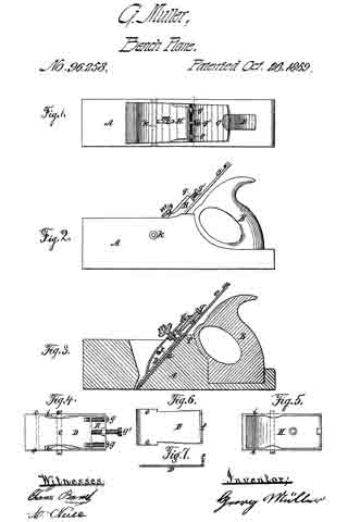
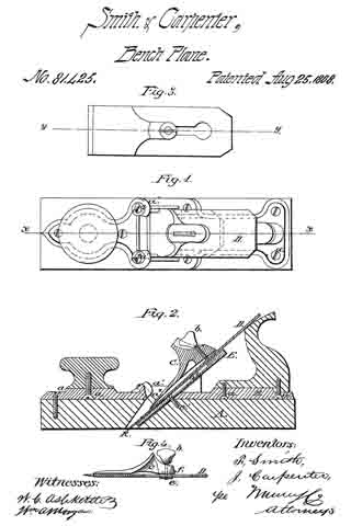
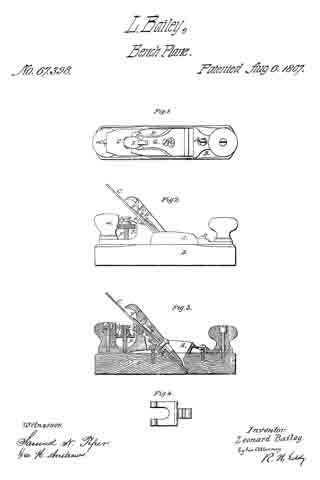
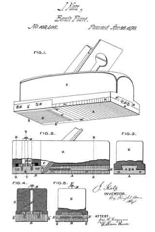
Figure 1 is a perspective under-side view of a plane-stock. embodying my improvement.
Figure 2 is a partly-sectionized side elevation thereof.
Figures 3, 4, and 5 are transverse sections at the lines X X, Y Y, Z Z, respectively.

I make the entire under surface of my improved plane-stock to consist of blocks or strips of bone, ivory, or similar hard organic substance, glued together in two pieces or slabs, A and B, of which the slab A, in rear of the throat C, fits, and occupies a dovetail excavation, D, on the under side of the wooden portion Z of the stock, to which it is firmly glued.

The component strips a and b of either slab are also firmly glued together, and additionally secured together by screws E.

The slab B, instead of being immovably fastened to the stock, is made capable of a slight longitudinal adjustment, and, for this purpose, is surmounted by a bolt or stern, F, which, extending upward through a slot, H, in the plane-stock, is secured by a nut, G, on the top of the stock.

Of the strips which compose the shiftable piece, B, the two outside ones, b’ b’, project rearward from the others, and enter jogs or gains a’ in the slab A.

Claim.

I claim herein as new and of my invention —

Facing a plane-stock with a congeries of strips of bone or like substance, glued and screwed together and fastened to the stock proper in the manner set forth.

In testimony of which invention I hereunto set my hand.

JULIUS KATZ.

Witnesses:
GEO. H. KNIGHT,
JAMES H. LAYMAN.

No. 99,275 – Improvement In Bench-Planes (Louis D. Tredway) (1870)

[paiddownloads id=”163″]99275


UNITED STATES PATENT OFFICE.

_________________

LOUIS D. TREDWAY, OF ST. LOUIS, MISSOURI.

IMPROVEMENT IN BENCH-PLANES.

_________________

Specification forming part of Letters Patent No. 99,275, dated January 25, 1870.

_________________

To all whom it may concern:

Be it known that I, LOUIS D. TREDWAY, of the city and county of St. Louis, and State of Missouri, have invented certain new and useful Improvements in Bench-Planes; and I do hereby declare that the following is a full, clear, and exact description of the same, reference being had to the accompanying drawings, which make a part of this specification, and in which —

Figure 1 represents a view in perspective of a plane embracing my improvements. Fig. 2 represents a vertical longitudinal section thereof. Fig. 3 represents a bottom view of the plane. Fig. 4 represents a view in perspective of the metallic shoe detached from the plane.

My improvements consist in the employment of a front adjusting-screw, in connection with a double-socketed boss projecting from the metallic shoe, and a vertical clamping-screw, whereby the said metallic shoe is not only adjusted to regulate the fineness of the cut, but held by said adjusting-screw, so as to prevent its being forced back against the edge of the bit, which would be the case if such adjustment simply depended upon the vertical clamp-screw; in constructing the metallic shoe with projections on each side thereof contiguous to the bit, for the purpose of forming a brace and guide to the lower end of the bit and a support to the throat end of the plate, which, in connection with the adjusting-screw, allows the said metallic shoe to be adjusted and held always in a line parallel with a line drawn through the center of the plane; and in beveling that edge of the metallic shoe adjacent to the bit, so as to maintain an angle of about ninety degrees with reference to the bit, for the purpose of allowing the throat of the plane to clear itself more rapidly of shavings and effectually prevent choking.

In the accompanying drawings, A represents the stock of the plane, constructed and provided with a bit, B, in the usual manner.

The metallic shoe D is fitted in a recess, D, made on the under side of the front portion of the plane, and extends from the end thereof to the edge of the bit B. It is provided with a boss, E,which extends within a cavity made in the stock A, so as to allow it to be adjusted nearer to or farther from the bit, and fitted l I with a screw-socket, a, to receive a vertical screw, F, by which the shoe C is clamped when adjusted. It is also provided with a screw-socket, b, in its front side, into which a horizontal adjusting-screw, G, is inserted. The head c of this screw G is secured within a thimble, H, countersunk in the front end of the stock A, by means of the shoulders formed by the head c on one side and a pin, d, on the other side of the thimble, passing through the screw G, so as to lock it therewith. This screw not only serves to adjust the metallic shoe C, but serves to brace it against any movement toward the cutting-bit B. This is especially advantageous, because the vertical clamping-screw F is liable to become loose, and is not sufficient to clamp the metallic shoe against the thrust of the plane when brought into sudden contact with a knot or other hard resistance in the timber. Neither is it sufficient to resist the tendency of the shoe to be forced backward against the edge of the bit in “backing the plane.” The adjusting screw G therefore avoids injury to the bit at all times by preventing its contact with the shoe C, which would be the case if the clamp-screw only were used. The inner edge of this metallic shoe C is cut out or made with a recess, D, for the reception of the cutting-edge of the bit B in such a manner as to leave an arm or projection, I, at each end thereof, and the space between these arms is just equal to the width of the bit, for the double purpose of forming a guide and support to the cutting end of the bit and lateral supports to the inner end of the shoe, for it will be seen that when the bit is placed between the arms I of the shoe its lower portion can have no transverse movement whatever, but must present a straight edge to the bottom of the plane, as the arms of the shoe form stops thereto on either side. Neither can the inner end of the plate have any side movement, because the arms are locked with the bit. This result could not be obtained without these supporting-arms, because the sides of the throat are liable to constant wear.

The end of the recessed portion D of the shoe C is beveled inward, as represented at J, so as to present an angle to the face of the bit of ninety degrees, more or less, and as this bevel opens into the throat K of the plane, it effectually prevents clogging, which would not be the case if the end of the shoe were att right angles to its face.

The head of the vertical clamp-screw F is fitted within a thimble on the upper side of the stock A, which is provided with a slot, L, to allow the screw-bolt which passes through it into the boss E, to move with the adjustment of the metallic shoe, and this screw must be unclamped whenever it is necessary to turn the adjusting-screw, and when the shoe is adjusted it is again clamped.

These improvements adapt the plane to perform the service of an entire set of bench-planes, and by them I am enabled to work a single-iron plane without a cap on the bit, and to do better and finer work than the ordinary plane with the cap, and with less labor.

Having described my invention, I claim —

The metallic face-plate C, constructed as described, in combination with the vertical clamping-screw F, the horizontal front adjusting and bracing screw, G, and the fixed thimble H, the whole constructed and arranged as described.

LOUIS D. TREDWAY.

Witnesses:
THOMAS KEYES,
F. D. LOVELL.

No. 99,137 – Improvement In Joiners’ Planes (George Cyrus Beckwith) (1870)

[paiddownloads id=”162″]99137


United States Patent Office.


GEORGE CYRUS BECKWITH, OF BOSTON, MASSACHUSETTS.

Letters Patent No. 99,137, dated January 25, 1870.
_________________

IMPROVEMENT IN JOINERS’ PLANES.

_________________

The Schedule referred to in these Letters Patent and making part of the same.

_________________

To all whom it may concern:

Be it known that I, GEORGE CYRUS BECKWITH, of Boston, in the county of Suffolk, and State of Massachusetts, have made a new and useful Invention, having reference to Joiners’ Planes; and do hereby declare the same to be fully described in the following specification, and represented in the accompanying drawings, of which —

Figure 1 is a top view;
Figure 2, a side elevation;
Figure 3, an end view; and
Figure 4, a longitudinal section of a joiners’ plane, containing my invention.

This plane has a stock, capable of being expanded and contracted, for the purpose of adapting it to hold plane-irons or cutters, and throat-pieces, of different sizes or widths. lt also has a new and peculiar mechanism for holding the plane-iron or cutter in place in the stock and throat-piece.

The stock is mainly composed of two jaws A B, the handle C being affixed to one of them, viz, that marked A.

Screws a a go through holes made in the jaw B, and screw into projections b b, extended from the jaw A.

Furthermore, a duplex thumb-screw, D, goes through the upper parts of the middles of the two jaws, and over the plane-iron or cutter E, which, with a wooden base-plate or throat-piece, F, is arranged between the two jaws, in manner as represented.

The duplex thumb-screw has two screw-threads c d, which are pitched or run in opposite directions, relatively to one another, one being what is usually termed “a right-hand screw,” and the other “a left-hand screw.”

One of these screws is screwed into the jaw-plate A, and the other into the jaw-plate B, the whole being so that a person, by revolving the duplex screw in one direction, will cause the jaw-plates to recede from one another, and, by turning the said screw in the opposite direction, will cause the two plates or jaws to approach one another. The screws a a serve to compress the jaws upon a throat-piece, when placed between them.

For better supporting a throat-piece by the jaws, I usually make each of the latter with a tongue, f, projecting from its inner side, such tongue being to enter a corresponding groove, g, made in the next adjacent edge of the throat-piece. This throat-piece may have a flat bottom, or it may have a bottom formed like that of any common moulding-plane.

It is intended, by my invention, to have a series of throat-pieces of different widths, and also to have a series of plane-irons or cutters, and cap-irons, to correspond with such, the same being to enable a joiner with one stock, and such a series of throat-pieces and plane-irons, and cap-irons, to compose such a plane as his necessities may require front time to time, whether such be a plane for moulding, or for plane-surface work.

The throat-piece F has a chip-throat, h, made through it, such being to receive the plane-iron or cutter E, and the cap-iron H.

For the support of the plane-iron, the two jaw-plates are provided with rebated ledges, one of which is shown at i, in fig. 4.

Furthermore, a stud, k, extends from the inner face of each jaw-plate, in manner as shown in figs. 1 and 4. These studs serve as bearings or fulcra for the cap-plate, which is passed underneath both of them, and, at its lower part, rests on the plane-iron or cutter.

There is, between the two screws of the thumb-screw D, an arm, l, which turns freely on the shank of the screw, or is pivoted to the screw, so as to be capable of turning up and down thereon.

A cammed lever, L, jointed to the said arm, either bears upon the plane-iron, or upon a spring, n, projected from the rear part of the arm, and resting on the plane-iron.

By pressing down the tail or handle o of the cammed lever L, the arm I will be elevated against the cap-iron, and the cam p of the lever will be forced against the plane-iron, and thus, by means of the iron and the cammed lever, and the supports of the plane-iron and the cap-iron, such plane-iron and cap-iron may be fastened simultaneously in place in the stock and throat-piece.

In the above-described plane, I claim, as my invention, the following, viz:

The stock, as composed of the two jaws A B, and their clamping and expanding dowels or screws a a D, substantially as set forth, in combination with a separate throat-piece, F, as explained.

Also, the combination of the arm Z and the cammed lever L, applied to the duplex extension-screw D, and arranged with the plane-cutter E and the cap~iron H, as explained.

GEORGE CYRUS BECKWITH.

Witnesses :
R. H. EDDY,
S. N. PIPER.

No. 98,108 – Improvement In Carpenters Plow (Royal B. Rice) (1869)

[paiddownloads id=”159″]98108


United States Patent Office.


ROYAL B. RICE, OF WILLIAMSBURG, MASSACHUSETTS.

Letters Patent No. 98,108, dated December 21, 1869.

_________________

IMPROVEMENT IN CARPENTERS’ PLOW.

_________________

The Schedule referred to in these Letters Patent and making part of the same.

_________________

To all whom it may concern:

Be it known that I, ROYAL B. RICE, of Williamsburg, in the county of Hampshire, und State of Massachusetts, have made and invented n new and useful Improvement in Carpenters’ Matching-Planes; and I do hereby declare that the following is a full, clear, und exact description of the construction and operation of the same, reference being had to the annexed druwings, making a part of this specification, in which —

Figure 1 is a side elevation of a plane embodying my improvement.
Figure 2, a detached end elevation of the plate in which is arranged the coulter.
Figure 3, at side elevation of the coulter detached from the plate,
Figure 4, at plan of the coulter inverted.
Figures 6 and 7, side and edge elevations of at tool for removing the coulter irom the plate.
In the accompanying drawings —

The part marked a represents the wood or body.
b, the fence.
c, the plate.
d, the bit.
e, the key.
f, the screw-knob, by turning which the foot g is raised or depressed, and the depth of the furrow thereby regulated.

h h’ are screws, provided with nuts i i’, also with corresponding nuts on the opposite side of the wood a, whereby is regulated the distance of the fence b from the plate c.

My invention consists in so constructing and arranging at coulter, with reference to the bit or iron d, that in “touguing” or “grooving” lumber, the edges of the shavings to be removed by the bit d shall have been previously cut by the coulter k, greatly facilitating such operations.

In practice, I make the coulter k of a rectangular form, providing the same with depending cutting-lips m m’, end with rebates n n’‘. In the plate c, I cut a notch, wherein I arrange the coulter, as in figs. 1 and 2. The coulter k is held in piece simply by fitting the notch in plate c snugly.

The lips m m, being lower than the bit d, first out the edges of the shavings, which are then removed by said bit.

The essence of my invention is the combination of the lips m m’ with the bit d.

By means of the tool represented in figs. 6 and 7 , the coulter k may be easily removed ffom plate c, and other coulters inserted to correspond with bits (d) of different widths that may be used in the same wood a.

Thus having described the construction and operation of my invention,

What I claim as new, and desire to secure by Letters Patent, is —

The coulter k, constructed and arranged with reference to bit d, as herein specified.

ROYAL B. RICE.

Witnesses:
T. M. CARTER,
J. B. GLEASON.

No. 97,328 – Improvement In Carpenters’ Plows (Harmon Vanbuskirk) (1869)

[paiddownloads id=”156″]97328


UNITED STATES PATENT OFFICE.

_________________

HARMON VANBUSKIRK, OF VIENNA, MICHIGAN.

IMPROVEMENT IN CARPENTERS’ PLOWS.

_________________

Specification forming part of Letters Patent No. 97,328, dated November 30, 1869; antedated November 21, 1869.

_________________

To all whom it may concern:

Be it known that I, HARMON VANBUSKIRK, of Vienna, in the county of Genesee and State of Michigan, have invented a new and useful Improvement in Plow-Planes for Carpenters’ Use; and I do declare that the following is a true and acurate description thereof, reference being had to the accompanying drawings, and to the letters of reference marked thereon, and being a part of this specification.

The nature of this invention relates to an improvement in the construction of plow-planes for the use of carpenters and joiners, by means of which the implement maybe set for use more accurately and readily than when constructed in the ordinary manner; and it consists in the employment of a right-and-left-hand screw, and a suitable guide, and arms secured to said guide and passing through the stock.

In the drawings, A represents the stock, and B the guide, which are both constructed in the usual manner.

C are the arms, rigidly secured at one end to the guide, while the opposite ends are inserted into and pass through proper holes through the stock, which holes should be of the size of the arms, allowing them to slide freely through said holes without play.

D is a right-and-left hand screw, provided with small hand-wheel a in its longitudinal center. Suitable female screws are cut through the body A and guide B, which engage with either end of this screw.

E are set-screws passing downward through the top of the body, and are intended, when the tool is set for use, to impinge on the arms and prevent the same from slipping.

The right-and-left-hand screw may be made of wood or metal, as may be most desirable.

In plow-planes of the usual construction the arms are both provided with suitable screw-threads and nuts, rendering it necessary for the operator to adjust both ends of the implement separately, requiring considerable skill and time. With my improvement the proper set is obtained by the one screw, and the operator saves time and trouble.

What I claim as my invention, and desire to secure by Letters Patent, is —

The right-and-left-hand screw D, when used in the construction of carpenters’ plow-planes, as herein described, in combination with stock A and guide B, all operating substantially as herein set forth.

HARMON VANBUSKIRK.

Witnesses:
JAS. I. DAY,
THOS. S. SPRAGUE.

No. 96,258 – Improvement In Carpenters’ Planes (Georg Müller) (1869)

[paiddownloads id=”154″]96258


UNITED STATES PATENT OFFICE.

_________________

GEORG MÜLLER, OF NEW YORK, N. Y., ASSIGNOR TO HIMSELF AND FRANCIS BURNET, OF SAME PLACE.

IMPROVEMENT IN CARPENTERS’ PLANES.

_________________

Specification forming part of Letters Patent No. 96,258, dated October 26, 1869.

_________________

To all whom it may concern:

Be it known that I, GEORG MÜLLER, of the city, county, and State of New York, have invented a new and useful Improvement in Carpenters’ Planes; and I do hereby declare that the following is a full and exact description of the construction and operation of the same, reference being had to the accompanying drawings, making part of this specification, in which —

Figure 1 is a top view ofi a carpenter’s plane containing my invention; Fig. 2, a side elevation, and Fig. 3 a vertical section, of same. Fig. 4 is an under side view of the retaining-box in connection with the sliding cap-iron; Fig. 5, an inner view of retaining-box with cap-iron removed; Fig. 6, a plan of the sliding cap-iron, and Fig. 7 a longitudinal section of said iron.

This invention relates to a novel device for adjusting the cap and bit-irons of a carpenter’s plane in relation to each other and to the plane, and holding the same firmly in position by means of a swinging box or frame, which is pivoted to the plane-stock, and on which the cap-iron slides, the said box having set-screws for adjusting, retaining, and bracing the box, cap-iron, bit-iron, and plane-stock together, and at the same time rendering the cutting-irons capable ofthe nicest adjustment and stability in relation to each other and to the face of the plane-stock.

Having described the nature of my invention, I will now describe its construction and mode of operation.

In the drawings, A is the plane-stock, B the handle, and C the plane-iron or cutting-bit. D is the cap-iron, having projections e e, which slide on the ways of the box, and having, also, a lip or projection, f, at right angles to its face, in which set-screws (which pass through the end of the box marked g g g’) operate, for purposes hereinafter explained. H is the retaining-box, which receives the cap-iron D, and has ways i i, on which the projections e e of the cap-iron slide, while the projection or lip f of said cap-iron slides on the interior of the box, Fig. 4. This box H is pivoted to the plane-stock at k, and has a clamping-screw, m, for the purpose of bracing the cap and bit irons together, and against the rear, a, of the throat of the plane-stock.

To arrange my plane for operation, I place the bit C in the throat a of the plane-stock. I next set the cap-iron D within the box H and insert the adjusting and clamp screws in their places, and I place the box so equipped in the throat of the plane. I now pass the pivot k through the throat of the plane, and through the box H; and for adjustment of the cap-iron in relation to the bit-iron in a longitudinal or transverse direction I simply turn the screws g g, or either of them, (as the case may be,) back or forth, and when so adjusted hold the cap-iron D in position by the screw g’, abutting against the lip f of the cap-iron, and I next clamp the whole together by means of the screw m, when my improved plane is ready for operation.

It will be seen from the above that by means of the pivot k and clamping-screw m the box H, cap-iron D, and bit-iron C are braced firmly together and against the plane-stock, equally distributing the pressure over the surface of the part a of the throat of the plane: Furthermore, by this arrangement the box H closely tits the throat of the plane laterally, the movements of the cap-iron being pertormed within the box; besides, the box can be brought near the mouth of the plane, thereby giving strength and stability to the cutting-irons, and at the same time easy exit to the shavings, for the reason that I dispense with the prize fork or carrier F, used in the subject of a patent granted me on the 29th day of May, A. D. 1866, and on which I consider my present invention an improvement, inasmuch as the swell on the box E, for reception of the prize-fork, prevented the approach of the box toward the mouth of the plane or end of the cutting-irons, rendering the said irons partially unstable, while it also prevented the easy exit of the shavings, or rather tended to choke the throat of the plane; and, besides this, the said box E was slotted for reception of the joint-pin G, and did not fill the throat of the plane laterally, as provision had to be made for the lateral movements of the cap-iron, and both the box and prize-fork were slid together, while in my present improvement the box H is stationary, while the cap-iron D slides transversely and longitudinally on the ways of the box; and thus I produce an improvement on my former plane, which can be manufactured for two-thirds of its cost.

What I claim as my invention, and desire to secure by Letters Patents, is —

The arrangement of the stationary box H, pivoted to the plane-stock, and fitting closely the the throat thereof laterally, in combination with the cap-iron D, which is moved and adjusted beneath the said box, substantially as and for the purpose herein specified.

In testimony whereof I have hereunto set my signature this 21st day of August, A. D 1867.

GEORG MÜLLER

Witnesses:
FRANZ BERNET;
A. NEILL.

No. 96,052 – Improvement In Plane (E.G. Storke) (1869)

[paiddownloads id=”153″]96052


United States Patent Office.


E. G. STORKE, OF AUBURN, NEW YORK.

Letters Patent No. 96,052, dated October 19, 1869.
_________________

IMPROVEMENT IN PLANE.

_________________

The Schedule referred to in these Letters Patent and making part of the same.

_________________

To all whom it may concern:

Be it known that I, E. G. STORKE, of Auburn, in the county of Cayuga, and State of New York, have invented a new and useful Method of Preventing the Adhesion to the Wood, of the Faces of Metallic Planes; and I do hereby declare that the following is a full, clear, and exact description of the same, reference being had to the annexed drawing, marked “A,” making part of this specification, in which is represented the face of a metallic plane, fluted, grooved, or channelled, according to the plan of my invention.

Those flutes, grooves, or channels, may be more or less in number, and cut to a greater or less depth, provided the object be thereby attained of relieving all extra and unnecessary friction.

The object, however, is fully attained by making them about one thirty-second of an inch deep, one sixteenth of an inch broad, and one eighth of an inch asunder.

Fully one-half of the bearing-surface of the face of the plane may be thus removed, and thus to that extent diminish the points of contact, and the consequent friction, and, at the same time, preserve the full perfection of the working-face of the plane, including its throat.

It has long been known to mechanics that metallic planes have adhered to the wood much closer than wooden planes, and therefore required much more power to operate them.

This excessive friction was caused by their exact and even faces, which were not materially varied by use or atmospheric changes.

When used on very level surfaces, there were so many points of contact that the friction was troublesome, and the adhesion was further increased by atmospheric pressure, as partial vacuums would thus be formed.

The practical effect of this has been to prevent, in a large degree, the introduction and general use of metallic planes.

The object of my invention is twofold, namely, to remove about one-half of the surface of the face of the plane, so that there shall be fewer points of contact, and to form free air-channels, so that no vacuums can be formed, or any trouble arise from atmospheric pressure, however perfect the plane or true the surface on which it is moved.

I effect these two objects by fluting, grooving, or channelling the faces of metallic bench or other planes for wood-workers, as above specified, parallel to their length, or in some equivalent way.

What I claim as my invention, and desire to secure by Letters Patent, is —

A metallic plane, having the face grooved in lines parallel to the sides, in the manner and for the purpose specified.

E. G. STORKE.

Witnesses:
U. L. STORKE,
T. B. BARBER.

No. 91,990 – Improvement In Wood-Plane (Paul Viccellio) (1869)

[paiddownloads id=”152″]91990


United States Patent Office.


PAUL VICCELLIO, OF NEW ORLEANS, LOUISIANA.

Letters Patent No. 91,990, dated June 29, 1869.
_________________

IMPROVEMENT IN WOOD-PLANE.

_________________

The Schedule referred to in these Letters Patent and making part of the same.

_________________

To all whom it may concern:

Be it known that I, PAUL VICCELLIO, of the city of New Orleans, in the State of Louisiana, have invented new and valuable Improvements in Wood-Planes; and I do hereby declare that the following is a full and exact description thereof; reference being had to the accompanying drawings, and to the letters of reference marked thereon.

The object of this invention is to so construct aplane that the cap may be nicely adjusted upon the plane-bit, without regard to the distance that said bit may project beyond or below the face of the plane; and lt consists of the sliding adjustable, and perpendicular cap, as applied to and adjusted upon the plane bit.

Figure 1 is a longitudinal section of the plane;
Figure 2 is a top view ofthe plane;
Figure 3 is a perspective view of the cap and its attachments for operating it; and
Figure 4 is a back view of same.

To enable others skilled in the art to make and use my invention, I will describe its construction and operation.

A represents the wood or stock of a common smooth plane.

b is the holding-wedge to plane-bit c. The plane-bit c is set at an acute angle to the face of the plane, in order to secure an easy cut by the bit.

B represents the throat of the plane, with the rear or back side perpendicular, as seen in fig. 1.

Into the wood of the plane, on its top, is a metal plate, a’, sunk flush with the wood, and held in its place by screws e’, through holes e in plate a.

The front edge of plate a’ is recessed nearly its whole length, or so as to receive cap a in grooves that are cut therein, as seen in figs. 2 and 3, and in said grooves the cap a can freely slide.

Upon the back side of cap a is a lug-nut, a”, having a female screw-thread therein.

There is a thumb-screw D, having collars d and d’, upon each side of plate a’, so that it is securely held in its position, and upon the lower end is out a screw-thread which enters into lug-nut a”, and by turning the thumb-screw, the cap a is raised or depressed, as may be desired.

Cap a is acutely bevelled on its rear lower edge, so as to present a sharp edge upon the plane-bit c, as seen in fig. 1, and it can readily be seen that by depressing the cap by means of screw D, the most delicate adjustment of the cap upon the plane-bit can be obtained. The bit c can be taken out of the stock A, by releasing wedge b, which, in order to hold the bit firmly in position tbr cap a to act upon, is put in the rear side of said bit c, and is just as effective in holding, adjusting, or releasing the bit, as if it was placed betore it.

By placing the cap a in a perpendicular, and the bit at an acute angle with the face of the plane, the shaving is easily severed from the wood, and the cap a crimps the sharing, and insures a clear smooth out upon the wood, however cross-grained or knotty the wood may be. At the same time the cap is straight on its face, causing only a single bend of the shaving to follow up the face of the cup through the throat and out ot’ the plane, without, in the least, clogging or crimping.

The parts are all simple and cheap in construction and operation, less liable to get out of order by reason of the fewer parts, and making, as a whole, a plane of less cost, more effective and satisfactory in its use, and less trouble to manage while so in use.

I am aware that there are many devices for adjusting plane-bits in the stock, as well as many for adjusting the cap upon the bit.

I am also aware of the plane described in Patent No. 50,378, where the cap is adjusted by means of a set-screw upon the plane-bit.

None of the devices therein described do I claim, as the construction of that plane is more expensive, has more parts, thus increasing the liability to get out of repair, and so constructed that the shaving has to go through a secondary bend to be successfully discharged from the plane.

My improvement can be applied to all kinds of planes, such as jack or fore-planes, and jointers, as well as smooth-planes.

Having thus described my invention,

What I claim, and desire to secure by Letters Patent, is —

The above-described plane, when composed of the combination of the bit c, wedge b, cap a, and its adjusting-devices, with the stock A, all constructed to operate in the manner and tbr the purpose substantially as described.

PAUL VICCELLIO.

Witnesses:
WM. MANTEY,
F. LURGES.

No. 105,869 – Improvement In Carpenters’ Planes (Charles E. Tucker) (1870)

[paiddownloads id=”169″]105869


United States Patent Office.


CHARLES E. TUCKER, OF BOSTON, MASSACHUSETTS, ASSIGNOR TO
HIMSELF AND T. L. APPLETON, OF SAME PLACE.

Letters Patent No. 105,869, dated July 26, 1870
_________________

IMPROVEMENT IN CARPENTERS’ PLANES.

_________________

The Schedule referred to in these Letters Patent and making part of the same.

_________________

To all whom it may concern:

Be it known that I, CHARLES E. TUCKER, of Boston, in the county of Suffolk and State of Massachusetts, have invented certain new and useful Improvements in Carpenters’ Planes; and I do hereby declare that the following is a full and exact description thereof reference being had to the accompanying drawing and to the letters of reference marked thereon.

To enable others skilled in the art to make and use my invention, I will proceed to describe its nature, construction, and use.

The nature of my invention consists in the construction and arrangement of the parts composing my invention, as will he hereinafter fully described and set forth.

Drawing.

Figure 1 represents a perspective view of my invention.
Figure 2 is a plan, showing the under side of the plane.
Figure 3 is a cross-section of the plane.

General Description.

The body of my plane consists, essentially, of two parts, C and C’, each of which parts have a downwardly projecting flange, H and H’; these two flanges together constitute the fence, and, being connected with the parts C C’, are adjustable in relation to each other.

This adjustment is effected by loosening the screws E and E’, fig. 1, which will allow the part C, to which the flange H is attached, to he moved, so that the flange H may be in contact with the flange H’, as shown in fig. 1, or may be at a distance from it, as shown in figs. 2 and 3.

The width of groove to be cut will depend upon the distance that the flanges H and H’ are from each other, and, as the flanges are adjustable, it will be seen that, with this plane, a groove of any width may he cut.

A and A’ are plane-irons attached to the parts B and B’ by set-screws S and S, as shown.

If desirable, a single iron may be used to take the place of the two irons A and A.

When a single iron is used it must be changed for each adjustment of the flanges H and H’, that is, for each width of groove required.

Each part of the plane is provided with a marker, one of which is shown at M, arranged as in an ordinary grooving-plane.

I am aware of the patent granted to T. Duvall, March 23, 1869, and therefore do not claim the features of his device.

Claim.

What I claim as my invention, and desire to secure by Letters Patent of the United States, is —

The parts C C’, flanges H H’, set~screws E E’, parts B B’, and planing-knives A A’, when constructed and arranged substantially as shown and described.

CHARLES E. TUCKER.

Witnesses:
FRANK G. PARKER,
E. A. NICKERSON.

No. 81,425 – Improvement In Planes (F. Smith And I. Carpenter) (1868)

[paiddownloads id=”141″]81425


United States Patent Office.


F. SMITH AND I. CARPENTER, OF LANCASTER, PENNSYLVANIA.

Letters Patent No. 81,425, dated August 25, 1868.
_________________

IMPROVEMENT IN PLANES.

_________________

The Schedule referred to in these Letters Patent and making part of the same.

_________________

TO ALL WHOM IT MAY CONCERN:

Be it known that we, F. SMITH and I. CARPENTER, of Lancaster, in the county of Lancaster, and State of Pennsylvania, have invented a new and useful Improvement in Joiners’ Planes; and we do hereby declare that the following is a full, clear, and exact description thereof, which will enable those skilled in the art to make and use the same, reference being had to the accompanying drawings, forming part of this specification.

The nature of our invention relates to improvements in joiners’ planes, whereby it is designed to render the stocks less liable to warp, to regulate the weight of the same, to provide for a more perfect delivery of the shaving, adjusting the some to be used as a single or a double plane, and adjusting the mouth, so as to govern the width of the same for the passage of the shaving.

And it consists in constructing the stock partly of iron, substituting, for the tapered notches of wooden stocks for holding the tightening-wedges, set-screws for holding the wedge, which is made of metal, and provided with an additional tightening-screw in its upper end, which works against the face ofthe plane-bit, or into a swivel-nut which slides in the slots of plane-bits, as ordinarily constructed, and providing a wooden wedge at the back side ofthe plane-bit, as will be more fully described on reference to the accompanying drawings, wherein —

Figure 1 represents a plan view of our improved plane.
Figure 2, a central section ofthe same on the line x x of fig. 1.
Figure 3, a plan view of a part of our improvement applied to plane-bits, having the ordinary slot in the same; and
Figure 4 a section on the line y y of fig. 3.

Similar letters of reference indicate corresponding parts.

A represents the wood part of the stock, and B the iron portion of the same, which are secured together by the screws d d.

The part B may-be made of cast iron, and of different thicknesses, as may be desired to govern the weight of the plane.

The handle and knob may be secured to the part B in suitable sockets provided for them by the screws d d.

The part B is provided with lugs, a1 a1, through which set-screws, a2 a2, are arranged to hold the cap.

C represents a metal cap or wedge, provided with a set-screw, b, by which it may be, if desired, raised at its upper end from the bit D.

The said cap is provided with a raised portion, C’, in advance of the set-screw b, which rises by a gentle curve from the wedge portion of the same, so as to prevent the shavings from clogging against the screw.

When a plane-bit is used without a slot, as in figs. 1 and 2, we use a set-screw arranged as therein shown, but to adapt our improved tightening-wedge to plane-bits of the old construction, having the slot for set-screws as ordinarily constructed, we attach, to the ends of the set-screws, swivel-nuts, e, having slots in two edges of the same, which admit it to slide within the slot in the plane-bit, by taking the edges of the bit forming the side walls of the slot in the latter into the slots in the nut, the nut being of the proper size to be admitted through the enlarged portion of the slot in the plane-bit.

E represents a wedge, which may be made of wood or metal, and arranged in the bottom of the mouth of the stock under the plane-bit, and held there by the set-screw e1 passing through a slot in the said wedge, whereby it may be adjusted within the mouth ofthe stock.

The face of the wedge next the plane-bit is provided with a recess, e2, to admit the nut e of the set-screw.

The under side of the upper end of the metallic wedge C is provided with a recess, f, (see fig. 4,) when the nut e is used.

By the use of our improved wedge, the same plane-bit may be used for a double or single bit.

When used as a single bit, it may be applied as shown in fig. 2, and when used as a double bit, the set-screws a2 may be withdrawn, so that the wedge may be moved down sufficiently near to the edge of the bit to serve the purpose of a double bit.

By adjusting the upper end of the wedge by a set-screw, b, the width of the mouth may be adjusted to suit the different requirements of different kinds of work, or of different kinds of wood, or may be made of uniform width from bottom to top.

The same may be also adjusted by the wedge E to some extent, but the more important function of the wedge E is to govern the width of the throat at the cutting-edge of the bit, as at k, as will be readily understood.

In adjusting the wedge to the bit, when constructed as shown in figs. 3 and 4, the lower end of the wedge is placed at the right position with reference to the cutting-edge of the bit, and the thumb-screw turned to the left until the upper end of the wedge is screwed tightly to the bit. They are then inserted in the stock, the set-screws a2 adjusted to their right positions, when the set-screw b is turned in the opposite direction, and the wedge forced out against the set-screws a2.

The metallic part, B, of our stock may be taken off from a worn-out wood stock, and readily applied to a new one, or old plane-stocks of ordinary construction may be readily fitted to be attached to it.

We claim as new, and desire to secure by Letters Patent —

1. The adjustable cap, provided with the guard in front of the set-screw b, substantially as and for the purpose described.

2. The set-screws a2 in the lugs a1, arranged to clamp upon the adjustable wedge C, as herein shown and described for the purpose specified.

F. SMITH,
I. CARPENTER.

Witnesses:
P. G. EBERMAN,
F. R. GRUGER.

No. 81,335 – Improvement In Planes (George Buckel) (1868)

[paiddownloads id=”140″]81335


United States Patent Office.


GEORGE BUCKEL, OF DETROIT, MICHIGAN.

Letters Patent No. 81,335, dated August 25, 1868
_________________

IMPROVEMENT IN PLANES.

_________________

The Schedule referred to in these Letters Patent and making part of the same.

_________________

TO ALL WHOM IT MAY CONCERN:

Be it known that I, GEORGE BUCKEL, of Detroit, in the county of Wayne, and State of Michigan, have invented a new and improved Plane; and I do hereby declare that the following is a full, clear, and exact description thereof, which will enable those skilled in the art to make and use the same, reference being had to the accompanying drawings, forming part of this specification.

The object of this invention is to provide a plane so arranged that the out may be regulated either in a positive manner or by the pressure of the hand, and that the bit may be raised out of contact with the board being operated on when it is being moved back.

It consists in making the stock in two parts, one part, which supports the bit, being pivoted at the rear end in a longitudinal channel through the other, and provided with a spring and adjusting-screw at the other end, the springs being so arranged as to throw the bit out of contact with the board when the pressure of the hand is removed, and the set-screw governs the amount of such movement.

Figure 1 represents a longitudinal sectional elevation of my improved plane, and
Figure 2 represents a transverse section on the line x x of fig. 1.

Similar letters of reference indicate corresponding parts.

A represents one part of the stock, which is provided with a deep and wide channel in the upper portion from end to end, as clearly shown in fig. 2, and with an opening through the bottom for the plane-bit, as shown at B.

C represents the other part of the stock, which is fitted to the channel in the part A, and pivoted thereto at the rear end, as shown at D.

It is provided with the usual opening for the plane-bit and wedge, and for the escape of the shavings, and at the front end with a spring, E, in a recess in the under face of the same. The said spring bears upon the bottom of the channel, and has a constant tendency to raise the part C away from the said bottom of the channel.

F represents a set-screw, which screws into a nut in the bottom of the channel in the part A, and arrests the upward movement of the part C, due to the action of the spring. The said screw may be adjusted to regulate the said movement of the part C, as desired.

The plane-bit being set by the wedge in the part C as desired, the operator, in using the plane, may, on shoving it forward, so press down the front end of the part C as to cause the bit to take the full cut for which it is set, or, by a lighter pressure, take but a part of the said cut, and when the cut has been made, and the pressure necessary for making the same is relaxed, the spring will throw the part C up so as to take the edge of the bit out of contact with the surface being planed while the plane is being drawn back, thereby protecting the edge from being worn round from that cause.

I claim as new, and desire to secure by Letters Patent —

A plane-stock, constructed of the parts A and C, pivoted together, and provided with a spring, E, and set-screw, F, substantially as and for the purpose set forth.

The above specification of my invention signed by me, this eighth day of July, 1868.

GEORGE BUCKEL.

Witnesses:
JOSEPH KUHN,
CHARLES STARKLOFF.

No. 81,879 – Improvement In Planes (Alfred H. Comp) (1868)

[paiddownloads id=”143″]81879


UNITED STATES PATENT OFFICE.

_________________

ALFRED H. COMP, OF MOUNT JOY, PENNSYLVANIA.

IMPROVEMENT IN PLANES.

_________________

Specification forming part of Letters Patent No. 81,879, dated September 8, 1868.

_________________

To all whom it may concern:

Be it known that I, ALFRED H. COMP, of Mount Joy, in the county of Lancaster and State of Pennsylvania, have invented a new and Improved Device for Adjusting the Width of the Mouth in Smoothing and other Planes; and I do hereby declare that the following is a full, clear, and exact description of the construction and operation of the same, reference being had to the accompanying drawings, making a part of this specification, in which —

Figure 1 shows the application of my adjusting-plates to the bottom of an ordinary smoothing-plane. Fig. 2 shows the plates separated; Fig. 3. the same reversed; Fig. 4, both plates joined, showing the outer face; Fig. 5, the same, showing the inner face and rear-edge view.

The nature of my invention consists in the construction of a dovetailed plate, T-shaped, operated by a horizontal screw, and inserted flush with the wood in the bottom or face of the plane before the mouth, and so as to regulate the width or opening of the mouth at pleasure.

To enable others skilled in the art to make and use my invention, I will proceed to describe the same.

Figs. 2 and 3 clearly show the two plates and appliances B B’.

The bed-plate has a central open space with beveled sides and slide-bearings, the sides of one end slotted or perforated for screws. The other end has a raised flange, E, perforated for a thumb or ordinary cut-headed screw-bearing, as also a screw-hole for attaching against the end of the plane, flush with the wood. The adjusting or sliding T-plate A fits into the space and beveled sides, and is provided with a raised flange, D, having a perforation cut with a thread for the screw C, which is held by a pin or key, K, in the outer flange E on plate B. By this screw C the adjusting-plate A is pushed out or drawn in. Both plates are smooth, and flush on the face with the wood when closed up, as shown by Fig. 4. The same in Fig. 1 is shown pushed out to narrow the mouth.

It is well known that hard and cross-grained or green wood is apt to tear in and get rough when the mouth of the plane is wide, as it should be, for dry and .soft wood, to deliver the shavings freely, and by narrowing the mouth the same plane is equally well adapted, and can be, in fact, regulated with ease, for any kind of wood.

This device can be easily affixed to ordinary planes, and requires no special construction of the throat, as in inventions such as Patent No. 14,436, (1856,) or No. 43,053, (1864,) for bench-planes, where a slotted wedge is used in the throat by means of a set-screw and the like, which differ substantially from my combined plates and screw inserted in the bottom of the plane, as set forth.

What I claim as my invention, and desire to secure by Letters Patent, is —

The beveled sliding plate A and beveled grooved plate B B, with their screw-bearings, when constructed to operate in the manner and for the purpose specified.

A. H. COMP.

Witnesses:
J. GERHART METZGER,
C. M. MARTIN.

No. 82,450 – Improvement In Carpenters’ Planes (John Blake Tarr) (1868)

[paiddownloads id=”146″]82450


United States Patent Office.


JOHN BLAKE TARR, OF CHICAGO, ILLINOIS.

Letters Patent No. 82,450, dated December 18, 1868.
_________________

IMPROVEMENT IN CARPENTERS’ PLANES.

_________________

The Schedule referred to in these Letters Patent and making part of the same.

_________________

TO ALL WHOM IT MAY CONCERN:

Be it known that I, JOHN BLAKE TARR, of Chicago, Cook county, State of Illinois, have invented an Improved Carpenters’ Plane; and I do hereby declare that the following is a full, clear, and exact description thereof, reference being had to the accompanying drawings, making part of this specification, in which —

Figure 1 is a longitudinal section, taken vertically through the centre of my improved plane.
Figure 2 is a similar view of the same parts, showing the plane-iron set to cut a very thick shaving.
Figure 3 is a perspective view of the plane complete.

Similar letters of reference indicate corresponding parts in the several figures.

This invention relates to an improvement in adjusting and setting plane-irons of carpenters’ or bench-planes, of various descriptions, whereby these irons or blades can be adjusted and set at any desired pitch for removing very thin or very thick shavings, by simply turning a thumb-screw, which is applied to the plane-stock and blade in such manner as to give a greater or less bow or bend to the latter, according to the pitch required, as will be hereinafter described.

Before my invention, plane-irons have been applied to plane-stocks by means of clamping-devices, which bent or bowed the irons, so as to increase or diminish the pitch of their cutting-edges for removing thick or thin shavings. The objection to said devices is, that it is necessary to render the plane-irons comparatively loose in adjusting their cutting-edges for removing thick shavings. The object of my invention is, to so construct and apply adjusting-clamps to plane-irons and their stocks, that the greater the amount of pitch given to the cutting-edges of the irons, the tighter will they be held, as will be hereinafter described.

To enable others skilled in the art to understand my invention, I will describe its construction and operation.

In the accompanying drawings —

A represents the stock of a jointing-plane, having my invention applied to it. This stock is constructed in the usual well-known manner, and is also in the blade or plane-iron B, as will be seen by reference to figs. 1 and 2.

Near the upper termination of the inclined bed a of the plane-stock, a recess is made, into which is fitted and firmly secured a plate, b, having a deep notch or slot formed in it, which should be exactly in the centre of the width of the stock.

In rear of this slotted plate b, and in a line therewith, a hole is bored into the plane-stock, and screw-tapped for receiving a male-screw, C, which has a T-head formed upon its upper end. A similar T-head screw, D, is tapped into the plane-stock in front of the slotted plate b. Both screws, C and D, are in the same vertical plane, and both have the same degree of inclination backward, as shown in figs. 1 and 2. The screw C projects from the top of the plane-stock, and the screw D projects from the inclined bed a of this stock. They are arranged about equal distances from the slotted plate b, and may be adjusted further into or out of the stock at pleasure, by turning them to the right or left.

A thumb-screw, E, is tapped through a sliding nut, F, applied to the plane-iron B, which screw has an annular groove formed in it near that end which is opposite its head. This groove leaves a contracted neck, which is received by the groove or notch in the upper edge of fixed plate b, as shown in figs. 1 and 2, thus affording a purchase for the screw E, when applied in its place.

The nut F has grooves in its sides, at right angles to the axis of the screw E, which grooves receive the inner edges of the plane-iron B, when the nut is applied in the slot thereof, and thus afford an attachment for the nut to the plane-iron.

The heads on the screws C and D are turned so as to bring them in line with the length of the slot through the plane-iron.

The nut F, with screw E applied to it, is slipped upon the plane-iron, and the latter adjusted in place in the plane, so that the neck of the screw E will be received by the slot or notch on plate b, and the screws C D passed through the plane-iron slot, as shown in the drawings. The screws C and D are then turned around so as to leave their heads cross-wise of the slot through the plane-iron, thereby causing them to serve as bearings against wliich the plane-iron is pressed upward, by tightening the screw E.

It will be seen, from the above description, that the plane-iron is forced upward and forward against the lower edges of the heads of screws C D, by means of an adjusting-screw, which is between said screws; consequently the degree of inclination of said plane-iron will be governed by the relative positions of the beads of said screws C D, which latter can be adjusted at pleasure, when the plane-iron is released from pressure.

It will also be seen that by setting the screw E up tight, the plane-iron will be more or less curved or bent out of a straight line, as shown in fig. 2, the result of which will be to throw back the cutting-edge of said iron and increase or diminish its pitch, and the size of the throat. By this arrangement, a very nice adjustment can be effected by simply turning the thumb-screw E, while, at the same time, the greater the pitch attained, the stronger will the plane-iron be held in place.
To remove the plane-iron for sharpening it, it is only necessary to loosen the screw E, and turn the heads of the screws C D in line with the slot through the plane-iron, when the latter may be slipped out of its place, and the screw E and its nut detached from it.

I do not claim, broadly, adjusting the cutting-edges of plane-irons by pressure applied between the upper and lower ends of the iron; but

What I do claim as my invention, and desire to secure by Letters Patent, is —

1. The combination of the central clamping and tightening-device with the adjustable supports C D, the said device and the supports being applied to a plane-stock, and in the relation to the plane-iron thereof, substantially as and for the purpose herein described.

2. Making the two supports or abutments C D adjustable, substantially as and for the purpose herein described.

3. Applying pressure to a plane-iron between two supports, C D, through a device, E F, substantially in the manner and for the purpose herein described.

4. Changing the pitch and tightening the plane-iron by the same means, and at the same time, the means employed being constructed and operated substantially as herein described.

5. The adjusting of the plane~iron by means of the clamping-device composed of the screws C, D, and E, nut F, and plate b, and applied in such manner that the bit is tightened, and the pitch changed at the same time, and by the same means, when constructed to operate substantially in the manner described.

6. Arranging the plane-iron beneath the heads or shoulders of two adjustable bearings, C D, and under a shoulder of a nut, F, so that it may be adjusted by means of either or both ofthe bearings C D, and may be tightened and have its pitch changed by the screw E, all substantially in the manner and for the purpose described.

JOHN BLAKE TARR.

Witnesses:
EDW. SCHAFER,
EDM. F. BROWN.

No. 86,295 – Improvement In Bench-Planes (Philander S. Foster) (1869)

[paiddownloads id=”147″]86295


United States Patent Office.


PHILANDER S. FOSTER, OF RICHMOND, MAINE.

Letters Patent No. 86,295, dated January 26, 1869.
_________________

IMPROVEMENT IN BENCH-PLANES.

_________________

The Schedule referred to in these Letters Patent and making part of the same.

_________________

To all whom it may concern:

Be it known that I, PHILANDER S. FOSTER, of Richmond, in the county of Sagadahoc, and State of Maine, have invented a new and valuable Improvement in Bench-Planes; and I do hereby declare that the following is a full, clear, and exact description of the construction and operation of the same, reference being had to the annexed drawings, making a part of this specification, and to the letters and figures of reference marked thereon.

Figure 1, of the drawings, is a side view of my bench-plane;
Figure 2 is a longitudinal section; and
Figure 3 is a cross-section of the same.

My invention relates to that class of bench-planes constructed partly of wood and partly of metal; and It consists in providing a remedy against the difficulty commonly called choking, by means that are more permanent and efficient than have heretofore been devised.

By my device, also, a wider bit may be used, and consequently a wider shaving be cut, than by the ordinary bench-planes.

The letter A, of the drawings, represents the removable and adjustable wooden front of the plane, and the letter B is the wooden rear thereof.

The part A is constructed with a slot in its middle, running lengthwise, as shown on fig. 2, adapted to hold and operate with the thumb-screw C. This slot is marked H on the drawings.

The letters D are metallic plates, adjusted respectively on each side of the wooden parts of the plane, in the manner shown on figs. 1 and 3.

That portion of these metallic side plates respectively which is adjusted forward of the bit and throat, is constructed in a bevelled form, as shown on fig. 3, and is adapted to corresponding grooves, out in the sides of the part A, in which grooves it is held securely and firmly by the thumb-screw C, in conjunction with its bevelled form so resting in its grooves.

The part A is cut off square at its rear end, leaving a small bevel at the point c, upon which the hammer may be used.

I sometimes also arrange metallic boxings in the grooves of the part A, adjusted to the plates D. These boxings will save the wear of the wood, and when properly oiled, will aid in the adjustment of said part to the bit of the plane.

The thumb-screw G passes through both plates D and the slot H, and serves as a means of tightening, loosening, and fastening the part A, at the will of the operator.

The letter E is the bit, and letter F is the wedge of the plane. These are adjusted in diagonal slots, formed in the inner sides of the plates D respectively, in the manner shown on fig. 2.

The fact that the bit and wedge are adjusted in plates of metal, instead of the wooden throat of the plane, as is usual, justifies the manufacturer in adapting a bit to the plane, that shall be wider, and consequently shall out a wider shaving than is prudent in planes wherein the bit is adjusted in wood only.

It will readily be perceived that by the upright formation of the rear end of part A, the plane is provided with a large open throat, which greatly lessens the danger of choking, and that in case such an event occurs, the chips in the throat may be easily loosened and removed, by moving the part A forward. This movement is effected by unscrewing the thumb-screw C, and striking a gentle blow with a hammer on the bevel c.

What I claim as my invention, and desire to secure by Letters Patent, is —

A bench-plane, having bevelled metallic side plates D, wooden sections A and B, slot H, and thumb-screw C, when the same are constructed and arranged as specified.

In testimony that I claim the above, I have hereunto subscribed my name, in the presence of two witnesses.

PHILANDER S. FOSTER.

Witnesses :
WM. S. HAGAR,
WM. H. STUART.

No. 72,443 – Improvement In Carpenters’ Planes (Leonard Bailey) (1867)

[paiddownloads id=”134″]72443


United States Patent Office.


LEONARD BAILEY, OF BOSTON, MASSACHUSETTS.

Letters Patent No. 72,443, dated December 24, 1867.
_________________

IMPROVEMENT IN CARPENTERS’ PLANES.

_________________

The Schedule referred to in these Letters Patent and making part of the same.

_________________

TO ALL PERSONS TO WHOM THESE PRESENTS SHALL COME:

Be it known that I, LEONARD BAILEY, of Boston, in the county of Suffolk, and State of Massachusetts, have invented a new and useful Improvement in Bench-Planes; and I do hereby declare the same to be fully described in the following specihcation, and represented in the accompanying drawings, of which —

Figure 1 is a top view, and Figure 2, a longitudinal section of a plane-iron and its cap-iron, and their holding-devices, such cap-iron being constructed in accordance with my improvement.

Figure 3 is a longitudinal section of the plane-iron and cap-iron, as ordinarily constructed, that is to say, with one bend, a, only near the bearing-edge of the cap-iron.

My object is to use very thin steel plane-irons, and in so doing I find that they are liable to buckle under the pressure of the cap, which causes them to chatter, and makes them otherwise imperfect; and my invention consists in the providing of an auxiliary point of contact between the cap and plane-iron, and at the point where the plane-iron tends to buckle or rise from its bed or base, and thus have a pressure at that point in addition to that at the cutting-edge, which firmly holds this thin plane-iron to its bed.

The cap-iron, as commonly constructed, that is, as shown at D, in fig. 3, when applied to the plane-iron E, will rest thereon only at the extreme lower end of the cap-iron, and also at or very near its upper end. There will be along angular space, b, between the two irons, when they are clamped together by the holding-devices which are represented in figs. 2 and 3, at A, B, and C, and consist of a screw, A, a bearing, B, and a cam-lever, C, arranged in a manner well known.

The dfficulty experienced from the construction of the cap-iron with the single bend a, is, that it allows of vibration of the cap-iron and the plane-iron while in use, such vibration being productive of what joiners term “chattering,” and consequent defective operation of the plane.

In carrying out my improvement, I make the cap-iron with an additional bend, b, (see figs. 2 and 3,) at a short distance back of its lower end or toe, or at a distance therefrom equal to about double the distance at which such lower edge or toe is to be from the main bend a, or the toe of the bearer B, the same being as shown in figs. 2 and I, so as to cause the cap-iron D’ to bear on the plane-iron E’ in three places, or at the toe and auxiliary bend of the cap-iron, and along from such bend to the heel or upper end of the cap-iron. This construction or formation of the cap-iron D’ completely obviates the difficulty above mentioned, and is a very valuable and useful improvement.

In all bench~planes the plane-iron must project slightly beyond its bed or bearing, the edge of the bed beyond which it projects serving as a fulcrum to the force of the pressure ofthe cap upon the extreme edge of the plane-iron. When thick plane-irons are used, their stiffness may resist the pressure of the cap sufficiently to prevent buckling or rising of the plane-iron from its bed; but in thin steel plane-irons which I use, the pressure of the cap upon the projecting portion of the plane~iron causes this portion to yield slightly, and of course produces buckling at some point behind, and generally close to the fulcrum. To prevent this buckling or rising, and still use the thin steel plane-irons, I put an extra bend in the cap, so that it shall have a point of impact with the thin steel at the place where it tends, from the pressure on its projecting edge, and the fulcrum behind that edge, to risefrom its bed, and thus I effectually prevent “buckling” and “chattering,” whilst I can avail myself of the economy of thin steel for the plane-irons.

What I claim as my invention, and desire to secure by Letters Patent in the adaptation of thin steel to the plane-irons of bench-planes, is —

The auxiliary point of impact between the cap and the thin plane-iron, at the point or portion thereof where the thin steel tends to buckle under the pressure of the cap upon the projecting edge of the plane-iron, substantially in the manner described.

LEONARD BAILEY.

Witnesses:
R. H. EDDY,
F. P. HALE, Jr.

No. 67,398 – Improvement In Bench-Planes (Leonard Bailey) (1867)

[paiddownloads id=”130″]67398


United States Patent Office.


LEONARD BAILEY OF BOSTON, MASSACHUSETTS.

Letters Patent No. 67,398, dated August 6, 1867.
_________________

IMPROVEMENTS IN BENCH-PLANES.

_________________

The Schedule referred to in these Letters Patent and making part of the same.

_________________

TO ALL PERSONS TO WHOM THESE PRESENTS SHALL COME:

Be it known that I, LEONARD BAILEY, of Boston, in the county of Suffolk, and State of Massachusetts, have invented a new and useful Improvement in Joiners’ Planes; and I do hereby declare the same to be fully described in the following specification, and represented in the accompanying drawings, of which —

Figure 1 is a top view.

Figure 2, a side elevation, and

Figure 3 a longitudinal section of a plane provided with my invention.

The stock of the plane I construct in two parts, A B, the throat C for the reception ofthe plane-iron being formed in both of them in manner as represented. The lower portion B of the stock I make of wood, and the upper portion A of iron or metal, each being formed in manner as represented in the drawings. The portion A is placed on the top of the part B, and they are connected by clamp-screws a b going down through slots c d made in the part A, the same being so as to enable the part A to he moved a little lengthwise or adjusted on the part B, as occasion may require, in order to bring the plane-iron supporting-face e of such part A flush or even with the upper surface of a thin plate when glued or fixed to the plane-iron or supporting-face f of the part B. As the lower surface of the part B may become worn away, from use of the plane, the opening of the lower part of the throat will grow wider, and finally become so wide as to render it necessary to glue, or fix on the back or inclined face of that part of the throat which is on the part B, a thin layer or plate of wood or other material of sufficient thickness to bring the plane-iron in its true relation with the front edge of the opening of the throat. The advantage of applying the parts A and B to each other in manner or so as to enable the part A to be moved and adjusted on the part B will thus be apparent. The plane-iron is represented at C’ as provided with a cap-iron, D, which is fastened to the plane-iron by means of a clamp-screw, g, which goes through a slot, k, made lengthwise in the plane-iron and screws into the cap-iron. The cap-iron, near its upper end or heel, and directly over the slot h, I form with a hole or slot, k, to receive the shorter arm l of a forked lever, D’, which, with its fulcrum m, is arranged in the part A in manner as represented. The said forked lever is shown in top view in Figure 4, its shorter arm being arranged at or about at a right angle with its longer or furcated arm. The two prongs of the forked arms embrace the shank of a nut, E, and enter a groove, l’, made in and around the shank. This nut is screwed on a vertical male screw, F, extending up from the part A and near to its rear handle m’, in manner as shown in the drawings. The object of the said nut and furcated lever, as arranged and applied to the part A or the plane-stock, and the cap of the plane-iron, as explained and represented, is to enable a person to move the said plane-iron lengthwise in order to properly adjust its cutting-edge with reference to the bottom surface of the plane-stock. Were the hole k in the plane-iron instead of in the cap-iron, the plane-iron, as it might become worn up by the process of sharpening it, would require a new hole or series of holes in it to render it available, but by having the hole k in the cap-iron, such hole not only serves, with the shorter arm of the lever D, as a means of readily attaining the proper position of the plane-iron and its cap-iron in the stock, but enables the plane-iron to be adjusted by the action of the lever and the nut and screw, and to be adjusted on the cap-iron, as occasion may require, after a sharpening of the plane may have taken place. In order to aid in depressing the heel of the fastening bearer or lever G from the head of the screw H, as well as to afford a means of aiding in throwing up the cam-lever I, and to enable the cam o of such lever to turn without friction on the cap-iron, I affix to the bearer, on its under side, a spring plate, p, it being arranged with the bearer and its lever I in manner as represented.

What I claim as my invention in the above-described joiner’s plane is as follows:

I claim the arrangement of the two parts A B of the stock together, and with slots c d and clamp-screws a b, as described, whereby such parts may be adjusted with reference to each and clamped together as and for the purpose specified.

I also claim the combination as well as the arrangement of the adjusting screw F and nut E, or the equivalent thereof, and the bent lever, with the plane-stock.

Also, the arrangement of the hole k in the cap-iron to operate with the adjusting lever, combined with the screw and nut, or the equivalent thereof, and applied to the stock, as set forth.

LEONARD BAILEY.

Witnesses:
R. H. EDDY,
GEO. H. ANDREWS.

No. 67,458 – Improvement In Carpenters’ Planes (G.D. Spooner And L.N. Johnson) (1867)

[paiddownloads id=”131″]67458


United States Patent Office.


G. D. SPOONER, OF RUTLAND, AND L. N. JOHNSON, OF BRANDON, VERMONT

Letters Patent No. 67,458, dated August 6, 1867.
_________________

IMPROVEMENT IN CARPENTERS’ PLANES.

_________________

The Schedule referred to in these Letters Patent and making part of the same.

_________________

TO ALL WHOM IT MAY CONCERN:

Be it known that We, G. D. SPOONER, of Rutland, and L. N. JOHNSON, of Brandon, both in the county of Rutland, and in the State of Vermont, have invented a new and useful improvement in Planes; and we do hereby declare that the following is a full, clear, and exact description thereof, which will enable those skilled in the art to make and use the same, reference being had to the accompanying drawing, forming part of this specification, in which drawing —

Figure 1 represents a longitudinal vertical section of the invention.

Figure 2 is a sectional plan or top view of the same.

Similar letters of reference indicate corresponding parts.

This invention relates to a plane in which the bit or plane-iron is secured by means of a set-screw to a cross-head, which is adjustable by means of a thumb-screw in a slotted plate fastened to the stock of the plane, and which is provided with shoulders in such a manner that when the set-screw which forms the connection between the plane-iron and the cross-head is released, the cutting edge of the plane-iron can be readily adjusted in the required position by turning the thumb-screw, and by screwing up the set-screw the plane-iron is firmly retained in the required position.

A represents the stock of our plane, which is made of wood or any other suitable material. This stock is provided with a cavity to receive a metal plate, B, which is firmly secured to the stock, and the outer surface of which is in line with the inner surface of the throat of the plane, as clearly shown in fig. 1 of the drawing. The plate B is furnished with a slot, a, which forms the guide for the cross-head C, which is provided with lips, b, projecting over the inner edges of the slot a, as shown in fig. 2. When the cross-bead is in position in the slot it its outer surface or face is slightly below the outer surface ofthe plate B, and said cross-head is tapped to receive the set-screw c, which forms the connection between the plane-iron D and the cross-head. If the set-screw is screwed up it draws the cross-head up against the inner surface of the plate B, and at the same time it presses the plane-iron down tight against the outer surface of said plate and holds the same firmly in position. If the set-screw c is released the cross-head C can be moved up or down in the slot a by means of the thumb-screw E, the upper end of which is provided with a journal which has its bearing in a forked lug, d, projecting from the inner surface of the plate B, being retained therein by a pin, e, or in any other suitable manner, while the screw-shank of said thumb-screw is tapped into the cross-head, as shown in the drawing. If the set-screw c is released, therefore, the cutting-edge of the plane-iron can be readily adjusted in the desired position, and said plane-iron can also be turned so as to bring its cutting edge square with the sole of the plane, and after it has been so adjusted the set-screw is screwed up tight and the plane-iron is firmly retained in position. A cap, F, may be attached to the plane-iron by screws f which do not interfere with the motion of the plane-iron on the plate B. This arrangement is very simple, and it obviates all complicated and costly mechanism for retaining the plane-iron in position after the same has been adjusted in the required position by the action of the thumb-screw, no change in or attachment to the ordinary plane-iron being required in order to adapt it to our improvement.

We are aware of a plane described in Letters Patent of J. F. Palmer, February 3, 1857, which bears some resemblance to ours. He uses a thumb-screw like ours, but the nut of his thumb-screw is stationary, and in order to give motion to the plane-iron he attaches to the same a fork which catches in a neck of the thumb-screw; and furthermore, his plane-iron must be provided with a slot to admit the set-screw. ln our plane an ordinary plane-iron can be used, nothing being needed but a simple round hole to admit the set-screw, so that if the plane-iron is worn out it can be readily replaced.

What we claim as new, and desire to secure by Letters Patent, is —

The sliding cross-head C, provided with shoulders b, which bear against the inner surface of the plate B, said cross-head being made to receive the set-screw c and the thumb-screw E, which catches in a forked lug d, projecting from the inner surface of the fixed plate B, to operate in combination with the plane-iron D, as and for the purpose described.

G. D. SPOONER,
L. N. JOHNSON.

Witnesses:
W. G. VEAZEY,
E. J. HARTSHORN.

No. 67,671 – Improvement In Carpenters’ Planes (Russell Phillips) (1867)

[paiddownloads id=”132″]67671


United States Patent Office.


RUSSELL PHILLIPS, OF GARDINER, MAINE, ASSIGNOR TO HIMSELF AND NATHAN WESTON.

Letters Patent No. 67,671, dated August 13, 1867.
_________________

IMPROVEMENT IN CARPENTERS’ PLANES.

_________________

The Schedule referred to in these Letters Patent and making part of the same.

_________________

TO ALL WHOM IT MAY CONCERN:

Be it known that I, RUSSELL PHILLIPS, of Gardiner, in the county of Kennebec, and State of Maine, have invented a new and useful Improved Joiners’ Plough ; and I hereby declare the following to be a full, clear, and exact description thereof, which will enable others to make and use my invention, reference being had to the accompanying drawings, forming part of this specification, in which —

Figure 1 shows a side elevation of my invention.
Figure 2, a portion of the top of the horizontal arm, having the graduated scale.
Figure 3 is an end view of my invention, and a view of the top of the end and slides.
Figure 4, a view of a portion of the reverse side of fig. 1.
Figure 5, an edge view of the iron or cutter.
Figure 6, a portion of the adjustable guide or gauge.

Same letters show like parts.

My invention has relation to that tool employed by certain mechanics, joiners, &c., called a plough, and consists in certain improvements thereupon, which may be separately or conjointly used.

I will now describe in detail the different improvements combined in my invention. a shows the groove in which the iron or cutter is placed. It is there secured by means of the clamp b and slide c. Fig. 4 shows the manner in which the slide c is held in place, being by means of a slot and a lip, d, on the side opposite to the one shown in fig. 1. The lip d overlaps the edge of the slot, shown in fig. 4. e is a small projection, to rest against the end of the cutter, so that its edge shall not become dulled by striking or touching any part of the stock. The cutter is fully described hereafter. The cutter, being placed in the groove a, is secured as follows:

As illustrated in fig. 4, the slot in which the slide c moves is curved, so that when the slide is pressed downward, or toward the bottom of the plough, the clamp b is pressed upon the cutter; and when the slide is moved up, the clamp is released or loosened, and its pressure upon the cutter taken away. The clamp b swings on its pivot f. Place the cutter in the groove a, press the slide downward, thus forcing the clamp b upon the cutter, and the cutter is held in place. In this method there is this advantage: With the old form of fastening the cutter or iron, when the wedge that holds it is driven inward by the blow of the hammer or other implement the entrance of the wedge within the stock carries with it, somewhat, the cutter, so that when the cutter has once been adjusted as the mechanic desires, it is made to project further, by being carried inward with the wedge which holds it. Besides this inconvenience, it is difficult to adjust readily. With my invention, the cutter is placed in the desired position, so as to cut into the lumber the desired depth, and can then be immediately fastened by pressing the slide c downward. Moreover, as the clamp b does not slide at all, but simply pushes against the cutter, the cutter is not moved in the least from the desired position, but remains as placed by the user. g, fig. 5, shows the iron or cutter; this has a cutting edge at both ends. These two can be made of different sizes and widths, as seen in the drawing, so as to cut grooves or channels of different widths and sizes. It has a groove, h, to fit over the edge i, to aid in holding it securely. The end of the cutter not employed passes into the recess behind the projection e, and thus its edge is kept from injury till wanted. j is a thumb-piece, for convenience in placing the cutter in its place, and to strike upon with a hammer to move the cutter up or down slightly when it is held by the clamp b. k k are the cutting edges of the iron. l l l l show points projecting beyond the edges k k, which enable the iron to do its work not only with but also across the grain of the wood. These points are sharp, and cut the fibres of the wood before they are reached by the edges k, and thus prevent tearing or breaking out of the work. A shows the single horizontal arm employed in my invention, and upon which the guide or gauge B slides. Upon its top is a channel, with the graduated scale, so that the distance that the gauge is set from the cutter g can be accurately adjusted. Upon this there is no screw-thread, as upon the old form of plough, and, as before remarked, I use but a single arm. This admits of a much easier, more accurate, and readier arrangement for use. The gauge or guide B is made of metal, and has a portion, n, which turns on a hinge, and can be lifted up so as to leave the space o. The object of this will be hereafter described. p are slides, one on each side of the stock of the plough, near the forward end, moving in recesses, and held at any point by the thumb-screw q, which slides in the slot r, shown in fig. 1 by the dotted lines. These slides have at their bottoms the horizontal plates s, one on each side of the plate t. The combination of these devices forms a gauge by which the degree of the penetration of the cutter g into the wood can be governed. By loosening the thumb-screw q, the slides may be raised or lowered, as desired, on either side of t, (see fig. 3.) and, as seen in fig. 1, the cutter is intended to rest against the side of t, so that the depth of the groove to be cut can thus be exactly controlled, and measured by the graduated scale x on the end of the stock, (see fig. 3.) Most of the work to be done by this tool is near the edge of boards or other wood. In such a ease it might happen that the gauge or guide B could not be brought sufficiently near the plate t on account of the projection of the horizontal plates s. This I obviate by the arrangement shown in fig. 6, before described. When the trap an is lifted, as seen in the drawing, the gauge B can be brought quite close to t, one of the plates s entering the space o. In use, one hand of the mechanic rests upon the guide B, where a wooden handle is supplied. The handle upon the stock is seen at D, being placed at the end of the stock, and lower down than is ordinary, with the view that the force applied to the tool is all or nearly all exerted in a horizontal direction, which lessens the labor of using the plough, and makes it more effective. The handle is secured by the removable bolt u, so that if broken the handle can easily be taken off and another substituted. All the parts described, except the arm A, handle D, and a portion of the guide B, are made of metal, which makes the whole tool cheaper, less cumbersome, stronger, and more convenient. The clamp b being made of metal, quite smooth, and slightly rounded, enables the tool to clear itself quite readily of the shavings made in using it. The method of confining the gauge or guide B at any desired point is by the use of the thumb-screw m.

What I claim as my invention, and desire to secure by Letters Patent, is —

1. The reversible cutter shown in fig. 5, as and for the purposes specified.

2. The arrangement of the two slides p p, thumb-screw q, slot r, plates s s, graduated scale x, and plate t, as and for the purposes set forth.

RUSSELL PHILLIPS.

Witnesses:
WILLIAM HENRY CLIFFORD,
HENRY C. HOUSTON.

No. 59,498 – Improvement In Carpenters’ Planes (John Woodville) (1866)

[paiddownloads id=”120″]59498


UNITED STATES PATENT OFFICE.

_________________

JOHN WOODVILLE, OF CINCINNATI, OHIO.

IMPROVEMENT IN CARPENTERS’ PLANES.

_________________

Specification forming part of Letters Patent No. 59,498, dated November 6, 1866.

_________________

To all whom it may concern:

Be it known that I, JOHN WOODVILLE, of Cincinnati, in the county of Hamilton and State of Ohio, have invented a new and useful Improvement in Jointing-Planes; and I do hereby declare that the following is a full, clear, and exact description thereof, which will enable others skilled in the art to make and use the same, reference being had to the accompanying drawings, forming part of this specification, in which —

Figure 1 is a side view of a plane with my improvement attached. Fig. 2 is a cross-section of the same, taken through the line x x, Fig. 1. Fig. 3 is a detail sectional view of the same, taken through the line y y, Fig. 1.

Similar letters of reference indicate like parts.

My invention has for its object to furnish an improved jointing-plane, by means of which the edge of a board may be made square, or may be beveled at any desired angle; and it consists in the supporting angular plate, the adjustable hinged guide-plate, the adjusting-screw, bush-nut, wrench, and lock-nut, in combination with each other and with the stock or frame of the plane, when said parts are constructed and arranged as hereinafter more fully described.

A is the plane-stock, about the construction of which there is nothing new. B is the supporting-plate, which consists of three portions, b1 b2, and b3. The part b1 is attached to the side of the plane-stock A by two bevel-headed screw-bolts, C and D, which pass through beveled slots E and F in the said part b1 of the plate B, as shown in Fig. 1. The slots E and F are beveled in two ways: first, their edges are beveled so as to fit upon the beveled underside of the heads of the bolts C and D, as shown in Fig. 3, and, second, they are beveled or made wedge-shaped, so as to clamp the bolts C and D, and thus be held securely in place. The rear end of the slot E is enlarged, so as to permit the head of the bolt C to pass through it, but the slot F is cut through the edge of the plate, as shown in Fig. 1. The part b2 stands at right angles to the part b1, as shown in Figs. 1 and 2. The part b3 projects from the upper edge of the part b2, and is parallel with the part b1, as shown in Fig. 2. The part b3 is made in the form of an isosceles triangle, and has a hole made through its apex, which hole is countersunk or rounded out on its upper side, for the purpose hereinafter mentioned.

The plate B is strengthened by having a flange cast upon its edge, as shown in Figs. 1 and 2.

G is the sliding guide-plate, the side edges of which project downward, so as to form ribs or runners g1, upon which it slides along the surface of the timber being operated upon, and insures the plate G from rocking, and gives a steady movement to the plane. g2 and g3 are projecting ears or arms cast upon the plate G, by means of which said plate is pivoted to the plate B. The pivoting-point g4, attached to the ear g3, is made solid therewith; but the pivoting-point g5, attached to the ear g2, is removable, being the point of a screw passing through the said ear, as shown in Fig. 1. These points g4 and g5 enter and work in sockets formed in the edge of the part b2 of the plate B, as shown in Fig. 1.

The ears g2 and g3 are made with a shoulder, as shown in Fig. 2, so that the inner edge of the plate G may be as low or a little lower than the upper corner of the edge of the plane-iron, so that the whole edge of the board may be smoothly cut.

g6 are two ears, cast upon the upper surface of the plate G, between which the end of the screw H is pivoted by a pin passing through the said ears and the said end of the screw, as shown in Fig. 2.

I is a bush-nut, which passes up through the hole in the part b3 of the plate B, before described, and through which the screw H passes. J is a wrench, which fits upon the upper end of the bush-nut I, and which has a feather formed upon its inner surface, which feather enters a slot or groove in the side of the said bush-nut I, so that the said nut may be raised or lowered by turning the wrench J. The nut I is made with a flange on its lower end, and the lower end of the wrench J is rounded off, so as to fit into rounded-out parts of the hole through the plate B at whatever angle the screw H may stand.

K is a lock-nut, which screws down upon the screw H, and locks the wrench J, plate B, and bush-nut I firmly together, the plate B being clamped between wrench J and the flange of the nut I, as shown in Fig. 2.

Into the lower face of the nut K is cut a deep circular groove, as shown in Fig. 2, into the bottom of which is placed a rubber or other elastic spring, L. M is a metal ring, placed in the said groove upon the said spring L. When the nut K is screwed down upon the wrench J the end of the ring M comes in contact with the face of the said wrench J, and holds the parts with an equal pressure at whatever angle the screw H may stand.

By this construction and arrangement the guide plate G may be set at any angle with the face of the plane, so as to give any desired bevel to the jointed edge of the board operated upon, and the parts are all held firm and immovable while the plane is being used, thus insuring a perfectly true joint.

I claim as new and desire to secure by Letters Patent —

The hinged screw-rod H, in combination with the parts D G, and provided with the flanged nut I, wrench J, and lock-nut K, when arranged with the jointing-plane herein described, substantially as and for the purpose specified.

JOHN WOODVILLE.

Witnesses :
ALEXANDER MCDONALD,
THOMAS PALMER, Jr.

No. 31,707 – Bevel Attachment For Bench Planes (Leonard O. Fairbanks) (1861)

[paiddownloads id=”91″]31707


UNITED STATES PATENT OFFICE.

_________________

LEONARD O. FAIRBANKS, OF NASHUA, NEW HAMPSHIRE.

BEVEL ATTACHMENT FOR BENCH-PLANES.

_________________

Specification of Letters Patent No. 31,707, dated March 19, 1861.

_________________

To all whom it may concern:

Be it known that I, LEONARD O. FAIRBANKS, of the city of Nashua, county of Hillsboro, and State of New Hampshire, have invented a new and useful Square and Bevel Attachment for Planes or other Bench-Tools; and I do declare the following is a fulland exact description thereof, reference being had to the annexed drawings.

The object of my invention is to enable persons using the ordinary bench planes to produce a square or any required bevel with certainty and despatch, Without the extraneous aid of square and bevels.

The nature of my invention consists in attaching to bench planes a clamp with an adjustable guide, and is constructed as follows: I construct a clamp A, Figure 1, of such size as will readily receive between its lugs B and binding screw C the diliierent sizes of planes, in such a manner that will secure the plane of the lugs in the square of the plane, as shown in perspective (Fig. 2). To the lugs is connected a guide plate D whose proportion is such as to secure the steadiness of a guide. At the foot of the upright A and at right angles with the face of the guide D is an adjjusting screw H which is operated by a stationary nut F. When the clamp is attached to the plane the guide plate is adjusted either at right angles with the plane stock, for the purpose of obtaining a square edge, or set at any required angle, for a bevel, by means of the adjusting nut F.

What I claim as my invention and for which I desire to secure Letters Patent is —

The attaching of an adjustable guide to the stocks of bench planes, substantially in the manner and for the purpose set forth.

LEONARD O. FAIRBANKS.

Witnesses:
O. D. MILLER,
ISAAC SPALDING.