
| PLEASE NOTE: The images presented on this page are of low resolution and, as a result, will not print out very well. If you wish to have higher resolution files then you may purchase them for only $2.95 per patent by using the "Buy Now" button below. All purchases are via PayPal. These files have all been cleaned up and digitally enhanced and are therefore suitable for printing, publication or framing. Each zip package contains all the images below (some packages may contain more), and purchased files can be downloaded immediately. |

UNITED STATES PATENT OFFICE.
_________________
JOHN P. ROBINSON, OF MATTEAWAN, NEW YORK.
PLANE FOR FINISHING GROOVES IN PATTERNS &c.
_________________
Specification of Letters Patent No. 13,957, dated December 18, 1855.
_________________
To all whom it may concern:
Be it known that I, JOHN P. ROBINSON, of Matteawan, in the county of Dutchess and State of New York, have invented a new and Improved Plane for Cutting or Forming Grooves Designed Chiefly for Patternmakers’ Use; and I do hereby declare that the following is a full, clear, and exact description of the same, reference being had to the annexed drawings, making a part of this specification, in which —
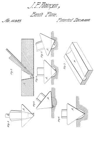
Figure 1, is an ened view of my improvement. Fig. 2, is a longitudinal verticle section of ditto, the plane of section being through the center. Figs. 3, 4, 5 are end views of my improvement in different positions showing the manner in which the grooves are formed. Fig. 6, is an end view of ditto, the form of the plane being slightly varied from those shown in the proceeding figures. Fig. 7, is a perspective view of the block of wood showing a taper groove formed by my improvement.
Similar letters of reference indicate coresponding parts in the several figures.
My invention consists in having the stock of the plane made in triangular or three sided prismatic form the cutting edge of the iron being at the junction of it’s two lower sides and shaped to correspond to the form of the sides as will be presently shown and described whereby half round and other shaped grooves of different sizes may be cut.
To enable those skilled in the art to fully understand and construct my invention, I will proceed to describe it.
A, represents the stock or body of the plane which is of triangular or three sided prismatic form.
B, represents the plane iron which passes through the center of the upper side of the plane stock, the cutting edge of the plane iron is pointed or has beveled edges corresponding with the inclination of the two lower sides of the stock as shown clearly in Fig. 1.
In Figs 1, 3, 4 and 5, the two lower sides of the stock meet at a right angle, and in Fig. 6 the angle formed by the junction of the two lower sides is acute or less than a right angle.
The width of the plane iron, B, is such that each of the lower sides of the stock will have a suitable length of cutting edge of the iron projecting through it, a suitable thwart C, being made through the stock as shown in Fig. 2.
The plane is used in the following manner: The stuff in which the groove is to be cut is marked or lined to indicate the desired width of the groove. The spaces between the marks or lines may then be chipped or roughed out a requisite depth as desired with a gouge or other instrument, or the whole of the groove may be cut with the plane, if the latter plan is preferred a shallow cut is made by the plane on each line or mark, and the edge of the plane formed by the junction of the two lower sides is placed in one of these cuts as shown in Fig. 3 and the plane operated similar to other tools of the kind. One side or edge only of the plane iron cuts in the groove and when the plane has cut one half of the groove it, the plane, will be in an upright position as shown in Fig. 4. The lower edge of the stock is then placed in the opposite cut and the other half of the groove is cut. The plane stock being of triangular form rests against the edges of the groove and determines its depth, so that if the two lower sides of the stock are at right angles to each other, the groove will be of semi-circular form, as shown in Figs. 1, 3, 4 and 5 but if the lower sides form an acute angle as shown in Fig. 6 the groove will be a semi-ellipse deeper than it is wide and if the sides form an obtuse angle the groove will be wider than it is deep.
Grooves may be made of taper form as shown at D, fig 7, and they may be made of any width and depth, the depth of course corresponding to the width and angle formed by the two lower sides of the stock.
The above implement or tool is intended chiefly for patternmakers’ use, where grooves of varying sizes require to be made.
Having thus described my invention, what I claim as new and desire to secure by Letters Patent is,
Constructing the plane stock A, of triangular or three sided prismatic form, the two lower sides forming a greater or less angle with each other and the plane iron, B, fitted in the stock as shown for the purpose set forth.
JOHN. P. ROBINSON.
Witnesses:
CHAUNCEY GREEN,
ADOLPHUS VANDEWATER.