No. 1,021,369 – Plane (Thomas A. Manley) (1912)
[paiddownloads id=”681″]1021369


UNITED STATES PATENT OFFICE.

_________________

THOMAS A. MANLEY, OF AUBURN, NEW YORK, ASSIGNOR TO OHIO TOOL COMPANY, OF AUBURN, NEW YORK, A CORPORATION OF NEW YORK.

PLANE.

_________________

1,021,369. Specification of Letters Patent. Patented Mar. 26, 1912.
Application filed January 18, 1912. Serial No. 671,879.

_________________

To all whom it may concern:

Be it known that I, THOMAS A. MANLEY, a citizen of the United States, residing at Auburn, in the county of Cayuga and State of New York, have invented certain new and useful Improvements in Planes, of which the following is a specification.

This invention relates to improvements in planes, and has for its object to provide novel, simple, convenient and effective means for adjusting the plane-frog longitudinally for facilitating the setting of the bit or plane iron in different positions in the throat of the plane body.

A further object is to provide novel and simple means for locking the frog after the same has been adjusted. And a particular object of the invention is to provide convenient and effective means for adjusting and locking the frog without disturbing the plane iron and related parts.

The various features and parts and the operation of the same, will be fully set forth in the detailed description which follows, illustrated in the accompanying drawing, and then particularly pointed out in the claims.

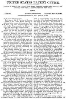
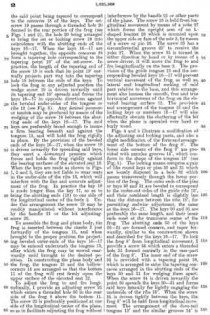
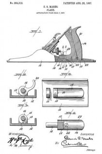
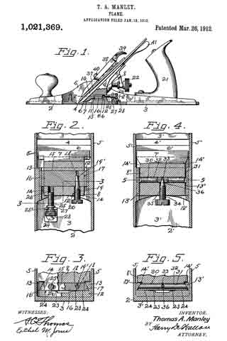
Figure 1 is a side elevation and part section of my complete plane. Fig. 2 is a horizontal section, taken on line 2–2 of Fig. 1. Fig. 3 is a vertical cross-section, taken on line 3–3 of Fig. 2. Fig. 4 is a horizontal section similar to Fig. 2; showing a modification of the locking and adjusting means. Fig. 5 is a vertical cross-section, taken on line 5–5 of Fig. 4.

Similar characters of reference designate like parts throughout the several views.

In the drawing, 2 represents the body of the plane, 3 the sole, 4 the throat or mouth, and 5 the cheeks or lateral guards which are formed integral with the body. The rear side or edge of the throat 4 is formed sharp and thin, and then the metal inclines upwardly and rearwardly at a slight angle for forming a smooth bearing surface 6 which extends across the upper side of the sole 3, to receive a correspondingly formed forwardly projecting portion 7 of the frog 8. The frog 3 consists of an irregularly shaped casting or part having a rearwardly and upwardly inclining top surface 9, for receiving and supporting the plane iron or bit 10, and having a substantially plain horizontal bottom 11, which bears and slides upon a comparatively long elevated step or portion 12, preferably an integral part of the body of the plane. The elevation or seat 12 is disposed a short distance rearwardly of the inclined bearing 6, and its top surface lies in a higher plane than the said bearing. The under side of the frog is correspondingly shaped, so that when the bottom 11 of the frog rests upon the elevation 12, the forward end 7 approaches close to the sloping surface 6. 13 represents like inwardly facing angular ribs or tongues formed horizontally on the cheek pieces 5, directly above the opposite side-edges of the elevated bearing 12, and 14 represents hollow corners or grooves formed in the opposite bottom corners of the frog, the said hollow corners preferably being formed right-angled, so as to clear the ribs 13 when the frog is moved to and fro over the body of the plane. The tongues or ribs 13 are triangular in cross-section, and preferably extend the length of the elevated bearing 12, and they are disposed parallel to said bearing, so that the frog, when operatively connected with the tongues, may be freely moved forward and backward in a true and level plane. The tongues 13 are of sufficient length and strength to effectually hold the frog from chattering while the plane is in operation.

To hold the frog 8 in place on the base 2, and yet allow said part to be freely moved to and fro for adjusting the cutting-blade or bit 10 relatively to the throat 4, the underside of the frog is provided with a broad transverse dove-tail groove or slot 15, in which is operatively fitted a pair of correspondingly shaped keys or locking members 16–17. The keys 16–17 are disposed end to end, in the slot or way 15, and their combined length is slightly less than the breadth of the bearing surface 12 beneath the tongues or guides 13, the outer ends of the keys 16–17 then project beyond each side of the bottom of the frog, as shown in Figs. 2 and 3. The outer ends of the keys 16–17 are beveled to correspond to the under-cut sides of the tongues 13 (see Fig. 3). The abutting ends of the keys 16–17 are provided with transverse concaves 18, the said concaves tapering toward the forward end of the frog.

19 represents a set-screw having a tapering point 19′ extending beyond the threads, the said point being tapered to correspond to the concaves 18 of the keys. The set-screw 19 passes through a threaded hole 20 formed in the rear portion of the frog (see Figs. 1 and 2), the hole 20 being arranged to bring the set or locking screw 19 into coincidence with the abutting ends of the keys 16–17. When the keys 16–17 are brought together, the opposite concaves 18 form a tapering hole corresponding to the tapering point 19′ of the set-screw. In practice, the length of the tapering end of the screw 19 is such that its point 19′ normally projects part way into the tapering hole 18 between the ends of the keys. To lock the frog in any adjusted position the wedge screw 19 is driven inwardly until its tapering end 19′ spreads and forces the keys 16–17 in opposite directions against the beveled under-sides of the tongues or ribs 13 (see Fig. 3). Any desired pressure or tension may be produced by means of the wedging of the screw 19 between the abutting ends of the keys 16–17. The said keys are preferably broad enough to insure a firm bearing beneath and against the tongues 13, and will hold the frog rigidly in place. By the provision of the beveled ends of the keys 16–17, when the screw 19 is driven inwardly for spreading said keys, they exert a downward pressure which forces and holds the frog rigidly against the bearing surfaces of the elevated seat 12. When the keys are made as shown in Figs. 1, 2 and 3, they are not liable to wear seats in the under-side of the ribs 13, which will interfere with the line and accurate adjustment of the frog. In practice the key 16 is made longer than the key 17, so as to bring the abutting ends (18) to one side of the longitudinal center of the body 2. Under this arrangement the screw 19 may be readily manipulated without interference by the handle 21 or the bit adjusting-screw 22.

To assemble the frog and plane body, the frog is inserted between the cheeks 5 just forwardly of the tongues 13, and when brought to the proper position the projecting beveled outer-ends of the keys 16–17 may be entered underneath the tongues 13, after which the frog may be moved rearwardly until brought to the desired position. In constructing the plane body and the frog, the tongues 13 and the hollow-corners 14 are arranged so that the bottom 11 of the frog will rest firmly upon the upper surface of the elevated seat 12.

To adjust the frog to and fro longitudinally, I provide an adjusting screw 25 which enters a threaded hole 26 in the rear side of the frog 8 above the bottom 11. The screw 25 is preferably positioned at one side of the longitudinal center of the plane, so as to facilitate adjusting the frog without interference by the handle 21 or other parts of the plane. The screw 25 is held from longitudinal movement by means of a yoke 27 which forms the upright arm of an L-shaped bracket 28 which is mounted upon the upper side or face of the sole 3, by means of a screw or pin 29. The screw 25 has a circumferential groove 25′ to receive the yoke 27. When the screw 25 is turned in either direction by hand or by means of a screw-driver, it will move the frog to and fro longitudinally on the base 2. The provision of the guide tongues 13 and the corresponding beveled keys 16–17 will prevent vertical movement of the frog, as well as, lateral and longitudinal rocking of said part relative to the base, and this arrangement also insures the smooth, free and true horizontal movement of the frog on the elevated bearing surface 12. The provision and arrangement of the tongues 13 and the locking keys or members 16–17 will also effectually obviate the chattering of the bit when the plane is operated over hard or burly wood.

Figs. 4 and 5 illustrate a modification of the adjusting and locking parts, and also a slight modification of the form and arrangement of the bottom of the frog 8′. The lower side corners of the frog 8′ are provided with annular grooves 14′, which conform to the shape of the tongues 13′ (see Fig. 5). The locking means comprise apair of like round keys or pins 30 and 31 which are loosely disposed in a hole 32 which passes transversely through the lower portion of the frog. The outer ends of the pins or keys 30 and 31 are beveled to correspond to the under-out sides of the guide ribs 13′, and their combined length is slightly less than the distance between the ribs 13′, for permitting endwise adjustment, the same as the keys 16–17. The keys 30 and 31 are preferably the same length, and their inner ends meet at the transverse center o-f the frog. The abutting ends 33 of the keys 30–31 are formed concave, and taper forwardly, similar to the construction shown and described for the keys 16–17. To lock the frog 8′ from longitudinal movement, I provide a screw 34 which enters a threaded hole 35 formed centrally in the rear-part of the frog 8′. The inner end of the screw 34 is provided with a tapering point 36, which is arranged to enter the tapering concaves arranged in the abutting ends of the keys 30 and 31 for wedging them apart. When the screw 34 is driven inwardly the point 36 spreads the keys 30–31 and forces said keys laterally for tightly engaging the underside of the ribs 13′. When the screw 34 is driven tightly between the keys, the frog 8′ will be held from longitudinal movement. The arrangement of the dove-tail tongues 13′ and the similar grooves 14′ is such that, the frog cannot be moved vertically until it is withdrawn free from the ribs. To adjust the frog 8′ to different positions longitudinally, the screw 34 is first loosened up, and then the frog may be shifted to and fro, and set in the desired position, by hand.

The plane iron or bit 10 is provided with the usual guard plate 37, and is held in place by a cap 38, which is fitted with the usual clamping part 39.

40 represents a screw carried by the frog for engaging the cap 38. The adjusting screw 22 is employed for shifting the plane iron longitudinally on the frog, and a lever 41 is employed for adjusting the plane iron laterally.

The locking means comprising the keys and the wedge screws are extremely simple, yet affording powerful means for locking the frog to the frame. When these parts are properly made and assembled, but a slight movement of the screws 19 and 34 in either direction will effect the rigid locking or the unlocking and freeing of the frog. The broad keys 16–17 cooperating with the side ribs 13 tend to steady the frog during its forward and backward movements. The disposition of the screws 19 and 25 at or near the sides of the plane render the locking and adjusting parts conveniently accessible, and in view of the location and arrangement of these parts the locking and adjusting of the frog may be accomplished without disturbing the plane-iron or any other part.

Having thus described my invention what I claim as new and desire to secure by Letters Patent, is —

1. In a plane, the combination with a sole having a throat and an elevated seat arranged rearwardly of said throat, of a frog having a plane bottom adapted to rest and slide upon said seat, said frog having longitudinal grooves formed in its opposite bottom corners, a pair of angular tongues carried by the body of the plane, said tongues received by said grooves, and adjustable means carried by said frog adapted to engage said tongues for guiding and locking said frog.

2. In a plane, the combination with a sole having a throat and an elevated seat arranged rearwardly of said throat, of a frog having a plane bottom adapted to rest and slide upon said seat, said frog having longitudinal grooves formed in its opposite bottom corners, a pair of angular tongues carried by the body of the plane, said tongues received by said grooves, adjustable means carried by said frog adapted to engage said tongues for guiding said frog, and a screw cooperating with said means for locking said frog rigidly to the elevated seat.

3. In a plane, the combination with a sole having a throat and an elevated seat arranged rearwardly of said throat, of a frog having a plane bottom adapted to rest an slide upon said seat, said frog having longitudinal grooves formed in its opposite bottom corners, a pair of angular tongues carried by the body of the plane, said tongues received by said grooves, adjustable means carried by said frog adapted to engage said tongues for guiding and locking said frog, and a swivel-screw for adjusting said frog to different positions on said sole.

4. In a plane, the combination with a sole having spaced cheek pieces and having an elevated seat between said cheek pieces, of horizontal guide-ribs formed on the inner sides of said cheek pieces above and parallel to the said seat, a frog having a plane bottom slidable upon said seat, the opposite lower corners of said frog cut away to clear said ribs, a pair of keys disposed end to end in a transverse slot formed in the bottom of said frog, said keys having their outer ends beveled to pass under and to engage said ribs, and a tapering screw for spreading said keys apart for locking the frog to said ribs.

5. In a plane, the combination of a sole having a transverse throat and an inclined bearing adjacent the throat, and having an elevated seat adjacent the inclined bearing, triangular ribs formed above and parallel to the said elevated seat, a frog having a plane bottom surface adapted to engage and slide upon said elevated seat between said ribs, said frog having portions out-away for clearing said ribs, and a pair of transversely movable keys carried by said frog adapted to engage said ribs for guiding and also for locking said frog.

6. In a plane, the combination of a frame comprising a sole and spaced cheek pieces, a raised seat formed on the sole between the cheek pieces, an inwardly facing tongue carried by each cheek piece disposed horizontally above said raised seat, said tongues having their facing sides under-cut, a frog slidable on the said raised seat between the said tongues, but free from said tongues, transversely movable keys carried by the frog having beveled outer ends adapted to slide beneath the under-out sides of said tongues for guiding said frog when moved to and fro on said seat, and a wedge-screw carried by said frog adapted to force and hold said keys against said tongues for locking said frog from movement in any direction.

7. In a plane, the combination with a body having an integral elevated seat lying between like cheeks projecting upwardly on its opposite sides, and ribs formed on the inner sides of said cheeks and overhanging said elevated seat, said ribs disposed parallel to the said elevated seat and also to the sole of the body, of a frog having a plane bottom surface adapted to engage and slide upon the said elevated seat, said frog having its opposite bottom corners. cut-away to receive said ribs, and means carried by said frog adapted to engage said ribs for holding said frog from vertical movement.

8. In a plane, the combination of a frame comprising a sole and spaced cheek pieces, a raised seat formed on the sole between the cheek pieces, an inwardly facing; tongue carried by each cheek piece disposed horizontally above said raised seat, said tongues having their facing sides under-cut, a frog slidable on the said raised seat between the said tongues, but free from said tongues, transversely movable keys carried by the frog adapted to slide beneath the under-cut sides of said tongues for guiding said frog when moved to and fro on said seat, a wedge-screw carried by said frog adapted to force and hold said keys against said tongues for locking said frog from movement in any direction, and a swivel-screw for adjusting said frog to different positions in the said frame.

9. In a plane, the combination with a body having an integral elevated seat, said body having like cheeks projecting upwardly on its opposite sides, and ribs formed on the inner sides of said cheeks and overhanging said elevated seat, said ribs disposed parallel to the said elevated seat and also to the sole of the body, of a frog having a plane bottom surface adapted to engage and slide upon the said elevated seat, said frog having its opposite bottom corners cut-away to receive said ribs, means carried by said frog adapted to engage said ribs for guiding said frog during its longitudinal movements, and means for adjusting said frog to different positions on said elevated seat.

10. In a plane, the combination of a body having vertically disposed lateral guards, ribs carried by the inner faces of said guards, said ribs arranged parallel to the sole of said body, an elevated step disposed beneath and parallel to said ribs, a frog having a substantially flat bottom adapted to rest and slide upon said elevated step, the opposite sides of said frog cut-away to clear said ribs, transversely disposed keys carried by said frog, the outer ends of said keys projecting beyond said frog adapted to engage the under-cut edges of said keys for holding said frog firmly upon said step, said keys and said ribs cooperating for guiding said frog when moved to and fro on said body, and a wedge-screw carried by said frog adapted for spreading said keys for rigidly locking said frog to the said ribs.

11. In a plane, the combination of a sole having a transverse throat and an inclined bearing adjacent the throat, and having an elevated seat adjacent the inclined bearing, triangular ribs disposed above and parallel to the said seat, a frog having a plane bottom surface adapted to engage and slide upon said seat between said ribs, a pair of keys carried by said frog adapted to engage said ribs for guiding and also for locking said frog, and a screw for adjusting said frog to different positions relative to said throat.

In testimony whereof I affix my signature in presence of two witnesses.

THOMAS A. MANLEY.

Witnesses:
G. W. BAYNON,
N. L. CASEY.

_________________

Copies of this patent may be obtained for five cents each, by addressing the “Commissioner of Patents, Washington, D. C.”
_________________

No. 864,101 – Plane (Edward S. Marks) (1907)

[paiddownloads id=”644″]864101


UNITED STATES PATENT OFFICE.

_________________
EDWARD S. MARKS, OF AUBURN, NEW YORK, ASSIGNOR TO OHIO TOOL COMPANY, OF AUBURN, NEW YORK, A CORPORATION OF NEW YORK.

PLANE.

_________________
864,101. Specification of Letters Patent. Patented Aug. 20, 1907.
Application filed March 7, 1907. Serial No. 361,030.

_________________
To all whom it may concern:

Be it known that I, EDWARD S. MARKS, a citizen of the United States, residing at Auburn, in the county of Cayuga and State of New York, have invented or discovered certain new and useful Improvements in Planes, of which the following is a specification, reference being had therein to the accompanying drawings.

This invention relates generally to bench planes and more particularly to the manner of seating the “frog”, or support for the bit or cutting iron, upon the sole or bottom of the plane. In planes of this character the frog is ordinarily made in a piece separate from the body or stock of the plane and bolted or otherwise secured thereto, and is adjustable longitudinally of the plane body in order to permit the effective size of the throat or opening in the sole of the plane to be varied. When, however, a frog of this character is adjusted to a position in which its forward or bit-supporting face lies in a plane in advance of the rear edge of the throat or opening in the sole, the lower end of the bit is left unsupported for a distance above its cutting edge equal to the thickness of the sole. In order to remedy this defect and to provide a support for the bit as near the cutting edge thereof as possible it has been proposed to provide a thinned down portion of the sole at the rear of the mouth or throat by cutting away the sole at its upper side at this point, and to provide the frog with a depending lip at its forward side which is received in the recess formed by cutting away the sole as above described, and which is adapted to support the bit at a point close to its cutting edge. It is necessary, however, in order to prevent rattling of the parts and to provide a firm support for the bit against the thrust of the plane, that the frog have a firm bearing upon the sole of the plane at a plurality of points and that it be firmly and tightly bolted or otherwise secured thereto. In the construction last referred to one of the supports of the frog upon the sole is provided by causing the depending lip on the frog to bear upon the thinned down portion of the sole at the rear of the throat. This is undesirable, since when the bolts which secure the frog to the sole are screwed down tightly the bearing of the lip of the frog upon the thinned down and therefore weakened portion of the sole tends to spring said thinned down portion out of the plane of the lower surface of the sole, thereby seriously impairing the efficiency of the plane.

One object, therefore, of my invention is to provide means for supporting a frog of the character above referred to in such a manner that the bit is supported at a point close to the cutting edge thereof while no tendency to warp any portion of the sole out of its proper plane is produced.

A further object of my invention is to dispense with the heavy raised frog seats which have been heretofore used in planes of this character, thereby simplifying the manufacture of these planes and reducing their weight.

A still further object of my invention is to improve certain details of construction in planes of this character, as will hereinafter appear.

To these ends my invention consists in certain constructions and combinations of parts hereinafter described and particularly pointed out in the claims.

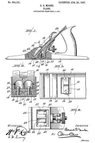
Referring to the drawings accompanying and forming part of this specification, Figure 1 is a side elevation, partly in section, of a plane made in accordance with my invention. Fig. 2 is a cross section of the plane stock and frog, taken substantially on the line 2–2, Fig. 1. Fig. 3 is a plan of a portion of the sole with the frog removed, showing the frog seat. Fig. 4 is a bottom plan view of the seating portion of the frog.

Like characters indicate like parts throughout the several views of the drawings.

12 indicates the stock or body of the plane, having a sole 13 provided with the usual throat or mouth 14, at the rear of which the sole is cut away at its upper side to provide a thinned down portion 15. Directly in the rear of said thinned down portion 15 is formed, preferably upon the sole of the plane itself, a single, continuous frog seat 16.

The frog seat 16 is adapted, alone, to support the frog, and to this end it is made of sufficient area to provide the necessary extended bearing surface to seat the frog firmly and to prevent any rocking movement thereof. The seat 16, as shown, lies wholly in a single plane substantially coincident with the upper surface of the sole, and, in the embodiment of my invention herein illustrated, is constructed in the form of a hollow rectangle, although it is obvious that many changes in the specific form of this seat might be made without departing from the spirit of my invention.

Located within and surrounded by the seat 16, and extending transversely of the sole of the plane, is a boss or rib 17. This rib is provided in order to furnish sufficient thickness of material to insure a secure engagement of the bolts 18, 18, which serve to clamp the frog 19 to its seat. To this end the boss or rib 17 is provided with threaded openings 20, for the reception of the attaching bolts 18. Preferably and as herein shown the rib 17 is provided with a transverse groove or notch 21 for the reception of a guiding or centering rib 22, on the frog 19. It will thus be seen that the boss or rib 17, provides means for engaging the attaching bolts 18, 18, and also means for guiding or preventing undue lateral movement of the frog 19, but in no other sense does the boss 17 support the frog, there being a slight clearance provided between the upper surface of the boss 17 and the opposite lower surface of the frog 19, and between the bottom of the groove 21 and the crest of the rib 22.

The frog 19 is provided with a depending lip 23, for supporting the bit 24 close to its cutting edge, and with a continuous seating portion 25, codperating with the seat 16. Surrounded by said seating portion 25 is a recess 26, for the reception of the boss 17 in the bottom of which recess is located the rib 22, and the slots 27, 27, for the passage of the attaching bolts 18, 18.

It will be noticed that a slight clearance, indicated by the numeral 28 in Fig. 1, is provided between the lower edge of the lip 23, and the thinned down portion 15 of the sole. These two parts are never allowed to come into engagement with one another, and all tendency to distort or warp this necessarily weak part of the sole is entirely prevented. The continuous frog seat 16 is oi sufficient extent to provide an absolutely firm bearing for the frog without any necessity for the frog to find an additional bearing on the thinned down portion 15 of the sole. Moreover my construction provides a wide seating area for the frog combined with a compactness of parts which is very desirable.

It will be further noticed that the frog is seated directly upon the sole, thus doing away with the heavy raised portions which have heretofore been considered necessary in order to provide the necessary bearings for the attaching screws of the frog, but which are difficult to cast satisfactorily, and which support the frog in an objectionably high position, or which have been omitted at the expense of the strength and durability of the plane. In my construction, however, the relatively small lug 17, which is not difficult to cast, provides sufficient thickness of metal to hold the attaching screws firmly, while the frog has a broad, flat, and desirably low support.

While I have shown and described one form in which my invention may be embodied, I wish it to be distinctly understood that I do not limit myself to the precise construction shown, it being obvious that many changes may be made therein without departing from the spirit of my invention.

Having thus described my invention I claim and desire to secure by Letters Patents —

1. In a plane, the combination with a sole having a frog seating surface lying in a single plane and a raised boss or rib provided with frog attaching means, of a frog having a plane seating surface adapted to cooperate with the seating surface on said sole, and cooperating means on said boss or rib and said frog for preventing relative lateral movement of said frog and sole.

2. In a plane, the combination with a sole having a single plane frog seating surface and a raised boss or rib provided with a groove, of a frog having a recess to receive said boss and a rib adapted to cooperate with said groove.

3. In a plane, the combination with a sole provided with a frog seating surface lying in a plane substantially coincident with the remainder of the upper surface of said sole and with a boss or rib rising above the plane of said frog seating surface, of a frog provided with a single seating surface adapted to coijperate with the seating surface on said sole and with a recess to receive said boss or rib, means cooporating with said boss or rib for attaching said frog to said frog seat, and coperating means on said boss or rib and said frog for preventing relative lateral movement of said frog and sole.

4. In a plane, the combination with a sole provided with a frog seating surface lying in a plane substantially coincident with the remainder of the upper surface of said sole and with a boss or rib rising above the plane of said frog seating surface, said boss or rib having a threaded aperture, of a frog provided with a single seating surface adapted to cooperate with the seating surface on said sole and with a recess to receive said boss or rib, a bolt cooperating with the aperture in said boss or rib for attaching said frog to said frog seat, and coiiperating means on said boss or rib and said frog for preventing relative lateral movement of said frog and sole.

5. In a plane, the combination with a frog having a depending lip, of a sole provided with a throat or mouth, a thinned down portion in the rear of said throat or mouth, a frog-seating surface lying in a plane substantially coincident with the remainder of the upper surface of said sole, and a boss or rib rising above the plane of said frog seating surface, means cooperating with said boss or rib for securely clamping said frog to said seat, said depending lip being out of contact with said thinned down portion, and coiiperating means on said boss or rib and said frog for preventing relative lateral movement of said frog and sole.

6. In a plane, the combination with a frog, of a sole having a throat or mouth. a frog seating surface in the rear of said mouth, and lying in a plane substantially coincident witli the remainder of the upper surface of said sole, and a boss or rib rising above the plane of said frog seating surface and provided with a frog-attaching means, and cooperating means on said boss or rib and said frog for preventing relative lateral movement of said frog and sole.

7. In a plane, the combination with a frog, of a sole having a plane frog seating surface and a raised boss or rib, and cooperating means on said boss or rib and said frog for preventing relative lateral movement of said frog and sole.

In testimony whereof I affix my signature, in presence of two witnesses.

EDWARD S. MARKS.

Witnesses:
JOHN W. BRAINARD,
RALPH R. KEELER.

No. 864,010 – Plane (Edward S. Marks) (1907)

[paiddownloads id=”643″]864010


UNITED STATES PATENT OFFICE.

_________________
EDWARD S. MARKS, OF AUBURN, NEW YORK, ASSIGNOR TO OHIO TOOL COMPANY, OF AUBURN, NEW YORK, A CORPORATION OF NEW YORK.

PLANE.

_________________
864,010. Specification of Letters Patent. Patented Aug. 20, 1907.
Application filed March 7, 1907. Serial No. 361,029.

_________________
To all whom it may concern:

Be it known that I, EDWARD S. MARKS, a citizen ofthe United States, residing at Auburn, in the county of Cayuga and State of New York, have invented or discovered certain new and useful Improvements in Planes, of which the following is a specification, reference being had therein to the accompanying drawings.

My invention relates to adjustable handles for planes.

The object of my invention is to provide a handle of the character specified which shall be simple in character, which may be easily and quickly adjusted to any desired position, and which will be securely and rigidly held in its adjusted position.

To these ends my invention, in its preferred form, comprises a handle rockingly mounted on a concave seat with which the base of the plane is provided, cooperating devices on the handle and base, which, when in engagement with one another, are adapted to hold the handle against tilting movement, and means for securely locking the handle in a position with said interlocking devices in engagement with one another.

While, as above stated, I prefer to form the handle and its seat on the base of the plane with interlocking devices I consider it to be within the scope of my invention to omit these devices and to hold the handle in its adjusted position by means of the aforesaid locking means alone, or to form these cooperating interlocking devices upon the handle and some part of the body of the plane other than the base thereof.

One construction in which my invention may be embodied is illustrated in the accompanying drawings, in which:–

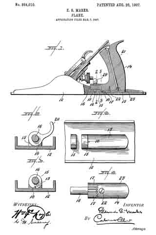
Figure 1 represents a longitudinal section through the handle portion of a plane constructed in accordance with my invention. Figs. 2 and 3 are cross-sectional views taken on the lines 2–2 and 3–3, respectively, Fig. 1. Fig. 4 is a plan view of the base of the plane shown in Fig. 1, with the handle member and clamping device removed. Fig. 5 is a bottom plan view of the handle member shown in Fig. 1.

Like characters indicate like parts throughout the several views of the drawings.

The base 12 of the plane is provided with a concave seat 13, firmly supporting the handle member 14 rockingly seated thereon, and with means for further pivotally supporting said handle member, said means as herein shown comprising a pair of upstanding, perforated lugs 15, 15, formed integral with the base 12. The handle member 14 is provided with a fixed, rigid, forwardly projecting pintle 16, adapted to enter the perforations in the lugs 15, 15, and is preferably formed with a convex under surface to cooperate with the concave seat 13.

As heretofore stated, I prefer to form the handle member and base with cooperating interlocking devices adapted to prevent rocking movement of the handle member when said devices are in engagement with one another, and to this end, in the construction shown, the handle member 14 is provided on its under surface with a plurality of’ grooves or recesses, 17, 17, while the base of the plane, at the junction of the seat 13 with the base of the rearmost lug 15, is provided with a lug 18, adapted to enter any one of the grooves 17, 17, according to the angular position of the handle member 14.

Means are provided for clamping the handle member 14, and for holding the same securely against any movement longitudinally of the plane. This means, in the construction shown, comprises an eccentric locking device 19, rotatably mounted on the pintle 16, between the lugs 15, 15. The locking device 19 is provided with a finger piece 20 by means of which it may be operated, and is adapted, when in its operative position, as shown in Fig. 2, by means of a wedging action between the base 12 and the pintle 16, to force the pintle 16 tightly against the upper sides of the perforations in the lugs, 15, 15, thereby securely holding the handle member against either longitudinal or rotary movement.

As herein shown the handle member 14 comprises a wooden handle 21, to which is permanently attached, as by a suitable screw 22, a metal shoe 23, the pintle 16, and grooves 17, 17 being formed upon said shoe 23. lt will be obvious, however, that the handle member 14, might be made in a single piece from suitable material.

In order to adjust the handle to any desired position, the finger piece 20 is raised from the position shown in Fig. 2, thereby releasing the locking device 19. The handle member 14 is then moved bodily backward until the lug 18 is clear of the groove 17, 17, after which the handle is turned into the desired position with one of the grooves 17, 17, opposite the lug 18. The handle is then moved forward into its original longitudinal position, thereby causing the lug 18 to enter the desired groove 17, and the locking device 19 again moved to locking position.

While I, in order that my invention may be more easily understood, have described the same as embodied in the particular construction shown, I wish it to be distinctly understood that I do not limit myself to this construction, it being obvious that many changes might be made therein without departing from the spirit and scope of my invention.

The concave seat 13 herein shown provides a much firmer support for the handle member than is provided in any construction of which I am aware.

Having thus described my invention I claim and desire to secure by Letters Patent:

1. In a plane, the combination with a concave handle seat, of a handle rockingly mounted thereon for angular movement transverse to the plane, and devices for retaining said handle in adjusted position.

2. In a plane, the combination with a base provided with a concave handle seat, of a handle rockingly mounted on said seat and pivotally connected to said base, and devices for retaining said handle in adjusted position.

3. In a plane, the combination with a handle mounted for angular adjustment and for longitudinal movement, of means for engaging said handle to hold the same against angular movement when in one longitudinal position, and means for locking said handle against longitudinal movement.

4. In a plane, the combination with a base provided with a curved handle seat, a locking lug, and one or more perforated lugs, of a handle member with a curved base to cooperate with said curved seat, a plurality of grooves adapted to cooperate with said locking lug, and with a forwardly projecting pintle entering said perforated lugs, and a clamping device engaging said pintle.

5. In a plane, the combination with a concave handle seat provided with a projecting lug, of a handle provided with a plurality of grooves adapted to receive said lug, and means for holding said handle with said lug in engagement with one of said grooves.

6. In a plane, a rockingly mounted handle, interlocking means on said handle and a fixed part oi the plane for holding said handle against rocking movement, said handle being bodily movable to release said interlocking means.

7. In a plane, the combination with a base provided with a concave handle seat, a locking lug, and one or more perforated lugs, of a handle member provided with a convex base, a plurality of grooves adapted to cooperate with said locking lug, and with a forwardly projecting pintle entering said perforated lugs, and a clamping device engaging said pintle.

8. In a plane, the combination with a plurality of bearing members, of a handle member having a projecting portion adapted to turn in said bearing members, and clamping means engaging said projecting portion beyond one of said bearing members.

In testimony whereof I affix my signature, in presence of two witnesses.

EDWARD S. MARKS.

Witnesses:
JOHN W. BRAINARD,
RALPH R. KEELER.

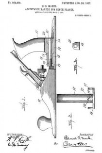
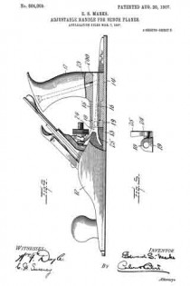
No. 864,009 – Adjustable Handle For Bench-Planes (Edward S. Marks) (1907)

[paiddownloads id=”642″]864009


UNITED STATES PATENT OFFICE.

_________________
EDWARD S. MARKS, OF AUBURN, NEW YORK, ASSIGNOR TO OHIO TOOL COMPANY, OF AUBURN, NEW YORK, A CORPORATION OF NEW YORK.

ADJUSTABLE HANDLE FOR BENCH-PLANES.

_________________
864,009. Specification of Letters Patent. Patented Aug. 20, 1907.
Application filed March 7, 1907. Serial No. 361,028.

_________________
To all whom it may concern:

Be it known that I, EDWARD S. MARKS, a citizen of the United States, residing at Auburn, in the county of Cayuga and State of New York, have invented or discovered certain new and useful Improvements in Adjustable Handles for Planes, of which the following is a specification, reference being had therein to the accompanying drawings.

My invention relates to improvements in adjustable handles for planes.

The object of my invention is to provide a reliable handle of the character specified which shall be simple in construction and which may be easily and quickly adjusted to any desired position.

To this end my invention comprises a preferably concave handle seat, a handle pivotally mounted on the body or stock of the plane and supported by said seat, and a device herein shown as a collar applied to the forwardly extending end of the handle and having a shoulder to bear against the sole of the plane, for locking the handle against tilting movement.

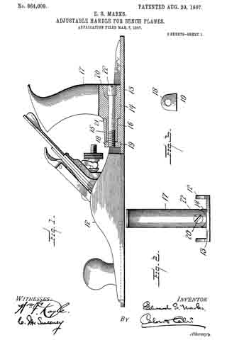
In the drawings accompanying and forming part of this specification, and illustrating a construction in which my invention may be embodied: Figure 1 is a vertical, longitudinal section of the handle portion of a plane constructed in accordance with my invention: Fig. 2 is a rear view of the same; Fig. 3 is an elevation of a collar hereinafter referred to; Fig. 4 is a view, similar to Fig. 1, of a modification. Fig. 5 is a view, similar to Fig. 3, of the collar used in the modification illustrated in Fig. 4.

Like reference characters indicate like parts throughout the several views of the drawings.

12 indicates the body or stock of the plane provided with the usual sole portion, 13. Upon the sole 13 is formed a concave handle seat 14, and an upstanding boss or lug 15 longitudinally bored to provide a bearing for a rounded, forwardly projecting portion 16 of the handle 17. The handle 17 is adapted to turn in its bearing in the boss 15, and to rock upon the seat 14 for the purposes of adjustment. Means are provided for locking the handle 17 in any desired position of adjustment, said means, as herein shown, comprising a collar 13, shown in detail in Figs. 3 and 5, having a shoulder or flattened portion 19 adapted to hear on the sole of the plane.

In the construction shown in Figs. 1 to 3, the collar 18 is formed as a nut adapted to engage the threaded end of a rod 20 passing through the handle 17, and the extension 16 thereof, and being provided at its rear end with a head 22, having means whereby said rod may be turned by means of a screw driver or other tool. The handle 17 is preferably provided with a shoulder 21, and when the rod 20 is turned to tighten the collar 18, the boss 15 will be clamped between the shoulder 21 and the collar 18, and the handle securely held against angular displacement, while the shoulder 19 on the collar 13 prevents rotation of the latter.

In the modification illustrated in Figs. at and 5 the collar 18 is provided with a smooth interior bore for the reception of an unthreaded rod 200, similar to the rod 20, but held against rotation in the handle 17 by a bolt 23. In this construction the collar 18 is tapped to receive a set screw 24, preferably provided with a finger piece 25. It will be obvious that when the set screw 24 is tightened upon the rod 200 the handle 17 will be securely held against turning or rocking movement, the shoulder 19, as heretofore stating, holding the collar 18 against rotation.

I do not limit myself to the precise constructions shown, it being obvious that many changes may be made in the details thereof without departing from the spirit or scope of my invention.

I claim:–

1. In a plane, the combination with a bearing, of a handle member having a projecting portion adapted to turn in said bearing, and clamping means engaging said projecting portion beyond said bearing.

2. In a plane, the combination with a bearing, of a handle member having a projecting portion rotatably mounted in said bearing, a collar detachably secured to said projecting portion beyond said bearing, and means for holding said collar against rotation.

3. In a plane, the combination with a sole and a bearing carried by said sole, of a handle member having a projecting portion rotatably mounted in said bearing, and a collar detachably secured to said projecting portion beyond said bearing, said collar having a shoulder engaging said sole.

4. In a plane, the combination with a sole provided with a bearing and a concave seat, of a handle member tiltingly mounted on said seat and having a projecting portion rotatably mounted in said bearing, and a collar detachably secured to said projecting portion beyond said bearing.

5. In a plane, the combination with a sole provided with a longitudinally bored boss, of a handle member seated upon said sole and having a projecting portion rotatably mounted in the bore of said boss, a rod extending longitudinally through said projecting portion, and a collar detachably secured to said rod beyond said boss.

6. In a plane, the combination with a bearing, of a handle member having a projecting portion rotatably mounted in said bearing, a collar mounted on said projecting portion beyond said bearing, and means for clamping said collar to said projecting portion.

7. In a plane, the combination with a bearing, of a handle member having a projecting portion rotatably mounted in said bearing, a rod extending longitudinally through said projecting portion, a collar mounted on said rod beyond said bearing, and a set screw in said collar engaging said rod.

8. In a plane, the combination with a bearing, of a handie member having a projecting portion rotatably mounted in said bearing, a rod extending longitudinally through said projecting portion, means for preventing rotation of said rod and said handle, a collar mounted on said rod beyond said bearing, and a set screw in said collar engaging said rod.

9. In a plane, the combination with a bearing, of a handle member, having a projecting portion rotatably mounted in said bearing, a rod extending longitudinally through said projecting portion, a collar mounted on said rod beyond said bearing, means for holding said collar against rotation, and a set screw in said collar engaging said rod.

In testimony whereof I aflix my signature, in presence of two witnesses.

EDWARD S. MARKS.

Witnesses:
JOHN W. BRAINARD,
RALPH R. KEELER.

No. 680,056 – Plane (Edward S. Marks) (1901)

[paiddownloads id=”556″]680056


UNITED STATES PATENT OFFICE.

_________________
EDWARD S. MARKS, OF AUBURN, NEW YORK,
ASSIGNOR TO OHIO TOOL COMPANY, OF NEW YORK.

PLANE.

_________________
SPECIFICATION forming part of Letters Patent No. 680,056, dated August 6, 1901.
Application filed December 10, 1900. Serial No. 39,447. (No model.)

_________________
To all whom it may concern:

Be it known that I, EDWARD S. MARKS, a citizen of the United States, and a resident of the city of Auburn, in the State of New York, have invented certain new and useful Improvements in Planes, of which the following is a specification.

This invention relates to the devices by which the chisel is adjusted in relation to the plane-stock; and it consists in certain new constructions and arrangements of the parts by which this adjustment is effected.

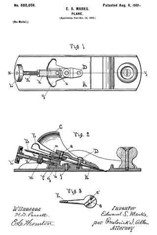
In the drawings, Figure 1 is a plan of a plane-stock provided with my improvements. Fig. 2 is a vertical section upon the line x y of Fig. 1, and Fig. 3 shows the lever separately.

Similar reference-letters indicate like parts in the several views.

In the drawings, A is the plane-stock. B is the chisel, which is secured by means of the cap C, which is held by the screw D and is locked by means of the lever E, pivoted at e and carrying a cam e’.

The foregoing parts are of usual construction.

Upon the plane-stock a carriage F is pivoted at f, which oscillates in the horizontal plane across the bed g. The carriage F is furnished with a slide h, seated thereon, and actuated by a screw K, which extends to the rear of the carriage F and is turned by its head L. A projection n upon the slide h, engages a corresponding depression or aperture m, in the chisel and holds the latter in position.

In operation the lengthwise adjustment of the chisel is performed by rotating the screw K, and by moving the carriage F upon its pivot f crosswise the lateral adjustment of the chisel is effected.

Wliat I claim as new, and desire to secure by Letters Patent, is —

In a plane and in combination; a plane-stock; a chisel mounted therein; means for clamping said chisel in said stock; a carriage pivotally mounted on said plane-stock so as to permit a lateral adjustment of said carriage and the parts supported thereby; a slide mounted on said pivoted carriage, and engaging said chisel ; and means carried by said carriage to adjust said slide and chisel longitudinally.

Signed at Auburn, New York, this 6th day of December, A. D. 1900.

EDWARD S. MARKS.

Witnesses:
H. D. PARSELL,
FREDERICK I. ALLEN.

No. 680,055 – Plane (Edward S. Marks) (1901)

[paiddownloads id=”555″]680055


UNITED STATES PATENT OFFICE.

_________________
EDWARD S. MARKS, OF AUBURN, NEW YORK,
ASSIGNOR TO OHIO TOOL COMPANY, OF NEW YORK.

PLANE.

_________________

SPECIFICATION forming part of Letters Patent No. 680,055, dated August 6, 1901.
Application filed December 4, 1900. Serial No. 38,705. (No model.)

_________________
To all whom it may concern:

Be it known that I, EDWARD S. MARKS, a citizen of the United States, and a resident of the city of Auburn, in the county of Cayuga and State of New York, have invented certain new and useful Improvements in Planes, of which the following is a specification.

This invention consists in certain new devices used to regulate the position of the chisel in relation to the plane-stock; and its object. is to furnish means for readily adjusting the chisel both longitudinally and laterally.

In the drawings, Figure 1 is a plan of a plane provided with my improvements and with the chisel and retaining-cap removed; and Fig. 2 is a sectional view upon the line x y of Fig. 1, showing the chisel and cap in position.

Similar reference-letters indicate like parts in both views.

In the drawings, A is the plane-stock, B is the chisel, and C the cap-iron, which is secured under the cross-bar D by means of the screw E.

The chisel B is provided with a rack b, and a pinion-section d, pivoted at f and operated by a lever K, engages it. The dotted lines of Fig. 2 indicate different positions which this lever may occupy in the vertical plane. By this means the chisel is moved in the direction of its length as required.

The carriage g, which supports the pivot f, is pivotally secured at h, so that it may be moved laterally, and the dotted lines of Fig. 1 show dilierent positions which it may occupy in the horizontal plane, the upright ears g’, rising from the carriage g, straddling the rack b on the under side of the chisel B and lengaging the parts for lateral adjustment, as shown in Fig. 2, the segment m upon the plane-stock furnishing a support for it in its different positions.

By the above-described means the chisel B is readily adjusted either vertically or laterally, as desired.

What I claim as new, and desire to secure by Letters Patent, is —

1. In a plane and in combination, a plane-stock, a chisel, means for clamping said chisel in said plane-stock, a carriage having a vertical pivotal connection with said plane-stock, a lever carried by and having a horizontal pivotal connection with said carriage to shift said carriage laterally on its pivot, means on said carriage to engage and shift said chisel laterally, and means on said pivoted carriage-lever to engage said chisel and shift it longitudinally.

2. In a plane and in combination, a plane-stock, a chisel, means for clamping said chisel in said plane-stock, a carriage having a vertical pivotal connection vvith said plane-stock, a segment formed on said stock to support said carriage, a lever carried by and having a horizontal pivotal connection with said carriage to shift said carriage laterally on its pivot, upright ears on said carriage to engage and shift said chisel laterally, and means on said pivoted carriage-lever to engage said chisel and shift it longitudinally.

Signed at Auburn, New York, this 1st day of December, A. D. 1900.

EDWARD S. MARKS.

Witnesses:
HENRY D. PARSELL,
FREDERICK I. ALLEN.

No. 468,362 – Carpenter’s Plane (Frank Phelps) (1892)

[paiddownloads id=”483″]468362


UNITED STATES PATENT OFFICE.

_________________
FRANK PHELPS, OF AUBURN, NEW YORK.

CARPENTER’S PLANE.

_________________
SPECIFICATION forming part of Letters Patent No. 468,362, dated February 9, 1892.
Application filed April 16, 1891. Serial No. 389,185. (No model.)

_________________
To all whom it may concern:

Be it known that I, FRANK PHELPS, a citizen of the United States, residing in the city of Auburn, county of Cayuga, State of New York, have invented a new and useful Improvement in Carpenters’ Planes, of which the following is a specification, reference being had to the accompanying drawings on one sheet, making part of this specification.

My invention relates to improvements in that class of carpenters’ cutting and surface, smoothing tools generally denominated as “planes,” the stock of which is composed of wood or similar material; and the objects are to secure in such planes the advantages of trueness and freedom from wear which obtain in planes the stock of which is made of metal and at the same time retain the advantages of lightness which pertains to planes having the stock made of wood or similar material. I attain these objects by facing the ends and the sole of the stock of said plane with suitable plates of metal in the manner illustrated in the accompanying drawings, in which —

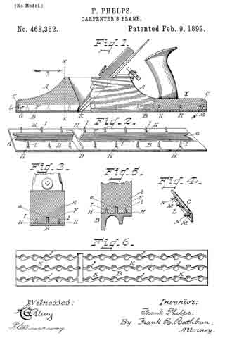
Figure 1 is a side elevation of a carpenteifs plane having a wood stock with my improvements aflixed thereto, the ends being shown in broken section, so that a clearer view may be afforded of the application of the same. Fig. 2 is a perspective view of the upper side of the metal sole-plate. Fig. 3 is a section of the stock of the plane and metal sole-plate through the line x x of Fig. 1, looking in the direction of the arrow z. Fig. 4 is a perspective view of one of the metal end plates, taken with its inner side next the point of view. Fig. 5 is an end section of a beading-plane, showing the under surface of the metal sole-plate formed for beading, but attached to the stock, as shown in Fig. 1. Fig. 6 is a plan view of the bottom side of the metal sole-plate.

Throughout the several figures similar letters refer to similar parts.

In Fig. 1 A is the wood stock of the plane. B is the metal sole-plate, and C C are the metal end plates, which are affixed thereto.

Referring to Fig. 2, the metal sole-plate B has formed therein in proper working position the transverse slot D, which corresponds to and fits when in place over the mouth E of the wood stock A.

Longitudinally and approximately in a central position on the upper surface of the metal sole-plate B is provided the flange F, which is formed at either side of the transverse slot D at proper working angles to correspond with those of the mouth E of the wood stock A. The forward and rearward ends of the flange F of the metal sole-plate B have V-shaped notches or seats G G, as seen in Fig.2, the object of which V-shaped notches will presently be explained.

Formed on the upper surface of the metal sole-plate B and constituting a part thereof are arranged at appropriate intervals between the flange F and either edge of said metal sole-plate B one or more series of vertical projections H H H, &c., which are uniformly provided near their upper ends with the barbs or notches I I I, &c., the object of which will be presently seen.

On the under surface of the metal sole-plate B are provided countersinks J J J, &c., 7 5 (see Fig. 6,) which may be regularly or irregularly arranged thereon, as desired, the said countersinks J J J, &c., being connected with each other in any desired pattern by the channels K K K, &c., the object of the said countersinks and their connecting-channels being to afford sufficient air so as to prevent any adhesion between the under surface of the metal sole~plate B and the plane surface with which it may be brought in contact.

Metal end plates C C are provided for the ends of the wood stook A of the plane, which are constructed substantially as follows: On their inner sides and forming a part thereof are formed the V-shaped projections L L in such position as will assure their engagement when adjusted to position with the V-shaped notches G G, which are formed in either end of the fiange F of the metal sole-plate B. Near either end of the inner sides of the metal end plates C C and constituting a part thereof are provided the projections M M, which are formed at right angles thereto and which are furnished with barbs or notches N N, the object of which will be presently explained. The upper ends of the metal end plates C C are turned into the segment of a circle, as shown, thus presenting a symmetrical outline and doing away with sharp and obtrusive corners.

The wood stock A of the plane has formed in a central longitudinal position of the sole thereof the groove a, the purpose of which will be presently explained.

Having thus described in detail the essential features of my invention, I will now describe their adjustment on the stock of the plane and their arrangement with relation to each other when such has been effected. The upper surface of the metal sole-plate B and the lower surface of the stock A of the plane are brought into immediate contact with each other by a compression brought to bear upon either or both powerful enough to force the several series of vertical projections H H H, &c., formed on the upper surface of the metal sole-plate B, which have been described, into the wood stock A of the plane, the fiber of which on retracting, after the said operation, engaging with and filling in beneath the barbs or notches I I I, &c., serves to assure the permanent fastening and securing together of the wood stock A and the metal sole-plate B. During this operation the flange F of the metal sole-plate B is entered in the groove a, Fig. 3, of the wood stock A, and thus serves to assure against any lateral displacement of the several parts described during and subsequent to the operation. The metal end plates C C are next brought into position on either end of the wood stock A of the plane by being forced by compression or by being driven thereon, as deemed most expedient. During this operation the V-shaped projections L L, which are formed on and project from their inner sides, engage with the V-shaped notches G G, which are formed in either end of the flange F of the metal sole-plate B and serve at the same time to bring the ends of the metal sole-plate B and the wood stock A of the plane into the closer contact and there lock them, as well as the lower ends of the said metal end pieces C C, into a joint with the ends of the metal sole-plate B, which project sufficiently beyond the ends of the wood stock A of the plane for that purpose. During this operation, also, the projections M M, which are provided on and project at right angles from the inner sides near either end of the said metal end plates C C, are forced into the wood of the wood stock A of the plane, the fiber of which, retracting, engages with and fills in behind the barbs or notches N N, formed thereon, thus substantially and permanently securing the metal end plates C C to the wood stock A of the plane and assisting, also, in the further permanent stability and securing of the ends of the metal sole-plate B, already described.

I am aware that metal plates for protecting and assuring the correctness of tools and instruments of precision, which are largely composed of wood and the said plates secured thereto in various ways, are and have for some time been in use; but I am not aware that such metal plates formed and arranged as has been described have been used in connection with carpenters’ planes or otherwise for the purpose and objects or in the manner set forth herein; therefore

What I claim as my invention, and desire to secure by Letters Patent of the United States, is —

I claim —

1. In a carpenter’s plane, the combination of a stock having a centrally-disposed longitudinal groove formed in its under surface with a metal sole-plate provided on its upper surface with a series of barbed vertical projections arranged near either side thereof, and a centrally-disposed longitudinal upwardly-projecting iiange, substantiallyin the manner and for the purpose herein described and specified.

2. In a carpenter’s plane, a stock having a centrally-disposed longitudinal groove formed in its under surface and a metal sole-plate provided on its upper surface with a series of barbed vertical projections arranged near either side thereof, a centrally-disposed longitudinal upwardly-projecting flange provided at either end with V-shaped notches, and a transverse slot D, in combination with the metal end plates provided on their inner sides with centrally-disposed V-shaped projections and near either end with barbed projections at right angles thereto, substantially in the manner and for the purpose herein specified and described.

3. In a carpenter’s plane, a stock having a centrally-disposed longitudinal groove formed in its under surface, a metal sole-plate provided on its upper surface with a series of barbed vertical projections arranged near either side thereof, a centrally-disposed longitudinal upwardly-projecting flange provided at either end with V-shaped notches, a transverse slot D, and the lower surface of said sole-plate provided with countersinks connected with each other by channels, and metal end plates provided on their inner sides with centrally-disposed V-shaped projections and near either end with barbed projections at right angles thereto, the whole combined and arranged in the manner and for the purpose herein described and specified.

In testimony whereof I have hereunto set my hand this 2d day of April, A. D. 1891.

FRANK PHELPS.

Witnesses:
JOHN J. TROWBRIDGE,
W. N. JENNINGS.

No. 174,870 – Improvement In Carpenters’ Planes (Elliot G. Storke) (1876)

[paiddownloads id=”259″]174870


UNITED STATES PATENT OFFICE.

_________________

ELLIOT G. STORKE, OF AUBURN, NEW YORK.

IMPROVEMENT IN CARPENTERS’ PLANES.

_________________

Specification forming part of Letters Patent No. 174,870, dated March 14, 1876; application filed February 7, 1876.

_________________

To all whom it may concern:

Be it known that I, ELLIOT G. STORKE, of Auburn, in the State of New York, have invented certain new and useful Improvements in Carpenters’ Planes, of which the following is a specification:

The object of my invention is to provide a simple, easy, and exact method of adjusting the bits or cutters of carpenters’ planes.

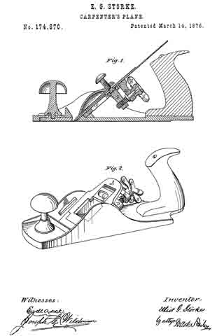
Figure 1 is a longitudinal vertical central section of an ordinary metallic plane embodying my improvements. Fig. 2 is a perspective view of the same with the bit removed.

Similar letters refer to the same parts in the respective figures.

A is the bed-plate for the support of the bit. Near the transverse center thereof is placed the sliding plate B, running in ways cut in the said bed-plate, having in its upper face an oval recess, C, for the reception of the cap screw heads of double plane-irons. From the lower face of the said sliding plate projects the shank-nut D, so far below the bed-plate that when the screw E is passed through its lower end, on a line parallel with the pitch of the plane-iron, a large thumb-wheel, F, can be mounted upon the upper end thereof without colliding with the plane-iron above or the plane-body below. That thumb-wheel is supplied with six arms, H, equally spaced upon its hub, giving as many distinct and conveniently-located levers, by which the workman can easily revolve the said wheel and move the parts with which it is connected. From the lower face of the bed-plate A, and near its upper end, projects the shank-bearing for the adjusting-screw G, of the same length as the shank-nut D, and in line therewith. Through the lower end of the said shank-bearing passes the upper end of the screw E into the hub of the said thumb-wheel, the former being shouldered where it joins the inner face of the latter, and the wheel, being pinned to the screw, carries the latter with it. Now, by revolving the thumb-wheel in the shank-bearing G, the shank-nut D and the sliding plate B are raised or lowered at pleasure, giving to the cutters a corresponding movement, and securing any desired thickness of shaving.

It will be seen from the foregoing description that my invention consists, mainly, in devices by which plane-bits are adjusted by a single direct-acting screw, operating through the medium of the cap-plates of double irons. The two shanks or lugs D and G, the screw E and sliding plate B, and the thumb-wheel F, with its arms H, are the devices employed for this purpose.

By projecting those lugs far below the bed-plate A — that is to say, far enough to carry the axis of the thumb-wheel to the center, or thereabout, of the space between the plane-iron and plane-body — I am enabled to use upon the screw E a large thumb-wheel supplied with the lever-arms H, and I thus gain all the power necessary to move the bits easily by the single screw E. The arms H, lying both to the right and left of the plane-handle, are easily and conveniently operated by the workman, either by the thumb from the left, or the fingers from the right, or both conjointly, without removing the hand — a device possessing decided conveniences over the circular thumb-screw heads heretofore in use for the same purpose.

I am aware that screws have been applied directly to plane-irons for their adjustment, but not in that way to the cap-plates of double irons, nor to their screw-heads. In the latter application the maximum movement of the operating-screw is less than one-half inch, in the former fully two and one-half inches, and a special attachment must be made to the cutter in which to work the screw; but that application, so far as I am informed, has been abandoned for the lack of power to operate the bits, and in its stead various combinations of single levers, or levers and cams operated by screws, have been resorted to, the objection to which is the increased cost of construction, and the greater liability to derangements and backlash.

I am also aware that various devices for adjusting plane-bits have been applied to the cap-plates or cap-screw heads of double plane-irons, but none, it is believed, in which that adjustment has been effected by a single screw without other intermediate devices.

The simplicity, durability, and practical efficiency of the devices herein described will, it is believed, be clearly apparent, as well as their superiority to those hitherto employed for the same purpose.

Having described my invention, I shall state my claim as follows:

The direct-acting or adjusting screw, having a thumb-wheel formed with lever-arms, as described, in combination with the bed-plate, having an elongated shank-bearing, and the sliding socket-plate, having an elongated shank-nut, all substantially as and for the purposes shown and set forth.

In testimony whereof I have hereunto signed my name this 3d day of February, A. D. 1876.

ELLIOT G. STORKE.

Witnesses:
H. L. STORKE,
LEWIS L. SMITH.

No. 173,177 – Improvement In Bench-Planes (Josef Nicht) (1876)

[paiddownloads id=”256″]173177


UNITED STATES PATENT OFFICE.

_________________

JOSEF NICHT, OF AUBURN, NEW YORK.

IMPROVEMENT IN BENCH-PLANES.

_________________

Specification forming part of Letters Patent No. 173,177, dated February 8, 1876; application filed July 29, 1875.

_________________

To all whom it may concern:

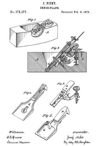
Be it known that I, JOSEF NICHT, of Auburn, in the county of Cayuga and State of New York, have invented certain new and useful Improvements in Bench-Planes; and that the following is a full, clear, and exact description of the same, reference being had to the accompanying drawings making a part of this specification, in which —

Figure 1 represents a perspective view of my improved plane, with the plane-irons and fastening-cap removed. Fig. 2 represents a longitudinal vertical section through my improved plane. Fig. 3 represents a detached view of the mechanism employed for raising or lowering the plane-irons. Fig. 4 represents a perspective view ofthe cap overlying the plane-irons, showing its under side and connected wedge. Fig. 5 represents a modification of the same.

Similar letters of reference, where they occur, denote like parts in all the figures.

My invention relates to certain combinations of mechanisms used to set or adjust plane-irons from the exterior of the plane without separating the parts, and with great expedition and accuracy.

My invention relates also to the means by which the plane-irons can be moved laterally to adjust them in that direction, and also to the means by which the plane-irons are retained in position by means of a cap and wedge.

To enable others skilled in the art to make and use my invention, I will proceed to describe the same with reference to the drawings.

A represents the wooden stock of a plane, to which is attached, by means of the screw a, the plate B, that has formed on its under side bearings b for the shaft c, around which the geared segment and lever C revolve. The rear end of this lever C is slotted, so as to fit over a pin formed on one side of the nut d, that is raised or lowered by a screw-shaft, D, having a knob or thumb-piece, D’, upon its upper end, by which it may be readily operated to raise or lower the nut d, and correspondingly the rear end of the lever C. On the front of the lever C there is a geared segment, C’, that engages with the rack E. This rack is located in a groove, b’, cut out of the plate B, so as to furnish it with the bearings required for a free and steady motion up or down. This rack E has on its upper surface a central projection, e, and another at e’, either or both of which engage with the head of a screw, f that is centrally recessed for that purpose. This screw f is otherwise the one employed to connect the plane-iron F and its iron cap F’, so that by turning the screw-shaft D the plane-irons may be moved up or down at pleasure to adjust them, and when adjusted they are firmly held in that position. G is a metallic cap overlying the plane-irons. A slot, g, is cut through it, so as to allow the head of the screw h to pass through it and rest on its upper surface. Under the rear of this cap G there is a wedge, H, by which the cap may be raised at that point and pressed against the plane-irons at or near their lower ends to clamp them together. The wedge H is retained in connection with the cap G by grooves formed on the latter, and a bolt, i, that connects the two together. To the plate B and stock A is pivoted at a a lever, k, the rear end of which projects upward, so as to be readily operated from the exterior of the plane, it terminating in a knob, k’, by which it can be moved. The inner end of this lever k is bent up, as at l, and passes into the slot ordinarily cut in plane-irons F, so that the latter can be moved laterally to adjust said irons in that direction. Thus the vertical and lateral adjustments of the plane-irons may be instantly and very accurately made.

In Fig. 5 is shown a modification of the cap G, the slot g of Fig. 4 being dispensed with, and the hook m formed in its place, so as to engage under the head of a bolt, or any similar projection attached to the stock A of the plane.

I claim as my invention —

In combination with the plane-stock A, the longitudinally-slotted plane-iron F and the mechanism composed of the screw h and cap G, carrying, secured to it, the wedge H, for clamping said plane-iron to the plane, the lever k’, pivoted to the stock of the plane, and engaging with the slot of the plane-iron to adjust it laterally, all arranged substantially as shown and described.

JOSEF NICHT.

Witnesses:
HORACE T. COOK,
W. P. BEARDSLEY.

No. 162,710 – Improvement In Carpenters’ Planes (Elliot G. Storke) (1875)

[paiddownloads id=”243″]162710


UNITED STATES PATENT OFFICE.

_________________

ELLIOT G. STORKE, OF AUBURN, NEW YORK.

IMPROVEMENT IN CARPENTERS’ PLANES.

_________________

Specification forming part of Letters Patent No. 162,710, dated April 27, 1875; application filed January 6, 1875.

_________________

To all whom it may concern:

Be it known that I, ELLIOT G. STORKE, of Auburn, New York, have invented certain new and useful Improvements in Carpenters’ Planes, of which the following is a specification:

My improvements relate to setting and fastening the bits of planes, and also to means for giving to bench-planes a metallic and adjustable throat-piece.

The nature of my invention can best be explained by reference to the accompanying drawings, in which —

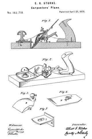
Figure 1 is a longitudinal vertical central section of a plane embodying my improvements. Fig. 2 is a perspective view of the same with the plane-iron fastener and bit removed. Fig. 3, 4, 5, are views of detached parts hereinafter described. The plane represented is one with a metal top and wooden face.

A is the lever by which the bit is set or adjusted to cut fine or coarse shavings, and Y its upward-projecting point; B, the standards which support the upper end of the bit B’; C, the journals of the said lever A, said journals resting in bearings cut in projections on the front of standards B, in which bearings the journals have a lateral or end-wise play. L L are two grooves cut on the interior opposite sides of the frame or plane-body, for the reception of lugs D’ of the plane-iron fastener D, shown in perspective in Fig. 3. The lugs are on the sides of the fastener and near its longitudinal center, and at its rear end is the thumb-screw. F is the cap and G the screw of an ordinary plane-iron, the screw-head being countersunk at at to receive the globular point Y of the lever A. s is a blank screw-hole tapped in the cap, into which the said cap-screw can be removed when it becomes necessary, by the wearing away of the wooden face of the plane, if such be used, to raise the cutting-iron.

The devices thus far described for fastening and setting the bit are operated as follows: The lever A is placed in its bearings in the standards B; the cap is screwed in the usual way upon an ordinary plane-iron, and the recess in the screw-head laid upon the point Y. When so laid the bit is upon its bearings, and the point Y fits neatly the recess a in the cap. The lugs D’ of the fastener are now placed in the grooves L L and the thumb-screw E tightened, which binds the bits to its bearings with more or less firmness, according to the pressure given by the screw.

The lugs D’ of the plane-iron fastener are introduced into the inclined grooves L L at the lower and open ends of the latter. The upper ends of said grooves are shouldered or closed, as seen in the drawing. The thick heel of the plane-iron, when drawn back, tends to force the fastener upward. This movement in time has the effect of smoothing the surfaces of contact of the lugs and grooves, thus increasing the liability of the fastener to work upward in the grooves. To remedy this difficulty l shoulder or close the grooves at their upper ends, as shown, thus preventing liability of the fastener becoming disengaged from the grooves. The long arm of the lever A is immediately under and within easy reach of the fingers of the workman, while grasping the plane-handle, and by raising or lowering it the adjustments of the bits are quickly and easily made, under the firmest pressure of the screw. I so construct the lever with a central hub bearing accurately-turned journals at its ends, with the spherical point Y rising upward from its center, and from which extends the long arm toward the plane-handle, that all its parts, being in one piece, are wrought with much greater facility, accuracy, and economy, and placed and maintained in position more easily and firmly than if separate pieces were employed in its construction, and so also that its journals have a free and accurate lateral or sidewise movement, by which the upper end of the bit, when fastened, can be so pushed to right or left as to square its cutting-edge with the face of the plane. By connecting the spherical point Y with the screw-heads of double plane-irons, I obtain not only a very cheap, but a very efficient means of adjusting them, for these screw-heads always maintain, practically, the same position, relatively to the cutting-edge of the bit, and can be countersunk at a merely nominal cost. The sweep of the long arm of the lever A carries the point Y through a sufficient arc to give the required adjustment to the bit, and a leverage of such power that the adjustment is easily made.

As this device for fastening and setting the bits of planes can be applied with equal facility to metallic planes, and to those having metallic tops and wooden faces, I provide for the wearing away of the latter by tapping the said cap a second time at s, into which, as the face of the plane wears away, the said screw can be removed, and in that way the bit can be worked higher up.

The metallic and adjustable section or throat-piece is shown detached in Fig. 5. I is the flat surface thereof, accurately milled on its sides to fit ways or guides out on each of the inner sides of the said frames or plane-body, on its upper face and immediately forward of the bit. K is the vertical portion thereof, which, when the said section is in place, projects downward to and directly in front of the bit, as seen in Fig. 1, having the same width as the latter, and its lower edge precisely in line with the face of the plane, thus forming a metallic throat-piece to keep down the grain, and to prevent wear from the friction of the shavings. To hold the said section in place a hub, M, is formed on the upper front face of the plane, so placed thereon as to enter along oval aperture, b, in said section, when the latter is in position. The said hub is tapped to receive a screw cut on the lower end of the shank of the knob N; or, if a knob be not used, the section may be held in place by a thumb or other screw, such screws having suitable washers. By driving the said screw the section is firmly held at the point desired, and loosened by a backward turn thereof. The said section is applied to an ordinary wooden plane by screwing a nut in the upper front face thereof, at the point occupied by the said hub M, as above described, and employed for the same purpose; or a plate may be formed to screw thereon, containing the hub M and the ways to guide the said section, effecting precisely the same edect in wooden planes as in those of iron, or in those with wooden faces.

As this section and throat-piece can be applied with facility and cheapness to common wooden planes and to iron planes at much less cost than the prevailing method of bedding the section in the face of the plane, its utility and importance must be manifest. No plane works well unless that part of the face in front of the bit is true and perfect, so that it will press down the wood as the bit cuts it; and in line work that pressure must be very close to the edge of the bit. Now, in wooden planes, the friction of the shavings, and of the work over which they are moved, very soon wears them away at the throat, so as to compel their frequent refacing, and supplying temporary wooden throat-pieces. My device gives to them at once a metallic throat-piece, which will permanently endure the necessary friction to which it is exposed, and also an adjustable one, by which the plane may instantly be adapted to fine or coarse work.

Having described my invention, what I claim, and desire to secure by Letters Patent, is —

1. The setting-lever, provided with journals which rest in fulcrum-bearings on the front of the plane-iron standards, and have lateral play in said bearings, substantially as shown and described.

2. The combination, with the conntersunk or recessed screw-head of a double plane-iron, of the journaled setting-lever engaging with its shorter arm the recessed screw-head, substantially as herein shown and set forth.

3. The metallic section or throatpiece applied to and movable and adjustable upon the upper face ofthe plane-body, as described, and formed with a vertical portion projecting downward through the plane body to form the front of the throat, substantially as set forth.

In testimony whereof I have hereunto signed my name this 26th day of December, A. D. 1874.

ELLIOT G. STORKE.

Witnesses:
FRED. E. STORKE,
H. L. STORKE.

No. 64,341 – Improvement In Plane-Irons (S. Markee) (1867)

[paiddownloads id=”124″]64341


United States Patent Office.


S. MARKEE, OF AUBURN, NEW YORK, ASSIGNOR TO HIMSELF AND JOHN M. EASTERLEY, OF SAME PLACE.

Letters Patent No. 64,341, dated April 30, 1867.
_________________

IMPROVEMENT IN PLANE-IRONS.

_________________

The Schedule referred to in these Letters Patent and making part of the same.

_________________

TO ALL WHOM IT MAY CONCERN:

Be it known that I, S. MARKEE, of Auburn, in the county of Cayuga, and State of New York, have invented a new and useful Improvement in Plane-Irons; and I do hereby declare that the following is a full, clear, and exact description thereof, which will enable others skilled in the art to make and use the same, reference being had to the accompanying drawings, forming a part of this specification, in which —

Figure 1 is an under side view of the plane-iron, showing the sliding-nut.

Figure 2 is a longitudinal section of the same, taken through the line x x, fig. 1.

Figure 3 is a cross-section of the same, taken through the line y y, fig. 1.

Figure 4 is a detail sectional view, taken through the line z z, fig. 2, showing the under side of the sliding-nut.

Similar letters of reference indicate like parts.

My invention has for its object to furnish an inaproved double plane-iron, simple and cheap in construction, and convenient in operation; and it consists, first, in attaching the cap to the plane-iron by a screw and sliding-nut; and, second, in the sliding-nut in combination with the plane-iron cap and screw, as hereinafter more fully described.

A is the plane-iron, which has a longitudinal slot, as shown, for the passage of the screw B, which secures the cap C to the plane-iron. The upper end of this slot is enlarged so that the nut D can he passed through it.

The cap C is made of sheet steel, slightly curved in its lower part, as shown in fig. 2. Through this cap is made a hole for the passage of the screw B. The screw B passes through the cap C and through the slot in the plane-iron A, and screws into the sliding-nut D, as shown in fig. 2. This nut is made with a projecting part or flange, as shown in figs. 2, 3, and 4, which its into the slot formed in the plane-iron A, and slides along said slot in adjusting the cap C upon the plane-iron A. By this construction it is not necessary to make the cap C as heavy as it was formerly made, when it had to be made thick enough to receive and hold the screw that held the cap and plane-iron together. This construction enables me to place the head of the screw on the upper side of the plane-irons, making it much more convenient to adjust the cap in proper position with reference to the cutting edge of the plane-iron than when the head of the connecting-screw was on the under side of the plane-iron, as was the case when the cap and plane-iron were connected together in the ordinary manner.

What I claim as new, and desire to secure hy Letters Patent, is —

The plane-iron, consisting of the slotted iron A, curved cap C, flanged sliding-nut D, and screw B, arranged and operating substantially as described for the purpose specified.

The above specification of my invention signed by me this 7th day of March, 1866.

S. MARKEE.

Witnesses:
B. J. IVES,
R. P. STOW.

No. 121,406 – Improvement In Bench-Planes (Sidney W. Palmer And Elliot G. Storke) (1871)

[paiddownloads id=”189″]121406


UNITED STATES PATENT OFFICE.

_________________

SIDNEY W. PALMER AND ELLIOT G. STORKE, OF AUBURN, NEW YORK,
ASSIGNORS TO WILLIAM J. MOSES, OF SAME PLACE.

IMPROVEMENT IN BENCH-PLANES.

_________________

Specification forming part of Letters Patent No. 121,406, dated November 28, 1871.

_________________

To all whom it may concern:

Be it known that we, SIDNEY W. PALMER and ELLIOT G. STORKE, of Auburn, in the county of Cayuga and in the State of New York, have invented certain new and useful Improvements in Bench-Planes; and do hereby declare that the following is a full, clear, and exact description thereof, reference being had to the accompanying drawing making a part of this specification, in which —

Figure 1 is a plan view of our improved plane. Fig. 2 is a vertical longitudinal section of the same on the line x x of Fig. 1, and Fig. 3 is a vertical cross-section on the line z z of Fig. 2.

Letters of like name and kind refer to like parts in each of the figures.

Our invention is an improvement in that class of bench-planes having metallic stocks; and it consists, principally, in the employment upon the lower side of the pivoted cap of a central rib extending the whole length of said cap, substantially as and for the purposes hereinafter shown. It consists, further, in a cap pivoted at or near its center transversely to the stock, substantially as and for the purpose hereinafter set forth. It consists, further, in the construction of the bearings upon which the heel of the bit rests, substantially as and for the purpose hereinafter specified. It consists, further, in the relative arrangement of the bearings for the heel of the bit with those employed for the body of the same, substantially as hereinafter shown and described. It consists, finally, in the combination of the above-named bearings with the center pivoted cap, substantially as and for the purpose hereinafter set forth.

In the annexed drawing, A represents the name or stock, provided at either side with an upward-projecting flange, B, for inclosing and supporting the cap, and having near its forward end a suitable transverse opening, C, ibr the reception ef the lower or cutting end of the bit, which opening is made variable in width by means of a plate, D, that corresponds in width to the length thereof, and sliding longitudinally within a recess formed in the face of the stock, is secured in position, when adjusted, by means of a screw which projects upward through a longitudinal slot within said stock, and is provided upon its upper end with a nut, E. Secured within or upon the upper end of the nut E is a wooden knob, E’, within which is in turn secured a metallic stud or start-pin, e, the upper end of which is considerably enlarged so as to enable it to resist a blow from a hammer when it is desired to start back the bit. Projecting vertically upward from the stock A, near its longitudinal center, is a diaphragm, F, which from the upper edges of the flanges B curves inward and upward and terminates in two lugs, f separated by means of a notch, f’, upon which, when in position, the body of the bit G rests. The notch f’ is deepened sufficiently to permit of the passage of the screw g’ of the cap G’, by which means less space vertically is required for the removal of the bit than would otherwise be the case. At a short distance in rear of the opening C are placed two other lugs, H, which correspond in width and relative transverse position with those above described, and furnish a bearing for the heel of the bit. It will be readily seen that being supported at but two points midway between its transverse center and edges the bit must invariably have a firm bearing, however unequal its thickness or uneven its heel. Pivoted to and within the upper edges of the flanges B is a cap, I, having the usual curved form and provided at and through its upper and rear end with a suitable set-screw, K. Instead of the usual transverse rib for the reception of the pivot-rod L, a longitudinal rib, M, extends through the center of the cap, and not only contains said rod, but also strengthens said cap and enables other portions ofthe same to be made much lighter than would otherwise be practicable.

By making the opening through the rib M for the passage of the pivotal rod L slightly larger than said rod the cap will be enabled to adjust itself vertically to the bit, however unequal in thickness the same may be at its lower end. Another advantage possessed by the longitudinal rib is that it not only offers no obstruction to the center of the bit, but rather furnishes a guide for the same, while in caps where the transverse rib is employed great care is required in inserting the bit to avoid hitting said rib with the same and injuring its cutting-edge.

Having thus fully set forth the nature and merits of our invention, what we claim as new is —

1. In metallic bench or other planes a pivoted cap, provided upon its lower side with a central longitudinal rib, substantially as and for the purpose specified.

2. The cap I, pivoted loosely at or near its transverse center, substantially as and for the purpose shown.

3. The arrangement of the lugs or bearings H upon the stock A, substantially as shown and for the purpose described.

4. The stock A, provided with the bearings H and f arranged substantially as and for the purpose set forth.

5. In combination with the bearings H and f and a suitable bit, the cap I, pivoted at or near its transverse center, substantially as and for the purposes specified.

In testimony that we claim the foregoing we have hereunto set our hands this 10th day of August, 1871.

ELLIOT G. STORKE.
SIDNEY W. PALMER.

Witnesses:
HORACE T. COOK,
JAY E. STORKE.

No. 108,946 – Improvement In Caps For Plane-Irons (Charles N. Tuttle) (1870)

[paiddownloads id=”173″]108946


United States Patent Office.


CHARLES N. TUTTLE, OF AUBURN, NEW YORK.

Letters Patent No. 108,946, dated November 1. 1870.
_________________

IMPROVEMENT IN CAPS FOR PLANE-IRONS.

_________________

The Schedule referred to in these Letters Patent and making part of the same.

_________________

I, CHARLES N. TUTTLE, of Auburn, Cayuga county, New York, have invented certain new and useful Improvements in Caps for Plane-Irons, of which the following is a specification.

Heretofore, in the manufacture of steel caps for plane-irons, it has been usual to forrn the raised hub that enters the elongated-slot of the cutter-iron, and that receives the confining and adjusting-screw, from the body of the cap itself, by swaging up such hub; but this is quite an expensive process, and necessitates the heating to a greater degree, and for a longer time, of the cap.

My object is to cheapen the construction of the cap and manufacture it by a simpler process; and

My invention consists in a cap having a metallic hub secured thereto by brazing, and which is afterward provided with a screw-thread, and thus forms an improved cap.

In the accompanying drawing —

Figure 1 represents, in perspective, my improved cap;
Figure 2, a. top view;
Figure 3, longitudinal central section; and
Figure 4, a longitudinal central section of a modified form.

A represents the cap of a double plane-iron, which is to be formed of steel; but, instead of swaging up a hub on the surface of the cap, I am enabled to do entirely away with such action by simply cutting off from a strip of smooth iron of proper width and thickness a length suitable for a hub, B, and this I secure to the surtitce of the cap, which I am enabled to make irom the regular rolled steel or iron, by means of brazing.

It will be evident to those skilled in the manufacture of these articles that it is a great desideratum to be able to use the regular rolled steel or iron, and have simply to cut it off the proper length, turn the corners, and round up and sharpen the Iower edge, thus obviating the heating and working of but one end.

The cap and hub are provided with a hole either after or before brazing the hub to the cap, which is provided with a thread to receive a confining and adjusting-nut, C’, which I prefer to make of malleable iron on account of cheapness and durability.

Instead of brazing the hub directly to the surface of the cap, I may punch a hole of suitable size through the cap, and in this hole place a hub of at thickness necessary to fill up such opening, and also project the proper distance above the cap to form a hub, as in fig. 4, and this hub I brazed in or to the opening in the cap.

In all cases where a hub is formed or secured to the cap by swaging, the hub has afterward to be dressed square on the sides; but with a hub previously squared in its manufacture, and then brazed, this tedious and rather expensive portion of the manufacture is avoided.

Having described my invention, I claim —

The plane-iron cap, provided with a nut when each is formed in separate pieces, and brazed together, as and for the purpose herein specified.

C. N. TUTTLE.

Witnesses:
C. W. UPHAM,
C. N. TUTTLE, Jr.

No. 96,052 – Improvement In Plane (E.G. Storke) (1869)

[paiddownloads id=”153″]96052


United States Patent Office.


E. G. STORKE, OF AUBURN, NEW YORK.

Letters Patent No. 96,052, dated October 19, 1869.
_________________

IMPROVEMENT IN PLANE.

_________________

The Schedule referred to in these Letters Patent and making part of the same.

_________________

To all whom it may concern:

Be it known that I, E. G. STORKE, of Auburn, in the county of Cayuga, and State of New York, have invented a new and useful Method of Preventing the Adhesion to the Wood, of the Faces of Metallic Planes; and I do hereby declare that the following is a full, clear, and exact description of the same, reference being had to the annexed drawing, marked “A,” making part of this specification, in which is represented the face of a metallic plane, fluted, grooved, or channelled, according to the plan of my invention.

Those flutes, grooves, or channels, may be more or less in number, and cut to a greater or less depth, provided the object be thereby attained of relieving all extra and unnecessary friction.

The object, however, is fully attained by making them about one thirty-second of an inch deep, one sixteenth of an inch broad, and one eighth of an inch asunder.

Fully one-half of the bearing-surface of the face of the plane may be thus removed, and thus to that extent diminish the points of contact, and the consequent friction, and, at the same time, preserve the full perfection of the working-face of the plane, including its throat.

It has long been known to mechanics that metallic planes have adhered to the wood much closer than wooden planes, and therefore required much more power to operate them.

This excessive friction was caused by their exact and even faces, which were not materially varied by use or atmospheric changes.

When used on very level surfaces, there were so many points of contact that the friction was troublesome, and the adhesion was further increased by atmospheric pressure, as partial vacuums would thus be formed.

The practical effect of this has been to prevent, in a large degree, the introduction and general use of metallic planes.

The object of my invention is twofold, namely, to remove about one-half of the surface of the face of the plane, so that there shall be fewer points of contact, and to form free air-channels, so that no vacuums can be formed, or any trouble arise from atmospheric pressure, however perfect the plane or true the surface on which it is moved.

I effect these two objects by fluting, grooving, or channelling the faces of metallic bench or other planes for wood-workers, as above specified, parallel to their length, or in some equivalent way.

What I claim as my invention, and desire to secure by Letters Patent, is —

A metallic plane, having the face grooved in lines parallel to the sides, in the manner and for the purpose specified.

E. G. STORKE.

Witnesses:
U. L. STORKE,
T. B. BARBER.

No. 65,604 – Improvement In Forming Projections On The Caps Of Plane-Irons (Napoleon B. Reynolds) (1867)

[paiddownloads id=”128″]65604


United States Patent Office.


NAPOLEON B. REYNOLDS, OF AUBURN, NEW YORK.

Letters Patent No. 65,604, dated December 18, 1867.
_________________

IMPROVEMENT IN FORMING PROJECTIONS ON THE CAPS OF PLANE-IRONS.

_________________

The Schedule referred to in these Letters Patent and making part of the same.

_________________

TO ALL WHOM IT MAY CONCERN:

Be it known that I, NAPOLEON B. REYNOLDS, of Auburn, in the county of Cayuga, and State of New York, have invented certain new and useful improvernents in the Manner of Making or Forming the Projection or Swell on the Cap of Plane-Irons, and which is used instead of a loose nut for holding the screw-bolt that secures the cap to the plane-iron; and that the following is a full, clear, and exact description of the manner of doing the same, reference being had to the accompanying drawings, making a part of this specification, in which —

Figure I represents at view from the back of the plane-iron, showing the slot therein and the bolt passing through it into the cap.

Figure 2 represents a cap with a hole punched through it for the reception of the button which afterwards forms the swell, projection, or nut for the screw-bolt to take into.

Figure 3 represents a section through the cap, and showing the countersinking of the hole that is to receive the button.

Figure 4 represents a section through the cap after the button or swell is fastened thereto.

Figures 5 and 6 show a top and edge view of one of the buttons before it is inserted in the hole in the cap.

Figure 6 shows the form of the swell, button, projection, or nut after it has been riveted in the hole in the cap.

Similar letters of reference, where they occur in the several separate figures, denote like parts in all the drawings.

I am aware that a swell or projection has been proposed on the cap of a plane-iron as a substitute for the ordinary loose nut heretofore used. I do not claim the swell or projection. My invention consists in the manner or means of producing this projection, which I do in a very cheap and very durable manner, without rolling down the metal or heat-welding it.

To enable others skilled in the art to make and use my invention, I will proceed to describe the same with reference to the drawings.

At manufacturing establishments where boilers are made are to be found and procured at very cheap rates, and of the very finest quality of iron, any quantity of burrs or buttons that are punched out of the plates of which the boilers are made for rnaking rivet holes. These burrs or buttons can be procured at a rate but little above that of old iron, and are therefore very cheap, whilst they have the form, body, and flange or fin that peculiarly fits them for my purpose.

The cap A I propose to make of steel, and a hole, a, having been punched through, it is then countersunk or reamed out at each side of the plate or cap, as shown more distinctly in fig. 3. I then take one of the burrs or buttons 6 and insert it in the hole a in the cap. The fin or flange c which is on the burr or button, and left there by the punch that drove it out of the boiler-plate, fits into the countersink on one side of the hole, and the burr or button projects through and beyond the other face of the cap. In this position the cap and burr are placed under a drop-die, one blow of which rivets the button or burr in the hole, and it is afterwards dressed up to the proper shape or form for entering the slot in the plane-iron, and for preventing the cap from turning on the plane-iron, whilst it can move longitudinally of it. When the riveting on of the button is accomplished, as explained, the burr or button will have assumed the form shown at fig. 7, and also in fig. 4, and be as immovably fixed thereto as though it were a part of the same metal with the cap itself.

As a matter of economy I should always use the burrs or buttons made by punching boiler-plates, yet I would regard it as my invention if these burrs were especially punched out for the purpose herein named.

Having thus fully described my invention, what I claim therein as new, and desire to secure by Letters Patent in forming a swell or projection on the cap of a plane-iron, is —

The method of construction substantially as described.

N. B. REYNOLDS.

Witnesses:
I. W. QUICK,
T. R. HUSSY.

No. 64,790 – Improvement In Bench-Planes (Nelson Palmer) (1867)

[paiddownloads id=”126″]64790


United States Patent Office.


NELSON PALMER OF AUBURN, NEW YORK, ASSIGNOR TO HIMSELF, SIDNEY W. PALMER, AND J. FOREMAN PALMER., OF SAME PLACE.

Letters Patent No. 64,790, dated May 14, 1867.
_________________

IMPROVEMENT IN BENCH-PLANES.

_________________

The Schedule referred to in these Letters Patent and making part of the same.

_________________

TO ALL WHOM IT MAY CONCERN:

Be it known that I, NELSON PALMER, of Auburn, in the county of Cayuga, and State of New York, have invented certain new and useful Improvements in Planes; and I hereby declare the following to be a full, clear, and exact description of the same, reference being had to the accompanying drawings.

My invention consists, first, in constructing an ordinary bench or other plane so that the throat or opening through which the bit projects shall be of variable size to suit the pitch of the bit and the nature of the work to be performed. In order to do this I make that part of the face of the plane in front of and bordering on the throat, adjustable or capable of being moved away from or toward the bit, according as it is desired to increase or diminish the distance between them. This arrangement is productive of important results, for the throat may be thereby so nearly closed as to cause the shaving-cut by the bit to be thrown up in an almost perpendicular direction, thus obviating the necessity of using, in connection with the bit, a cap, or, as it is sometimes called, “break-iron,” unless in exceptional cases, as, for instance, when the wood is very green and tough. In order to form a perfectly accurate bed for supporting the movable plate or section which regulates the size of the throat I resort to the expedient of running between it and the frame in which it is set, a backing of lead or other suitable material, which, when it hardens, will constitute an accurately-fitting bed supporting the plate at those points which determine its position in the face of the plane. I employ a similar expedient to form a perfect bed for the heel of the bit, as hereinafter described.

My invention farther consists in supporting the bit upon a movable bed, whose lower cud is pivoted or hinged to the frame or stock of the plane in rear of and close to the throat. The bed is capable of being depressed or elevated, its upper end moving in a circle, the centre of which is the point at which the bed is pivotcd to the stock. Its angle of inclination with respect to the throat may thus be varied at pleasure, and the bit which it supports may consequently be adjusted to any desired pitch.

Another feature of my invention is the construction and arrangement of the mechanisms for holding the bit in position on the bed, and for adjusting and maintaining it in and to its proper relations with the threat and face of the plane, i. e., for regulating its “cut” or the distance it shall project out from the throat, and for keeping or preserving its parallelism with the face of the plane. These various devices are all attached to and secured in the bed, and are actuated and operated in the manner hereinafter described.

My invention also consists in supporting the heel or lower part of the bit against a solid bed or backing of metal or other suitable material of suffiicient hardness, formed between it and the back of the throat. The object I have in view is to make a bearing or backing for the bit at the point where the strain mostly comes, when the plane is in use. By placing an accurately-fitting bed between the back of the throat and the heel I am enabled to accomplish this object. When the bit is secured in position on the movable bed, its lower end is pressed firmly and solidly against the backing, effectually checking and preventing any and all vibration ofthe bit, a defect to which ordinary planes are very liable, as is well known.

Lastly, my invention consists in the construction and arrangement of a detachable and independent cap or “break-iron” for turning or bending the shavings up out of the way, which may be secured to or removed from the bit with facility. It is further made adjustable by connecting the two pieces of which it is composed, by means of eccentrics, which may be operated by a lever or equivalent device, so as to adjust the blade or lower end of the cap in its proper position on the bit.

Having thus described the general features of my invention, I will now proceed to detail more particularly the manner in which it is or may be carried into effect by reference to the drawings, in which —

Figure 1 represents a longitudinal vertical section of a plane constructed in accordance with my invention;

Figure 2 is a plan view of the same.

Figure 3 is a like view with the cap and bit removed so as to show the construction and arrangement of the tilting or movable bed.

Figure 4 is a longitudinal vertical section of a plane in which a modification of my invention is shown; and

Figures 5, 6, and T are views of detached parts.

The mechanism for increasing and lessening the size of the throat consists of a movable and adjustable plate, C, which is placed in the front part of the plane, so as to be flush with and form part of the face. It is supported and held in proper position to the face of the plane by a backing or accurately-fitted bed of suitable material formed between it and the stock, as above explained. Just in rear of it is the slot or opening which constitutes the throat of the plane. The plate is capable of sliding longitudinally in the stock, its motion being limited and controlled by at stem, c, attached to its upper side, which extends up through at slot, g, formed in the top of the frame A. Upon the stem c is cut a screw-thread, so that it may engage with the hollow shank b: of the knob I, which is screwed down upon that part of the stem e projecting above the surface of the stock. It will be seen that the plate may thus be moved so as to close or open the throat, being held in any desired position by the shank b, which, when the plate is properly adjusted in relation to the hit, is screwed down tightly ever the male stem c, and maintains the whole device firmly in position. The plate is let into the stock, which thus forms in frame in which it is set so as to be flush with the surrounding face of the plane. The plane itself is what is known as a metallic plane, its stock or frame being cast iron. The movable or tilting bed G, which supports the bit, is pivoted or hinged at its lower end to the cast-iron stock a little in rear of the throat. Its pivotal points y’ constitute the axis upon which it is moved for the adjustment of the bit to its proper pitch.

As shown in the drawings, it consists of at skeleton frame which carries the mechanism for adjusting the bit, both as to the extent to which its cutting edge shall project from the throat, and as to its lateral inclination in order to maintain the parallelism of its edge with the face of the plane, and also for regulating its pitch and locking or fastening it in place. These different mechanisms I will now proceed to describe in detail:

First. The devices for adjusting the “cut” of the bit or its verticlal adjustment. The skeleton-frame G contains in its upper part an interior circular frame, G’, which is recessed so as to receive a, rotary disk, K. This disk is of somewhat less size than the recess, and has a groove formed in its periphery. The space between it and the annular frame G’ is filled with an anti-friction metal x, which enters the groove formed in the disk, and thus holds it in position, being itself retained in place by the V shape given the interior surface of the surrounding frame G’. Other methods, however, of holding the rotary disk K in its annular frame will readily suggest themselves, and nmy be used with perhaps equally good effect. The disk carries an eccentric-pin, y, to which is attached a plate, L, which extends downward some distance on the front of the bed, and has a. projecting tooth, i, formed on its face and, near its lower end. The tooth engages with an rack, h, attached to or formed on the under side of the bit B, and by this means, whatever movement is given the plate L, by reason of its eccentric connection with the rotary disk, is imparted to the bit. The toothed plate slides between guides m, which prevent it from moving in other than a longitudinal direction.

This mechanism operates in the following manner: When the bit B is in position on the bed G, and it is desired to adjust its cutting edge so that it shall project more or less from the face of the plane, the disk K is rotated by means of a lever-arm, E, rigidly connected therewith. This rotation of the disk causes, of course, a change in the position of the eccentric-pin y, which is raised or lowered according as the lever E is moved to the right or left. The movement of the pin y is communicated to its plate L, which is raised or lowered in a corresponding degree. The bit B is made to follow the motion of the toothed plate by means of the tooth i, which engages with the rack h, and draws with it the bit as it is moved up and down. Therefore, by simply moving the lever E or other equivalent device for rotating the disk, the bit may be set or adjusted vertically with great ease, and with perfect accuracy and nicety.

Second. The mechanism for adjusting the cutting edge of the bit, so as to maintain its parallelism with the face of the plane. About midway between the two ends of the bed G is it transverse sliding bar, D. This bar extends across the bed, in which are formed recesses or guides to receive it. It is capable of a sliding motion transverse to the length of the bed, and is held in place by the lower and smaller end m’ of the plate L which laps over and holds it against the bed. The end m’ lies between two jaws l l projecting from the face of the sliding bar, the distance between which is sufiicient to prevent their interference with the arm or plate L, when the bar D is moved to and fro. The jaws, when the bit is in place, embrace or grasp the rack h and draw it, and consequently the bit with them, when the bar to which they are attached slides in one direction or the other. In order to accommodate itself to this movement the bit is made capable of at little play between the sides of the stock, so that when its upper part is moved in either direction the lower end will be tilted or laterally inclined in a corresponding degree, and thus throw forward one side or the other of the cutting edge, as desired.

The transverse motion is given to the sliding ber D by providing it with at short arm or spur f, which extends back from the bar in such manner as to fit in a spiral or cam-groove, p, formed in the face of a shaft, k, which is supported in suitable bearings on the under side of the bed G. Upon one of the ends of this shaft a lever-arm, S, is secured by means of which the shaft may be rocked or rotated. When the lever S is moved up or down it will induce the rotation of the shaft, which in turn will, through the medium of the cam groove p and spur f, cause the bar D to slide from right to left, or vice versa, according as it is desired to advance one end or the other of the cutting edge of the bit. By this means the edge may be always kept parallel with the face of the plane, being adjusted to and in such position with the greatest accuracy and precision.

The bit and bed are locked or bound together and held in proper operative position by means of a toggle-jointed lever, H N. The lever N, which is nearest the bed, is forked at one end, fitting on the respective journals of the cam-shaft k. The other arm, II, of the lever terminates in a point, which fits in a corresponding cup or depression formed in the heed of a thumb-screw, P, which is secured to the handle of the plane so as to face the bed. A lever-handle, e, which extends upward from the arm H, is the means by which the lever is operated, and the joint either bent or straightened, as required. When the bit is placed on the bed, and it is desired to secure them in place, the lower end of the arm H is placed in the depression in the head of the thumb-screw P.

The lever e is then pressed forward, which causes the straightening of the toggle-joint, the other arm N of the lever forcing the bed and superincumbent bit up against pins a a, secured at the proper height in the sides of the stock. The bit and bed are thus held firmly between the straightened lever and the pins, which prevent their further motion in either direction. When the bit is to be removed, the toggle-joint must of course be bent by pressing back the lever e, after which the bed can be drawn down far enough to allow the bit to be withdrawn.

If, however, it is only desired to adjust the edge of the bit properly to the face of the plane, the bit need not be loosened. It may still be moved under the pins a a, which bind it down to the bed to a limited degree, by means of the levers S and E, which regulate its position with regard to the throat and face of the plane, as above explained. The pins a can be placed at any height in the stock to give the required pitch to the bit, and the thumb-screw P can be screwed in or out to adjust the bearing of the toggle-jointed lever. If a very steep pitch be required for the bit, as in a veneering or like plane, the lever H can be reversed so that its longer arm H’ may take its place and support the bed in a more elevated position.

To give an additional support to the heel of the bit I place between it and the rear of the throat a stationary bed, d, forming a, solid backing, against which the heel bears firmly, thus preventing the vibration of the bit when the plane is used. It is important that this backing should accurately fit the bit, and I have found that the best method of accomplishing this is to run between the heel and the back of the throat molten lead or other suitable metal, or any plastic material that will harden, so as to form at sufliciently firm and solid bearing for the heel of the bit.

In connection with the bit and bed thus constructed and arranged, I use it cap or “break-iron,” which is not attached to the bit, and which can be removed from or adjusted to the mouth of the plane with great facility. The cap is composed of two section or pieces F F’, as shown in the drawings. They are so placed in relation to each other that their contiguous edges overlap. The upper piece F’ is recessed so as to receive the projecting arm o of the lower section F. A rod or disk which binds the two parts of the cap together is inserted through the arm o, its other end being supported in a bracket or pending arm extending from the upper part of the piece F’. The two ends u v of this cylindrical disk are eccentric with respect to each other, and the disk itself, like the disk K above mentioned, is capable of being rotated by at lever, r, which projects through at segmental slot, s, in the upper piece F’. By means of this eccentric connection between the two plates F F’ I am enabled to move them toward or away from each other, as desired. The lower plate F has secured to it the blade or “break-iron” proper, M, which is held by screws w fitting in slots w’ formed in the lower portion of the piece F. The length ofthe blade M may thus be regulated. The cap, as will be seen by reference to the drawings, is placed on top of the bit. It is held in its proper relations to the edge of the bit and to the throat by means of a set-screw, t, in its upper end, which when screwed down will force the cap up until it meets the pins n, which like the pins a project from the side of the stock, and also fit in recesses formed in the upper plate F’ for their reception. The esp can thus be held firmly in place. Its accurate adjustment to the bit is effected through the medium ofthe lever r, which when moved will cause the lower part F of the cap to slide up or down, as it is required to increase or lessen the distance between its edge and the edge of the bit. As before said, by means of the movable plate C I am enabled to dispense with the use of a cap, unless when the wood is very green and tough; and for this reason, in feet, the cap is made so as to be easily attached to or removed from the plane.

My invention is capable of being modified in many particulars, as shown in fig. 4; for instance, where the movable bed G, unprovided in this case with the various mechanisms which I have just described, is supported and held in place by curved and slotted arms A’ A’, which overlap each other, one attached to the stock, the other to the bed, and both being held together by a set-screw passing through the slots, which, when loosened, allows the pitch of the bed to be adjusted, and when tightened holds the two arms together in my desired position. The bit may be either pressed against the bed by pins a a and levers, as shown in fig. 1, or it may be held in place by a set-screw, or by other suitable means. The defferent mechanisms which I have described may also be varied in memy respects without departing from the principle of my invention.

Having therefore described my invention, and the manner in which it is or may be carried into effect, what I claim, and desire to secure by Letters Patent, is —

1. The combination, with the movable section or plate for adjusting the size of the throat, of a recessed bed and frame formed in the plane-stock in front of the bit, and parallel to the face of the plane, so as to enclose the said section on three sides and form the ways in which it slides for purposes of adjustment, substantially as shown and set forth.

2. The bed for supporting the heel of the bit, formed of lead or other suitable plastic material, as specified, run between the said heel and the back of the throat, so as to form an accurately-fitting and solid bed for bit close to its cutting edge, substantially as herein set forth.

3. The method of and means herein described for adjusting the bit longitudinally, so that it shall project more or less from the face of the plane, that is to say, connecting the bit with an eccentric mounted in the bed of the bit, the eccentric being operated substantially as herein shown and set forth.

4. I claim the mechanism for maintaining the parallelism of the edge of the bit with the face of the plane, the same consisting of the combination, with the bit and bed in which it is supported, of a bar capable of sliding laterally in the bed, as described, and connected with the bit under such an arrangement that it shall cause the edge of the bit to be tilted or inclined toward one side or the other, substantially as set forth.

5. The combination of the transverse sliding bar, provided with jaws and projecting arm or spur, as described, with a cam or spiral grooved shaft and actuating lever or equivalent means, substantially as herein shown and set forth.

6. The combination, with the tilting or movable bed and bit which it supports, of the toggle-jointed and reversible lever, and holding-pins in the sides of the stock, substantially as herein shown and described.

7. The combination, with the movable bed and toggle-jointed lever, of an adjustable bearing for the said lever, substantially as set forth and described.

8. I claim the adjustable cap herein described, the some consisting of an upper and a lower plate or section connected by an eccentric rod or disk, whereby the lower section may be adjusted in its proper relation to the cutting edge of the bit, substantially as shown and set forth.

9. I claim the combination, with the movable section for adjusting the size of the throat, of the knob for securing the same under the arrangement herein described, so that the said knob shall not only serve to adjust and hold the said section in place, but shall also be a handle for guiding the movement of the plane, substantially as set forth.

In testimony whereof I have signed my name to this specification before two subscribing witnesses.

NELSON PALMER.

Witnesses :
HORACE T. COOK,
J. J. SHEPHERD.

No. 16,569 – Joiner’s Plane (J.F. Palmer) (1857)

[paiddownloads id=”36″]16569


UNITED STATES PATENT OFFICE.

_________________

J. F. PALMER, OF AUBURN, NEW YORK, ASSIGNOR TO S. W. PALMER, OF DETROIT, MICHIGAN.

JOINER’S PLANE.

_________________

Specification of Letters Patent No. 16,569, dated February 3, 1857.

_________________

To all whom it may concern:

Be it known that I, J. F. PALMER, of Auburn, in the county of Cayuga and State of New York, have invented a. new and useful Improvement in Joiners’ Planes; and I do hereby declare that the following is a full, clear, and exact description of the same, reference being had to the annexed drawing, making a part of this specification, said drawing being a longitudinal vertical section of my improvement.

My invention consists in the peculiar means employed for adjusting the plane iron, as will be hereinafter fully shown and described, whereby the plane iron may be set with the greatest facility and also be raised free from the work as the plane is drawn back so that the cutting edge of the iron is not impaired thereby.

To enable those skilled in the art to fully understand and construct my invention, I will proceed to describe it.

A represents the plane stock which is constructed of wood and in the usual manner. B is the opening or throat in the plane, and C is a metal plate which is screwed to the back side of the opening or throat, the lower edge of the said plate being beveled and made flush with the bottom or face of the stock. The upper end of the plate is also flush with the upper surface of the stock. The plate C has an oblong recess (a) made in it to receive a spiral spring (b) and also has four guide slots made in it to receive pins (d) which are attached to the back of a plate D which is fitted over the plate C, the plate D being a trifle shorter than the plate C. The plate D has a projection or lip (e) on its back side, said projection or lip fitting over the spring (b) in the recess (a) of the plate C. The projection or lip (e) is notched, or it may be formed of two parts to allow a screw rod E to pass through it. The upper end of the screw rod has a small thumb wheel (f) upon it, and a groove or recess (g) is made circumferentially in the upper part of said rod to receive a fork (h) which is attached to the back side of the plane iron E’. The lower part of the screw rod has a nut F upon it which leans upon the projection or lip (e) on the plate D, and this nut has a screw (i)attached to it, said screw passing through a hole (j) in the plate D, and through a slot (j’) in the plane iron E’, and having a thumb nut (k) on its outer end. The lower part of the plane iron E’ has a cover iron G attached to it.

The upper edge of the nut F is beveled as plainly shown in the drawing, and a rod H is fitted longitudinally in the stock A, said rod having a vertical plate I attached to its back end, the plate I being at the back side of the tote or handle J. The front end of the rod H has a fork (l) formed on it, and when the rod H is pressed forward, it passes through an opening in the plate C and bears upon the upper nut F — a spiral spring (m) is placed upon the rod H, said spring keeping the fork free from the nut F.

From the above description will be seen that by turning the screw rod E, the plane iron E’ may be raised or lowered so as to give it the required “set,” and the plane iron is firmly secured in position or prevented from turning casually. The plate D is connected with the plate C by a guide pin so as to regulate the length of vibration of the plate D and plane iron E’, which are forced downward as the plane is shoved forward by pressing the palm of the hand against the plate I, the rod H being shoved forward thereby and the fork (l) bearing or pressing down the nut F, and consequently the plate D and plane iron E’, said plate and plane iron being kept up above the work or board being planed by means of the spring (b).

By the above improvement the plane iron may not only be set with facility but it is kept up from the work as the plane is drawn backward and consequently the cutting edge of the iron E’ is prevented from being rounded and rendered dull. The plane irons of ordinary planes are soon deprived of their sharp edges in consequence of being drawn backward over the work.

Having thus described my invention, what I claim as new and desire to secure by Letters Patent, is,

The two plates C, D, and plane iron E’ arranged relatively with each other as shown and used in connection with the screw rod E, and rod H as herein described and for purpose set forth.

J. F. PALMER.

Witnesses:
HORACE T. COOK,
C. H. JENKIN.