No. 136,469 – Improvement In Carpenters’ Planes (Justus A. Traut) (1873)

[paiddownloads id=”208″]136469


UNITED STATES PATENT OFFICE.

_________________

JUSTUS A. TRAUT, OF NEW BRITAIN, CONNECTICUT.

IMPROVEMENT IN CARPENTERS’ PLANES.

_________________

Specification forming part of Letters Patent No. 136,469, dated March 4, 1873.

_________________

To all whom it may concern:

Be it known that I, JUSTUS A. TRAUT, of New Britain, county of Hartfbrd and State of Connecticut, have invented certain new and useful Improvement in Carpenters’ Planes; and to enable others skilled in the art to make and use the same I will proceed to describe, referring to the drawing, in which the same letters indicate like parts in each of the figures.

The nature of this invention consists in making a metal tool combining plow, dado, and rabbet, capable of being easily and quickly changed and adjusted from one to the other.

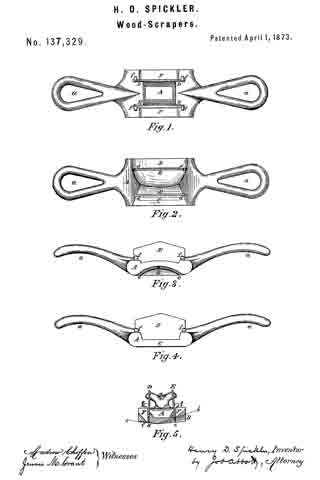
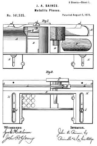
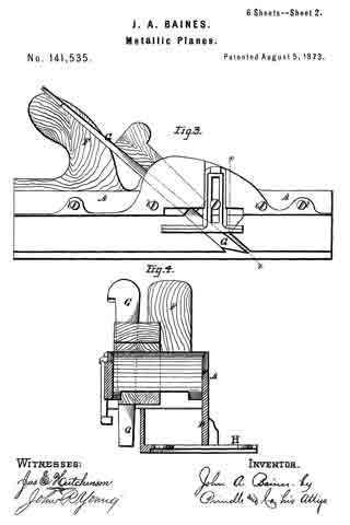
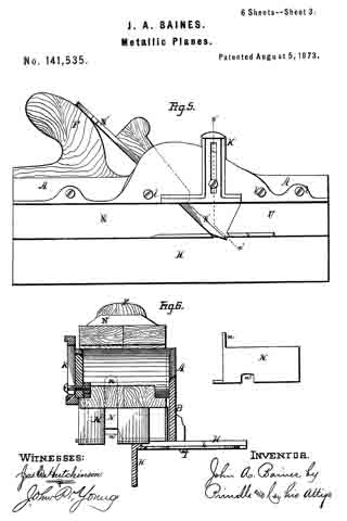
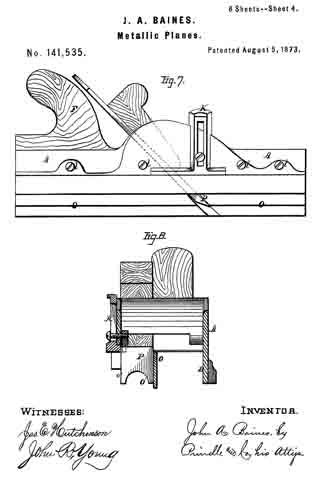
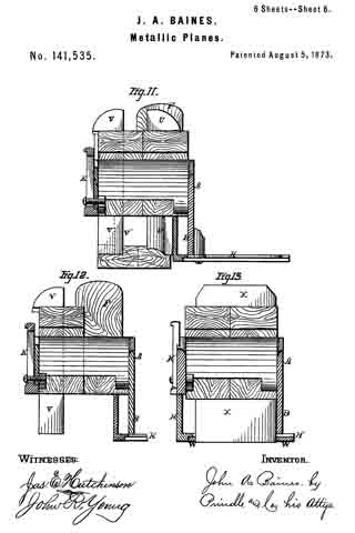
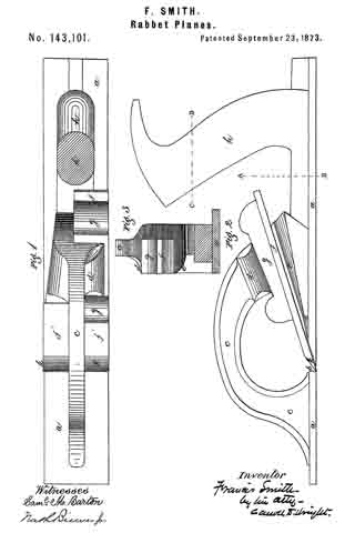
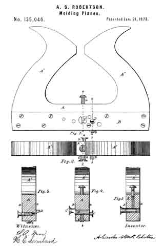
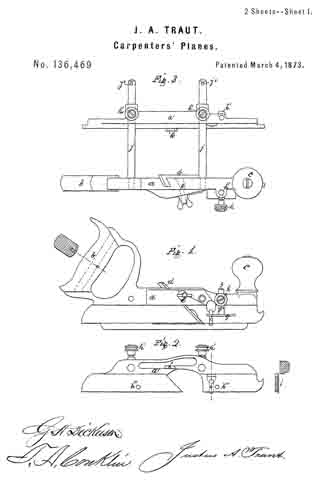
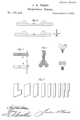
Figure 1 is an outside elevation of the stock, in which the cutting-tools are secured. Fig. 2 is an inside view of an adjustable section of the stock, which is fitted closely and works back and forth freely upon arms, which are secured in a detachable manner into the main stock. Fig. 3 is a top view of this tool, showing the detachable arms secured in the body of the stock, one portion of which is arranged thereon so as to move back and forth freely and parallel with the main body. Fig. 4 shows the sides and section of a guide-plate, having a rabbet on each side which takes bearing on the edge of and is secured to the outside of the adjustable section of the stock by screws; one side of this plate when secured will be flush with the inside face of the stock; when the other side of the plate is secured to the stock it will form a rabbet at the junction of the lower edge of the stock and face of the plate; when secured flush with the stock serves simply as a guide; when secured so as to form a rabbet, the lower edge of the stock and face ofthe plate will take bearing against the edge and surface of the material being worked. Fig. 5 is a gage device, arranged near the front end of the tool to regulate the depth of cut, adjusted and held at the desired point by a set-screw. Fig. 6 is a screw-bolt, fitted into a hole drilled through the stock to receive said bolt, and is couuterbored from the inside so as to just receive the head of said bolt; one side of said bolt-head is cutaway so as to form an incline plane parallel with the face of the cutting-tool, so that by turning the nut on said bolt the incline surface will compress the cutting-tool and hold it firmly in its place. Fig. 7 are cutting-tools much like those in common use.

a is the stock proper. a’ is an adjustable section of the stock. b is a handle, fitted and secured to the metal by glue, having an admixture of mineral or other suitable material to insure its being held more firmly; I also insert a rivet through the wood and metal. c is a knob, arranged at the front end of the stock a, by which to steady the tool. d is the cutting-tool, fitted to the stock in the usual way, and is pressed to its seat by the incline surface of the screw-bolt e. f is a gage to regulate the depth of the cut of the tool d, having a shoe, g, secured to an arm, g’, by which it is adjusted and held to its desired position by set-screw h. This gage f is fitted to the sockets h’ h’ in the two-part stock, so that it can be changed from one to the other as occasion may require. i i are spur-cutters, fitted into dovetail grooves in the outside surfaces, and near the lower edge of the two parts of the stock a a’, just in front of the cutters, for the purpose of cutting the fiber of the wood to prevent the cutter from tearing. j j are arms fitted into the body of the stock, so that they may be removed and replaced at pleasure simply by inserting a pin into the orifices j’ The adjustable section of the stock a’ is attached to the arms j j, to fit closely and move freely to and fro in its relative position with the stock a, and is secured by set-screws h h. k is a boss or projection formed on the inside of the adjustable section a’, Fig. 2, so that when a cutter is secured in the stock a, and the adjustable stock a’ is moved forward, the boss k will bear against the outer edge of the cutter, which will fix the spurs the exact distance apart as the cut of the tool, thus forming a dado variable in width with that of the cutter used, simply by changing one cutting-tool for another.

If it be desirable to use a rabbet-plane place the side m of the guard-plate n against the outside and lower edge of the plate of the stock a’, and secure it by the screws h”’ h”’, Fig. 2, which will allow the lower edges of the two-part stock a a’ to rest upon the surface of the material, while the face of the guard-plate it bears against the edge or sides of the material on which the rabbet is to be formed. Thus a perfect rabbet-plane is produced susceptible of being regulated to various widths and depth.

When it is desirable to use this tool for a plow place the side m’ of the guard-plate n against the stock-plate a’, flush with the inside thereof, and secure the same by set-screws h”’ h”’; then use in the common way. Thus I am enabled to produce a dado, plow, and rabbet-plane in one tool, quickly and easily changed from one to the other, made detachable, and which can be packed in a small compass.

What I claim, and desire to secure by Letters Patent, is —

1. The combination of the stationary stock a with the adjustable stock a’, when the latter is provided with the boss k, substantially as and for the purpose specified.

2. The detachable and reversible guard-plate n, when used in combination with the stock a, and adjustable stock a’, substantially as and for the purposes specified.

JUSTUS A. TRAUT.

Witnesses:
G. H. DICKERSON,
J. A. CONKLIN.

No. 137,329 – Improvement In Wood-Scrapers (Henry D. Spickler) (1873)

[paiddownloads id=”209″]137329


UNITED STATES PATENT OFFICE.

_________________

HENRY D. SPICKLER, OF CANTON, OHIO.

IMPROVEMENT IN WOOD-SCRAPERS.

_________________

Specification forming part of Letters Patent No. 137,329, dated April 1, 1873; application filed December 5, 1892.

_________________

To all whom it may concern:

Be it known that I, HENRY D. SPICKLER, of Canton, in the county of Stark and State of Ohio, have invented certain new and useful Improvements in Wood- Scrapers; and that the following is a full, clear, and exact specification thereof, which will enable others skilled in the art to make and use the said invention.

My invention relates to the construction of a tool for scraping and smoothing the surface of wooden implements, such, for instance, as ax-handles, spokes, &c., after they have been worked into the desired shape by means of a lathe or other machinery for accomplishing that object. It consists of a metal frame, having a handle cast or otherwise attached at each end, and having two longitudinal slots, in which are secured knives with scraping-edges, one of a straight and the other of a curved form, which are arranged at such an angle with the bottom faces of the frame, and with their edges at such distances from said bottom faces, as to cause the said knives to act as scrapers on the article to be operated on, when the tool is drawn over said article after the manner of using the ordinary spoke-shave. This scraper is applicable to nearly all the uses to which the common plate scraper is applied, while it is much easier to operate and does better work than the common scraper.

In the accompanying drawing, Figure 1 is a top view of the scraper; Fig. 2, a bottom view of the same 5 Fig. 3, a view of that side of the scraper used for curved surfaces; Fig. 4, a view of the side used for straight surfaces; and Fig. 5, a vertical cross-section of the same.

A is the metal frame, having handles a a cast on it. D and E are knives inserted in slots F F, and having their edges d and e turned forward, like the ordinary scraper, the knife E having a curved lower edge, e, while the edge d of the knife D is straight. The knives D E are held firmly in place by means of the wedges f f driven into holes in the frame, the edges of said knives projecting slightly below the bottom-faces B C of the frame. The slots F F in which the knives are placed are made of a triangular section, to receive the scrapings thrown up by the knives. The base of the frame A is inclined from the middle toward the sides, as shown at B and C, Figs. 2 and 5, the face being also curved longitudinally, to correspond to the shape of the knife E, and adapt it to use on curved surfaces. On applying either knife to a wooden surface, the inclination of the base inclines the knife, so that the angle D d c or E e b formed by the knife with the surface toward whichit is moving will be less than a right angle, the acuteness of the angle depending on the amount of inclination of the base, by which means the scraping or turned-up edges d e of the knives are brought at the proper angle to act on the wood, as will be readily seen.

In using the scraper, the operator draws the tool over the wood with the knife d forward, when he wishes to use the straight cutting-edge, and in the opposite direction when the curved edge e is desired, only one cutting edge being in operation at one time, as will be seen from the form of the cross-section shown in Fig. 5.

I lay no claim to a scraper constructed with a single scraping-knife, as such device has been heretofore shown in Letters Patent granted to F. A., J. H., and D. C. Williams, July 24, 1866, No. 56,651, and I confine my claim to a double scraper, having a straight knife on one side and a curved knife on the other, as herein shown.

What I claim as my invention, and desire to secure by Letters Patent, is —

The double scraper herein described, consisting of a frame, A, with handles a a, in which are secured two knives, D E, with turned or scraping edges d e, said knives being arranged back to back, and on opposite sides of the frame A, and one of said knives, D, having a straight, and the other knife, E, a curved edge, substantially as and for the purpose specified.

As evidence of the foregoing, witness my hand this 4th day of November, A. D. 1872.

HENRY D. SPICKLER.

Witnesses:
JOB ABBOTT,
JENNIE M. GRANT.

No. 138,591 – Improvement In Planes (J. Ceville Spencer) (1873)

[paiddownloads id=”210″]138591


UNITED STATES PATENT OFFICE.

_________________

J. CEVILLE SPENCER, OF PHELPS, NEW YORK, ASSIGNOR TO HIMSELF
AND FRANCIS X. GERVIS, OF SAME PLACE.

IMPROVEMENT IN PLANES.

_________________

Specification forming part of Letters Patent No. 138,591, dated May 6, 1873; application filed March 1, 1873.

_________________

To all whom it may concern:

Be it known that I, J. CEVILLE SPENCER, of Phelps, in the county of Ontario and State of New York, have invented a new and useful Improvement in Planes, of which the following is a specification:

Figure 1 is a bottom or face view of my improved plane. Fig. 2 is the same view as Fig. 1 with the adjustable plate removed. Fig. 3 is a detail longitudinal section of the same taken through the line x x, Fig. 1. Fig. 4 is a detail cross-section of the same taken through the line y y, Fig. 1. Fig. 5 is a detail top view of the adjusting-lever.

Similar letters of reference indicate corresponding parts.

My invention has for its object to furnish an improved plane which shall be so constructed that it may be conveniently, quickly, and accurately adjusted to cnt a thicker or thinner shaving, as may be desired. The invention consists in the improvement of planes, as hereinafter described and pointed out in the claims.

A represents an ordinary plane-stock. B are the plane-irons, and C is the wedge by which the said irons are secured in the said stock. D is a plate, which is placed in a recess in the face of the plane-stock A in front of the edge of the plane-irons B, and which is so arranged as to move longitudinally with the plane-stock, but not laterally. The recess in which the plate D is placed is made deeper than the thickness of the said plate, which plate rests upon the heads of four or more screws, E, screwed into the said stock A in the bottom of the said recess, as shown in Figs. 2, 3, and 4, and in dotted lines in Fig. 1.

By this construction when it becomes necessary to dress off the face of the plane-stock A the screws E are turned in a little so that the recess does not have to be deepened every time the face of the plane-stock is dressed off. The plate D is secured in place by a bolt, F, the head of which is countersunk into the plate D, and which passes up through the plane-stock A and has a hand-nut, G, screwed upon its upper end. The hole through the plane-stock A is made larger than the bolt F, and in it is placed a collar, H, through which the bolt F passes, and which is countersunk from each side to adapt it to serve as a fulcrum to the bolt F to enable said bolt to be used as a lever for adjusting the plate D when the nut G has been loosened. I is a plate let into the stock A in the bottom of the recess in said stock, and in which is formed a hole for the passage of the bolt F. In the plate I at one side of the hole through said plate is formed a notch to receive a toe, f’, formed upon the side of the bolt F to serve as a fulcrum, so that the plate D may be moved to adjust it by turning the bolt F. The upper part of the bolt F is flattened to receive the forked end of the lever J, which is placed between the stock A and the-nut G.

By this construction, by loosening the nut G and operating the lever J the plate D may be adjusted as required.

Having thus described my invention, I claim as new and desire to secure by Letters Patent —

1. The combination of the bolt F, hand-nut G, and fulcrum-collar H with the plane-stock A, and adjustable plate D, substantially as herein shown and described.

2. The combination of the perforated and notched stationary plate I, toe f’, and forked lever J with the plane-stock A, adjustable plate D, bolt F, and nut G, substantially as herein shown and described.

J. CEVILLE SPENCER.

Witnesses:
LYSANDER REDFIELD,
FRANCIS GERVIS.

No. 138,625 – Improvement In Surfacing-Planes (George E. Franklin) (1873)

[paiddownloads id=”211″]138625


UNITED STATES PATENT OFFICE.

_________________

GEORGE E. FRANKLIN, OF NATICK, MASSACHUSETTS.

IMPROVEMENT IN SURFACING-PLANES.

_________________

Specification forming part of Letters Patent No. 138,625, dated May 6, 1873; application filed March 8, 1873.

_________________

To all whom it may concern:

Be it known that I, GEORGE E. FRANKLIN, of Natick, in the county of Middlesex and State of Massachusetts, have invented an Improvement in Surfacing-Planes; and I do hereby declare that the following, taken in connection with the drawing which accompanies and forms part of this specification, is a description of my invention sufficient to enable those skilled in the art to practice it.

In using dies for punching or cutting shoe soles and uppers, and other stock, it is customary to use blocks of wood with the end of the grain uppermost, the top surface being faced off for smoothness. As such a block becomes too much worn for practical use, it is cut down with an adz to a plane below the lowest depression worn by the dies, and is then surfaced off with a smoothing-plane. This method of surfacing a block is very slow and laborious, and does not result in procuring a uniform face.

My invention has reference to a method of surfacing such a block by means of a plane alone; and for this purpose I make a plane having a straight bottom face and a straight side face, and projecting through said adjacent faces, and adjacent to the angle of such faces, two cutters or cutting-edges, one edge being and cutting horizontally, and the other being vertical and cutting vertically, the cutting-edges being in the same vertical plane, right-angular to the side face of the tool, this side face having a gage to regulate the depth of cut of both cutters or bits. This plane is used by beginning at one side of the block and setting the gage to the depth to be cut, in order to reach the deepest depressions, and resting the gage upon the top of the block, with the vertical cutter against the side of the block. Then, as the plane is worked, the vertical cutter planes off the block, while the horizontal cutter joints or cuts across the grain, and smooths the top surface of the block, the plane being thus used until the block is planed across its whole face. It is in this construction of the surfacing-plane that my invention primarily consists.

The drawing represents a tool embodying the invention.

Figure 1 is a side view of the plane. Fig. 2 is a top view thereof. Fig. 3 is a bottom view. Fig. 4 is a cross-section on the line x x.

a denotes the bottom plate of the plane; b, an upright, extending from one edge of said plate; c, the throat through which the cutters or plane-bits extend and the chips escape. d e denote the two cutters, set at an angle to both plates a b, and at a right angle to each other, the cutter d resting upon a bed-piece, f, and its cutting-edge extending through the throat c, and so as to be in a horizontal plane just beyond the bottom face of the plate a, and the cutter e sitting edgewise on top of the cutter d, and with its inner face against a bed-piece, g, the cutter e also extending through the throat c, but its cutting-edge being vertical and standing just beyond the outer face of the upright b, the two cutting-edges standing, therefore, at a right angle and being in effect one cutting-edge, bent so as to be one part vertical and one part horizontal. The two cutters are held by an angular clamp, h, which is pressed down against the cutters by a screw, i, passing through a bar, k, and the clamp h has a shoulder, l, extending over the edge of the cutter e, so that not only are the two cutters forced against the bed-faces, but the cutter e is pressed against the cutter d, bringing their cutting-edges together and firmly securing them in position.

On the outer face of the upright b is fastened a gage, m, which, by screws n and slots o is made adjustable, and this gage determines the depth of cut of the two cutters.

As the tool is used, as before described, the edge d cuts across the grain, and the edge e with the grain, and by the action of the two cutters together the work is very rapidly effected, and the block uniformly surfaced or resurfaced.

I claim —

1. The surfacing-plane, formed with two cutters, d and e, having their edges in line and standing one in horizontal and the other in vertical position, combined with the gage m, on the vertical face of the plane, substantially as described.

2. In combination with the two cutters, the clamp h, for holding the cutters, substantially as shown and described.

3. The clamp, formed with the shoulder l, for pressing the cutter e down to the cutter d, substantially as shown and described.

GEO. E. FRANKLIN.

Witnesses:
FRANCIS GOULD,
M. W. FROTHINGHAM.

No. 139,710 – Improvement In Match-Planes (James Edwards) (1873)

[paiddownloads id=”212″]139710


UNITED STATES PATENT OFFICE.

_________________

JAMES EDWARDS, OF NEW YORK, N. Y.

IMPROVEMENT IN MATCH-PLANES.

_________________

Specification forming part of Letters Patent No. 139,710, dated June 10, 1873; application filed March 15, 1873.

_________________

To all whom it may concern:

Be it known that I, JAMES EDWARDS, of the city, county, and State of New York, have invented a new and useful Improvement in Match-Planes, of which the following is a specification:

The invention consists in the irnprovement of match-planes, as hereinafter described and pointed out in the claim.

In the accompanying drawing, Figure 1 is a side view, partly in section, of the tonguing-tool. Fig. 2 is a view of the face of the same. Fig. 3 is a side view of the adjustable tonguing iron or cutter. Fig. 4 is an end view of Fig. 1.

Similar letters of reference indicate corresponding parts.

A is the tool tor cutting the tongue, the improvements in which constitute my invention. B is the main stock, which supports the iron and the key. C is the iron, and D the key or wedge. The face of this tool is formed in two parts, E being an adjustable piece which is fitted into a rabbet of the stock, and is made adjustable laterally thereon by means of screws F in the stock, and slots in the piece E. By moving this piece out or in the length of the mouth of the tool is varied so as to correspond with the width of the adjustable iron C. G is the mouth of the tool. H is a guide, made adjustable on the face of the tool by means of screws and slots I I. J is a gage for regulating the depth of the cut. This gage is operated by the screw K, arranged as seen in the drawing. The iron C is made in two parts, put together as seen in Fig. 3, and made adjustable by means of the slots L L and screws N N. By means of this adjustment the space O is made broad or narrow to receive the tongue, which is cut of corresponding size, P P being the cutting-edges.

Any ordinary plow-iron may be used in the grooving-tool, and the tonguing-tool may be adjusted to suit the groove. With the adjustable tool A, and an adjustable grooving-tool, the machine is prepared to tongue and groove boards or lumber of all ordinary thicknesses, whereas, with the ordinary tools and tonguing-irons, a variety of tools would be required, involving much expense and trouble.

Having thus described my invention, I claim as new and desire to secure by Letters Patent —

The adjustable guide H, in combination with the piece E and iron C, as and for the purposes described.

JAMES EDWARDS.

Witnesses:
T. B. MOSHER,
ALEX. F. ROBERTS.

No. 141,535 – Improvement In Metallic Planes (John A. Baines) (1873)

[paiddownloads id=”213″]141535


UNITED STATES PATENT OFFICE.

_________________

JOHN A. BAINES, OF NEW YORK, N. Y., ASSIGNOR OF ONE-HALF HIS RIGHT TO JAMES BARKER, OF SAME PLACE.

IMPROVEMENT IN METALLIC PLANES.

_________________

Specification forming part of Letters Patent No. 141,535, dated August 5, 1873; application filed July 2, 1873.

_________________

To all whom it may concern:

Be it known that I, JOHN A. BAINES, of New York, in the county of New York, and in the State of New York, have invented certain new and useful Improvements in Metallic Planes; and do hereby declare that the following is a full, clear, and exact description thereof, reference being had to the accompanying drawings making a part of this specification, in which —

Figure 1 is a plan view of the upper side of my plane when arranged as a plow. Fig. 2 is a like view of the lower side of the same. Fig. 3 is a side elevation of said plow. Fig. 4. is a cross-section upon line x x of Fig. 3. Fig. 5 is a side elevation of said plane when arranged for use in forming tongues and grooves. Fig. 6 is a cross-section upon line x’ x’ of Fig. 5. Figs. 7 and 8 are like views of said device as arranged for use as a feeder. Figs. 9 and 10 are cross-sections of said plane when arranged for producing rounds and hollows. Fig. 11 is a cross-section, showing the arrangement of parts for forming the rails of a sash. Fig. 12 is a like view, showing the device arranged as a rabbet-plane; and Fig. 13 is a cross~section showing the arrangement of parts when used as a smoothing-plane.

Letters of like name and kind refer to like parts in each of the figures.

The design of my invention is to enable a number of planes employed in the production of irregular work to be combined with one common frame, so as thereby to lessen the expense and reduce the bulk of said articles; to which end said invention consists in the peculiar construction and combination of the frame and the various attachments employed for producing the different forms of plane required, substantially as and for the purpose hereinafter specified.

In the annexed drawings, A represents the main frame of the plane, the lower side of which has a plane surface, and is provided upon one side with a downward-projecting flange, B, and near its opposite side, within said lower surface, with a narrow groove, C. The sides of the frame near its longitudinal line are extended upward in a curve, as shown in Fig. 3, and between such extended portions are provided an inclined opening, D, for the reception of the cutters and fastening-wedges, and in front of the same a second opening, E, for the escape of shavings. A handle, F, of usual form, is secured upon and extends upward and rearward from the frame, and enables the device to be used in the ordinary manner.

The frame thus constructed furnishes the foundation for and upon which the attachments required for producing the various forms of plane are secured, as will be fully described hereinafter.

The combinations will be set forth in the order in which they are illustrated in the drawings, commencing with the plow, which is formed by inserting and securing the necessary tool G within one end of the opening D, and securing upon the lower side ofthe frame A an angle-plate, H, which, as seen in Figs. 2 and 4, extends vertically downward from the face of said frame to a point upon a line with the lower edges of the flange B, and thence horizontally outward beneath said flange, to which it is secured by means of two screws, I, that pass into the same through suitable transverse slots h formed in said angle-plate. The slots h are countersunk, so as to enable the screw-heads i to be entirely within the surface of the angle-plate. By loosening the screws I, the angle-plate H, which operates as a gage, can be adjusted toward or from the tool G, so as to correspondingly vary the distance between the channel cut within a board and the edge of the same. A gage, K, attached to or upon the side of the frame A, opposite to the flange B, and made adjustable vertically, enables the depth of the channel cut by the tool G to be regulated at will. (See Fig. 6.)

For use as a grooving-plane, the angle-plate H is reversed, so as to cause its vertical portion to extend downward below the flange B, and two strips, L and L’, are placed edgewise within the groove C, and secured in place by means of four screws, l, which latter pass horizontally inward through the side of the frame A, through said strips, and into the solid metal at the inner side of said groove. The rear strip L conforms in shape and position to the rear side of the cutting-tool M, and, bearing against the same, furnishes a support for said tool. As in the previous illustration, the angle-plate H furnishes an adjustable gage, by means of which the relative positions of the channel cut and the edge of the board being operated upon are determined.

For use as a tonguing-plane, the strips L are removed, and the block N provided with a rib or tongue, n, upon its upper side, (shown by dotted lines in Fig. 6,) is secured upon the lower side of the frame A’ in place of said strips. A groove, n’, corresponding in size and depth to the tongue to be formed upon the edge of a board, is formed within the lower side of the block N, and a suitable tonguing-tool, N’, employed in place of the grooving-tool M. The angle-plate H serves as an adjustable gage, as in the previous case.

For use as a beading-plane, the angle-plate lI and strips L are removed, and a block, O, provided upon its upper side with a tongue, o, that corresponds in size and shape to the groove C secured in place of said strips. Within the lower side of the block O is provided a. half-round groove, O’, which corresponds in size and shape to the bead to be formed, while within its outer corner is formed a right-angled rabbet, o’, Fig. 8. The cutting-tool P corresponds in size and shape to the lower face of the block O, between the inner side of the rabbet o’ and the inner side of the groove O’, and passes downward through an inclined opening formed in and through said block.

For use as a round plane, a block, Q, similar in general shape to the block O, but having within its lower face only a half-round groove, q, is secured in a like manner within the lower side of the frame A, and with it is employed a cutting-tool, R, which corresponds in size and shape to said groove, and passes to or into the same through an inclined opening in said block.

For the hollow plane, a block, S, similar to that just described, but provided upon its lower face with a half-round bead, s, is secured in or to the frame A, and a corresponding tool, T, employed in the manner shown.

When used as a sash-plane, the tool is arranged as in case of the plow, except that the angle-plate H is moved outward, so as to permit the beading-tool U to be inserted at a suitable distance from the right-angle tool V. When it is designed to form the meeting-rails of a sash, a narrow tool, V’, shown by dotted lines, Fig. 11, is inserted in place of the tool V, and the channel for the reception of the edge of the glass out by the same.

For use as a rabbet-plane, the arrangement of parts is precisely the same as in the preceding case, except that the beading-tool U is removed and the widest of the right-angle tools employed.

When used as a smoothing-plane, the angle-plate H is extended entirely across the lower face of the frame A, and the space in said plate (shown in Fig. 2) is inclosed by means of a corresponding plate, W, Fig. 13, through which is provided a transverse inclined slot for the passage of the plane-iron X. If desired, the space between the lower face of the frame A and the inner side of the angle-plate H can be closed immediately in front of the plane-iron by means of a detachable plate, so as to cause the shavings to pass upward through the opening in said frame, instead of passing forward between said frame and angle-plate.

The device thus constructed combines in a simple and compact form a number of tools which have heretofore been separate, and can be furnished at a cost not much exceeding that of two of such tools.

Having thus fully set forth the nature and and merits of my invention, what I claim as new is —

The hereinbefore-described plane, when constructed in the manner and for the purpose substantially as specified.

In testimony that I claim the foregoing I have hereunto set my hand this 26th day of June, 1873.

JOHN A. BAINES.

Witnesses;
GEO. S. PRINDLE,
EDM. F. BROWN.

No. 141,828 – Improvement In Crozing And Chamfering Planes (Allen M. Strattan) (1873)

[paiddownloads id=”214″]141828


UNITED STATES PATENT OFFICE.

_________________

ALLEN M. STRATTAN, OF LADOGA, INDIANA.

IMPROVEMENT IN CROZING AND CHAMFERING PLANES.

_________________

Specification forming part of Letters Patent No. 141,828, dated August 12, 1873; application filed March 22, 1873.

_________________

To all whom it may concern:

Be it known that I, ALLEN M. STRATTAN, of Ladoga, in the county of Montgomery, Indiana, have invented an Improvement in Crozing and Chamfering Planes, of which the following is a specification:

This is an improved tool for coopers’ use, and combines the functions of a croze and a charnfering-plane.

Figure 1 is a perspective view of a tool embodying my invention. Fig. 2 is a perspective view of the same reversed. Fig. 3 is a section of my tool taken parallel with the fence-board. Fig. 4 shows my croze-bit detached.

A is a stock and B its fence-board, similar in general conformation to those of a customary chamfering-plane, C being the chamfering-bit and D the wedge. A peculiarly-shaped excavation, E F, in the stock serves as the combined throats of both the chamfering-bit C and a “crow” or crozing-bit, G, whose form is clearly shown in Fig. 4. This crozing-bit is secured by a set-screw, H, tapped into the under side of the stock, and which serves to nip the said bit by its shank I. Embedded into the convex-working face of the stock in advance of, and in line with, the croze-bit G, is a guide bar or tongue, J.

My tool is used in the common way of crozing plows,the fence-board resting upon the edge of the chine and the croze-bit, and chamfer-bit operating simultaneously to both croze and chamfer the chine.

Before using this plane the top of the vessel is leveled by the common block-plane. Then I proceed by placing the chamfering-plane on the top of the vessel, and rotating the plane forward and backward until the croze is cut to a sufficient depth. The chine is finished at the same operation.

I claim as new and of my invention —

The combination of the stock A E F, fence-board B, and bits C and G, when constructed and arranged as herein described to perform the chamfering and crozing operations simultaneously, as explained.

ALLEN M. STRATTAN.

Witnesses:
ISAAC WILLIAM ELLIS,
NATHAN STRATTAN.

No. 142,216 – Improvement In Planes For Cutting Cigar-Lighters (William H. Drips) (1873)

[paiddownloads id=”215″]142216


UNITED STATES PATENT OFFICE.

_________________

WILLIAM H. DRIPS, OF CINCINNATI, OHIO.

IMPROVEMENT IN PLANES FOR CUTTING CIGAR-LIGHTERS.

_________________

Specification forming part of Letters Patent No. 142,216, dated December 18, 1873; application filed June 24,1873.

_________________

To all whom it may concern:

Be it known that I, WILLIAM H. DRIPS, of Cincinnati, Hamilton county, State of Ohio, have invented a certain new and useful Plane for Cutting Cigar-Lighters, of which the following is a specification:

My invention consists of a small frame, to be placed temporarily upon a table or on the counter of a saloon, cigar-shop, hotel, or other similar place where cigars are sold, the frame containing a fixed plane blade and gage, by means of which the attendant can, with but little labor, make a sufficient number of curled shavings, adapted for cigar-lighters, to form a sufficient stock for the day.

Figure 1 is a general view of my improved tool, showing the method of using my invention. Fig. 2 is a perspective vievv of the tool. Fig. 3 is a plan of the cutter-blade. Fig. 4 is a vertical section of a portion of the frame and cutter-blade.

A is a frame, formed of two strips, A’ A”, of wood, attached at right angles to each other, as shown. The horizontal strip, which rests upon the table or counter, has at one end a lip or flange, a, to engage the edge of the table and prevent it from slipping, said lip being preferably formed in one piece with the strip A’. A cutter-blade, B, of steel, is let obliquely into the plate A’, and secured permanently thereto at each end by screws. Below it is a circular recess, C, which receives the coiled shavings, and allows it to pass out upon the counter. The cutter B is not only let in obliquely in the direction of its length, but is also obliquely located in the direction of its width, so as to cause the shavings to curl anglevvise by its obliquity lengthwise, and cause the knife to present a cutting-edge by its obliquity crosswise. A gage or shield, D, is attached to strip A’ by screws d, the gage being slotted, as shown, to permit adjustment to suit different thicknesses of stud to be cut. This shield prevents the operator’s fingers from touching the knife in the act of pushing the stuff along, in the manner shown, to cut the lighters. The instrument may, however, be made and used without the adjustable gage.

I claim —

As a new article of manufacture, the tool for cutting cigar-lighters, substantially as described.

In testimony of which I hereunto set my hand.

WILLIAM H. DRIPS.

Witnesses:
FRANK MILLWARD,
J. L. WARTMANN.

No. 143,072 – Improvement In Bench-Planes (Cyrus H. Hardy) (1873)

[paiddownloads id=”216″]143072


UNITED STATES PATENT OFFICE.

_________________

CYRUS H. HARDY, OF BOSTON, MASS., ASSIGNOR TO JOHN SULLY, TRUSTEE.

IMPROVEMENT IN BENCH-PLANES.

_________________

Specification forming part of Letters Patent No. 143,072, dated September 23, 1873; application filed May 28, 1873.

_________________

To all whom it may concern:

Be it known that I, CYRUS H. HARDY, of Boston, in the county of Suffolk and State of Massachusetts, have invented certain Improvements in Bench-Planes, of which the following is a specification:

Figure 1 of the accompanying drawing is a central vertical longitudinal section. Fig. 2 is a top view of the shield, and Fig. 3 is a transverse vertical section through a portion of the shield and wedge of my improved plane.

The present invention relates to certain new and useful improvements, applicable, mainly, to metallic bench-planes, and having for their principal objects the providing of a rest and shield for the hand of the operator, to serve as a handle, and to prevent the friction of the hand against the sides or frame of the plane, as well as to allow the blade to be readily inserted in or withdrawn from the plane. My invention consists, mainly, in a plane arranged as will be hereinafter more fully described, with a curved shield or guard formed with forward wedge-like projections, or beveled prongs, inserted between an adjustable wedge or block and the top of the blade, so as to securely hold or be readily withdrawn from the latter and form a protection and rest for the hand.

In the drawings, a represents the bottom of a plane, formed of metal or any other suitable material. Projecting upward on each side of the bottom a are curved sides b, connected near the center at the top by a cross-bar, c. The bottom a is formed with a transverse mouth or slot, d, that receives the front “top-beveled” edge of a blade, e, the bottom of which rests on a transverse vertical standard, f, connecting the sides b, and extending up from the bottom a at a sufficient distance from the rear end of the frame to give a proper angle to the blade e. Extending upward, in front of the mouth d, and across the plane, is a finger-rest, l. Inserted between the cross-bar c and the blade e is a block, g, the forward portion g’ of which is beveled on the top to form a wedge, and whose edges g” are beveled inwardly to receive the forward-projecting beveled ends or prongs Ih’ of a curved shield or guard, h. The projecting ends or prongs h’ are beveled on the inside, and extend forward in a longitudinal tapering shape on the top, with a flat bottom, extending in a semicircular form at the back, where the shield or guard It extends upward, curving horizontally a short distance on the sides, and vertically in a segmental elliptical shape, as shown, or in any other form that may be desired, to form a rest for and a protection to the hand.

The wedge and tapering shape of the prongs h’ allow of their ready insertion between or withdrawal from the wedge-block g and the blade e, so as to securely hold the latter, or to permit of its being easily withdrawn or adjusted to the desired position, the blade e being loosened from its position by striking against a block or lug, m, at the rear of the plane.

Having thus fully described my improvements, what I claim as my invention, and desire to have secured to me by Letters Patent, is —

1. In a bench-plane, a curved shield or guard, lt, having beveled projections or prongs h’, arranged and operating substantially as specified.

2. In a bench-plane, the combination of a curved shield or guard, h, wedge-block g, and blade e, all arranged and operating substantially as described.

In testimony whereof I have signed my name to this specification in the presence of two subscribing witnesses.

CYRUS H. HARDY.

Witnesses:
CARROLL D. WRIGHT,
SAML. M. BARTON.

No. 143,101 – Improvement In Rabbet-Planes (Francis Smith) (1873)

[paiddownloads id=”217″]143101


UNITED STATES PATENT OFFICE.

_________________

FRANCIS SMITH, OF BOSTON, ASSIGNOR TO JOHN SULLY,
TRUSTEE, OF DEDHAM, MASSACHUSETTS.

IMPROVEMENT IN RABBET-PLANES.

_________________

Specification forming part of Letters Patent No. 143,101, dated September 23, 1873; application filed May 28, 1873.

_________________

To all whom it may concern:

Be it known that I, FRANCIS SMITH, of Boston, in the county of Suffolk and State of Massachusetts, have invented certain Improvements in Rabbet-Planes, of which the following is a specification:

Figure 1 of the accompanying drawing is a horizontal section taken in line C D, and showing a top view of my improved plane. Fig. 2 is a side view of my improved plane; and Fig. 3 is a transverse vertical section taken in line A B, and showing an end view of a portion of the plane.

The present invention relates to certain new and useful improvements in metallic rabbet-planes, and has for its principal objects the production of a durable and economical plane that is easily worked, and true and effective in its operation; that may be used either right or left without varying the blade, as it is necessary to do in wooden rabbet-planes when slightly worn; and in which a blade block or wedge is conveniently and readily adjusted without disturbing the position of the blade. My improvements consist, mainly, in a metallic rabbet-plane arranged, as will be more fully described hereafter, so as to admit of the insertion of a wedge or block and blade in the side of the frame or bar of a plane, and to secure the even, smooth, and close cutting of the rabbet.

In the drawing, a represents a metallic plate forming the bottom of a plane, divided by a transverse mouth, b, into two portions, which are connected by a curved bar or “goose-neck,” c, on the rear portion of which, projecting horizontally from one side, are formed flanges d and e, one above and inclined toward the other at the front, thus leaving a wedge-like space between them, in which is inserted a blade, f, the upper portion of which is narrower than the wide bottom portion f’, being cut away for some distance on one side of the upper part, so as to admit of its side entrance. The blade f is formed with a top or reversed bevel edge, k, and finds a seat on the top of the lower flange e, which is inclined at the proper angle to receive the blade, which is held by a wedge or block, g, that is inserted sidewise between it and the upper flange d. The plane is provided at the rear with a suitable handle, h, connected with its bottom a.

Reference being had to the drawing, it will readily be seen that, by the arrangement above described, the blade f and block g are adjusted between the flanges d e from the side of the plane much more conveniently and readily than when, as usual, they are inserted in the top of the plane and driven down; for in the latter case, after the blade is properly set, it is very often liable to be displaced by the driving in of the wedge, and considerable trouble caused and time wasted in readjusting it.

In wooden rabbet-planes, the bottom edge of the frame running against the angle of the rabbet soon becomes worn and uneven, and prevents the true and smooth cutting of the rabbet; but by my improvement the edge, being of iron or other suitable metal, is not liable to be worn so as to interfere with the effective operation of the plane. Moreover, in a wooden rabbet-plane, a spur is necessarily made on its side, in front of the blade, so as to cut out the corner of the rabbet and clear the way for the passage of the blade, so as to cut a clean shaving; but by the formation of the top or reversed bevel edge k in a rabbet-plane, the side edge of the bevel answers the above purpose equally as well if not better than the spur, the use of which is, by my improvement, therefore obviated.

Having thus fully described my improvements, what I claim as my invention, and desire to have secured to me by Letters Patent, is —

The combination of the bar or goose-neck c, formed with flanges d e, and block or wedge g, blade f, and plate a, all arranged substantially as herein set forth.

In testimony whereof I have signed my name to this specification in the presence of two subscribing witnesses.

FRANCIS SMITH.

Witnesses:
CARROLL D. WRIGHT,
SAML. M. BARTON.

No. 143,737 – Improvement In Splint-Planes (Henry L. Weagant) (1873)

[paiddownloads id=”218″]143737


UNITED STATES PATENT OFFICE.

_________________

HENRY L. WEAGANT, OF MORRISBURG, CANADA, ASSIGNOR OF TWO-THIRDS OF HIS RIGHT TO STEPHEN B. FELL AND ROBERT LYLE, OF SAME PLACE.

IMPROVEMENT IN SPLINT-PLANES.

_________________

Specification forming part of Letters Patent No. 143,737, dated October 14, 1873; application filed August 29, 1873.

_________________

To all whom it may concern:

Be it known that I, HENRY LUDWICK WEAGANT, of Morrisburg, in the county of Dundas and Province of Ontario, Canada, have invented new and useful Improvements in Splint-Planes; and I do hereby declare that the following is a full, clear, and exact description of the same.

By my invention a plane or slat-cutter is provided which will produce at each cut a slat, perfectly formed, beveled, properly straightened out, and then receiving the proper bend to facilitate its being woven, reference being had to the annexed drawings, where similar letters of reference indicate like parts, and where —

Figure 1 represents a side view, Fig. 2 a bottom view, and Fig. 3 an end view, of my slat-cutter. Fig. 4. represents a section of my slat-cutter on line A A.

A is the body of the plane or slat-cutter, in which is formed, as shown in Figs. 1, 2, and 4, a recess, A’. In this recess is placed the plane-iron B for cutting the slats, slotted in the ordinary manner, and further secured by a cap or stiffening piece, C. D D’ are the beveling-knives, slotted and secured, one to the side and the other to the bottom of the plane, and arranged so as to cut the beveled edges of the slats. E is a groove formed in the side of the plane, through which the slat just cut passes. F is what is termed the “governor,” placed in the throat E’ of the groove E, and secured preferably by means of a plate or washer and screw, its purpose being to straighten the slats as they pass irom the plane-iron B, the spring G materially assisting in doing this. H is a recess formed in the throat, and serving to give the slat when straightened the proper bend to enable it to be woven. I I are guides to keep the plane in its proper course, and K K’ handles for working the plane or cutter, L being another handle, which may be hinged to the stock, if required.

The operation of my invention is so simple as hardly to require any explanation, it being worked in the same way as an ordinary plane, and being applied to the edge of a board, the thickness of which is the required width of the slat.

The slat, being divided from the board by the iron B, has at the same time its edges beveled by the cutters or knives D D’. It then passes up over the governor F, and between it and the spring G, being thereby straightened, and, the end being caught in the recess H, is thereby slightly bent again, as required.

What I claim is as follows:

The combination of the plane-iron B and beveling-knives D D’ with the governor F, spring G, and recess H, as and for the purposes set forth.

HENRY L. WEAGANT.

Witnesses:
ROBERT LYLE,
ROBERT S. WEAGANT.

No. 144,381 – Improvement In Bench-Planes (William H. Brown And David F. Williams) (1873)

[paiddownloads id=”219″]144381


UNITED STATES PATENT OFFICE.

_________________

WILLIAM H. BROWN, OF WORCESTER, MASSACHUSETTS, AND DAVID F.
WILLIAMS, OF WOONSOCKET, ASSIGNORS TO BAILEY TOOL COMPANY, OF WOONSOCKET, RHODE ISLAND.

IMPROVEMENT IN BENCH-PLANES.

_________________

Specification forming part of Letters Patent No. 144,381, dated November 11, 1873; application filed April 12, 1873.

_________________

To all whom it may concern:

Be it known that we, WM. H. BROWN, of Worcester, in the county of Worcester and State of Massachusetts, and DAVID F. WILLIAMS, of Woonsocket, in the county of Providence and in the State of Rhode Island, have invented a new and useful Improvement in Bench-Planes; and we do hereby declare that the following is a full, clear, and exact description thereof, reference being had to the annexed drawings making a part of this specification, in which —

Figure 1 represents our improved bench-plane in perspective, and Fig. 2 a vertical longitudinal section of the same.

Our invention consists in certain hereinafter-described means provided for the purpose of facilitating the adjustment of the cap, and for regulating the pressure upon the cutting-tool.

The general construction of our bench-plane is like that described in Letters Patent No. 105,767, granted Joseph R. Bailey, July 26, 1870, an eccentric or curved bar, A, being used in conjunction with a presser-plate, B, to secure the plane-iron D and intervening cap C in the stock E. The presser-plate in this case is elongated and provided with a head, D, and a set-screw, d, the former of which acts in conjunction with other parts presently to be described, while, by means of the lathe, the pressure of said plate against the cam-rod may be adjusted so as to permit of the use of a thick or thin cap or cutting-iron, as desired. It also has lugs e, which project into grooves f cut in each side of the flanges of the stock, at right angles to the cutting-tool, whereby the slipping or sliding of the plate forward or backward is prevented, while at the same time it is allowed to rise and fall under the action of the set-screw d. The accurate adjustment of the cap with reference to the cutting edge of the chisel and the throat of the stock is obtained by means of a set-screw, F, which is carried in a screw-threaded eye in ear c of the cap, and bears with its point against the head b of the presser-plate. The foot of set-screw F being pointed, as shown, a V-shaped groove is formed in the end of head b, to receive such point, and allow the presser-plate to rise and fall and keep it in its exact position.

In the adjustment of the parts, the cap should be properly arranged by adjusting the set-screw F before the eccentric bar is turned down to force the presser-plate against the cap.

We claim as our invention —

1. In a bench-plane of the character described, an adjusting-screw, F, working in an ear, c, formed on or attached to the cap, combined with the presser-plate B, provided with the grooved head b, substantially as and for the purpose set forth.

2. The eccentric A, presser-plate B with lugs e e, grooves f f, and set-screw d, in combination with the cap or plane-iron.

3. The presser-plate B, with lugs e e, in combination with cap C c, set-screw F, and grooves f f substantially as described.

In testimony that we claim the above-described improvement we have hereunto signed our names this 5th day of April, 1873.

WM. H. BROWN.
DAVID F. WILLIAMS.

Witnesses:
F. T. BLACKMER,
W. W. RICE.

No. 144,823 – Improvement In Metallic Planes (Joseph F. Baldwin) (1873)

[paiddownloads id=”220″]144823


UNITED STATES PATENT OFFICE.

_________________

JOSEPH F. BALDWIN, OF BOSTON, ASSIGNOR TO JOHN SULLY, TRUSTEE, OF DEDHAM, MASSACHUSETTS.

IMPROVEMENT IN METALLIC PLANES.

_________________

Specification forming part of Letters Patent No. 144,823, dated November 25, 1873; application filed June 7, 1873.

_________________

To all whom it may concern:

Be it known that I, JOSEPH F. BALDWIN, of Boston, in the county of Suffolk and State of Massachusetts, have invented certain Improvements in Metallic Planes, of which the following is a specification:

Figure 1 of the accompanying drawings is a central vertical longitudinal section of my improved bench-plane. Fig. 2 is a top view of the plane-wedge.

The present invention relates to certain new and useful improvements in bench-planes, particularly applicable to metallic planes, and having for their principal objects the providing of a simple and convenient means of regulating, so as to vary, the cut of the plan-iron. My improvements consist, mainly, in a metallic or other suitable carriage, arranged and operated, as will be hereinafter more fully described, to travel on an inclined screw-rod, and raise or lower the plane-iron so as to vary its cut, as desired.

In the drawings, a represents the bottom, and b the sides, of the plane. c is the mouth, forward of which is an upright transverse plate or finger -bar, d. The bottom a has formed on, or attached to, the top in the center a boss, e, that tapers upward to receive and hold one end of an inclined rod, s, which extends upward through a transverse vertical plate, f connecting the two sides b at the rear of the center of the plane, and notched on the top at the center to allow of the forward and back inclined travel of a metallic or other suitable carriage, g, formed at the top end with a downward-extending flange, g’, bifurcated at the end to straddle a screw-nut, h, formed with a groove, g”, to receive and hold the flanged end g’, and having female screw-threads that mesh with male screw-threads formed on the upper portion of the inclined rod s, which receives on its smooth or lower portion, so as to allow the travel of a flange, i, that depends from the under side of the lower or forward portion of the carriage, g, which is provided on the top near the lower end with an upward-extending stem, k, that fits into an aperture, l’, formed in the iron, l, which may, if desired, be supplied with one or more supplementary apertures, l”, to allow of the wear of the iron, which may thus be placed either higher or lower on the carriage g. The sides b are formed with, or have attached to them, at a suitable distance above, and at the rear of the mouth, lugs m, between the bottom of which and the top of the iron l is inserted the lower portion of a metallic or other suitable wedge, n, the bottom of which is countersunk, and at the upper portion is made open, as shown in Fig. 2, leaving its sides n” to project rearward and upward to form a curved shield, n’. The top edge of the wedge proper is curved, as shown at o, Fig. 2, and formed in the center with a screw-socket, q, that receives a thumb-screw, p, that is operated against the top of the iron l, so as to raise the upper end of the wedge n, which, acting as a lever, with the lugs m as a fulcrum, causes the bottom of the wedge to bear firmly on the top of the lower end of the iron l, which is thus securely held in position; or, by loosening the screw p the iron l is released, so as to allow of its being raised or lowered to suit the desired cut, or to be withdrawn for sharpening or replacement, &c.

It will readily be seen by the above description, reference being had to the accompanying drawings, that the screw-nut h, turning on the screw-end of the rod s, carries the carriage g, connected with the rod s and nut h by the flanges g’ i, up and down, thus raising or lowering, according to the direction in which the nut is turned, the iron l, which is connected by the stem k with the carriage, by whose operation it is thus readily adjusted to the desired cut.

In a large plane the extended sides n” and the shield portion of the wedge are dispensed with, and the curved top portion of the wedge is extended and formed in the shape shown in Fig. 4, with a central screw-socket, q, for the reception of a screw, p.

Having thus fully described my improvements, what I claim as my invention, and desire to have secured to me by Letters Patent, is —

The carriage g, provided with the flanges g’ i and stem k, in combination with the plane-iron l having orifices l’ l”, the nut h having the groove g”, and the screw-rod s, all arranged and operating substantially as described.

In testimony whereof I have hereunto signed my name to this specification in the presence of two subscribing witnesses.

JOSEPH F. BALDWIN.

Witnesses:
SAML. M. BARTON,
CARROLL D. WRIGHT.

No. 145,106 – Improvement In Bench-Planes (George W. Huber And Aaron E. Flickinger) (1873)

[paiddownloads id=”221″]145106


UNITED STATES PATENT OFFICE.

_________________

GEORGE W. HUBER AND AARON E. FLICKINGER, OF NORWALK, OHIO.

IMPROVEMENT IN BENCH-PLANES.

_________________

Specification forming part of Letters Patent No. 145,106, dated December 2, 1873; application filed October 18, 1873.

_________________

To all whom it may concern:

Be it known that we, GEORGE W. HUBER and AARON E. FLICKINGER, of Norwalk, in the county of Huron and State of Ohio, have invented a new and Improved Plane, of which the following is a specification:

In the accompanying drawing, Figure 1 represents a vertical longitudinal section of our improved plane; and Fig. 2, a vertical transverse section of the same on the line c c, Fig. 1.

Similar letters of reference indicate corresponding parts.

The object of our invention is to construct an improved plane, which is light, handy, and easily adjustable to any thickness of shaving without the use of a hammer. Our invention consists in the firm mounting of the plane-iron between a cap-piece with connecting clamping-bolt and set-screw, and a supporting-shoe, which is pivoted to the sides of the base-piece, and adiusted, together with the plane-iron, by a conical eccentric pivoted to the base.

In the drawing, P represents the base-piece of the plane, provided with front and rear handles H, and made preferably of cast-iron. The shoe B is pivoted at a to the side flanges of base A, and supports on its inclined front part the plane-iron D, while the backward-extending bracket-shaped sides rest with their broader ends on rubber cushions b, by which a certain degree of spring action is imparted to shoe B, so as to offer a yielding support to the plane-iron. The face part of shoe B is provided with a recess, d, and extension-slot e, for giving play to the screw-head d’ of the plane-iron D and clamping-bolt f of the cap-piece A. The plane-iron D has a perforation, f’, for the passage of bolt f. A conical eccentric, C, is pivoted to a lug, g, of base P, under the lower extremity of shoe B, and produced under the same inclination of its sides as the front part of shoe B, so as to raise or lower shoe B, as the eccentric C is turned, by means of its handle C’. The plane-iron is thus raised or lowered with shoe B, and the thickness of the planing regulated thereby. The slot through which the plane-iron projects is widened on lowering the iron, so that the thicker shavings may freely pass through the same; while, in raising the iron, the slot is narrowed in proportion to the thinner shavings, and thus the tearing up of the wood or the veneers prevented, and a neat and smooth surface produced. The cap-piece A is placed on the top of the plane-iron D, its clamp-bolt f passing through the slotted part of the iron and into slot e of shoe B. The sides of bolt f are recessed to correspond exactly to the width of slot e, while its broad head projects over the sides of slots e, and holding thereby the plane-iron and shoe in position. By means of a set-screw, h, at the upper end of cap A, the shoe B may be firmly tightened on the iron D, clamping it rigidly between cap A and shoe B. The plane iron is in this manner easily and firmly set into the plane, and readily adjusted to any degree of planing in a neat and convenient manner, economizing time, and forming a compact and strong implement for the trade.

Having thus described our invention, we claim as new and desire to secure by Letters Patent —

The improved adjustable plane, consisting of base-piece P, pivoted shoe B with rubber cushions b, conical eccentrics C C’, perforated plane-iron D, and clamping cap~piece A, constructed substantially as and for the purpose as described.

GEORGE W. HUBER.
AARON E. FLICKINGER.

Witnesses:
E. R. JACKSON,
T. H. KELLOGG.

No. 145,311 – Improvement In Plane-Irons (Ernest Quast) (1873)

[paiddownloads id=”222″]145311


UNITED STATES PATENT OFFICE.

_________________

ERNEST QUAST, OF JERSEYVILLE, ILLINOIS.

IMPROVEMENT IN PLANE-IRONS.

_________________

Specification forming part of Letters Patent No. 145,311, dated December 9, 1873; application filed February 18, 1873.

_________________

To all whom it may concern:

Be it known that I, ERNEST QUAST, of Jerseyville, in the county of Jersey and State of Illinois, have invented a new Improvement in Plane-Irons; and I do hereby declare that the following is a full and exact description of the same, reierence being had to the accompanying drawings, and to the letters of reference marked thereon.

This invention is a plane-bit having a shank of cast malleable iron, or common wrought-iron, and a removable cutting-edge of steel, the same constituting a new article of manufacture, as will be fully described hereafter.

In the drawing the plane-bit is shown in perspective.

A represents the upper section of the bit, of the usual form, and is made of iron, preferbly cast malleable iron. B is the cutting-part, made of suitable cast-steel. C is a screw or rivet, by which the parts are held together. a a’ are overlapping tongues, shaped to engage with each other, so as to form a scarf-joint of the two parts A and B. It will be seen that where the two parts A and B butt together at d and d’, the edge d is square, while d’ is beveled. Both may, however, be beveled, if so preferred.

When the steel part B is worn out, it can be quickly and easily removed by taking out the screw or rivet C. The part A, in consequence of being subject to but little wear, may thus be made to serve for almost an unlimited number of steel bits. It therefore follows that these plane-bits constructed as described, possess all the advantages of those made entirely of steel, and can be produced as cheaply as those made of steel and iron welded together, without that deterioration in the quality of the steel which is almost inseparable irom the process of welding.

Having fully described my invention, what I claim as new, and desire to secure by Letters Patent, is —

The plane-bit described, having the iron shank A and steel cutting-part B, as a new article of manufacture.

This specification signed and witnessed this 5th day of February, 1873.

ERNEST QUAST.

Witnesses:
JAMES A. LOCKE,
DENNIS BROWN.

No. 146,004 – Improvement In Combination-Planes (Andrew Johnson) (1873)

[paiddownloads id=”223″]146004


UNITED STATES PATENT OFFICE.

_________________

ANDREW JOHNSON, OF SAN FRANCISCO, CALIFORNIA.

IMPROVEMENT IN COMBINATION-PLANES.

_________________

Specification forming part of Letters Patent No. 146,004, dated December 30, 1873; application filed November 15,1873.

_________________

To all whom it may concern:

Be it known that I, ANDREW JOHNSON, of San Francisco city and county, State of California, have invented a Combination-Plane; and I do hereby declare the following description and accompanying drawings are sufficient to enable any person skilled in the art or science to which it most nearly appertains to make and use my said invention without further invention or experiment.

The object of my invention is to provide an improved combination-plane, the novelty of which consists, mainly, in the use of a series of adjustable guides and gages by which the tool may be made to out in straight lines or upon the concave or convex surfaces of the work, whether such surfaces lie in the line of the tool or at right angles with it. My invention further relates to the employment of a series of cutting-irons which may be so combined as to cut any desired form of molding.

Referring to the accompanying drawings for a more complete explanation of my invention, Figure 1, Sheet 1, is a perspective view of my plane. Fig. 2 is a side elevation. Fig. 3, Sheet 2, is a back view. Fig. 4, Sheet 2, is a sectional elevation. Figs. 5 and 6 are detailed views of the gage.

A is the body of the plane or the block, and it is made short, so as to facilitate its use on short curves. From its lower face project the plates B, one in front and one behind the cutter, and which serve as a guide for the plow and as a back for the cutting-iron. These plates are secured by set-screws, C, which pass horizontally through slots in them and enter the projecting lower part of the block A. The plates are so formed that a thin elastic strip of metal, c, extends on each from near the cutter forward and backward respectively to the front and rear of the block, where they are turned up and have a horizontal portion, d, which is slotted to receive a set-screw, e, which secures it to the vertically-adiusting standard I. A wide open space intervenes between the part B of the plates and the strip c. The strip unites with the plate at the end nearest the cutters, but is free at the opposite end, so that it can be adjusted up and down when the tool is to be used upon concave or convex surfaces in a vertical plane.

If the tool is to be used around concave or convex surfaces which lie in a horizontal plane, the set-screws e are loosened, and the elastic strip c is curved either to or from the block, as the case may be, and secured by the screws.

The guide and gage for this work consist of a plate, F, which has its center riveted to a projection, G, on the bar H, while its ends are connected with the ends of the bar by slotted links V, so that this plate F can be bent from side to side to correspond with the curve given to the strip c, and secured by set-screws, as shown. The bar H has a vertical post, J, extending upward, and this post is slotted to receive a set-screw, K, which secures it to the bar L. This bar L is connected at each end to the block A by long screws M, which have double nuts N N, between which the bar L is held, or smooth bars may be used instead of screws M with a set-screw. By means of these nuts the distance of the guide-plate F from the tool is regulated, while its vertical adjustment is made by means of the screw K and the slotted standard or post J.

In order to cut a variety of moldings with the same tool, I provide a number of cutters, n, of various shapes. The cutters have any suitable number of supporting-backs o, which have screws p passing through them, and provided with double nuts, so that the back plates can be adjusted to suit the number or kind of cutters. These plates and their equivalent guides o’ before the cutters may be cut away, as shown, so as to allow the tool to work freely on curves, either vertical or horizontal, and can be adjusted by the nuts to the highest point of the cutting-iron from the main face-plate. The lower ends of the cutters are supported by the back plates, and the upper ends are suitably connected with the setting-screw, so that any number of cutters can be easily adjusted at any time. In the present case I have shown a plate, R, which slides upon the inclined front of the handle s. This plate has two projections or lugs, t t, near its lower end, and upon these projections the holes or slots in the upper ends of the cutters are fitted. By the variation allowed by the slots each iron can be set separately. The plate B has a nut, x, formed at its upper end, and a screw, y, passes through this nut, and serves to operate the plate and move it up or down, as may be desired, to give the cutters the proper set. The cutters being placed, their upper ends will be held as described by the lugs t, while the lower ends are steadied by the back plates o. A plate, z, is fitted to press the cutters against these plates o, being operated by a screw, g, and this holds them firmly to their work, and causes them all to work as one tool. Gages h h, with set-screws, serve to regulate the depth of cut to be made, and the distance of the cut from any particular point or surface is regulated by means of the sliding bars m. The spring-gage can be adjusted up or down to facilitate the working of a molding upon the edge of a raised panel or a flat or plain surface.

It will be manifest that any number of wooden faces, Q, with either hollows, round, or flat surfaces can be made to fit the various combinations of cutters, and which may be substituted for or placed between the plates o, if desired, for straight work. The plate B, together with the blocks or faces Q, when used in place of the metal plates, serve to form a match-plane, the irons n, being employed with them.

Having thus described my invention, what I claim, and desire to secure by Letters Patent, is —

1. The plates B, having elastic adjustable curving strip c, combined with the block A and adjusting-standards I, substantially as and for the purpose described.

2. The combination of the elastic gage-plate F, bar H, and slotted links V with their set-screws.

3. In combination with the elastic adjustable gage-plate F, the vertically-sliding post J with its holding-screw, and the bar L with its horizontally-adjusting screws M, and the nuts N, substantially as and for the purpose herein described.

4. The adjustable curved plates o o’, in combination with plate B and intermediate blocks Q, substantially as and for the purpose set forth.

In Witness whereof I hereunto set my hand and seal.

ANDREW JOHNSON.

Witnesses:
GEO. H. STRONG,
C. MILTON RICHARDSON.

No. 135,046 – Improvement In Molding-Planes (Alexander S. Robertson) (1873)

[paiddownloads id=”206″]135046


UNITED STATES PATENT OFFICE.

_________________

ALEXANDER S. ROBERTSON, OF BOSTON , MASSACHUSETTS, ASSIGNOR OF
ONE-THIRD HIS RIGHT TO JOHN M. BEALS OF SAME PLACE.

IMPROVEMENT IN MOLDING-PLANES.

_________________

Specification forming part of Letters Patent No. 135,046, dated January 21, 1873.

_________________

To all whom it may concern:

Be it known that I, ALEXANDER S. ROBERTSON, of Boston, in the county of Suffolk and State of Massachusetts, have invented certain new and useful Improvements in Molding-Planes for Carpenters’ and Joiners’ use, of which the following is a specification:

As bead-molding tools are now constructed it is necessary to have a separate tool for every desired size of bead-molding, making it necessary for the workman to have some ten or twelve tools of this kind. These several tools occupy quite a large space in a carpenter’s tool-chest, and add considerably to the cost of his kit.

The object of my invention is the production of a single tool which can accomplish all that the ten or a dozen now in use can do, and also which can be used successfully to stick bead-moldings on a curved surface, and be worked either right or left handed. My invention consists in the use of adjustable cylindrical cutters, or cutters having a rounded under surface, set in the side of a suitable stock in such a manner that the side of the stock shall serve as a gage or guide, one of said cutters being so formed as to out the quirk and one-half the circular surface of the bead, while another cutter cuts the other half of the circular surface of the bead, the first-mentioned cutter being so applied to the stock that it may be adjusted so as to project a greater or a less distance fromthe face or side of the stock. It also consists in providing said stock with two handles facing in opposite directions, and also in providing said stock with a cutter or cutters on either side thereof of different sizes, so that a greater range of work may be accomplished with one instrument, and also so as to accommodate either a right or left handed person.

In the drawing, Figure 1 is an elevation of my improved tool; Fig. 2 is a plan; Fig. 3 is a vertical transverse section on line x x on Fig. 2; Fig. 4 is a vertical transverse section on line y y; and Fig. 5 is a corresponding section on line z z on Figs. 1 and 2.

A is the stock, provided with the handles A’ and A”. B B are plates of sheet metal secured to the sides of the stock to prevent an injurious wear of the stock, and also to serve as an additional support for the cutters. C and C’ are the principal cutters, shaped very much like an ordinary wood-screw, except that the under side of the head is curved to conform to the shape of the bead instead of being conical like the screw, the slot being cut somewhat deeper than the screw-slot and expanded somewhat to give a free delivery to the chips. These cutters may be provided with a screw-thread and be screwed into the stock, as shown in Fig. 3 at C, or they may have smooth shanks and be secured in the stock in any desired position by means of the set-screw a, as seen in Fig. 5 at C’. For ordinary common work the cutters C and C’ are all that would be needed, the outer corner of the board or piece of lumber being rounded of by the use of a common plane, as is the custom when using the ordinary tool; but if a nicer job is desired a second cutter, D, may be used in combination with either ofthe cutters C or C’, the cutter D being so formed and adjusted as to work off and smooth the outer portion of the bead. The cutter D is secured in the stock by means of the set-screw b. The cutter-bar D may be provided with a cutter at either end, the form and size of the two cutters being made to match the respective cutters C and C’. The cutter C is intended to work beads from one-twelfth of an inch to one-fourth of an inch, and the cutter C’ will work from one-fourth of an inch to one-half of an inch; and for larger sizes an extra cutter will be provided, which can readily be inserted in the place of C’. Owing to the cylindrical form of the cutters and the narrow bearing which they have upon the wood, this tool will work as well upon a curved surface as upon a straight surface.

It is evident that a cutter that is semi-cylindrical, or having a curved under surface, may be used instead of the screw-cutter or the complete cylinder; and therefore I do not wish to confine myself to the exact form of cutter shown.

What I claim as new, and desire to secure by Letters Patent of the United States, is —

1. The cutters C and C’, constructed, arranged, and operating as herein set forth and described, for the purpose specified.

2. In combination with the cutter C or C’, arranged and operating as set forth, the cutter constructed and arranged substantially shown as described.

Executed at Boston this 27th day of August, 1872.

ALEXANDER SMITH ROBERTSON

Witnesses:
S. A. WOOD,
H. E. LOMBARD.

No. 135,341 – Improvement In Planes For Scraping (Joseph Jones) (1873)

[paiddownloads id=”207″]135341


UNITED STATES PATENT OFFICE.

_________________

JOSEPH JONES, OF NEWARK, NEW JERSEY, ASSIGNOR TO
WILLIAM A. FREEMAN, OF SAME PLACE.

IMPROVEMENT IN PLANES FOR SCRAPING.

_________________

Specification forming part of Letters Patent No. 135,341, dated January 28, 1873.

_________________

To all whom it may concern:

Be it known that I, JOSEPH JONES, of Newark, in the county of Essex and State of New Jersey, have invented an Improvement in Scraping-Planes, of Which the following is a specification:

This invention relates to that class of implements used in smoothing the surface of hard wood and other hard material, known as scraping-planes; and it consists in the combination, with the holder which carries the scraping-tool and with suitable slotted supports arranged at the sides of the stock, of a transverse bolt and a locking-nut, in such manner that the scraping-tool may be adjusted at any angle required in the work to which the implement is applied.

Figure 1 is a side view of an implement made according to my invention. Fig. 2 is a vertical longitudinal section of the same. Fig. 3 is a plan view of the same.

A is the stock, made of metal, and, in the main, in the ordinary manner, and provided with the handle B, whereby the requisite reciprocating movement is given to the implement when in use, and also with the upwardly-projecting cheeks m at the sides. At a, is the throat through which project the lower or scraping edges of the plane-iron C, this iron C being confined in the holder D. The holder is composed of two parts, b c, the former of which is pivoted by the lateral bearings at its lower end in close proximity to the throat a, as indicated in dotted outline in Fig. 1, and also shown in Fig. 2. The part c is attached by lugs b’ and pivots c’ to the part b, and carries at its upper end the screw d. By placing the iron C between the two parts and tightening the screw d, the iron is, of course, firmly clamped in place in the said holder. At each lateral edge of the part b of the holder is a lug or ear, g, and arranged in due relation thereto is a bar or support, F, pivoted, as shown at e’, to that end of the stock opposite the handle, and formed at its upper part with a longitudinal slot, a’, of a curvature which, when the supports are in position, as herein presently described, is on an arc more or less concentric with the pivoted point near the throat a of the holder. A transverse bolt, G, having a head, r, at one end and a nut, r’, at the other, is passed through the slots a’ of the supports just mentioned, and also through holes formed in the lugs g of the holder, in such manner that, by tightening the nut r’, the frictional hold of the head and nut of the bolt G upon the supports F will rigidly retain the same in a fixed position, and thereby insure the retention of the holder and its contained scraping-tool at any angle to which it may be adjusted. The degree of adjustment is, of course, limited only by the length of the slots in the supports F, Which latter serve to brace and sustain the tool against the strain exerted when the same is in use. Instead of having the supports pivoted, as hereinbefore described, the same may be constituted in one with the cheeks m — the latter being extended upvvard to a sufficient height, and provided With arc-shaped slots answering to those of the pivoted supports F, and for the same purpose.

What I claim as my invention is —

The combination, With the holder D having lugs g, of the slotted supports F pivoted to the stock A and the tightening-bolt G, the whole arranged and operating substantially as and for the purpose herein set forth.

JOSEPH JONES.

Witnesses:
HERBERT COTTRELL,
I. M. TAYLOR.

No. 142,037 – Improvement In Match Planes (Charles G. Miller) (1873)

[paiddownloads id=”1″]13957


UNITED STATES PATENT OFFICE.

_________________

CHARLES G. MILLER, OF NEW BRITAIN, CONNECTICUT, ASSIGNOR TO OLIVER S. JUDD AND CHARLES BLAKESLEE, OF SAME PLACE.

IMPROVEMENT IN MATCH-PLANES.

_________________

Specification forming part of Letters Patent No. 13,957, dated December 18, 1855.

_________________

To all whom it may concern:

Be it known that I, CHARLES G. MILLER, of New Britain, in the county of Hartford and State of Connecticut, have invented a Combined Tonguing and Grooving Plane, of which the following is a specification, reference being had to the accompanying drawings, in which —

Figure 1 is a side view of the implement. Fig. 2 is an end view of the forward end of the same — the end A. Fig. 3 is a flat view of the under side of the iron.

The plane or tool to which this invention appertains is made of cast metal ; and the invention consists in making an arch to span the cross-cut in which the plane-iron lies, so as to support both ends of the tool, which arch, at the same time, forms a part of the handle of the plane, and forms a back or buttress for the adjusting-screw which controls the adjustment of the plane-iron, this arch being so set on the tool that it can be cast with it all in one piece.

The tool, as shown in the drawings, is made of cast metal, though it may be, with obvious modifications, made of wood or other suitable material. The letter a, indicates the body of the tool, and b the handle, which is hollow, being cored out in casting, from the lower end. That part of the tool to the left of the dotted line x in Fig. 2 does the grooving, and the part to the right of this dotted line does the tonguing, the two parts being so united that either part can be used separately without interfering with the other part. The letter c indicates the chisel or “iron,” so called, which does the cutting. It has three cutting-prongs, c1, c2, and c3. The cutting-prong c1 is the grooving-iron, and c2 and c3 are the tonguing-irons. The whole iron lies upon the oblique ledge or bed a1, and is secured thereto by the headed screws d d1l, running through the cap-plate e, and through the slots d2 d3 into the bed a1. The slots d2 d3 allow the iron to he set and adjusted. An arch, a2, springing from the body of the tool, goes over the top of the iron. Into the under side of this arch is fixed the small screw-bar f upon which is the thumb-nut f1, having a projection, f2, upon one side, bearing upon the top or upper end of the iron c. By means of this thumb-nut the iron can be nicely adjusted downward, when the screws d d1 are slightly loosened. It is screwed down upon the upper end of the iron when it has been adjusted, and thus acts as a support to keep the iron from slipping back: when the tool is hard pressed upon. The letter g indicates the handle for the left hand of the operator.

The adjusting and supporting thumb-nut is applicable to all plane-irons.

From the foregoing description, it will be seen that the arch a2 spans the cross-cut or opening in which the plane-iron lies; that this cross-cut or opening must be open on one side of the tool, to admit of the whole being cast in one piece; that, since this cross-cut is thus open on one side of the arch, it is necessary to support the two ends of the body of the tool; that this arch also forms a part of the handle of the tool; that it forms a buttress for the adjusting screw or nut f1, and that it is so set on the body af as to admit of the whole being cast in one piece.

I claim as my invention —

The combination of the body a, having the cross-cut for the iron open at one side, and the arch a2, spanning the cross-cut and forming a buttress for the adjusting-screw, and also a part of the handle, all of cast metal, in one piece, substantially as described, and for the purposes set forth.

CHARLES G. MILLER.

Witnesses:
F. M. JEROME,
E. KEMPSHALL.