No. 17,921 – Stock For Smoothing Planes (John F.W. Erdmann) (1857)

UNITED STATES PATENT OFFICE.
_________________
JOHN F. W. ERDMANN, OF PHILADELPHIA, PENNSYLVANIA.
STOCK FOR SMOOTHING-PLANES.
_________________
Specification of Letters Patent No. 17,921, dated August 4, 1857.
_________________
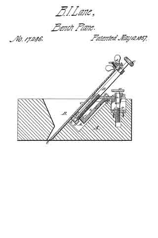
To all whom it may concern:
Be it known that I, J. F. W. ERDMANN, of Philadelphia, county of Philadelphia, in the State of Pennsylvania, have invented a new and useful Improvement in Smoothing-Planes; and I do hereby declare that the following is a full and exact description thereof, reference being had to the accompanying drawings and to the letters of reference marked thereon.
The nature of my invention consists in certain improvements as hereinafter described in smoothing (or scraping) planes for the use of cabinet makers and others.
To enable others skilled in the art to make and use my invention I will proceed to describe its construction and operation, reference being had to the accompanying drawings, where —
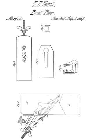
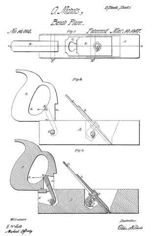
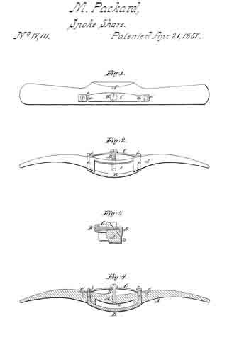
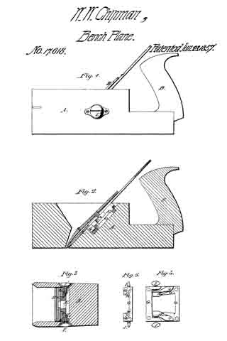
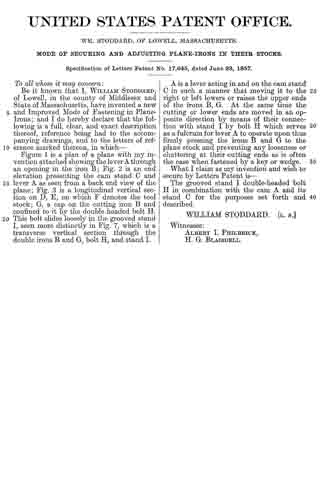
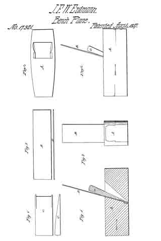
Figure 1 represents a longitudinal section; Fig. 2, a side elevation; Fig. 3, an end elevation; Fig. 4, a top view of plane stock;
Fig. 5, side and edge views of plane iron, and Fig. 6, side and edge views of wedge.
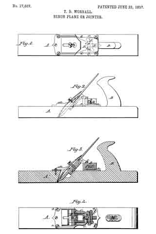
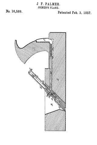
The stock (A) is constructed as that of the ordinary smoothing plane with the exception of the mortise for the bit (B) being made with a reversed inclination to that usually given.
The plane rim or bit (B) is constructed as shown with two working ends or four cutting edges which may be used alternately until all require sharpening.
(C) is the wedge which is constructed so that it may be applied either before or behind the bit (B) which is perfectly plain on its sides.
(D) is an elastic strip inserted in the back of the stock at the throat and against which the bit (B) is pressed when secured by the wedge (O).
It will be observed that by the arrangement of the four edged scraping bit (B) in the ordinary smoothing plane stock, an efficient and economical tool is made, which may be constructed to adapt itself to every variety of work, while by constructing the same as described the cutting angle of the bit may be varied by simply shifting the wedge (C) from one to the other side of the said bit, always pressing the said bit firmly against the elastic strip (D), which latter effectually prevents any shaving from entering the throat of the plane back of the iron, and also makes the plane work more easily, and satisfactorily from the fact of making the iron very slightly elastic.
I am aware that an iron similar to mine is known as a scraper and that irons have been adjusted in stock, with mechanisms for changing the cutting (or scraping) angle and do not wish therefore to be understood as claiming such features as my invention, but
Having described the construction of my improved plane what I claim as my invention and desire to secure by Letters Patent is:-
Placing in the throat of the plane back of the iron, the elastic strip (D) substantially as and for the purposes described.
In testimony whereof I have hereunto set my hand this 28th day of May, 1857.
JOHN FR. W. ERDMANN.
Witnesses:
D. MAJOR GODWIN,
WM. T. GODWIN.