No. 111,890 – Improvement In Joiners’ Planes (George Allen Warren) (1871)

[paiddownloads id=”178″]111890


UNITED STATES PATENT OFFICE.

_________________

GEORGE ALLEN WARREN, OF NORTH BRIDGEIVATER, MASSACHUSETTS.

IMPROVEMENT IN JOINERS’ PLANES.

_________________

Specification forming part of Letters Patent No. 111,890, dated February 14, 1871.

_________________

To all whom it may concern:

Be it known that I, GEORGE ALLEN WARREN, of North Bridgewater, of the county of Plymouth, of the State of Massachusetts, have invented a new and useful Improvement in Joiners’ Planes; and I do hereby declare the same to be fully described in the following specification and represented in the accompanying drawings, which show the invention applied to a plane, termed the “Bailey Plane,” it embracing one or more improvements patented by Leonard Bailey.

My invention, or lateral adjuster, as hereinafter described, is to enable a person to effect a lateral movement of a plane iron or bit in either direction, so as to adjust its cutting-edge in parallelism with the bearing-surface ofthe plane-stock.

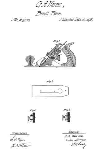
Of the said drawings, Figure 1 denotes a longitudinal section of a plane with my invention applied to it. Fig. 2 is an under side view of the plane-iron or cutter, showing its longitudinal slot, which receives the eccentric of the lateral adjuster. Fig. 3 is a side elevation, and Fig. 4 a top view, of the eccentric and its operative milled head.

In such drawings, A denotes the plane-stock, and B the cutter or plane-iron, they being represented as provided with mechanism for adjusting the cutter longitudinally, and for clamping it down to its bed or bearing-sun face a.

The lateral adjuster is shown at b as consisting of a disk fixed eccentrically on a vertical journal, c, which goes through the bed at or near its upper part, and into the shank d of a milled head, e, the said journal and shank being held in connection by a clamp-screw, f. The eccentric enters the longitudinal slot g of the plane-iron, and has a diameter equal to the width of the slot. On revolving the eccentric more or less the plane-iron may be moved or tilted laterally either way, so as to bring its cutting-edge into proper adjustment with the bearing or lower surface of the plane-stock.

The devices for effecting the longitudinal adjustment of the plane-iron consist of a bent lever, C, and a screw, D, arranged and applied to the said iron and the stock in manner as represented, the devices for clamping the iron to the stock being the headed screw E, the slotted lever F, and the eccentric or cammed lever G, operating against a spring, H, all being as shown, and as commonly made and used in the Bailey plane.

I make no claim to anything, arrangement, or combination of devices as set forth and described in the United States Patent, No.67,398, to Bailey, or in the United States Patent, No. 64,790, to Palmer. My mechanism for effecting lateral adjustment of the bit or plane-iron and the application of such mechanism to the bit, or the arrangement of the adjusting mechanism with the slot of the bit and with the stock of the plane differs materially from anything represented or described in either of such patents, and is particularly advantageous or effective and simple in construction and application.

I claim —

1. The lateral adjuster, as described, as composed of the disk b, the journal c, the socketed shank d, with its clamp-screw and head, as set forth.

2. The arrangement of the said lateral adjuster, as described, with the bed of the stock, and with slot e of the plane-iron, all being substantially as and to operate as explained.

GEORGE ALLEN WARREN.

Witnesses:
R. H. EDDY,
J. R. SNOW.

No. 14,635 – Spoke Shave (Martin Snow) (1856)

[paiddownloads id=”32″]14635


UNITED STATES PATENT OFFICE.

_________________

MARTIN SNOW, OF NORTH BRIDGEWATER, MASSACHUSETTS.

SPOKE-SHAVE.

_________________

Specification of Letters Patent No. 14,635, dated April 8, 1856.

_________________

To all whom it may concern:

Be it known that I, MARTIN SNOW, of North Bridgewater, in the county of Plymouth and State of Massachusetts, have invented an Improved Manufacture of a Knife or Cutter for a Spoke or Heel Shave; and I do hereby declare that the same is fully described and represented in the following specification and the accompanying drawings, of which —

Figure 1, is a rear edge view or elevation;
Fig. 2, an underside view, and Fig. 3, a transverse section of one of the said articles.
Fig. 4 shows an underside view, and Fig. 5, an edge view of a shave, having said cutter or knife applied to it.

Such knife is constructed of steel and with each of its starts A, A, extending from the blade B, parallel to one another, and with each bent or split in two parts, as seen at a, and b, and so that the outer part or portion b, shall serve as a spring to hold the starts or knife firmly in place within the sockets or receiving holes of the stock, D, when the knife is applied to said stock.

Spoke or heel shave knives as usually affixed to stocks are either confined thereto by separate wedges or screw clamps. The contrivances which I employ to hold the knife in place form one and the same piece with it, as well as parts of its starts.

I am aware that it is not new to hold an article in place by means of a spring, therefore I do not claim such, my invention relating to a new or improved manufacture, which of itself is a new article in the market, and from its peculiar construction is rendered one, which is not only very simple, but one of great utility.

The practical use of such a spoke shave or heel knife for upward of a year has proved that when its starts are so made, there is not the slightest difficulty in maintaining the knife in place by them; the depth of its cut being adjusted by simply driving the starts backward within their socket holes as circumstances may require.

What I claim is –

My new or improved manufacture of a heel or spoke shave knife made of one piece of steel and with both of its starts bent or formed in the shape of springs, in manner as specified.

MARTIN SNOW.

Witnesses:
SHEPARD W. SNOW,
EDWARD SMITH.

No. 17,111 – Adjusting And Holding The Knives Of Spokeshaves (Manley Packard) (1857)

[paiddownloads id=”39″]17111


UNITED STATES PATENT OFFICE.

_________________

MANLEY PACKARD, OF NORTH BRIDGEWATER, MASSACHUSETTS.

METHOD OF ADJUSTING AND HOLDING THE KNIVES OF SPOKESHAVES.

_________________

Specification of Letters Patent No. 17,111, dated April 21, 1857.

_________________

To all whom it may concern:

Be it known that I, MANLEY PACKARD, of North Bridgewater, in the county of Plymouth and State of Massachusetts, have invented a new and useful Iniproveinent in Spoke or Heel Shaves; and I do hereby declare that the same is fully described and represented in the following specification and the accompanying drawings, of which —

Figure 1, is a top view, Fig. 2, a rear elevation, Fig. 3, a transverse and central section, and Fig. 4, a longitudinal section of one of my improved articles.

In these drawings A, denotes the handle or stock of the shave; B, the curved cutter knife made in the usual manner with starts a, a, which when the knife is in place in the stock, extends in the usual manner, through holes or mortises made in the same. The cutting edge of the knife operates in connection with a metallic bearer rest b, arranged in front of it, the same constituting the front boundary of the throat c, through which the shavings escape when the tool is in use. So far as the above mentioned parts are concerned, the instrument does not differ from many other spoke shaves.

My improvement which has relation to a means of confining the starts in the stock consists not only in employing a bow spring C, to extend from one start to the other and rest on the upper side of the stock as shown in the drawings, but in having a screw D, to extend through the middle part of the said spring and screw into the stock, the head of the screw being in contact with the top surface of the spring. By screwing the screw into the wood, the bow spring will have its ends forced against the starts so as to hold them firmly in place, an abutment of metal, c’, being placed against each start and fastened in the stock, as shown in Figs. 1, and 4.

By the above described arrangenient and application of the bow spring and screw with reference to the stock and starts of the knife, the fixation of the knife in the stock, and at any distance from the bar b, is a matter which can be accomplished with ease and certainty, the knife not being liable to change its position after once having been adjusted. Besides this, the arrangement of the fastening contrivances, causes them to be so isolated from the sides of the stock as not to interfere with the operations of a workman, who may be using the instrument. The inner corner of each start is beveled or charnfered olf a little as shown at f, in order that when the starts are being driven or pressed through the stock, they may go clear of the ends of the spring so as not to injure it.

My improveinent is one of much utility, as while it affords a simple and efficient means of maintaining the knife in place in the stock it is not in the way of a workman as clamp screws are when extended into and from the sides of the stock.

I do not claim applying either a wedge or a clamp screw to each start in order to keep it in place in the stock, but

What I do claim is —

The above described new arrangement of the clamp screw and bow spring with respect to the handle and starts of the knife or cutter and so as to operate therewith substantially as specified.
In testimony whereof I have hereunto set my signature.

MANLEY PACKARD.

Witnesses :
MARSHALL M. PACKARD,
J. R. PERKINS.