No. 1,221,436 – Plane (John W. Gaede) (1917)

[paiddownloads id=”717″]1221436


UNITED STATES PATENT OFFICE.

_________________

JOHN W. GAEDE, OF CLEVELAND, OHIO.

PLANE.

_________________

1,221,436. Specification of Letters Patent. Patented Apr. 3, 1917.
Application filed April 7, 1915. Serial No. 19,824.

_________________

To all whom it may concern:

Be it known that T, JOHN W. GAEDE, a citizen of the United States, residing at Cleveland, in the county of Cuyahoga and State of Ohio, have invented certain new and useful Improvements in Planes, of which the following is a specification.

This invention relates generally to planes, and particularly to that class of such devices comprising a main body portion having the usual face provided with a throat, together with a bit and cap structure comprising a bit, a cap and clamping means carried by the cap and engaging in a suitable recess in the bit and arranged in a manner such that it may clamp the parts in place on the body portion on the one hand, and it may be released to free the cap and plate from the body portion but still maintain engagement between the two until these parts are removed entirely from the plane, the arrangement of these parts being such that when they are replaced in the plane the previous adjustment of the bit with respect to the cap and the body of the plane is not disturbed.

The invention may be further briefly summarized as consisting in the construction and combination of parts hereinafter set forth in the following description, drawings and claims.

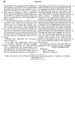
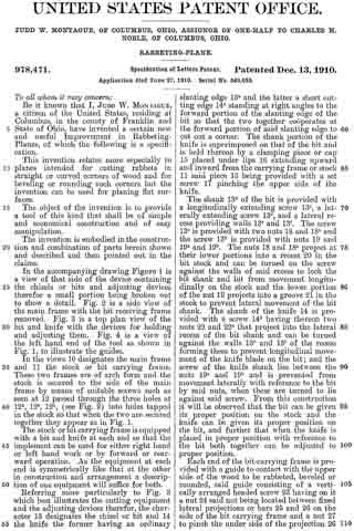
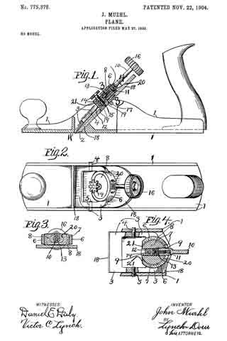
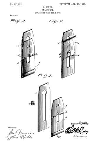
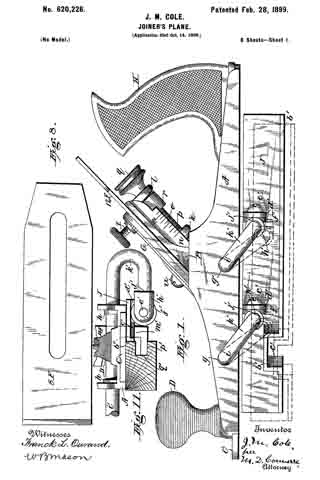
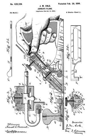
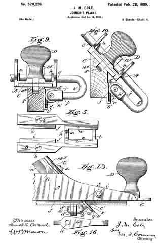
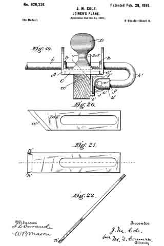
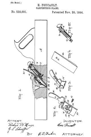
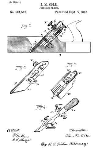
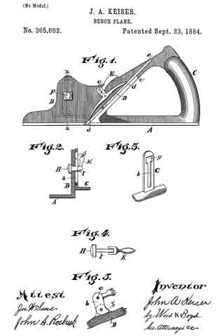
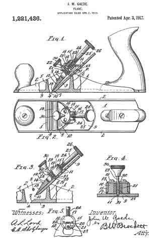
Referring to the drawings, Figure 1 is a side elevation of the plane broken away to show the bit and the adjacent parts in section; Fig. 2 is a top plan view; Fig. 3 is an enlarged sectional view showing the bit and cap partially removed; Fig. 4 is a cross sectional view showing the arrangement for holding the clamping screw in place; and Fig. 5 is a detail sectional view of the arc-shaped guides and cylindrical slide.

In carrying out the invention any preferred form and construction of parts may be employed so long as they possess the necessary characteristics, but I have shown one arrangement in the drawings, and in such embodiment the plane body comprises a base 1 having upwardly extending side flanges 2. The base 1 is provided with a smooth under-surface 3, and this surface is interrupted at the usual point by the throat opening 4. Just forward of this opening is an upwardly extending web 5 extending from one side flange 2 to the other and to the rear of this opening is another upwardly extending web 6 for a purpose to be described. The rear face 7 at the rear of the throat opening 4 is beveled as is usual in devices of this character. Extending from one side flange 2 to the other is a pin or rod 8 and it is between this rod and the upper edge of the web 6 that the bit and cap are located and clamped.

The bit 9 is provided with a cutting edge 10 and a longitudinally extending row of perforations 11 in its upper face. Above this bit 9 is the cap 12 provided with a tapered end portion 13 engaging on the top of the bit and having a transverse recess 14 for receiving the pin or rod 8. The cap is also provided at the back end with an upwardly extending cylindrical portion 15 which is out away at the rear, as shown in Fig. 2, and for a purpose which will be described. This cylindrical portion is also cut away at the front, thus forming two arc-shaped guides, and these guides receive a cylindrical block 16 which has a lower flange 17 for holding the block from moving upward through the arc-shaped guides. The block is held in place by an upper plate 18 secured thereto by screws 19. The cylindrical block 16 is slotted at 20 in a radial direction to receive a sliding block 21 which is provided with a threaded shank 22 engaging in a threaded opening 23 in the end of a screw shank 24 threaded into an opening in the cylindrical block 16, as is clearly shown in Fig. 1. This threaded shank 24 forms a part of an adjusting screw 25 provided with a knurled finger piece 26. The sliding block 21 is provided with an opening 27 for the reception of a shank 28 of a clamping screw 29 which is provided with a finger piece 30 at one end, and a tip 31 for engagement in the opening 11. The clamping screw 29 passes through a slot 32 in the plate 18, and this slot is less in width than the diameter of the threaded shank 28 so that when the plate 18 is in place the clamping screw may not be removed from the sliding block 21. It will be seen from the foregoing that when the clamping screw is forced downward with its tip in one of the recesses 11, the cap plate will be forced against the pin 8 and the bit will be forced against the upper edge of the web 6, with the result that the parts will be held firmly in place, it being possible, however, to adjust the bit by operating the adjusting screw 25 and to shift the plate laterally by swinging the adjusting screw from one side to the other, the block 16 turning in arc-shaped guides formed by the cylindrical portion 15.

It will also be noticed that when the bit and cap are to be removed, the clamping screw is released, and the cap and bit may be removed bodily and may be returned to position without the adjustment of the parts being affected.

Having described my invention, I claim:–

1. A plane having a bit support, an abutment opposite said support and forming therewith a seat, bit and cap members cooperating as a unit and lying in said seat, and bit and cap securing and interengaging devices carried by said unit for securing the unit in its seat and arranged to unpreventably maintain the assembled relation of the bit and cap while in their seat and until complete removal of the unit from said seat.

2. In a plane, a main body portion having a throat and a support for holding the bit member in its working plane, an abutment opposite said support and spaced therefrom, a bit member and a cap member lying in the space between the abutment and support, and means carried by said members for expanding them between the abutment and support in a direction normal to the plane of the bit and thereby securing them in place, said means being arranged to produce and unpreventably maintain interengaging relation between said members until removed together from said body portion.

3. A plane, comprising a body having a throated base, a bit support, and a rod opposite said support, a bit resting on said support and entering said throat and provided with a recess, a cap lying on said bit and having a seat to receive said rod, and a clamping screw carried by said cap and entering said recess, said screw when turned in one direction clamping the bit and cap in place, and means for preventing withdrawal of said screw from said recess while the bit and cap are in place in the body, whereby the bit and cap must be removed and inserted as a unit.

In testimony whereof I affix my signature in presence of two witnesses.

JOHN W. GAEDE.

Witnesses:
ALTON H. BEMIS,
A. L. LORD.

_________________

Copies of this patent may be obtained for five cents each, by addressing the “Commissioner of Patents, Washington, D. C.”
_________________

No. 1,092,326 – Fastening For Plane-Bits (John Bahmiller) (1914)

[paiddownloads id=”695″]1092326


UNITED STATES PATENT OFFICE.

_________________

JOHN BAHMILLER, OF SALEM, OHIO.

FASTENING FOR PLANE-BITS.

_________________

1,092,326. Specification of Letters Patent. Patented Apr. 7, 1914.
Application filed November 25, 1912. Serial No. 733,449.

_________________

To all whom it may concern:

Be it known that I, JOHN BAHMILLER, a citizen of the United States, residing at Salem, in the county of Columbiana and State of Ohio, have invented certain new and useful Improvements in Fastenings for Plane-Bits, of which the following is a specification, reference being had to the accompanying drawings.

This invention relates to new and useful improvements in fastenings for plane-bits and has for its object to provide a fastening which will admit of the bit being readily adjusted to the various positions desired.

A further object of the invention resides in providing a bit having a central longitudinal slot, the one wall of which is provided with rack teeth and a still further object resides in providing means on the securing member between the bit and cap-iron adapted for cooperation with said rack teeth to adjust said bit to its various positions.

A further object of the invention resides in providing a device which is extremely simple and durable in construction, inexpensive to manufacture and one which will be very eflicient and useful in operation.

With these and other objects in view, the invention consists in the novel features of construction, combination and arrangement of parts as will be hereinafter referred to and more particularly pointed out in the specification and claim.

In the accompanying drawing forming a part of this application, Figure 1 is a plan view of a bit showing my improvements applied to use thereon. Fig. 2 is a vertical longitudinal section therethrough; and Fig. 3 is a perspective view of the sleeve member adapted to cooperate with the rack teeth on the bit.

In describing my invention, I shall refer to the drawing in which similar reference characters designate corresponding parts throughout the several views and in which —

1 indicates a bit such as is used in the usual bench plane or the like, the same being provided with a central longitudinal slot 2, the forward end of which is enlarged as shown at 3. The under face of the bit 1, at the outer end thereof, has counter-sunk therein and welded or otherwise similarly secured thereto, the hard metal surface 4, which extends to the cutting edge thereof and one wall of the slot 2 is provided with rack teeth for the greater portion of its length, as shown at 5. A cap-iron 6 of the usual construction, is also provided, the same having an opening 7 therein, and any other such openings as are demanded by the construction of the plane to which the same is to he applied. This opening 7 is threaded and adapted to receive in engagement therewith, the threaded end of a screw 8 which is extended through the slot 2 of the bit 1. In order to adjustably secure the bit and cap-iron together, however, and properly support the screw 8, I provide a substantial sleeve member 9, which is greater in diameter than the width of the slot 2 and is externally reduced at one end thereof to permit a portion thereof to extend through said slot. This reduced portion is of substantially the same diameter as the width of said slot and is provided with rack teeth, as shown at 10, to engage the teeth 5 in the one wall of said slot. This reduced portion with its rack teeth 10 thereon forms a substantial gear and the outer periphery of the enlarged upper portion of said member 9 is knurled to be readily grasped by the operator and turned. The inner periphery of this sleeve member from the enlarged end thereof, is increased in width as shown at 11 to provide an annular shoulder and as the screw 8 is adapted to extend through this sleeve member, the head of said screw may be readily seated on this annular shoulder.

In setting up the device, the sleeve member 9, with the screw 8 extended therethrough, is first disposed in the enlarged portion 3 of the slot 2 and the cap-iron 6 brought into position to be engaged with the threaded end of said screw. The sleeve is then moved into the slot 2 until the teeth 10 are engaged with the teeth 5 of said slot, whereupon said member 9 is rotated until the bit is properly adjusted with respect to the cap-iron. When the proper adjustment has been made, the screw 8 is then turned until the same securely clamps said member 9 in its adjusted position and the bit is then ready for use. Should, during the operation of the plane, it be desired to adjust said bit, it is only necessary to turn the screw 8 in the opposite direction to loosen the same, whereupon the member 9 may be rotated, which operation will adjust said bit on the cap-iron. The screw is then tightened to securely retain the bit in the desired position.

From the foregoing it will be seen that I have provided a simple, inexpensive and efficient means for carrying out the objects of the invention, and while I have particularly described the elements best adapted to perform the functions set forth, it is obvious that various changes in form, proportion and in the minor details of construction may be resorted to without departing from the spirit or sacrificing any of the principles of the invention.

The hard metal surface 4 which is counter-sunk in the under face of the bit 1, and extends to the cutting edge thereof, is a plate which will prevent the cutting edge from being unnecessarily nicked during the use of the device and thereby obviate the necessity of constantly sharpening the same, The provision of such a plate on the bit will not materially add to the cost thereof and in the end will save considerable time and expense.

Having thus described this invention, what I claim is:–

In a plane, the combination with a cap iron having a threaded opening arranged about centrally therein; of a bit provided with a longitudinal slot terminating in an enlargement at one end thereof, one wall of said slot being provided with teeth extending for the greater portion of its length, a sleeve disposed in the slot of said bit having teeth formed on the outer periphery thereof, in engagement with the teeth of the one vvall of said slot, the teeth on said sleeve also contacting lightly with the opposite wall of said slot to prevent a loose movement of the sleeve therein, a disk-like head member formed on the upper end of said sleeve to project on opposite sides of the slot in said bit and rest on the top face of the latter, said head member being of less diameter than the diameter of the enlargement of said slot and provided with a socket in the top face thereof, means provided on the outer peripheral edge of the head member, whereby to readily grasp the same, and a headed screw disposed through said sleeve and engaged at its lower end with the threaded opening of said cap iron, the head of said screw being received snugly in the socket of the head of said sleeve to bind tightly therein and retain the bit in any adjusted position with respect to the cap iron.

In testimony whereof I hereunto affix my signature in the presence of two witnesses.

JOHN BAHMILLER.

Witnesses:
K. L. COBOURN,
MYRTA L. COBOURN.

_________________

Copies of this patent may be obtained for five cents each, by addressing the “Commissioner of Patents, Washington, D. C.”
_________________

No. 978,471 – Rabbeting-Plane (Judd W. Montague) (1910)

[paiddownloads id=”675″]978471


UNITED STATES PATENT OFFICE.

_________________

JUDD W. MONTAGUE, OF COLUMBUS, OHIO, ASSIGNOR OF
ONE-HALF TO CHARLES H. NOBLE, OF COLUMBUS, OHIO.

RABBETING-PLANE.

_________________

978,471. Specification of Letters Patent. Patented Dec. 13, 1910.
Application filed June 7, 1910. Serial No. 569,035.

_________________

To all whom it may concern:

Be it known that I, JUDD W. MONTAGUE, a citizen of the United States, residing at Columbus, in the county of Franklin and State of Ohio, have invented a certain new and useful Improvement in Rabbeting-Planes, of which the following is a specification.

This invention relates more especially to planes intended for cutting rabbets in straight or curved corners of wood and for beveling or rounding such corners but the invention can be used for planing flat surfaces.

The object of the invention is to provide a tool of this kind that shall be of simple and economical construction and of easy manipulation.

The invention is embodied in the construction and combination of parts herein shown and described and then pointed out in the claims.

In the accompanying drawing Figure 1 is a view of that side of the device containing the chisels or bits and adjusting devices therefor a small portion being broken out to show a detail. Fig. 2 is a side view of the mainframe with the bit receiving frame removed. Fig. 3 is a top plan view of the bit and knife with the devices for holding and adjusting them. Fig. 4 is a view of the left hand end of the tool as shown in Fig. 1, to illustrate the guides.

In the views 10 designates the main frame and 11 the stock or bit carrying frame. These two frames are of arch form and the stock is secured to the side of the main frame by means of suitable screws such as seen at 12 passed through the three holes at 12a, 12a 12a (see Fig. 2) into holes tapped in the stock so that when the two are secured together they appear as in Fig. 1.

The stock or bit carrying frame is equipped with a bit and knife at each end so that the implement can be used for either right hand or left hand work or by forward or rearward operation. As the equipment at each end is symmetrically like that at the other in construction and arrangement a description of one equipment will suffice for both.

Referring more particularly to Fig. 3 which best illustrates the cutting equipment and the adjusting devices therefor, the character 13 designates the chisel or bit and 14 the knife the former having an ordinary slanting edge 13a and the latter a short cutting edge 14a standing at right angles to the forward portion of the slanting edge of the bit so that the two together cooperates at the forward portion of said slanting edge to cut out a corner. The shank portion of the knife is superimposed on that of the bit and is held thereon by a clamping piece or cap 15 placed under lips 16 extending upward and inward from the carrying frame or stock 11 said piece 15 being provided with a set screw 17 pinching the upper side of the knife.

The shank 13b of the bit is provided with a longitudinally extending screw 13c, a laterally extending screw 13d, and a lateral recess providing walls 13e and 13f. The screw 13e is provided with two nuts 18 and 18a and the screw 13d is provided with nuts 19 and 19a and 19b, The nuts 18 and 18a project at their lower portions into a recess 20 in the bit stock and can be turned on the screw against the walls of said recess to lock the bit shank and bit from movement longitudinally on the stock and the lower portion of the nut 19 projects into a groove 21 in the stock to prevent lateral movement of the bit shank. The shank of the knife 14 is provided with a screw 14b having thereon two nuts 22 and 22a that project into the lateral recess of the bit shank and can be turned against the walls 13e and 13f of the recess forming them to prevent longitudinal movement of the knife blade on the bit; and the screw of the knife shank lies between the nuts 19a and 19b and is prevented from movement laterally with reference to the bit by said nuts, when these are turned to lie against said screw. From this construction it will be observed that the bit can be given its proper position on the stock and the knife can be given its proper position on the bit, and further that when the knife is placed in proper position with reference to the bit both together can be adjusted to proper position.

Each end of the bit-carrying frame is provided with a guide to contact with the upper side of the wood to be rabbeted, beveled or rounded, said guide consisting of a vertically arranged headed screw 23 having on it a nut 24 said nut being located between fixed lateral projections or bars 25 and 26 on the side of the bit carrying frame and a nut 27 to pinch the under side of the projection 26 after the screw or guide has been properly adjusted. Each end of the main frame is provided with a guide to contact with the vertical or upright side of the wood to be rabbeted, beveled or rounded, said guide consisting of a horizontally arranged headed screw 28 having on it a nut 29, said nut being located between fixed projections or ears 30 and 31 on the main frame and a nut 32 to pinch the outer ear 31 after the screw or guide has been properly adjusted. The ears or projections 30 and 31 are formed on a block 33 detachable from the foot of the frame, said block being provided with a pin 33a to enter a socket in said foot and a set screw 34 screwed into a suitable hole in the foot. This block 33 and its contained guide can be removed and the plane used for planing fiat or other surfaces.

The arched form of the main frame and the bit carrying frame when combined permit the gripping of the device with the hand at either end according to the direction in which it is desired to push the device. The planing operation can be performed by either pushing or drawing the device and with the tool grasped either in left hand or right hand manner. In other words the manipulation of the plane can be accommodated to the grain of the wood and so as to avoid as far as practical planing against grain. The knife insures a smooth clean surface at the upright or vertical side of the rabbet. With this construction, and particularly because the cutting corner is free from obstructing parts in front of it two rabbets can be made with great facility in circular, oval or other curved pieces such for example as picture frames and other like structures.

What I claim is:

1. In a plane, the combination with a stock, of a bit with means in connection therewith for longitudinally and laterally adjusting the same with reference to the stock, a knife to angularly cooperate with the cutting edge of said bit, and means connected with the bit and knife for operating the knife to adjust the same with reference to the bit, the knife being movable by moving the bit.

2. In a plane, the combination with a guiding and holding stock, of a removable bit and a removable angularly cooperating knife on the bit, means on the bit for operating the knife to adjust the same with reference to the bit, and means for fixing both the bit and knife to the stock with their cutting edges wholly forward of the material of the stock.

3. In a plane, the combination with a stock, a bit and a knife, means for securing the knife to stand at one end of the edge of the bit and at an angle to the edge of the bit to form a cutting corner, combined with an arched handling frame 10 and means for securing the stock thereto at the side of the latter opposite that containing said cutting corner.

4. In a plane the combination with the stock having a recess 20 and a groove 21 of a bit provided with a longitudinally extending screw 13c and a laterally extending screw 13d and a lateral recess providing walls 13e and 13f, nuts 18 and 18a on the screw 13c extending into said recess 20 and nuts 19 and 19a and 19b on said screw 13d, the nut 19 projecting into said groove 21, a knife having its cutting edge standing at an angle to the cutting edge of the bit and cooperating therewith, said knife provided with a longitudinally extending screw 1 having nuts 22 and 22a thereon projecting between the walls 13e and 13f and said screw lying between the nuts 19a and 19 whereby the bit can be adjusted independently of the knife and the knife independently of the bit, substantially as described.

5. In a plane the combination with the stock having a recess 20 and a groove 21, of a bit provided with a longitudinally extending screw 13c and a laterally extending screw 13d and a lateral recess providing walls 13e and 13f, means on the screw 13c extending into said recess 20 to adjust and fix the same with reference to the stock, and nuts 19 and 19a and 19b on said screw 13d, the nut 19 projecting into said groove 21, a knife on the bit having its cutting edge standing at an angle to the cutting edge of the bit and cooperating therewith, said knife provided with a longitudinally extending screw 14b having means thereon to engage the aforesaid walls 13e and 13f to longitudinally adjust and fix the same and said screw lying between the nuts 19 and 19a, whereby the knife can be adjusted independently of the bit and the bit independently of the knife, substantially as described.

JUDD W. MONTAGUE.

Witnesses:
CHAS. H. NOBLE,
BENJ. FINCKEL.

No. 778,849 – Wood-Scraper (James R. Ellis) (1905)

[paiddownloads id=”611″]778849


UNITED STATES PATENT OFFICE.

_________________

JAMES R. ELLIS, OF CLEVELAND, OHIO.

WOOD-SCRAPER.

_________________

SPECIFICATION forming part of Letters Patent No. 778,849, dated January 3, 1905.
Application filed July 27, 1904. Serial No. 218,415.

_________________

To all whom it may concern:

Be it known that I, JAMES R. ELLIS, a citizen of the United States, residing at Cleveland, in the county of Cuyahoga and State of Ohio, have invented new and useful Improvements in Wood-Scrapers, of which the following is a specification.

This invention is an improved wood-scraper for the use of carpenters and cabinet-makers, and is characterized particularly by improvement with respect to the manner in which and the means by which the scraping-blade is held in the stock and also by other improved details of construction, as will be more fully apparent from the following description.

In the accompanying drawings, Figure 1 is a front elevation of the tool. Fig. 2 is a rear elevation. Fig. 3 is a side elevation. Fig. 4 is a section on the line 4 4 of Figs. 1 and 2. Fig. 5 is a bottom plan view.

Referring specifically to the drawings, 6 indicates the back plate of the stock. This has a backwardly-extending foot 7, forming part of the face-plate of the tool. Said back plate also has at the top of its side edges backwardly-projecting ears 8 for attachment of the handles, which are indicated at 9. These handles are detachably secured to the tool by means of a rod 10, which is fast to one handle and fits snugly through holes in the ears and into the other handle, where its end is screwed into the nut 11. To remove the handles, it is simply necessary to unscrew the same and pull the rod out of the ears. This is useful in packing and carrying the tool. The front of the stock has two spaced upright portions 12, located at each side of the throat, which receives the blade 13. The uprights 12 are cast integrally with a forwardly-extending foot 14, which, with the foot 7, forms the face-plate of the tool, which slides over the work. This face is preferably slightly convex, so that the knife will take better into the work.

The blade 13 is gripped at its side edges between the back plate 6 and the uprights 12, and the foot 14 is cut away in front of the cutting edges of the blade, as at 15. The front and back pieces are held together and the side edges of the blade clamped therebetween by means of screws 16, which extend through the back plate into the upright parts 12 of the front.

To hold the knife at adjustment, a screw 17 extends through the back plate at the middle thereof, with its point bearing against the blade near the cutting edge. This screw serves to hold the blade at adjustment, and it also serves to slightly spring the knife forward at the middle, and this action is permitted by the recess 15 in front of the knife. This action is advantageous, and it is to permit the same that the screw 17 and the recess 15 are provided. The slight warp or curve in the knife produced by the pressure of the screw 17 produces a slight curve of its cutting edge, so that said edge takes the wood at a slight angle on each side with respect to the middle, whereby an easy cut is produced and chattering and stuttering is avoided. Furthermore, the cut can be adjusted within certain limits without loosening the blade, since the more the blade is bent forward by the screw 17 the deeper the cut will be. Variation in the angle of the blade is not possible, since its side edges are firmly clamped. The top end of the blade projects above the stock, so that the tool can be turned over and the top end used, if desired, as in rough work. In close quarters the handles can be removed and the scraper used without the handles.

What I claim as new, and desire to secure by Letters Patent, is —

1. The combination with a stock and face-plate, of a blade clamped at its side edges in the stock and extending through a throat in the face-plate, the latter being recessed in front of the blade, and an adjusting-screw bearing laterally against the back face of the blade, opposite the recess, and arranged to warp or curve the blade.

2. The combination with front and back plates, the back plate having ears at the side edges thereof, and a blade clamped between the plates, of removable handles extending laterally from said edges, and a screw-rod extending through the ears and connecting the handles.

3. The combination of front and back plates having respectively forwardly and rearwardly extending feet forming a face-plate, a blade clamped at its side edges, only, between the plates, the front plate being recessed in front of the blade, and an adjusting-screw extending through the back plate and bearing against the blade, and arranged to warp or curve the blade.

In testimony whereof I have signed my name to this specification in the presence of two subscribing witnesses.

JAMES R. ELLIS.

Witnesses:
SHIRLEY BOMMHARDT,
JOHN A. BOMMHARDT.

No. 775,378 – Plane (John Muehl) (1904)

[paiddownloads id=”610″]775378


UNITED STATES PATENT OFFICE.

_________________

JOHN MUEHL, OF CLEVELAND, OHIO.

PLANE.

_________________

SPECIFICATION forming part of Letters Patent No. 775,378, dated November 22, 1904.
Application filed May 27, 1903. Serial No. 158,939. (No model.)

_________________

To all whom it may concern:

Be it known that I, JOHN MUEHL, a citizen of the United States of America, residing at Cleveland, in the county of Cuyahoga and State of Ohio, have invented certain new and useful Improvements in Planes; and I hereby declare the following to be a full, clear, and exact description of the invention, such as will enable others skilled in the art to which it pertains to make and use the same.

This invention relates to a new and useful improvement in bench-planes.

The object of this invention is to provide a device of this character which can be used on any kind of wood and will not clog or tear the wood.

A further object of my invention is to reduce the cost of manufacture and simplify the construction of bench-planes by providing a simple arrangement of bit-adjusting mechanism by means of which the bit can be easily and accurately adjusted longitudinally to regulate the depth of the cut and laterally to line up the edge of the bit with the sole or face of the plane.

My invention therefore consists in providing a plane having a plate secured in the stock thereof which serves both as a cap and as a clamping-plate and which also forms the sole support for all the adjusting mechanism.

My invention further consists in providing an arrangement of bit-adjusting mechanism by means of which the bit can be set by operating a single lever, by the rotation of which the longitudinal adjustment of the bit can be secured, and by the oscillatory movement of which the edge of the bit can be alined with the sole or face of the plane.

My invention further consists in the features of construction and combination of parts hereinafter described in the specification, pointed out in the claims, and illustrated in the drawings.

In the accompanying drawings, Figure 1 is a side elevation, partly in section, of my improved plane. Fig. 2 is a top plan. Fig. 3 is a section on line 3 3, Fig. 1. Fig. at is a section on line 4 4, Fig. 1.

Again referring to the drawings, 1 represents the stock of the plane, which is provided with the bit-opening or throat 2. A combined cap or clamping plate 3 is secured in the cheek-plates of the stock by means of pins 4 and 5. The lower edge of the plate 3 is provided with a knife-edge which is arranged flush with the sole or face of the plane.

Near the top of the plate 3 is formed a boss 6, in which is formed a screw-threaded opening 7. In the side of the boss and communicating with the opening 7 is formed a slot 20, and the opposite side of the boss is cut away, as at 21. In the screw-threaded opening 7 is arranged a screw-threaded plug 8, in which is formed an opening 9, the axis of which is at a right angle to the axis of the opening 7, and said opening is screw-threaded the greater part of its length. An adjusting-arm 10 is screw-threaded at one end and is arranged to screw into the screw-threaded opening 9 in the plug 8. The plug 8 therefore forms the fulcrum for the single adjusting-arm 10. In the end of the arm 10 is formed a screw-threaded bore 11. A small block 12 is provided with a screw-threaded stem 13, arranged to screw into the bore 11 in the end of the adjusting-arm 10. The exterior screw-thread on the lever 10 and the screw-thread in the plug 8 are preferably right-hand screw-threads, and the internal screw-threads in the end of the lever 10 and the screw-thread on the stem 13 are preferably left-hand screw-threads. In the block 12 is mounted a set-screw 14, which is provided with a reduced end portion 15. The arm 10 is preferably provided with a knob 16. A support 17 is rigidly secured between the cheek-plates of the stock, and between this support 17 and the plate 3 is arranged a bit 18. In this bit are formed a series of holes 19, arranged to receive the end of the set-screw 14, so as to secure the bit to the plate 3 and clamp it against the support 17.

The construction and operation of my plane is so simple that it can be readily understood.

When the knob of the arm is turned to the right, the end of the arm will be screwed down into the plug, thereby advancing the block and causing the bit which is secured thereto to project through the throat of the plane. By turning the knob of the arm to the left the arm will be screwed out of the plug, drawing the block into the plug and retracting the bit in the throat of the plane. Again, by swinging the arm to the left or to the right on the plug as a fulcrurn the opposite edges of the bit can be caused to project through or be retracted in the throat of the plane, thereby securing perfect alinement of the edge of the bit with the sole or face of the plane.

I have described and illustrated my preferred construction; but it will be readily seen that the same can be changed without departing from the spirit of my invention. For instance, most of the screw-threads are provided only for the purpose of allowing the members to rotate in their respective mountings, and any method of mounting which will permit a rotary movement of the members can be substituted and all screw-threads omitted except one on the arm 10 and a corresponding screw-thread either in the plug 8 or on the block 12 and any other means substituted which will allow a free rotary movement and supply a connecting or binding means at the same time.

What I claim is —

1. A plane comprising a stock, a stationary plate, an arm fulcrumed on said plate, and arranged to have both an oscillatory and a rotary movment, a bit, means for causing the arm to travel longitudinally when rotated, and means forming an operative connection between said arm and said bit so that the rotary movement of said arm will cause a longitudinal movement of said bit and the oscillatory movement of said arm will cause a lateral shifting of said bit so as to aline the cutting edge of said bit with the face of the plane.

2. A plane comprising a stock, a stationary plate, a fulcrum rotatably mounted on said plate, an arm rotatably mounted in said fulcrum, a bit, means for causing the arm to travel longitudinally when rotated, and means for forming an operative connection between said bit and said arm so that the rotary movement of said arm will cause a longitudinal movement of said bit and the oscillatory movement of said arm will cause a lateral shifting of said bit, for the purpose set forth.

3. A plane comprising a stock, a stationary plate, a fulcrum rotatably mounted on said plate and provided with a screw-threaded opening, an arm arranged to screw into said screw-threaded opening, a block, means for securing said block to the end of said arm so as to allow the arm to rotate without rotating said block, a bit, and means for securing said block to said bit.

4. A plane comprising a stock, a stationary plate, a fulcrum rotatably mounted on said plate and provided with a screw-threaded opening, an arm adapted to screw into said fulcrum, a block, means for securing said block to the end of said arm so as to allow the arm to rotate without rotating said block, a bit, and a set-screw for securing said bit to said block.

5. A plane comprising a stock, a stationary plate, a fulcrum rotatably mounted on said plate, an arm arranged to screw into said fulcrum, a block arranged to screw on the end of said arm, a bit and means for securing said block to said bit.

6. A plane comprising a stock, a stationary plate, a fulcrum rotatably mounted on said plate, an arm arranged to screw into said fulcrum and havinga screw-threaded bore in its lower end, a block, a screw-threaded stem formed on said block and arranged to screw into the end of said arm, a bit and means for securing said bit to said block.

7. A plane comprising a stock, a stationary plate, a fulcrum rotatably mounted on said plate, an arm arranged to screw into said fulcrum, a block secured on the end of said arm so as to allow the arm to rotate without rotating the said block, a support, a bit arranged between said plate and said support and a set-screw mounted in said block and arranged to secure the said block to the said bit and clamp said bit between said plate and said support.

8. A plane comprising a stock, a stationary plate, a fulcrum rotatably mounted on said plate, an arm arranged to screw into said fulcrum and having a screw-threaded bore, a block provided with a screw-threaded stem arranged to screw into the bore in said arm, a support, a bit arranged between said plate and said support and a set-screw mounted in said block and arranged to secure said block to said bit and clamp said bit between said plate and said support.

9. A plane comprising a stock, a stationary plate, an arm having a screw-threaded end rotatably secured on said plate, a block provided with a screw-thread arranged to engage the screw-thread on said arm, a bit, and means for securing said bit to said block.

10. A plane comprising a stock, a stationary plate, a fulcrum rotatably mounted on said plate, an arm rotatably secured in said fulcrum and having a screw-threaded bore formed in the end thereof, a block, a screw-thread formed on said block and arranged to screw into the bore of said arm, a bit and means for securing said block to said bit.

11. A plane comprising a stock, a stationary plate, a fulcrum mounted on said plate, an arm rotatably secured in said fulcrum and provided with a screw-threaded end, a block provided with a screw-thread arranged to engage the screw-thread on said arm, a bit and means for securing said bit to said block.

12. A plane comprising a stock, astationary plate, an arm having a screw-threaded bore formed in the end thereof, means for rotatably securing said arm on said plate, a block, a screw-threaded stem formed on said block and arranged to screw into the bore in said arm, a bit and means for securing said block to said bit.

13. A plane comprising a stock, a stationary plate. a fulcrum rotatably mounted on said plate, an arm, means for securing said arm on said fulcrum to oscillate and also to rotate therein. a bit and means for securing said bit to said arm, the arrangement being such that the rotary movement of said arm will cause a longituclinal movement of said bit, and the oscillatory movement of said arm will cause a lateral shifting of said bit for the purpose set forth.

In testimony whereof I sign the foregoing specification, in the presence of two witnesses, this 9th day of May, 1903, at Cleveland, Ohio.

JOHN MUEHL.

Witnesses:
VICTOR G. LYNCH,
G. M. HAYES.

No. 751,671 – Hand-Tool (John E. McCauley) (1904)

[paiddownloads id=”598″]751671


UNITED STATES PATENT OFFICE.

_________________

JOHN E. McCAULEY, OF SPRINGFIELD, OHIO, ASSIGNOR OF ONE-HALF
TO WILLIAM D. BAYLEY, OF SPRINGFIELD, OHIO.

HAND-TOOL.

_________________

SPECIFICATION forming part of Letters Patent No. 751,671, dated February 9, 1904.
Application filed June 15, 1903. Serial No. 161,488. (No model.)

_________________

To all whom it may concern:

Be it known that I, JOHN E. McCAULEY, a citizen of the United States, residing at Springfield, in the county of Clark and State of Ohio, have invented certain new and useful Improvements in Hand-Tools, of which the following is a specification.

My invention relates to hand-tools, and more particularly to hand-planers for planing out the semicircular groove in core-boxes, but may be used in planing like grooves in any article.

The object of my invention is to provide a hand-planer of such construction that at each operation of the tool the cutter will be turned to take an additional cut in such manner that when the operation is complete a semicircular groove will be formed, and a further object is to provide means to adjust the feed of the cutter.

A further object is to provide a sliding frame that can be adjusted to the size of the article to be planed and to elastically hold said frame in engagement with the article.

With these and other objects in view my invention consists of the constructions and combinations hereinafter described, and set forth in the claims.

In the accompanying drawings, which form a part of this specification, Figure 1 represents a planer embodying my invention. Fig. 2 is a detail of the feed device, and Fig. 3 is a detail of one of the side frames with a tension-cushion thereon.

Like parts are represented by similar letters of reference in the several views.

In the drawings, a represents a slide on one side of the frame adapted to engage the top and one side of the article to be planed, and a’ represents another slide on the other side of the frame adapted to rest on the top of the article to be planed and has secured thereto a spring-cushion, which I have shown in the form of an elongated loop a2, adapted to engage the other side of the article to be planed. Cross-rods a3 and a4 rest in bearings on the slides, and clamping-plates a5, having thumb-screws a6 extending through same into screw-threaded perforations in the slides, are provided, so that the slides can be moved to and from each other and adjusted to the size of the article to be planed and fixed in their adjusted positions by said thumb-screws. This adjustment is made so that the spring-cushion a2 will bear against one side of the article to be planed while the operator holds the planer firmly against the opposite side.

A frame b, having perforations through which the cross-rods a3 and a4 extend, is movable longitudinally on said rods and is held in its adjusted position by a set-screw b’. A shaft b2, longitudinally disposed in the line of travel of the planer, is provided with a head b3, having a slot therein, through which a cutter-bar b4 extends at right angles to said shaft and is secured in place by a set-screw b5. Said cutter-bar has a cutting edge extending from said head to and including the outer end thereof. The shaft b2 is journaled in a hanger b6, the upper portion of which is screw-threaded and extends through an opening in the frame b and is tightened in place by a thumb-nut b7. A shaft b8, journaled in the frame b at an angle to the shaft b2, has a ratchet-wheel b9 fixed thereon, and a pair of worm-gears b10, fixed on said shafts, transmit motion from one to the other.

Through an opening in the frame b a handle c is journaled on the cross-rod a4, and on a forwardly and upwardly extending arm c’ of said handle there is a projection c2, which engages the frame b and limits the forward rocking movement of the handle, while a set-screw c3 is employed to adjustably limit the rearward rocking movement of said handle. A pawl c4, pivoted to the arm c’ of the handle, is adapted to engage the ratchet-wheel b9. The construction is such that when the handle is grasped to push the planer forward the handle will rock forward until the stop c2 engages the frame and the pawl will engage and move the ratchet to an extent permitted by this rocking movement, and the cutter-bar will thereby be turned to take an additional cut when the planer is moved forward. By turning the set-screw c3 the extent of the rocking movement can be varied and the feed of the cutter adjusted.

To operate the planer, the slides are adjusted to the article to be planed, as herein-before described, and the frame b is adjusted on the cross-rods so that the shaft which carries the cutter-bar is in line with the longitudinal center of the groove to be cut, with the cutter-bar in a horizontal position at right angles thereto. Then grasping the handle and pushing the planer forward the initial rocking movement will set the cutter in position so that in the forward movement of the planer it will take a cut and at each succeeding forward movement the cutter will be turned sufficiently to take an additional cut and the continued operation of the planer will form a semicircular groove. In practice it may be found convenient after finishing one-half of the groove to reverse the position of the planer, reset the cutter to horizontal position, and plane out the other half from the top of the article being planed in like manner as the first half, or the operator may first rough out the groove with another tool and then finish with a planer embodying my invention.

Having thus described my invention, I claim —

1. In a hand-planer, a frame having laterally-movable slides adapted to elastically contact with the respective sides of the article to be planed, means to fix said slides in their relation to each other, a cutter journaled in said frame, and means to partially rotate said cutter transversely to the line of travel of said planer at each operation of the planer, substantially as specified.

2. In a hand-planer, a frame having laterally-movable slides adapted to engage the respective sides of the article to be planed, one of which has a projecting portion and the other a spring-cushion, said projection and cushion being adapted to contact with the respective sides of the article to be planed, means to fix said slides in their relation to each other, a cutter journaled in said frame, and means to partially rotate said cutter transversely to the line of travel of said planer at each operation of the planer, substantially as specified.

3. In a hand-planer, a frame having laterally-movable slides adapted to engage the respective sides of the article to be planed, one of which has a projection and the other a spring-cushion, said projection and cushion being adapted to contact with the respective sides of the article to be planed, means to fix the relative position of said slides, a laterally-mow able portion of said frame and means to fix its position, a shaft journaled in said portion longitudinally in the line of travel of the planer, a cutter-bar and a head on said shaft adapted to hold said cutter at right angles to said shaft, another shaft journaled in said portion having a ratchet-wheel thereon and a gear connection with said first-named shaft, an operating-hawdle pivoted to rock on said portion, means to adjust and limit said rocking movement, a pawl pivoted on said handle and adapted to engage said ratchet-wheel, substantially as specified.

In testimony whereof I have hereunto set my hand this 2d day of May, A. D. 1903.

JOHN E. McCAULEY.

Witnesses:
PERCY NORTON,
OLIVER H. MILLER.

No. 737,112 – Plane-Bit (Samuel Jones) (1903)

[paiddownloads id=”587″]737112


UNITED STATES PATENT OFFICE.

_________________

SAMUEL JONES, OF JACKSON, OHIO.

PLANE-BIT.

_________________

SPECIFICATION forming part of Letters Patent No. 737,112, dated August 25, 1903.
Application filed January 9, 1903. Serial No. 138,404. (No model.)

_________________

To all whom it may concern:

Be it known that I, SAMUEL JONES, a citizen of the United States, residing at Jackson, in the county of Jackson and State of Ohio, have invented certain new and useful Improvements in Plane-Bits, of which the following is a specification.

Planes designed for carpenters’ and joiners’ use have the bit for the most part reinforced and strengthened by a cap or stay plate, held thereto by a clamp bolt or screw. When sharpening the bit either by grinding or whetting, it becomes necessary to remove the cap or stay plate, so that the face of the bit may be presented to the grindstone or oil-stone to enable the removal of the wire-edge and the securance of a keen cutting edge. The removal and the proper replacement of the cap-plate are almost always attended with vexation for one reason or another, which it is the purpose of the present invention to overcome. This invention enables the proper sharpening of the bit without necessitating the removal of the cap-plate, which is composed of sections hingedly connected, the lower section being free to be turned back upon the bit out of the way and the upper section being secured to the bit in the usual manner to admit of adjustment of the cap or stay plate as the bit wears away.

The invention consists of a plane-bit having a cap or stay plate hinged thereto, so as to be thrown back out of the way to admit of proper sharpening of the bit.

The invention also consists of a cap or stay plate for plane-bits composed of hinged sections.

The invention further consists of the novel features, which hereinafter will be more fully described, claimed, and illustrated in the accompanying drawings, in which —

Figure 1 is a perspective view of a plane-bit embodying the invention. Fig. 2 is a view similar to Fig. 1, showing the lower section of the cap or stay plate folded back upon the bit. Fig. 3 is a perspective view of the bit and cap-plate detached.

Corresponding and like parts are referred to in the following description and indicated in all the views of the drawings by the same reference characters.

The plane-bit 1 may be of any pattern or make adapted for the stock of a carpenter’s or joiner’s plane and is provided with the cap or stay plate 2, secured thereto by the bolt or clamp screw 3. The cap or stay plate is composed of sections 4 and 5, hinged together in any way to admit of the lower section 4 folding back upon the bit out of the way. The stay portion 4 is hinged to the bit 1 through the part 5 and can be turned instantly to occupy either an operative position or be out of the way. The part 5 can be adjusted to admit of shifting the cap or stay plate to compensate for wear of the bit. After the bit has been removed from the plane-stock (not shown) it may be sharpened in the accus-
tomed way by folding the stay-section 4 upon the bit, as shown in Fig. 2, it not being necessary to remove the cap or to loosen the clamp-screw. After the bit has been sharpened the section 4. is turned into a normal position and the bit replaced in the stock in the usual way. This part 4: constitutes, in effect, the reinforcement for the bit and is clamped thereto by the same means employed for securing the bit to the stock or frame.

Having thus described the invention, what is claimed as new is —

1. A plane-bit having a reinforcement hingedly connected therewith, substantially as described.

2. A cap-plate or stay for a plane-bit composed of hinged sections, substantially as specified.

3. In combination with a plane-bit, a stay, an attaching-section having the stay hinged thereto, and means for adjustably connecting the attaching-section to the said bit, substantially as set forth.

4. In combination with a plane-bit, a cap-plate composed of hinged sections, and means for adjustably connecting the upper section with the bit, substantially as specified.

In testimony whereof I affix my signature in presence of two witnesses.

SAMUEL JONES. [L. S.]

Witnesses:
W. T. MORGAN,
E. E. EUBANKS.

No. 729,020 – Block-Plane (John P. Vance) (1903)

[paiddownloads id=”584″]729020


UNITED STATES PATENT OFFICE.

_________________

JOHN P. VANCE, OF DAYTON, OHIO.

BLOCK-PLANE.

_________________

SPECIFICATION forming part of Letters Patent No. 729,020, dated May 26, 1903.
Application filed February 20, 1903. Serial No. 144,229. (No model.)

_________________

To all whom it may concern:

Be it known that I, JOHN P. VANCE, a citizen ofthe United States, residing at Dayton, in the county of Montgomery and State of Ohio, have invented certain new and useful Improvements in Block-Planes; and I do declare the following to be a full, clear, and exact description of the invention, such as will enable others skilled in the art to which it appertains to make and use the same, reference being had to the accompanying drawings, and to the letters of reference marked thereon, which form a part of this specification.

This invention relates to new and useful improvements in block-planes and possesses the novel features hereinafter described and claimed.

Preceding a detail description of the invention reference is made to the accompanying drawings, of which —

Figure 1 is a top plan view of my improved block-plane. Fig. 2 is a side elevation. Fig. 3 is a longitudinal mid-sectional elevation. Fig. 4 is a cross-sectional elevation.

In the specification similar reference letters indicate corresponding parts.

The metallic base or frame consists of the following structural parts: A is the base, from which rises two sides B B, that are joined by transverse ribs D and G. The former rib lies immediately in front of the opening E, through which the cutting edge of the blade J projects, and the rib G forms a support for said blade in the rear part of the frame and whereby the said blade is supported in a proper inclined plane. This inclined plane is a very essential feature of the invention, and to be more specific in describing it it is stated that the angle thereof is approximately not more than twelve degrees. With the cutting-blade held rigidly in such position by the means hereinafter described the work of the plane is rendered comparatively easy and effective.

C designates an integral projection rising from the front portion of the base A and upon which the index-finger of the operator rests.

F is a projection formed integral with the base and projecting beyond the rear end of the base. The object of this projection is to provide a suitable surface to be struck by a hammer or other implement in detaching the blade.

The sides B of the frame are provided on their outer surfaces with suitable grooves A”, which enable a suitable grip of the fingers in operating the plane.

That portion of the base A immediately in the rear of the blade-opening A is provided with a tapering surface A’ of a proper inclination to enable the blade to lie thereon at the angle hereinbefore specified.

H designates a round bar extending between the middle parts of the two sides B B and being rigidly secured in said sides, the position of such bar being substantially as indicated in the drawings.

I designates a combined grip and wedge block, preferably constructed of wood and having a specially-formed slot in the front portion thereof, which extends and terminates rearwardly on an angle, substantially as shown. In a more specific description of this feature K’ designates the beginning or forward end of this slot, which, it will be observed, commences in an upright manner from the lower or straight surface of the block and gradually curving and extending in an upward and rearward inclination K. This slot extends through the block from one side to the other and receives the cross-bar H. By means of said slot the wedge-block may be rigidly forced in contact with the upper surface of the cutting-blade by pressing said block forwardly after said slot enters the bar H. The lower surface of said block, it will be observed, is made flat to snugly fit against the blade. When the block is forced by the hand of the operator to the position shown in the drawings, Figs. 2 and 3, the cutting-blade J is very firmly held against the transverse rib G. The act of operating the plane will tend constantly to increase this wedge-like contact between said block and the blade, as it will be seen that the pressure exerted by the hand upon the block in operating the plane is in a forward direction or a direction to force the cross-bar H farther up and into the slot.

Having described my invention, I claim —

In a block-plane, a frame having upright sides with intervening cross-ribs one of which supports the blade, a cross-bar between the upper portions of said upright sides and rigidly connected thereto, in combination with a combined wedge and grip block having a slot therein adapted to receive said cross-bar, said slot extending from the lower face of said combined grip and wedge block in a vertical direction and terminating in a rearward and upward inclination, whereby the pressure exerted upon said block in the operations of the plane will tend to increase the rigidity of contact between said block and the blade, substantially as set forth.

In testimony whereof I affix my signature in presence of two witnesses.

JOHN P. VANCE.

Witnesses:
A. J. FIORINI,
CAROLYN M. THEOBALD.

No. 620,226 – Joiner’s Plane (John M. Cole) (1899)

[paiddownloads id=”539″]620226


UNITED STATES PATENT OFFICE.

_________________

JOHN M. COLE, OF CLEVELAND, OHIO,
ASSIGNOR TO JOHN J. TOWER, OF NEW YORK, N. Y.

JOINER’S PLANE.

_________________

SPECIFICATION forming part of Letters Patent No. 620,226, dated February 28, 1899.
Application filed October 14, 1898. Serial No. 693,563. (No model.)

_________________

To all whom it may concern:

Be it known that I, JOHN M. COLE, a citizen of the United States, residing in the city of Cleveland, county of Cuyahoga, and State of Ohio, have invented certain new and useful Improvements in Joiners’ Planes; and I do hereby declare that the following is a full, clear, and exact description of the same, reference being had to the accompanying drawings, forming part of this specification.

My present invention relates to joiners’ or bench planes and is in the nature of an improvement upon the invention shown in Letters Patent No. 504,562, issued to me September 5, 1893.

The objects of my present invention are to render such planes convertible at will and to adapt them by simple and novel mechanisms for doing a very wide range of different classes of work without necessity of multiplicity or complication of parts, so that they may be of especial convenience and usefulness to journeyman workmen and others.

The leading feature of my present invention is comprised in such a construction and arrangement of the throat and of the bit holding and adjustment mechanisms as will permit ready substitution for the broad full-width bits commonly used in this class of planes of bits for different purposes of varying widths and any required conformation of cutting edge and in providing such mechanisms with a means and construction whereby these bits may by manipulation at the will of the operator without loss of time while at work be instantly and sensitively set farther and farther down just prior to each succeeding forward stroke when planing to plane to any desired depth into the wood below the bottom of the stock without blades, runners, or the usual depth-gages, so that with the use of any attachable and suitably adjustable or adjusted fence and of bits of required conformation joiners’ or bench planes may be instantly converted to do any of many classes of work, such as mitering, miter-grooving and miter-tonguing, tonguing, grooving, beading, center-beading, plowing, inside and outside fillistering or rabbeting, chamfering, slitting, dadoing, diagonal or cross-grain channeling, and edge-molding work of any description.

My invention is further comprised in a novel form of universally-adjustable single-rail fence specially well adapted for use in carrying out these features and in certain other novel forms, devices, functional arrangement, and combination of parts, all of which will hereinafter be fully described and claimed.

In the drawings, Figure 1 is a left-hand side elevation of a plane fully assembled containing all of my above-outlined improvements. Fig. 2 is a longitudinal central vertical sectional view of the same, with rear part of the stock and the handle shown in full and a hand shown in position on said handle, illustrating in part the construction and operation of the leading features of my invention. Fig. 2a is a left-hand side elevation similar to Fig. 1, with parts of the stock and fence broken away, further illustrating the operation of the leading features of my invention. Fig. 3 is a cross-section on dotted line 3 3 of Fig. 2, further illustrating the construction and operation of parts of my invention. Fig. 4 is a cross-section on dotted line 4 4 of Fig. 2, further illustrating the construction of certain parts. Fig. 5 is a top side view of the plane-bit bed. Fig. 6 is a bottom side view of the plane-bit clamp-plate with thumb cramp-screw in place. Fig. 7 is a longitudinal central vertical sectional view, similar to Fig. 2, of my improved plane with the fence removed, which represents the same as it is when used as a joiner’s or bench plane. Fig. 8 illustrates the usual type of broad bit used in Fig. 7. Fig. 9 is a front view of my improved plane adapted to grooving. Fig. 10 is a front view of same, showing its adaptation for mitering and miter-grooving. Fig. 11 is a front view of same, showing its adaptation for inside rabbeting and fillistering. Fig. 12 illustrates a grooving-bit. Fig. 13 is a right-hand side elevation further showing the construction, arrangement, and operation of my improved plane when used as shown in Fig. 11. Fig. 14 illustrates the form of bit that may be used in the work illustrated by Figs. 11 and 13. Fig. 15 is a slitting-bit which my improved plane is adapted to use. Fig. 16 is a plan view of a form of shavings-breaker, shown in Figs. 2 and 2a, which may be employed. Fig. 17 is a front view of my improved plane as adapted for side fillistering or rabbeting. Fig. 18 illustrates one form of bit that may be used as in Fig. 17. Fig. 19 is a front view of my improved plane, illustrating its adaptation for chamfering. Fig. 20 illustrates a form of bit that may be used as in Fig. 19, and Figs. 21 and 22 illustrate a form of bit that may be used in my improved plane for cross-grain channeling.

The several figures will hereinafter be more fully described in detail.

Like letters and numerals indicate corresponding parts throughout the respective figures.

A is the stock of the plane, which is of the usual cast-iron pattern, provided with inwardly-projected inclined lugs a a, to which is rigidly secured a bed B by means of screws b b, and provided also with a handle H, a longitudinally-movable slide or throat piece C, screw-knob D, operatively secured to the boss c of said slide or throat piece by a bolt d, rigidly united to the latter and passing through a slot e in the upper wall of a recess f, said stock being provided also with holes g g g’ g’ laterally through the sides thereof, g g of which are surrounded with strengthening-bosses h h, and g’ g’ preferably passing through the lugs a a. The bed B has ledges i i, which are cut away at j j, and above this point they are united by cross-pieces k l, extending downward, the first of which is hollowed out on its upper side at m. These ledges i i in the upper section of the bed are carried down to form walls n n, upon the external side of one of which I place graduation-marks, as shown at o.

In the downwardly-extending cross-pieces k l is journaled and held against longitudinal play a screw-threaded rod p, provided at its uppermost end with a gnarled or milled head q, located so as to be within easy reach of and to be operated by the thumb and finger of the operator. This rod p is preferably made with a left-hand screw-thread. A traveling nut r, correspondingly threaded and carried integrally on a slide s, engages the threaded rod p, so that the former may be moved by the latter up and down on the upper part of the ledges i i. The journal-holes for the screw-threaded rod p are elongated above and below the latter at t t t t, so that there can be no cramping or binding of the rod in the nut r as it travels along its length.

E is a substantially H-shaped holder provided with a screw-threaded socket and clamp-screw u for clamping the bit F and bit-clamp plate G together and connecting the same to the bed B by means of the lower portion of the ledges i i.

The bit-clamp plate G is provided with a gnarled headed cramp-screw I, which passes through its upper end from the top side, the bearing end of which is reduced, so as to engage any one of the sockets v v’ v” in the slide s. It is also provided with a slot w, longitudinally its center, preferably just wide enough to admit the shank of the clamp-screw u, and also has a rib as on its under side at the transversely-reduced upper portion to strengthen the latter.

16y is a shavings-breaker having a hole a’ for entrance of the clamp-screw u and having its upper end reduced and bent downward to engage the slot w.

J is a fence-rail, preferably made in one integral piece, having a narrow flange b’ along one edge and a diagonal rectangular opening c’ on the flanged edge, around which said flange is carried, and provided with transversely-arranged lugs d’ d’, preferably flush with the opposite unflanged edge, to which is hinged, by means of pivots or screws e’ e’ and the medium of disks f’ f’, having screw-threaded thimbles h’ h’, a pair of J-shaped rods i’ i’, the ends j’ j’ of the shorter straight portions of which are screwed into said thimbles h’ h’ to about the distance seen in Fig.
3, and the longer straight portions, which are parallel to the short portions, being entered in the lateral holes g g g’ g’, constituting parallel pivots, so that the semicircularly-curved portions k’ k’ thereof form parallel swinging arms for vertical adjustment of the fence J.

L is an eccentric through which the rearward J-shaped rod is entered, and l’ is the lever for operating the eccentric, the purpose of which is to secure the rods against rotation and against sliding laterally in the holes g g g’ g’, and thereby hold the fence J in vertical and lateral adjustment. In Figs. 1, 2a, 10, 11, and 17 it will be seen that the fence is adjustable angularly to the bottom of the plane by reason of the pivotal screws e’ e’, by means of which also it may be secured at any desired angle against turning.

A plane embodying my improvements may be converted from the common bench or joiner’s plane (shown in Fig. 7) to a grooving-plane (shown in Figs. 2, 2a, and 9) in the following manner: Loosen the screw-knob D, Fig. 7, and push it forward as far as it will go and retighten again, which carries the slide C forward, elongating the front part of the plane and opening the throat thereof very wide, as shown in both Figs. 1, 2, and 2a. Now loosen the cramp-screw I, the end of which, Fig. 7, it will be observed, is in the lowermost socket v, and pull the bit F the clamp-plate G, and H-shaped piece E upward till the latter comes to the open space or interruptions j j in the ledges i i, when these parts will be disengaged from the bed B; remove the clamp-screw u, take out the broad bit 8, Fig. 8, and substitute the grooving-bit 12, Fig. 12, and, if desired, the shavings-breaker 16y, Fig. 16, may also be included, and the whole again dropped into place on the bed B; but before tightening up the clamp-screw u with the bottom of the plane resting on a level surface the cutting edge of the bit is allowed to slide down into contact with that surface, and then the screw-threaded rod p is turned till the lower edge of the traveling nut is opposite the graduation-mark that indicates the desired depth to which the groove is to be planed, and now the cramp-screw I and clamp-plate G are lifted up till the end of the former drops into the uppermost socket v”, when the clamp-screw it is screwed down tight, and afterward the cramp-screw I is also screwed down with gentle tension. The J-shaped rods of the fence J are now entered in the holes g g g’ g’ and through the eccentric L the desired distance and the fence adjusted vertically to about the position shown in Fig. 9 and now securely clamped by the eccentric L. To convert to a mitering-plane, the fence is adjusted as shown by Fig. 10, and the broad bit 8f, Fig. 8, reinserted. To convert to a miter-grooving plane, take out the broad bit and restore bit 12f, Fig. 12, leaving the fence adjusted as shown in Fig. 10. With a proper bit miter-grooving can also by this last adjustment be done. To convert to an inside-rabbeting plane, an L-shaped bit 14f of the form shown by Fig. 14 is used, and the flanged edge b’ of the fence is turned under the bottom of the plane and adjusted to the position shown by Fig. 11, which brings the narrow portion m’ of the L-shaped bit within the opening c’ of the rail of the fence. To convert to an outside-rabbeting plane, a bit 18f of the form shown in Fig. 18 is substituted and substantially similar adjustment of the fence is maintained as shown by Fig. 17. To convert to a chamfering-plane, the fence is preferably adjusted to the position shown in Fig. 19 and a bit 20f of the shape shown in Fig. 20 is substituted. To do channeling, dadoing, or cross-grain work, bits constructed with cutting-lips n’ n’ at their lateral edges, as shown in Figs. 21 and 22, are employed, and the usual temporary gage is made fast to the board in which the channeling or dadoing is to be done as a guide in place of the fence which is removed. To convert to a slitting-tool, the bit, Fig. 15, would be substituted and the fence adjusted to the required position. These several above-described and any analogous conversions will be more readily understood by bearing in mind that they are attainable in a bench or joiner’s plane only in consequence of the leading feature of my invention — to wit, a construction of parts at the throat and provision in the mechanisms for holding movement and adjustment of the bits, whereby the cutting edge of the plane-bit, together with the shavings-breaker and bit-clamp plate, can be by regular gradations at the will of the operator advanced through the throat farther and farther down into the wood below the level of the bottom of the plane, and whereby (without employment of blades, runners, or gages) at each return stroke by a slight turn of the left-hand screw-threaded rod p with the thumb and finger the operator can cut as thin or as thick shavings as he chooses till the nut i has reached the limit of its movement, which, furthermore, may be adjusted to indicate any desired depth, as shown and described, while in the case of inside and outside rabbeting and fillistering a further element is brought into combination — viz., the opening c’ in the flanged edge of the rail of the fence J. The general utility of the improved construction, application and adaptation of the fence will be readily observed.

Those skilled in the art will fully comprehend that by my invention and with bits of required conformation of cutting edge and sole a very great diversity of work can be done, to accomplish which has heretofore required a number of special and in some cases very complicated and bulky planes.

It will be noted that my improved fence is reversible — i. e., may be applied to the right-hand side of the plane-stock, which is sometimes desirable.

I am aware that planes have been constructed with movable throat-pieces for regulating the “bite” of the bit and that such are, indeed, common; but I am not aware that any have before my present invention been adapted to allow of the passage of the cutting end of the bit, the bit-clamp plate, and shavings-breaker together bodily down through the same in the manner and for the purposes I have shown.

I am also aware that mechanisms for clamping and for very limited longitudinal adjustment of plane-bits have been made; but I am not aware that any have before my present invention been adapted for advancing the cutting edge of the bit by the sensitive will of the operator by any desired successional gradations while planing down through the throat of the plane into the wood any desired depth below the bottom of the plane and without the use of blades, runners, or depth-gages.

I am further aware that fences for planes with parallel pivoted arms have been made, and two-part angularly-adjustable rails for plane-fences have also been made; but I am not aware that before my present invention a one-part angularly-adjustable rail plane-fence provided with swinging parallel arms carrying integral parallel pivots and adapted for vertical and lateral adjustment has ever been used or that the rail in any adjustable fence has ever been constructed with an opening in the flanged edge for the purposes I employ the same.

I do not limit myself to the precise means described for accomplishing the gradual advance of the bit into the wood while using the plane, as manifestly other ways might be employed without departing from the spirit of my invention; but,

Having described my invention, what I do claim as new, and desire to secure by Letters Patent, is —

1. In a convertible joiner’s or bench plane, in combination, a widely open or widely-opening throat-piece, a longitudinally-slidable bit-holding mechanism comprising a clamp-plate and shavings-breaker plate adapted to hold vari-shaped bits and to be adjusted entirely through and beyond the throat, and a mechanical device suitably adapted for gradual, sensitive and rigid advancement of the shavings-breaker, bit-clamp plate and cutting end of such bits entirely through or beyond the throat while the plane is being used and at the will of the operator, substantially as and for the purposes shown and described.

2. In a convertible joiner’s or bench plane, in combination, a widely open throat or widely-opening throat-piece, a longitudinally-slidable bit-holding device comprising a clamp-plate and shavings-breaker plate adapted to hold vari-shaped bits and to be adjusted entirely through and beyond the throat, screw-actuated mechanism for gradual, sensitive and rigid advancement of the shavings-breaker, the bit-clamp plate and the cutting end of such bits entirely through or beyond the throat while the plane is being used and at the will of the operator, a one-rail removable, vertically, laterally and angularly adjustable fence, and mechanical means for rigidly securing said fence and its rail after adjustment, the whole constructed and to operate substantially as and for the purposes shown and described.

3. In combination, a convertible joiner’s or bench plane provided with a widely open throat or widely-opening throat-piece, a longitudinally-slidable bit-holding device comprising a clamp-plate and shavings-breaker plate adapted to hold vari-shaped bits and to be adjusted entirely through and beyond the throat, and a mechanical device suitably adapted for gradual, sensitive and rigid advancement of the shavings-breaker, bit-clamp plate and cutting end of such bits entirely through or beyond the throat while the plane is being used and at the will of the operator, a one-rail removable, vertically, laterally and angularly adjustable fence, and mechanical means for rigidly securing said fence and its rail after adjustment, for the purposes shown and described.

4. In combination with a convertible joiner’s or bench plane provided with a widely open throat or widely-opening throat-piece, and a bit-clamp adapted to hold vari-shaped bits to be adjusted entirely through or beyond the throat, a one-rail removable, laterally and angularly adjustable fence provided with an opening for passage of the bit through the flanged edge of said adjustable rail, substantially as and for the purposes shown and described.

5. In combination with a convertible joiner’s or bench plane constructed and to operate substantially as shown and described, a removable, vertically, laterally and angularly adjustable fence, parallel swinging arms, each having long and short integral pivots, the shorter ones pivotally united to the lugs of the rail of said fence by means of screw-threaded thimbles h’ h’ and right-angularly-arranged disks f’ f’, and mechanical means for rigidly securing said fence after adjustment, substantially as and for the purposes shown and described.

6. In a convertible joiner’s or bench plane, in combination, a vertically and laterally adjustable fence, parallel swinging arms, each having long and short integral pivots, lateral sockets in the plane-stock for the longer parallel pivots of said arms, and an eccentric for engagement of one of said long pivots, substantially as and for the purposes shown and described.

7. A convertible joiner’s or bench plane provided with a longitudinally-slidable bit-holding mechanism comprising a clamp-plate, and a shavings-breaker plate, and with mechanical means for gradual and rigid advancement of said shavings-breaker and bit-clamp plates and the cutting end of bits entirely through or beyond the throat while the plane is being used and at the will of the operator, in combination with graduation-marks adjacent to or upon said longitudinally-slidable bit-holding parts, substantially as and for the purposes shown and described.

8. In convertible joiners’ or bench planes, a screw-actuated mechanism adapted for gradual rigid advancement of the bit longitudinally, comprised of a clamp for holding the bit, a holder for connecting the same with the ledges of the bed, a slide provided with two or more sockets v v’ v”, a cramp-screw in the outer end of the clamp-plate to engage said sockets, a traveling nut, a longitudinally-immovable screw-threaded rod engaging said nut, provided with a gnarled head, in combination with a widely open throat or widely-opening throat-piece, constructed, arranged and adapted to be operated substantially as and for the purposes shown and described.

In testimony whereof I have hereunto set my hand, this 2d day of September, 1898, in the presence of two subscribing witnesses.

JOHN M. COLE.

Witnesses:
WARREN M. TOWER,
VINCENT ROSEMON.

No. 529,681 – Carpenter’s Plane (Henri Foucault) (1894)

[paiddownloads id=”511″]529681


UNITED STATES PATENT OFFICE.

_________________

HENRI FOUCAULT, OF CANTON, ASSIGNOR OF ONE-HALF TO E. BLOCH & CO, OF CLEVELAND, OHIO.

CARPENTER’S PLANE.

_________________

SPECIFICATION forming part of Letters Patent No. 529,681, dated November 20, 1894.
Application filed July 28, 1894. Serial No. 518,831. (No model.)

_________________

To all whom it may concern:

Be it known that I, HENRI FOUCAULT, a citizen of the United States, residing at Canton, in the county of Stark and State of Ohio, have invented certain new and useful Improvements in Carpenters’ Planes; and I do hereby declare that the following is a full, clear, and exact description of the invention, which will enable others skilled in the art to which it appertains to make and use the same.

My invention relates to carpenters’ planes, and the invention consistsin the mechanism and combination substantially as shown and described and particularly pointed out in the claims.

In the accompanying drawings, Figure 1 is a side elevation of aplane containing my improvements and having the central portion thereof broken away and the mechanism sectioned vertically to more fully disclose the construction and arrangement of parts. Fig. 2 is a perspective front elevation of the brake iron and locking mechanism of the bit, and Fig. 3 is a perspective rear elevation of the upper section shown in Fig. 2. Fig. 4 is a perspective elevation of the bit itself. Fig. 5 is a perspective elevation of the adjusting mechanism and support for the bit.

A represents the stock of the plane, and B the bit or plane iron. This iron or bit has a perforation or hole –2– near its top which engages a pin –3– on the threaded nut –4– on the adjusting screw –5– having bearings –6– and –7– on the back of the slotted supporting piece C. This adjusting and supporting piece C has a longitudinal slot through which the pin –3– projects, and the said piece is fastened firmly in the stock and made rigid therewith by means of a screw –9– at its bottom or the equivalent thereof. By turningthe adjusting-screw –5– the nut –4– and pin –3– of course would be caused to travel up or down according as said screw is turned and will carry the bit B in either direction, as may be desired. The bit is therefore fed or withdrawn by this adjusting mechanism and it may be set at any point desired or be in a little less or little deeper cut, as the work may require. Now, having the bit thus supported and adjustable, I provide simple and speedy locking mechanism therefor consisting primarily of the parts D and E. The part D is the usual brake iron, and this brake iron is held in position in the stock by means of a support F which is a separate piece and has sockets –10– at its side which are engaged through the sides of the stock by threaded pins G, the inner extremities of said pins engaging in the sockets –10–. The iron D and the said supporting piece F are then fastened together by means of a screw –12–, Fig. 1, which passes through the vertical slot –13– in the support F and enters a threaded hole in the iron D, a washer –14– being interposed upon which the head of the screw is adapted to bear. The said iron D is therefore held adjustable in the support F and may be placed in higher or lower position with respect to the blade or the bit, as may be desired. In operation, the iron D and the support F are really pivoted upon the pins or trunnions G and hence the bit B is held firmly against its back support at two points as is clearly shown in Fig. 1. Now, in order that the said bit maybe secured and removed with ease and speed and firmly held when in use, I employ the lever E which has a forwardly projecting portion –15– at its bottom at right angles substantially to its handle portion and hinged along its edge to the top of the iron D. Upon the rear and centrally of this handle E, I attach a separate member H which likewise is formed with an inwardly extending portion –17– at its bottom and with a heel –18– which is designed to operate on the principle of a cam in its engagement and effect in locking and holding the bit B. The said part H is rigidly fixed to the handle E and an adjusting screw –20– is threaded through the part E at its bottom and engages against the inner portion –17– of the said part H, so that it may be pressed backward more or less according as more or less pressure is required upon the bit. I might fashion the part E with a heel or cam portion to bear directly against the bit, butI have found that it is desirable to have an adjustment at this point owing to different thicknesses of bits and other changing or varying conditions which render such adjustment of the locking member desirable.

In operation, the bit is locked when the parts are in the position as seen in full lines in Fig. 1, and itis unlocked and may be taken out by simply removing it from the pin –3– when the lever E is moved forward into the position shown in dotted lines Fig. 1. It will of course be observed that since the blade D is pivoted on its support the sharp edge thereof at the bottom will be thrown back against the bit at that point when the lever E is forced against the bit at the top so that the bit is locked at two places and firmly held therein. It may, however, be adjusted by turning the screw –5– notwithstanding the fact that it is locked but usually the adjusting occurs when the lever E is open and it is the work of but an instant to open or close said lever and to remove or replace the bit.

What I claim is–

l. In planes, the plane stock, a pivoted support for the brake iron having sockets in its sides and pins through the sides ofthe stock in said sockets and serving as pivot points, a brake iron adjustably attached to said support, a locking lever for the bit pivoted at the top of said brake iron, and the bit held by said lever, substantially as set forth.

2. A plane stock and a bit supported adjustably therein, a pivoted brake iron and a pivoted locking lever on the top end of said iron having an adjustable cam shaped heel to engage the bit and a set screw to adjust said heel, substantially as set forth.

3. The stock and the bit and a support for the bit at its rear having a pin tlirough which the bit is held, in combination with the brake iron, a pivoted support therefor having trunnions –10– and a slot, and a set screw –12– engaging the brake iron through said slot, whereby said iron is adjusted, and a lever E pivoted to the top of said iron and provided with a heel –15– to bear against the fare of the bit above the pivot point of the brake iron, substantially as set forth.

Witness my hand to the foregoing specification.

HENRI FOUCAULT.

Witnesses:
S. SIMONS,
JOHN ROLLI.

No. 504,562 – Joiner’s Plane (John M. Cole) (1893)

[paiddownloads id=”492″]504562


UNITED STATES PATENT OFFICE.

_________________

JOHN M. COLE, OF CLEVELAND, OHIO.

JOINER’S PLANE.

_________________

SPECIFICATION forming part of Letters Patent No. 504,562, dated September 5, 1893.
Application filed April 15, 1893. Serial No. 470,429. (No model.)

_________________

To all whom it may concern:

Be it known that I, JOHN M. COLE, a citizen of the United States, residing at Cleveland, inthe county of Cuyahoga and State of Ohio, have invented certain new and useful Irnprovements in Joiners’ Planes; and I do hereby declare that the following is a full, clear, and enact description of the invention, which will enable others skilled in the art to which it appertains to make and use the same.

My invention relates to improvements in joiners’ planes, and the invention consists in the construction of a plane substantially as shown and described and particularly pointed out in the claims.

ln the accompanying drawings, Figure 1 is a longitudinal central sectional view of a plane equipped with my improvements. Fig. 2 is a perspective view of the plane irons with the parts which are permanently attached thereto. Fig. 3 is a perspective view of the metal bed which is seated centrally in a recess in the stock, as seen in Fig. 1, and Fig. 4 is a view of a modification of the invention in which an ordinary chisel is shown as being held with mechanisrn corresponding to the holding mechanism for the bit in Fig. 2, and as hereinafter more fully described.

A represents the stock of the plane, and B is a bed which is seated centrally in the body of the stock and fastened thereto by short screws b so as to make a firm and rigid seat for the attachment of the other parts. Connection is made with this bed for the bit or plane iron C by means of the substantially H shaped holder D, secured to the bit C and the cap E through the slot d by means of a screw e, Fig. 1. The bed B has ledges or ribs b’ on its inside along its lower portion which are engaged by the holder D in the relation and rnanner shown more particularly in Fig. 1. This engagement is made by placing the said holder into the recess or opening above the said ledges and then sliding the holder down under the ledges as far as may be necessary, and when thus introduced the said irons C and E and the holder D are firrnly fastened by means of the thumb screw F at the top ot the bit or iron C, which passes through the said bit and bears upon the adjustable bracket G at its inner end. This bracket has a depression or recess g into which the said screw F projects, and by reason of which and the bearing against the ledges b’ through the holder D the bit is prevented from becoming displaced after it has been adjusted and fastened.

For convenience of fastening the screw F in the bit and to give the desired bearing for the screw, I insert a threaded plug h through the hole in said bit and fasten the same by means of a nut h’, the threaded screw h thus adording a long threaded bearing on its inside for the screw F. These two parts h, and h’ of course may be reversed and the screw it may have a head upon the outside and the nut be placed upon the inside of the bit.

The bracket G is adapted to slide between the sides of the bed B, and upon the ledges of the bed immediately beneath the same, and it has a projection g’ with a threaded hole adapted to receive the thumb screw K, which is supported in the webs of the bed B, and is adapted to be rotated within its bearings. Then by turning the screw K the said bracket is carried gradually up or down upon the said bed and with it the parts shown in Fig. 2, when the said parts are sufficiently released to permit of such adjustment. Such release of course is effected through the thumb screw F, which serves to tighten them. This screw may be loosened enough to edect the finest needed adjnstrnent of the bit for cutting deeper or shallower, as may be required, and when this adjustment is accomplished the bit is again fastened by means of the screw F and all the parts are in readiness for use. It will be noticed that by this construction I dispense entirely with the usual clamping plate on the face or the bit, and which is usually arranged to overlap the cap E some distance above. The bed and the parts shown in Fig. 3 are designed to remain fixtures within the stock A while the parts shown in Fig. 2 are bodily removable when connected as there shown, by simply releasing the thumb screw F so as to detach it from the bed.

Having the plane constructed with the parts shown in Fig. 3, and with those shown in Fig. 2 removed, I have a construction remaining which is especially adapted to attach an ordinary ohisel L, shown in Fig. 4. lt is often desirable when a groove of narrow width is to be cut, or a channel plowed, to have a construction which will enable a chisel of greater or less width of edge to be placed on the plane to cut a correspondingly narrow channel. My construction is especially adapted to this conversion of the tool, and by means of the stirrup M having a screw m to engage the shank of the chisel, and a holder N constructed as shown to engage the body of the chisel, I am enabled to use a chisel as effectually as if the plane were originally made for this purpose alone. The holder N takes the place of the holder D in the structure, and has a set screw n to bear down upon the chisel and fix it to the holder, the same as the screw e in Fig. 1. The stirrup M has a slight projection m’ on its bottom adapted to engage in the bracket G where the screw F engages in Fig. 1. The plane may, therefore, be converted from the use of one tool to another with ease and facility, and it is therefore given a range of usefulness which makes it altogether a desirable construction.

The construction and operation of the parts will be clearly understood from the foregoing description and need not be more particularly entered into here.

In lieu of the chisel here shown any equivalent cutter or bit may be used, and a very narrow bit, or one the full width of the bed, or of intermediate size, can be adopted.

When for any reason it is desired to remove the cap E from the bit, as is the case when the bit is to be ground, it is only necessary to loosen the screw e, so that the holder D can be turned in line with the slot in the bit, and then the cap and holder are movable together.

Having thus described my invention, what I claim as new, and desire to secure by Letters Patent, is —

1. A plane provided with a suitable bed having ledges longitudinal on its inside, a separate holder for the bit engaging said ledges, adjusting mechanism at the upper end of the bit to fasten the bit, and an adjustable bracket I or seat on which said mechanism is held, substantially as set forth.

2. The construction herein described consisting of a separate bed hired in the plane stock and having inside ledges, a separate holder for the plane iron orbit locking on said ledges, a longitudinally adjustable bracket at the top of said bed, and a fastening device for the plane iron or bit bearing upon said bracket, substantially as set forth.

3. The plane having a separate bed fixed centrally therein, said bed having longitudinal ribs or ledges upon its inside and a holder and screw to fasten the bit to said ledges, in combination with an adjustable bracket at the upper end of the bit provided with an adjusting screw and fastening and adjusting mechanism for the upper end of the bit resting upon the said bracket, substantially as set forth.

4. The plane stock having a metallic bed fixed therein and a bracket at its upper end adjustable in said bed, in combination with the bit, a substantially H shaped holder and a screw to secure said bit between its ends to the bed, and a screw in the upper end of the bit bearing upon said adjustable bracket, substantially as set forth.

5. The stock and the bed fastened in the stock and provided with ledges on its inside, a holder for the bit constructed to engage and slide on said ledges and to secure the bit, in combination with a bracket in the upper end of the bed, and a screw to adjust the bracket, a threaded bearing in the upper end of the bit and a thumb screw in said bearing engaging said bracket, substantially as set forth.

Witness my hand to the foregoing specifcation this 5th day of April, 1893.

JOHN M. COLE.

Witnesses :
H. T. FISHER,
GEORGIA SCHAEFFER.

No. 468,239 – Draw-Shave (George M. Conover) (1892)

[paiddownloads id=”482″]468239


UNITED STATES PATENT OFFICE.

_________________

GEORGE M. CONOVER, OF CLEVELAND, OHIO, ASSIGNOR
OF ONE-HALF TO FRANK H. NORTON, OF SAME PLACE.

DRAW-SHAVE.

_________________

SPECIFICATION forming part of Letters Patent No. 468,239, dated February 2, 1892.
Application filed July 30, 1891. Serial No. 401,229. (No model.)

_________________

To all whom it may concern:

Be it known that I, GEORGE, M. CONOVER, a citizen of the United States, and a resident of Cleveland, county of Cuyahoga, and State of Ohio, have invented certain new and useful Improvements in Draw-Shaves, of which the following is a specification.

This invention relates to draw-shaves for wood-working, and it consists in the novel features of construction and combinations, substantially as hereinafter set forth and described, and pointed out in the claim.

In the accompanying dravvings, Figure 1 is a top view. Fig. 2 is an under side view. Fig. 3 is a front side elevation. Fig. 4 is a cross-section of my new draw-shave.

A represents a plate or frame for holding the cutting-tool, to each end of which are attached handles H H in any suitable manner. a a are posts or upright projections formed on said frame at each end of the open space and near the handles, having holes for receiving the arms of the cutting-blade holder and provided with thumb or set screws s s for the purpose of clamping the said arms in place.

B is the cutting-blade holder, consisting of a bar having arms b b, fitted to be inserted in the aforesaid holes in the posts a a. It is provided with a recess for holding the cutting-blade C, which is firmly held by means of a clamp-plate C2 and set-screws c c.

The under surface of the frame A is made with a partly-rounded surface a2 and partly-flat surface a3, and there may be provided a removable plate A2, secured at its ends in dovetail mortises and with a set-screw t.

The advantages of this construction are that the blade-holder is reversible and adjustable. It may be placed at either side of the frame to adapt the blade to cut in connection with the rounded surface or the flat surface of the frame, as desired; and the cutting-blade is also readily adjusted, removed for sharpening, and replaced in the holder.

Having described my invention, I claim as follows:

In a draw-shave, the combination, with a frame having posts provided with holes and thumb or set screws, and also having one fiat and one rounded bearing-surface, of a removable and reversible cutting-blade holder, substantially as described.

GEORGE M. CONOVER.

Witnesses:
GEO. W. TIBBITTS,
FRANK H. NORTON.

No. 461,166 – Bench-Plane (Michael J. Dunn And William H. Montgomery) (1891)

[paiddownloads id=”479″]461166


UNITED STATES PATENT OFFICE.

_________________

MICHAEL J. DUNN AND WILLIAM H. MONTGOMERY, OF COLUMBUS,
OHIO, ASSIGNORS TO THE OHIO TOOL COMPANY, OF SAME PLACE.

BENCH-PLANE.

_________________

SPECIFICATION forming part of Letters Patent No. 461,166, dated October 13, 1891.
Application filed April 15, 1891. Serial No. 389,038. (No model.)

_________________

To all whom it may concern:

Be it known that we, MICHAEL J. DUNN and WILLIAM H. MONTGOMERY, citizens of the United States, residing at Columbus, in the county of Franklin and State of Ohio, have invented certain new and useful Improvements in Bench-Planes; and we do hereby declare the following to be a full, clear, and exact description of the invention, such as will enable others skilled in the art to which it appertains to make and use the same.

Our invention relates to mechanical appliances for effecting the up-and-down or longitudinal and the lateral or sidewise adjustments of a bench-plane bit; and it consists, first, in a longitudinally-adjusting mechanism comprising a pivoted lever-link and a screw-threaded link, the former being pivoted to the base or frog-plate of the plane and connected with the cap-iron of the bit, and the latter also connected to a bracket of said frog-plate and provided with a thumb-nut, as will be hereinafter described, whereby the adjustment back and forward on an inclined plane in a longitudinal direction can be perfectly and readily effected, and, while this is the case, the parts for making such adjustment are readily accessible.

It consists, second, in a novel combination of the bit, cap-plate, slotted frog-plate, and a lever having its lower end pivoted in the slotted upper end of the frog-plate and pivotally connected at its lower end to the upper end of the bit. By this construction the lateral adjustment of the bit for the purpose of bringing its cutting-edge parallel with the face of the plane, and thereby securing an even cut, is cfected, and as the lever is pivoted at nearly the extreme upper ends of the bit and frog-plate we are enabled to use fully two inches of the cutting-bit before substituting a new one therefor, and, while this is so, the lever is in convenient location for being manipulated by the user of the plane.

In the drawings, Figure 1 is a vertical longitudinal section of a bench-plane with our invention illustrated thereon. Fig. 1x is a detail back view of the frog-plate. Fig. 2 is a top view of the bit and its cap-plate, and the lever for effecting the lateral adjustment. Fig. 3 is a top view of the frog-plate, the connecting-screw, and the lever for effecting the lateral adjustment. Fig. 4 is a side view of the laterally-adjusting lever and its fulcrum-pivot.

A in the drawings represents the plane-stock, which is preferably of the construction shown, but may be of any other suitable construction adapted for having our invention applied to it.

B is an inclined base or frog-plate secured by screws in a shouldered mortise a, of the stock A and sustained by a projecting thickened portion b2, which bears upon the top of said stock, while the front end of the frog-plate abuts against the shoulder a’ at the front of the mortise of the plane-stock, as shown. This frog-plate is provided with a cavity c, a short longitudinal rectangular slot b, and a long longitudinal slot b’, as shown in the drawings.

C is the plane-iron; D, the cap-plate thereof, and E a clamping-plate for holding the cap-plate D and bit C in position. The three plates C, D, and E are connected together by a screw e, which passes through a key-hole-shaped passage f in the clamping-plate E, a round hole g in the plate D, and a long slot h in the bit C and enters a screw-threaded socket i at the lower end of the frog-plate B. The cap-plate D and the bit C are connected to each other directly by means of a headed nicked screw j, the shank of said screw being passed up through cap D and its end screwed into said cap, while the head of the screw binds against the under side of the bit C and extends into the cavity c of the frog-plate B, as shown. The slot h, of the bit is enlarged into a round hole h’ for the purpose of allowing the head of the screw j to pass through the bit C in the fitting together or separation of the cap-plate D and bit C. At the upper end of the clamping-plate E a cam-lever F is pivoted for the purpose of causing a bind upon the cap and keeping its front edge parallel with the edge of the bit C or at right angles with the sides of the plane-stock A.

G is a jointed adjusting device consisting of a screw-threaded link G’ and a lever-link G2, pivoted in the walls of the slot b of the frog-plate, as indicated at k’. The upper arm m’ of the part G2 of the jointed adjusting device is extended in width or laterally and enters an oblong transverse slot m, in the cap-plate D, the said oblong slot being of slightly greater area th an the end of the said arm, so as to permit freedom of movement of the bit C and cap D in a lateral direction, and also allow the said arm slight movement in a direction longitudinally of the plates, and thus prevent binding and interference during the manipulation of the parts in making the necessary lateral and longitudinal adjustments of the bit C. The lower arm kof the said portion G2 is pivoted to the slightly-inclined screw-threaded link G’, said screw-threaded link passing between the prongs of the bifurcated bracket B’ of the frog-plate B and being condfied therein, so as to act with a frictional bind against a too great descent after an adjustment is made, by means of a collar n and a milled button n’ of a nut n2, said nut ntting and receiving the screw-threaded portion of the said link G’, and its collar n bearing on or occupying a position in close proximity to the front side of the bracket, while the button bears against or occupies a position close to the rear side thereof, and the frictional bearing action taking place when the gravity of the link G’ is unrestrained by the hand of the operator. The link G’ and its nut n2 are free to slide up and down upon the bifurcated bracket when the said frictional binding action is relaxed and the shortening and lengthening of the lever-link-adjusting device is being effected. The relaxation of the binding action may, when necessary, be accomplished by slightly lifting the link G’ to a position at a right angle to the prongs of the bracket, this adjustment overcoming the binding action which takes place when the said link by its gravity moves slightly out of a right-angular position with the prongs of the bracket. By turning the nut n2 in one direction the said adjusting device G is brought to a straighter condition, and the arm m’ is forced forward and caused to move the bit C and cap-plate D on an inclined plane downward and forward, and thereby effect the necessary or desired longitudinal adjustment, which adjustment can be made with the greatest nicety and with great convenience, as the links G’ and G2 are both supported by extensions or projections of the frog-plate, as represented.

H is a hand-lever with its handle bent upward slightly. The lower portion of this lever, between its extreme lower end and its rear upwardly-bent end, is parallel with the under side of the bit C and upper side of the frog-plate B and occupies a position between said plates. The lower end of the lever is turned upward, so as to form a pivotal toe p, and this toe passes up through a hole or slot in the bit C, said hole or slot being not far from the upper end of said bit-plate, as shown. Just in rear of this toe a pivot-pin p’ is inserted and fastened to the lever, said pin working loosely in the longitudinal slot b’ of the frog-plate B, being held in said slot by means of a head formed on it, (the pivot,) as shown. By means of the lever H the bit C can be adjusted laterally, it being simply necessary to move the handle end of the lever slightly to the right or left, as occasion may require, in order to cause the toe go to force the upper end of the bit sufficiently far sidewise to bring the lower edge of said bit parallel with the face of the plane-stock. The slot b’ in the frog B allows the pivot p’ to change its altitude accordingly as may be necessary when the bit C is adjusted up and down.

By our laterally-adjusting means described simplicity is secured and reduction of cost effected, and about two inches of the cutting-bit can be utilized before it is thrown aside, which is important.

A further advantage results from attaching the lever for producing the lateral adjustment very near the upper end of the cutting-bit and at a greater distance from the point where the bit is clamped and held in place, as by this arrangement we secure more leverage and the movement of the bit is more readily effected. This is due to the fact that the pivot-pin of lever H can occupy a position at any point along the entire distance of the slot in the frog-plate — a result not practicable unless the parts are constructed and arranged as we show. It is by this construction that we are enabled to use the bit entirely up to the beginning of the slot. In our construction we use but one hole in the bit.

We are aware of Patent No. 378,498; but with such patented plane our invention could not be employed, as said plane uses only a single bit, while our invention can only be used with a double or capped bit, and, besides this, a longer slot must be provided than is shown in Patent No. 378,494 to permit the bit to be used entirely up to the beginning of the slot, and should a longer slot be adopted in said patent the hole therein shown would have to be done away with, and this would interfere with the using of the bit entirely up to the beginning of the slot.

What we claim as our invention is —

1. The jointed adjusting device G, comprising the lever-link G2 and the screw-threaded link G’, pivoted by its forward end to the link G2 and having nut n2 and button n’, in combination with the frog-plate B, having bracket B ‘, the bit C, and cap-plate D, the whole constructed and arranged substantially as described.

2. In a double or capped bit, in combination, a bit C, cap D, clamp E, frog-plate B, and lever H, provided with the toe p, extending above its upper surface at its forward end, and the pivot-pin p’ nearly at its forward end and extending downward from its lower surface, the said pivot-pin and toe of the lever being connected, respectively, with the frog-plate and the bit near their rear ends, and the said frog-plate being slotted, as at b’, forward of said points of attachment of the lever, substantially as described.

In testimony whereof we affix our signatures in presence of two witnesses.

MICHAEL J. DUNN.
WILLIAM H. MONTGOMERY.

Witnesses:
HERBERT E. BRADLEY,
WILLIAM E. JONES.

No. 345,278 – Core-Box Planer (Charles Henry Slicer Collins) (1886)

[paiddownloads id=”411″]345278


UNITED STATES PATENT OFFICE.

_________________

CHARLES HENRY SLICER COLLINS, OF CLEVELAND, OHIO.

CORE-BOX PLANER.

_________________

SPECIFICATION forming part of Letters Patent No. 345,278, dated July 13, 1886.
Application filed March 17, 1886. Serial No. 195,610. (No model.)

_________________

To all whom it may concern:

Be it known that I, CHARLES HENRY SLICER COLLINS, a citizen of the United States, residing at Cleveland, in the county of Cuyahoga and State of Ohio, have invented a new and useful Improvement in Core-Box Planes, of which the following is a specification, reference being had to the accompanying drawings.

My invention relates to an improvement in core-box planes; and it consists in the peculiar construction and combination of devices, that will be morefully set forth hereinafter, and particularly pointed out in the claims.

In the drawings, Figure 1 is a side elevation of my invention, partly in section. Fig. 2 is a front elevation of the same, showing the plane in operative position for planing a semi-cylindrical surface in a core-box. Fig. 3 is a detailed end elevation of the frame. Fig. 4: is a detail sectional view of the same, taken on the line x x of Fig. 1.

A represents the frame of the plane, which is composed of the metallic plates B, secured together at one edge and extending at right angles from each other. The plates B are connected at their front and rear ends by brace-plates C. In the angle formed by the two plates B, near the rear end of the same, is secured a handle, D, and in the angle formed by the two plates and near the front ends thereof is secured a projecting stud or standard, E, for the operator to take hold of with his left hand, his right hand grasping the handle D.

E’ represents a block, which is located in the angle formed by the plates B, and extends vertically midway between said plates. The front side of this block is inclined at an angle of about forty-five degrees, and is provided on opposite sides of the web of the block with flanges e, forming a broad bearing-face for the bit F, the point of which is beveled on opposite sides, as shown in Fig. 2, and extends through an opening, G, made between the converging edges of the plates B, in rear of the standard E.

H represents a clamp, which is provided with depending arms having inwardly-projecting studs that engage the under sides of the flanges e of the block E’, the said clamp having a spring, i, which bears on the upper side of the plane-bit, and provided with a thumb-latch, K, which is pivoted in the rear end of the clamp H and bears against the outer end of the spring. By this construction it will be readily understood that the plane-bit may be secured to the frame A at any desired adjustment, and moved in or out through the opening G in the said frame.

In Fig. 3, L represents extension-plates which are provided on one edge with extended arms M, through which arms pass screws N, that work in threaded openings O, made near the upper edges of the plates B, whereby the said extension-plates L may be secured to the outer edges of the plate B, or removed therefrom. By thus providing the extension-plates for the side plates of the frame of the plane, the latter is adapted for planing semi-cylindrical openings or grooves of any desired diameter.

The operation of the plane will be readily understood from an inspection of Fig. 2 and the foregoing description. The groove in the core-box a is first roughly gouged out, as shown, and the radius of the groove is drawn at each end of the core-box, as represented by the dotted lines c in said Fig. 2.

Having thus described my invention, I claim —

l. The combination of the frame having the rigid sides B, arranged at right angles to each ether, connecting by rigid brace-plates C, and the planing-bit projecting through an opening in the converging edges of the sides, and the extension-plates L, extending out at the same angle as the sides B, and means for securing the said plates to the outer edges of the sides, for the purpose set forth, substantially as described.

2. In a core-box plane, the frame comprising the rigid sides B, arranged at right angles to each other, the rigid plates C, connecting the sides at the ends, and the extension-plates L, secured to the outer edges of the sides B, and extending upward at the same angle as the sides, for the purpose set forth.

In testimony that I claim the foregoing as my own I have hereto affixed my signature in presence of two witnesses.

CHAS. HENRY SLICER COLLINS.

Witnesses:
JOSEPH GOBEILLE,
FREDERICK JABEZ RANDALL.

No. 315,014 – Bench-Plane (James Duncan) (1885)

[paiddownloads id=”389″]315014


UNITED STATES PATENT OFFICE.

_________________

JAMES DUNCAN, OF COSHOCTON, OHIO, ASSIGNOR TO HIMSELF,
WILLIAM W. BOSTWICK, AND FRANK C. HAY, ALL OF SAME PLACE.

BENCH-PLANE.

_________________

SPECIFICATION forming part of Letters Patent No. 315,014, dated April 7, 1885.
Application filed January 24, 1885. (No model.)

_________________

To all whom it may concern:

Be it known that I, JAMES DUNCAN, a citizen of the United States, residing at Coshocton, in the county of Coshocton and State of Ohio, have invented certain new and useful Improvements in Planes; and I do declare the following to be a full, clear, and exact description of the invention, such as will enable others skilled in the art to which it appertains to make and use the same, reference being had to the accompanying drawings, and to the letters and figures of reference marked thereon, which form a part of this specification.

This invention has for its object to improve the bench plane and scraper for which Letters Patent were granted to myself and Wm. H. Talbot, November 24, 1874, and numbered 157,162; and it consists in the construction and arrangement of the several parts, as hereinafter fully described and claimed.

In the drawings, Figure 1 is a side elevation of the plane-stock, showing the outer face of the removable cheek and an adjustment of of the bit. Fig. 2 shows the inner face of the removable cheek. Fig. 3 shows the adjustable frame which carries the bit and bit-clamping plate. Fig. 4 is a side elevation of the plane-stock, having the cheek removed to show the inner face of the opposite or immovable cheek and the edge of the adjustable frame. Fig. 5 is the clamping-bolt, which passes through both cheeks and has its end threaded to fit the threaded opening in the immovable cheek. Fig. 6 shows-the outer face and an edge view of the bit-clamping plate. Fig. 7 is a vertical cross-section of the plane-stock on line x x, Fig. 4; and Fig. 8 is a detail view on an enlarged scale to show the joint between the movable cheek and the flange, the joint being exaggerated to show clearly the construction.

a is the plane-stock, composed of a-base-plate, a’, provided with suitable handles on its opposite ends, an im movable cheek, a2, and a movable cheek, a3. The plane-stock is so formed as to provide a flange, a4, set slightly in from the outer edge of the base-plate, and against which the lower edge of the movable cheek fits snugly. The flange and the movable cheek are jointed together, so as to bring the outer face of the cheek flush with the cuter edge of the base-plate, and the inner face thereof flush with the inner face of the flange. The plane-stock and the movable cheek are both so constructed and jointed by means of tenons and mortises that when brought together and a small retaining-screw, a5, inserted, as shown, the said cheek will be held in place. The joint between the movable cheek is so formed as to permit a slight movement — of the top of the cheek inward toward the plate d. This construction is shown in the enlarged detail view in Fig. 8. The cheek by this movement is more easily clamped against the plate d, and obviates the necessity of springing the cheek by the clamping-bolt. The slight beveling of the joining edges of the flange and cheek and the slight enlargement of the hole in the cheek through which the screw of passes permits a movement of the top of said cheek. of about one thirty-second part of an inch.

The plane-stock is provided with a transverse bit-opening or throat, a6, of common form, to permit the edge of the bit to project below the base-plate in all planes.

Guide-channels b b’ are formed in the inner faces of the cheeks. These channels are arcs of circles described on radii having their centers in the transverse throat a6, and have their ends arranged near the base-plate, as shown.
They extend on both sides of a vertical line, as x x, Fig. 4, drawn from the throat a6. This extension of the guides permits the shifting of the bit to either side of said line for purposes hereinafter explained.

c is the clamping-bolt, which passes through the cheek a3 and into a threaded opening in cheek a2, as shown.

d is the adjustable frame which carries the bit and the clamping-plate d’. The ends d2 d2 are curved to correspond with and are adapted to fit neatly into and slide easily in the guide-channels b b’. It is provided with a transverse bit-opening, d3, made wide enough to receive the bit and the clamping-plate d’. A bearing-plate, d4, is projected upward from the frame d, having its smooth face flush with the side of the opening d3, and arranged on a radial line having its center in the throat a6. This plate d4 is suitably braced on its back by a rib, d5. The bit e lies against the smooth face of the plate d4, and is held by a set-bolt, d6, threaded in the upper end of the clamping-plate d’, as shown.

The clamping-plate d’ has its face next the bit e made smooth, and on its back are provided a series of lugs, d7, so arranged that part of them will be on the upper side of and the others below the plate d. The clamping-plate is held from moving vertically by these lugs, and at the same time will have all the needed horizontal movement of its ends, whereby it is adjusted to the position of bit e. The adjustable frame is put in position in the bit-stock by removing the cheek a3 and placing the curved edges d2 in the guide-channels. The screw a5 holds the cheek a3 in place after the latter is put into position. The clamping-bolt c binds the jaws against the edges of the frame d, and holds the latter in any desired position.

In adjusting the plane the bit-plate d’ is first placed in the slot d3, and its lugs are properly engaged upon the frame. The bit is then inserted between the plates d’ and d4, and after being set properly is clamped in place by the set-bolt d6.

In this device the operation of setting the bit, whether for planing or scraping, is very much simplified. By slightly loosening the bolt c the frame d can be moved to give to the bit any desired set, inclined or vertical. By taking the bolt c out the frame d can be moved to throw the bit inclined toward the opposite end of the stock, as shown in dotted lines, when such a set is desired.

To convert the tool into a smoothing-plane, the bolt c is arranged below the plane of movement of the frame d, so that no interference ever occurs between these two parts.

The channels b b’ hold the frame d securely against vertical movement, but permit the free longitudinal movement for purposes of adjustment of the bit to the desired angle.

Instead of the clamping bolt c, a movable clamp may be employed having two jaws to slide down over the upper edges of the cheeks and be held in place by friction, or by a set-screw, or by any well-known means. Such a clamp is indicated in dotted lines in Fig. 7. I do not prefer such a clamp, as it would be somewhat troublesome in use; but I do not limit myself to the clamping-bolt c as a means for clamping the cheeks against the bit carrying frame.

Having thus described my invention, what I claim, and desire to secure by Letters Patent, is —

1. The improved planing implement hereinbefore described, having cheeks provided with guides made in the arc of a circle extended on opposite sides of a line vertical to the throat in the base-plate, a bit-carrying frame supported by the guides, and movable thereon to either side of the vertical line aforesaid, and a clamp, substantially as and for the purposes set forth.

2. In a bench plane or scraper, the improved bit-carrying frame composed of the main frame adjustable longitudinally in the stock and provided with a transverse slot or bit-opening and having a bearing-plate projected upward flush with the front side of the opening, a clamping-plate supported loosely in the bit-opening in and carried by the main frame, and having on its rear side lugs or retaining means, which engage on and hold it from vertical movement in the frame, and a clamping-bolt threaded in the upper end of the clamping-plate to clamp the bit against the fixed bearing-plate, substantially as set forth.

3. The combination of the stock provided on one side with a flange, a4, and on its other side with the immovable cheek a2, having in its inner face a guide-channel formed on the are of a circle, a removable cheek, a3, having its lower edge loosely jointed with and secured to the flange a4, so that its top portion may be slightly inclined inward, and having in its inner face a guide-channel formed in the arc of a circle parallel with and corresponding to the guide-channel in the inner face of the immovable cheek, a sliding bit-carrying frame having curved end guides, d2, fitted into the guide-channel in the cheeks, and a stationary clamping-bolt passed through the cheeks midway the lower and upper edges thereof, substantially as and for the purposes set forth.

4. The bench plane and scraper hereinbefore described, composed of the base-plate, the two jaws, one of which is movable, having formed therein curved guide-channels having their ends approximately at the lower edges of the cheeks, a bit-carrying frame having its edges fitted into the guide-channels and adjustable longitudinally from one end to the other thereof, whereby it may be set to carry a plane-bit or a scraper-bit and a clamping device, substantially as set forth.

In testimony whereof I affix my signature in presence of two witnesses.

JAMES DUNCAN.

Wtnesses:
J. S. ELLIOTT,
J. H. ASKREN.

Correction in Letters Patent No. 315,014

It is hereby certified that in Letters Patent No. 315,014, granted April 7, 1885, upon the application of James Duncan, of Coshocton, Ohio, for an improvement in “Bench-Planes,” the name of one of the assignees was inadvertently omitted; that said patent should have been issued to James Duncan, Jesse P. Forbes, William W. Bostwick, and Frank C. Hay; and that the proper correction has been made in the files and records of the case in the Patent Office, and should be read in the said Letters Patent to make it conform thereto.

Signed, countersigned, and sealed this 14th day of April, A. D. 1885.
[SEAL]

H. L. MULDROW,
Acting Secretary of the Interior.

Countersigned:
M. V. MONTGOMERY,
Commissioner of Patents.

No. 305,603 – Cabinet-Scraper (John A. Keiser) (1884)

[paiddownloads id=”372″]305603


UNITED STATES PATENT OFFICE.

_________________

JOHN A. KEISER, OF CINCINNATI, OHIO.

CABINET-SCRAPER.

_________________

SPECIFICATION forming part of Letters Patent No. 305,603, dated September 23, 1884.
Application filed June 30, 1884. (No model.)

_________________

To all whom it may concern:

Be it known that I, JOHN A. KEISER, a citizen of the United States,and resident of Cincinnati, in the county of Hamilton and State of Ohio, have invented certain new and useful Improvements in Cabinet-Scrapers, of which the following is a specification, reference being had to the accompanying drawings forming a part hereof.

My invention relates to an improved cabinet-scraper.

Figure 1 is a top plan view of my improvement. Fig. 2 is a bottom plan view of the same; Fig. 3, a section on line x x, Fig. 1; Fig. 4, a perspective view of the pivoted clamp; Fig. 5, a section on line z z, Fig. 1.

A A’ represent the handle of the scraper. The stock of the tool is composed of the following parts.

B b represent the face of the scraper; C, a slot separating the faces in which the cutter is set.

D represents a ledge, against which the cutter c is clamped. This ledge is rigidly attached to the face B, the parts forming an L, as shown in Fig. 3. F represents the ends of the stock, from which the handles A A’ spring, as shown in Figs. 1 and 2.

E e represent arms forming a part of the end plates of the stock F, for firmly holding face b rigidly in a plane parallel with face B.

G represents a pivotal clamp for clamping the knife c against the ledge D. This clamp is suspended on pivots a to the end plates ofthe stock F, passing through ears d of the clamp G.

H represents a lever-arm extending upward a considerable distance above the pivots of ears d.

I represents a set-screw tapping through the arms H, the point of which bears against the ledge D and forces the lower edge of clamp G against the cutter c at its lower end, and firnily clamps it against D.

This tool is very cheap, strong, and efficient. The cutter c works clear to the ends of face B b, and is a decided improvement over the tool shown in Letters Patent granted Samuel C. Tatum & Co., my assignees, June 10, 1884, No. 300,266, and other tools for the same purpose hitherto used.

Instead of screw I, a cam may be used to operate the clamp, and would be the equivalent therefor.

I do not broadly claim a stock having rigid faces separated by a slot, and the front face strengthened by arms forming part of the ends of the stock; nor do I claim, broadly, a cutting-bit attached to an oscillating plate adjustable by a thumb-screw and spring; nor a spokeshave having a bearing-surface in front of the cutter applied by a lever having an adjusting-screw for regulating the width of the month, the thickness of its cut, or the shaving; and I do not broadly claim the bearing-surface of a stock provided with a ledge or flange serving as a bearing for the cutting-bit.

I claim —

1. A cabinet-shave consisting of the stock F, rigid faces B b, separated by slot C, the part b being braced by arms E e, forming part of the end plates of the stock, ledge D, and cutter c, clamped against the ledge, substantially as described.

2. A cabinet-shave consisting of the stock F, rigid faces B b, separated by slot C, ledge D, and clamp G, pivoted to stock F, and adapted to clamp a cutter, c, against the ledge D, substantially as and for the purpose described.

In testimony whereof I have hereunto set my hand.

JNO. A. KEISER.

Witnesses:
MILTON DASHIELL,
SAML. E. HILLES.

No. 305,602 – Bench-Plane (John A. Keiser) (1884)

[paiddownloads id=”371″]305602


UNITED STATES PATENT OFFICE.

_________________

JOHN A. KEISER, OF CINCINNATI, OHIO.

BENCH-PLANE.

_________________

SPECIFICATION forming part of Letters Patent No. 305,602, dated September 23, 1884.
Application filed June 30, 1884. (No model.)

_________________

To all whom it may concern:

Be it known that I, JOHN A. KEISER, a citizen of the United States, and a resident of Cincinnati, in the county of Hamilton and State of Ohio, have invented certain new and useful Improvements in Bench-Planes, of which the following is a specification.

This invention relates to improvements in benoh-planes; and it has for its object to provide novel and efficient means for adjustably connecting the cutter with the plane-stock. This I accomplish in the manner and by the construction and combination of devices hereinafter described and claimed, reference being had to the accompanying drawings, illustrating my invention, in which —

Figure 1 is a side elevation of my improvement. Fig. 2 is a cross-section on line x x, Fig. 1. Fig. 3 is a perspective view of the side gage. Fig. 4 is an enlarged detail view of the side gage and fastening-clamp. Fig. 5 is a detail view of the clamping device.

A represents the base of my plane-stock; B, the side of the stock, G, the handle; c, the ledge on which cutter a rests and is secured.

D represents the cutter-clamp, which is operated as follows:

E represents a bell-crank lever, which is pivoted at e and the side of the stock B.

b represents the arm of bell-crank lever, to which the clamp D is pivotally attached.

b’ represents a shoulder or stop for limiting the pivotal movement of clamp D on arm b, to force the points d down upon the cutter a.

The crank E is made to have two bearing-points, d d. The clamp D is raised and lowered by the movement of the bell-crank lever E. When occupying the position shown in Fig. 1, the clamp D is forced down upon the cutter a, and holds it securely in position. When it is desired to readjust the cutter a, or to take it out, the bell-crank E is lifted up, which moves the points of the clamp away from contact with the cutter a, and allows it to be removed or adjusted.

F represents a mortise or opening pierced through the side of the stock B.

G represents the adjustable side gage, which is provided with a mortise, g, through which is inserted a clamp, and a slot, h, which slides over the shank of the clamp, for allowing the gage G to be adjusted.

H represents a headed clamp-bolt.

I represents the shank of the same, over which the slot h of the gage G moves up or down for its adjustment.

K represents a cam or eccentric lever pivoted to the shank I, which, when turned up, bears against the face of the gage G, securely clamping it in position by drawing the head of clamp-bolt H against the side of the plane-stock, and the cam clamping or pressing against the outside of the gage G. When the lever K is turned down, gage G is released, so that it may be adjusted to the desired height. The mortise g is sufficiently large to allow the eccentric-lever K to pass through the opening g, for the engagement of the slot h, upon the shank I of the clamp-bolt. This device may be readily adjusted and attached to, or removed from the plane. By this method of constructing the side gage the metal of the plane-stock is but slightly weakened, and a very convenient detachable gage is obtained.

I Claim —

In combination with the plane A B, having the ledge c, and the bell-crank E, pivoted to the side of the plane and pivotally connected to the cutter-clamp D, said bell-crank being provided with stop b’, substantially as described.

In testimony whereof I have hereunto set my hand.

JOHN A. KEISER.

Witnesses:
A. GLUCHOWSKY,
A. E. SCOTT.

No. 300,266 – Cabinet-Shave (John A. Keiser) (1884)

[paiddownloads id=”367″]300266


UNITED STATES PATENT OFFICE.

_________________

JOHN A. KEISER, OF CINCINNATI, OHIO, ASSIGNOR TO SAMUEL C. TATUM & CO., OF SAME PLACE.

CABINET-SHAVE.

_________________

SPECIFICATION forming part of Letters Patent No. 300,266, dated June 10, 1884.
Application filed February 28, 1884. (No model.)

_________________

To all whom it may concern:

Be it known that I, JOHN A. KEISER, a citizen of the United States, and a resident of Cincinnati, in the county of Hamilton and State of Ohio, have invented certain new and useful lmprovements in Cabinet-Shaves, of which the following is a specification.

My invention relates to an improved cabinet-shave, and other similar tools.

The object of my invention is to provide ready means for removing or inserting the bit or knife, all of which will be fully set forth in the description of the accompanying drawings.

Figure 1 is a perspective view of my invention with the bit removed. Fig. 2 is a front elevation of my improvement with the bit in position for use. Fig. 3 is a bottom plan view of Fig. 2. Fig. 4: is a vertical section on line x x, Fig. 2.

A A represent the handles of my improved shave.

B represents the central portion of the stock of the shave, which, with the handles, is preferably made of malleable iron, cast in one piece. a represents ears cast on and with the stock B.

C represents the swiveling or detachable bit-face; C’, the stationary bit-face, which forms a part of the stock B.

b represents ears attached to the face C, and provided with pivots i, which hinge the ears b to the ears a.

d represents a yoke or bar connected to the ears b.

The parts C, b, b, and d are made of metal formed in one piece, and arranged so as to more freely upon the pivots i.

D represents a cam connected by pivot c to the center of the yoke d.

E represents the bit or knife, which is made to fit into the head B, as shown in Figs. 2 and 4. In order to hold the knife in position by detachable fastenings, it is essential to have it gripped at two points — first, at or near the cutting edge, and, second, at the central point of the knife, sufficiently near the upper end to prevent its rocking or moving. To accomplish this I provide lugs h, at each end of the cutter E on the bottom of face C, and adapted to bear against the cutter E upon each side of the shaving-slot L.

The mode of operation in inserting the knife is as follows: Fig. 1 represents the device with knife or bit removed from the stock of the shave and the cam D hanging loosely upon the yoke d. The knife E is inserted with the proper feed, (the edge depending below the faces C C’,) and cam D is turned upward so as to bring the shoulder against the face ofthe knife. This movement draws the lugs h, on the face C firmly against the blade E, pressing or gripping it tightly against the face C’ of the stock by the inward movement of the face C, caused by the pressure of the shoulder of cam D against the upper end of the knife, forcing the yoke d outward. This mode of constructing the stock and attaching the parts holds the knife firmly in position, and yet allows it to be instantly inserted and removed.

The principal feature of my invention consists in constructing the pivoted portion of the stock so as to grip the knife near the cutting-edge, and central at or near its upper end, and at the same time not be apt to become accidentally disconnected from its bearings.

An inferior modification of my invention would be to employ a thumb-screw passing through the yoke d, instead of the cam D, for gripping the upper end of the knife E. Such a construction would be covered by the first and second claims herein. Spokeshaves and other tools could be made in a similar manner as the within-described cabinet-shave. Another modification could be made by having the lugs h, attached to the face C’ and the shaving-slot in the same side of the bit-face. So, too, one lug h might be employed near the center of the bit-plane; but it would not be as efficient as the plan here shown.

I claim —

1. A shave composed of the stock B and bit-face C’, in combination with the bit-face C, swiveled by a pintle placed parallel with the axis of rotation of the bit-face, and a fastening device, D, suitably supported, and adapted to grip the bit at or near the top and force one of the bit-faces against the lower edge of the bit, whereby the bit will be held to its place by said fastening D and bit-face, independently of other fastenings, substantially as described.

2. The combination, with the stock B and stationary bit-face C’, of the bit-face C, provided with lugs h to bear against the bit and with yoke d, and swiveled by a pintle parallel with its axis of rotation, and a fastening device, D, connected with the yoke d and adapted to bear against the upper part of the bit, the bit being held to its place by said fastening D and the face C, independently of other fastenings, substantially as described.

3. The combination of the stock B and stationary bit-face C’, provided with ears a, the bit-face C, provided with ears b and yoke d, and swiveled to ears a by pintles i, and the cam-lever D, fulcrumed on yoke d, for instantaneonsly fastening and releasing the bit, substantially as described.

In testimony whereof I have hereunto set my hand.

JOHN A. KEISER.

Witnesses:
EDWARD BOYD,
ANDREW E. SCOTT.

No. 299,927 – Plane (Samuel E. Hilles) (1884)

[paiddownloads id=”366″]299927


UNITED STATES PATENT OFFICE.

_________________

SAMUEL E. HILLES, OF CINCINNATI, OHIO.

PLANE.

_________________

SPECIFICATION forming part of Letters Patent No. 299,927, dated June 3, 1884.
Application filed March 19, 1884. (No model.)

_________________

To all whom it may concern:

Be it known that I, SAMUEL E. HILLES, a citizen of the United States, and a resident of Cincinnati, in the county of Hamilton and State of Ohio, have invented certain new and useful Improvements in Planes, of which the following is a specification.

My invention relates to an improvement in planes.

The object of my invention is, first, to provide suitable attachments for holding the cutter or bit in position; second, to provide improved means for attaching both vertical and side guides to regulate the cutting of grooves, gains, or rabbets.

The invention consists in the novel construction and combination of devices hereinafter described and claimed, reference being had to the accompanying drawings, in which —

Figure 1 is a perspective view of my invention, with the attachments in position for use. Fig. 2 is a central vertical section on line x x, Fig. 1. Fig. 3 is a detail view of the vertical guide; Fig. 4, a perspective view of the side guide; Fig. 5, a detail view of one of the attachments of the side guide.

A B represent an L-shaped plane-stock; C, a handle, the parts being preferably cast in one piece.

a represents a flange upon which the cutter b rests. It is desirable in a plane to provide means for quickly and easily securing the cutter in position, and which can be readily inserted or removed, dispensing with the set-screw, and using instead thereof a cam or eccentric, which bears upon the wide face of the bit or cutter, and holds it more firmly in position than a set-screw, and which can be also more readily set or detached, being more durable than when the cap is secured by screw-threads, which must be formed in the plane-stock, or in the cap, so that common grey iron cannot be practically employed for that purpose.

E represents my improved cap, provided with a lug, e, extending transversely across its upper face, and which engages with the groove formed in the under face of boss D, said groove and lug being arranged across or substantially at right angles to the line of travel of the tool, so that the cap is thereby prevented from longitudinal movement. This lug e and the groove in the face of boss D are rounded or V-shaped, so as to prevent the cap E from being driven downward as the cam-lever F is turned down. A rectangular gain and lug would cause the parts to bind, and not allow the cap E to be raised vertically if the parts are fitted so as to prevent longitudinal motion. The cap E is inserted and removed laterally.

F represents a cam-lever fulcrumed upon the cap E, the face of the cam being as wide as the cutter b, and which when turned down upon the cutter, as shown in Fig. 1, securely holds it in its position on the bed or flange a. The cutter can be loosened, and it, with the cap, quickly removed by turning up the cam F.

G represents a gage or fence, which is secured to the side plate, B, in the following manner:

c represents a vertical groove cut in the face of the side B.

d represents a lug cast on the inner face of the guide G, which engages with the groove c and prevents lateral movement of the guide.

h, represents a slot, pierced through the shank of guide G, through which passes the shank of set-screw H, which taps into the side stock B of the plane, and holds the gage in position. This construction allows the gage G to be adjusted up and down, and secures its adjustment upon the side of stock B without weakening the stock, and in this respect it is an improvement upon the device shown and described in Letters Patent No. 284,941, granted J. M. Bennett, September 11, 1883. The guide G maybe readily removed when it is desired to use the plane with the side B resting against the wood, as in planing into a corner. It is also desirable to provide a side gage, which may be readily attached to or removed from its position on the stock of the plane, and which can be secured thereto in such a manner as not to weaken the stock, which is preferably made of common grey iron. For this purpose I provide a boss, I, on the top face of stock A.

J represents a gage-stock, which is provided with a gain, K, on one of its edges, which gain is of the same width as the side gage, M, so as to allow it to be retracted outward a sufficient distance to employ the full width of the cutter b.

l represents lugs formed upon one side of the gage-stock J, which rests upon the top surface of the stock A, and prevents it from rocking.

L represents a thumb-screw, which is inserted through the gage-stock J, and taps into the boss I, rigidly securing stock J in position to firmly hold the gage M.

n represents a transverse gain cut upon the under surface of the gage-stock J. It is made of the proper shape to receive the slotted shank N, which slides laterally in the gain n, for adjusting the gage M to any desired width of cut.

O represents a set-screw for attaching the gage M to the gage-stock J in such a manner as to adjust the gage, as before described. It will be seen that the gage-stock J and the gage M can be readily attached to or removed from the plane-stock by means of the attaching screw L.

I claim —

1. The combination, in a plane, of the right-angled stock A B, having the flange a, and attached lateral boss D, constructed with a longitudinal groove on its under side, the cap E, having a lug, e, extending transversely across its upper face, and adapted to be slipped sidewise into engagement with the groove of the boss to prevent movement of the cap in the direction of its length, and the swinging cam F, pivoted to the upper end of the cap, for clamping the cutter b upon the flange a substantiallty as described.

2. The combination, with the plane-stock A B, formed with a groove, c, in one side of the part B, but not extending through it, of the adjustable gage G, slotted vertically and provided with the lug d and the set-screw H passed through the slot of the gage and tapped into the part B of the stock, substantially as described.

3. The combination, With the right-angled stock A B, having the boss I on the top face of the part A, of the gage-stock J, provided with lugs l, resting on the face of stock A, and the thumb-nut L inserted through the stock J, and tapped into the boss I to secure stock J in position, substantially as described.

4. The combination of the right-angled stock A B, provided with the boss I on the face of the part A, the gage-stock J, provided with lugs l resting on the face of stock A and , formed with the transverse gain n, and secured to the stock by screw L, the gage M, formed with slotted shank N, entering gain n, and screw O for attaching gage M to stock J substantially as described.

In testimony whereof I have hereunto set my hand.

SAML. E. HILLES.

Witnesses:
ANDREW E. SCOTT,
A. GLUCHOWSKY.

No. 201,068 – Improvement In Bench-Planes (Harrison P. Taylor) (1878)

[paiddownloads id=”289″]201068


UNITED STATES PATENT OFFICE.

_________________

HARRISON P. TAYLOR, OF MINERVA, OHIO.

IMPROVEMENT IN BENCH-PLANES.

_________________

Specification forming part of Letters Patent No. 201,068, dated March 5, 1878; application filed September 7, 1877.

_________________

To all whom it may concern:

Be it known that I, HARRISON P. TAYLOR, of Minerva, in the county of Stark and State of Ohio, have invented certain new and useful Improvements in Bench-Planes; and I do hereby declare that the following is a full, clear, and enact description thereof, which will enable others skilled in the art to which it appertains to make and use the same, reference being had to the accompanying drawings, which form a part of this specification, and in which —

Figure 1 is a perspective view of a plane with my improved plane-guide attached to the side. Fig. 2 is a similar view, showing the guide-strip attached to the face of plane. Fig. 3 is a side elevation of the guide detached. Fig. 4. is an edge view of the same, and Fig. 5 is an end view.

Similar letters of reference indicate corresponding parts in all the figures.

My invention relates to guides for edge-planing; and consists in the construction of a reversible guide, which may be used either on the side or on the face of the plane, as circumstances shall render desirable, substantially as I shall now proceed more fully to describe, my present invention being an improvement on the invention for which Letters Patent of the United States No. 165,132 were granted to me on the 29th day of June, 1875.

In the drawings, A represents the plane, which may be of any suitable size and construction. The guide consists of a beveled strip of wood or metal, B, upon the beveled side or face of which is secured a metal plate, G, having turned-over parallel side flanges c c, by which a dovetailed slot or groove, b, is formed. In this groove slides a dovetailed plate, D, carrying a set-screw, d, by means of which it may be adjusted in any given position in relation to plate C. Secured at right angles upon plate C is a segment, E, which has a segmental slot, e, and the front edge of which is marked with a graduated scale. (See Fig. 4.)

F is the key-plate, which has a key-hole-shaped slot or mortise, f and is secured to the end of a slotted arm, G G’, pivoted at g to the point or center of the segment E, arms G G’ corresponding, therefore, to the radius of a circle whose center is at g, so that they will move freely on both sides of the slotted segment E. Through slot e passes a set or clamp screw, h, which unites arms G and G’, and by turning which these may be made to clamp the segment firmly, so as to remain immovably in position.

From the foregoing description, taken in connection with the two sheets of drawings, the manner of using my plane-guide will be readily understood. For ordinary use, it is secured upon the side of the plane, as shown in Fig. 1, so that only the narrow edge a of the guide-strip B shall bear against the face of the plane. To apply it to the plane, the bolt x is loosened a little, the large opening in the key-plate F is slipped over the bolt-head, after which the plate is pushed up against the bolt so as to bring the shank into the lower narrow part of the hole or mortise, when the bolt is again tightened, and the guide is in position ready for use. The angle of strip B is then regulated (according to the angle the edge is to have) by means of the clamp G G’, clamp-screw h, and the slotted and graded segment E, while vertical adjustment — that is, the distance between the bolt x upon which the guide is secured and the upper edge of the guide-strip — may be adjusted by means of the sliding plate D and set-screw d, so that my guide may be used on planes having different heights or distances between their side bolts and faces by a simple and easily effected adjustment of the guide.

If the plane-bit is dull in one place, or at one edge or side, the guide-strip B may be reversed, without detaching the adjusting mechanism from the plane, by simply loosening set-screw d, sliding plate C off of plate D, reversing the strip and plate, and sliding it on again from the opposite (thick) side of the strip, after which it is again secured in place by the set-screw d. When in this position (represented in Fig. 2) the strip will project over the face of the plane a width of about an inch, and covering the dulled part of the bit, so that full use may be had of its remaining exposed edge.

The manner of angular and vertical adjustment is, of course, precisely the same as that already described in explaining the adjustment of the guide when used as represented in Fig. 1.

This guide, consisting as it does, of few parts, is simple and durable in construction, will fit any plane, and can be produced at a small cost. It cannot give or spring while in use, but insures a true edge without any deviation from the proper angle, according to the set or adjustment of the guide at starting,

Having thus described my invention, I claim and desire to secure by Letters Patent of the United States —

l. The beveled guide-strip B, having grooved plate C, in combination with the reversible plate D and vertically-adjustable key-plate F, substantially as and for the purpose herein shown and specified.

2. The combination of the slotted, and vertically-adjustable key-plate F with the graduated segment E, provided with the reversible plate D, substantially as and for the purpose herein shown and described.

3 The combination of the reversible plate D, provided with the slotted and graduated segment E, with the beveled or wedge-shaped guide-strip B, substantially as and for the purpose herein shown and specified.

In testimony that I claim the foregoing as my own I have hereto affixed my signature in presence of two witnesses.

HARRISON P. TAYLOR.

Witnesses:
GEO. KRYDER,
JOHN L. GOWER.