No. 729,020 – Block-Plane (John P. Vance) (1903)

UNITED STATES PATENT OFFICE.
_________________
JOHN P. VANCE, OF DAYTON, OHIO.
BLOCK-PLANE.
_________________
SPECIFICATION forming part of Letters Patent No. 729,020, dated May 26, 1903.
Application filed February 20, 1903. Serial No. 144,229. (No model.)
_________________
To all whom it may concern:
Be it known that I, JOHN P. VANCE, a citizen ofthe United States, residing at Dayton, in the county of Montgomery and State of Ohio, have invented certain new and useful Improvements in Block-Planes; and I do declare the following to be a full, clear, and exact description of the invention, such as will enable others skilled in the art to which it appertains to make and use the same, reference being had to the accompanying drawings, and to the letters of reference marked thereon, which form a part of this specification.
This invention relates to new and useful improvements in block-planes and possesses the novel features hereinafter described and claimed.
Preceding a detail description of the invention reference is made to the accompanying drawings, of which —
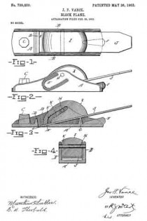
Figure 1 is a top plan view of my improved block-plane. Fig. 2 is a side elevation. Fig. 3 is a longitudinal mid-sectional elevation. Fig. 4 is a cross-sectional elevation.
In the specification similar reference letters indicate corresponding parts.
The metallic base or frame consists of the following structural parts: A is the base, from which rises two sides B B, that are joined by transverse ribs D and G. The former rib lies immediately in front of the opening E, through which the cutting edge of the blade J projects, and the rib G forms a support for said blade in the rear part of the frame and whereby the said blade is supported in a proper inclined plane. This inclined plane is a very essential feature of the invention, and to be more specific in describing it it is stated that the angle thereof is approximately not more than twelve degrees. With the cutting-blade held rigidly in such position by the means hereinafter described the work of the plane is rendered comparatively easy and effective.
C designates an integral projection rising from the front portion of the base A and upon which the index-finger of the operator rests.
F is a projection formed integral with the base and projecting beyond the rear end of the base. The object of this projection is to provide a suitable surface to be struck by a hammer or other implement in detaching the blade.
The sides B of the frame are provided on their outer surfaces with suitable grooves A”, which enable a suitable grip of the fingers in operating the plane.
That portion of the base A immediately in the rear of the blade-opening A is provided with a tapering surface A’ of a proper inclination to enable the blade to lie thereon at the angle hereinbefore specified.
H designates a round bar extending between the middle parts of the two sides B B and being rigidly secured in said sides, the position of such bar being substantially as indicated in the drawings.
I designates a combined grip and wedge block, preferably constructed of wood and having a specially-formed slot in the front portion thereof, which extends and terminates rearwardly on an angle, substantially as shown. In a more specific description of this feature K’ designates the beginning or forward end of this slot, which, it will be observed, commences in an upright manner from the lower or straight surface of the block and gradually curving and extending in an upward and rearward inclination K. This slot extends through the block from one side to the other and receives the cross-bar H. By means of said slot the wedge-block may be rigidly forced in contact with the upper surface of the cutting-blade by pressing said block forwardly after said slot enters the bar H. The lower surface of said block, it will be observed, is made flat to snugly fit against the blade. When the block is forced by the hand of the operator to the position shown in the drawings, Figs. 2 and 3, the cutting-blade J is very firmly held against the transverse rib G. The act of operating the plane will tend constantly to increase this wedge-like contact between said block and the blade, as it will be seen that the pressure exerted by the hand upon the block in operating the plane is in a forward direction or a direction to force the cross-bar H farther up and into the slot.
Having described my invention, I claim —
In a block-plane, a frame having upright sides with intervening cross-ribs one of which supports the blade, a cross-bar between the upper portions of said upright sides and rigidly connected thereto, in combination with a combined wedge and grip block having a slot therein adapted to receive said cross-bar, said slot extending from the lower face of said combined grip and wedge block in a vertical direction and terminating in a rearward and upward inclination, whereby the pressure exerted upon said block in the operations of the plane will tend to increase the rigidity of contact between said block and the blade, substantially as set forth.
In testimony whereof I affix my signature in presence of two witnesses.
JOHN P. VANCE.
Witnesses:
A. J. FIORINI,
CAROLYN M. THEOBALD.


