No. 848,364 – Multiple-Beading Plane (Paul Harding) (1907)

[paiddownloads id=”640″]848364


UNITED STATES PATENT OFFICE.

_________________

PAUL HARDING, OF LONG ISLAND CITY, NEW YORK.

MULTIPLE-BEADING PLANE.

_________________

848,364. Specification of Letters Patent. Patented March 26, 1907.
Application filed May 25, 1906. Serial No. 318,633.

_________________

To all whom it may concern:

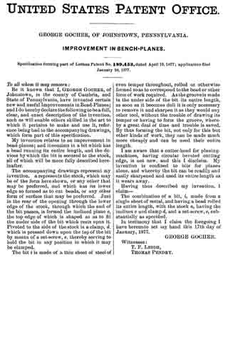
Be it known that I, PAUL HARDING, a citizen of the United States, and residing at Long Island City, in the county of Queens and State of New York, have invented certain new and useful Improvements in Multiple-Beading Planes, of which the following is a specification, such as will enable those skilled in the art to which it appertains to make and use the same.

This invention relates to hand-planes for use by carpenters in beading moldings or other woodwork; and the object thereof is to provide an improved device of this class having a plurality of beads of different styles or dimensions, whereby a single plane of the class specified may be used for making a variety of beads or a variety of moldings or for producing a variety of beads in woodwork of any kind or class.

The invention is fully disclosed in the following specification, of which the accompanying drawings form a part, in which the separate parts of my improvement are designated by suitable reference characters in each of the views, and in which —

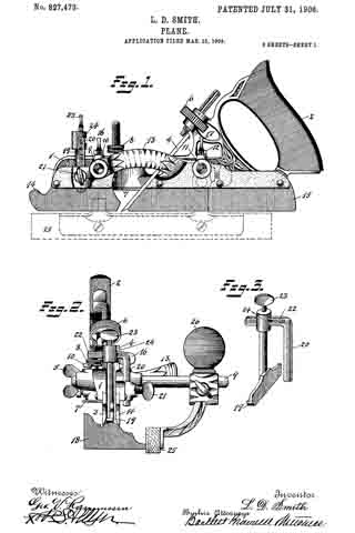
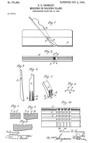
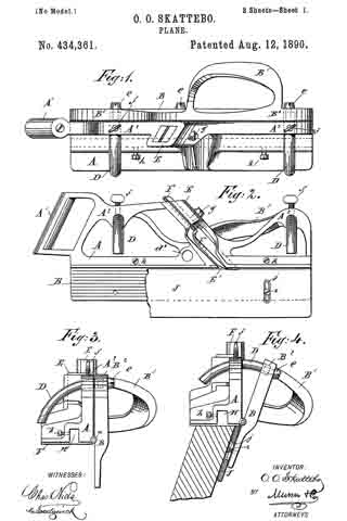
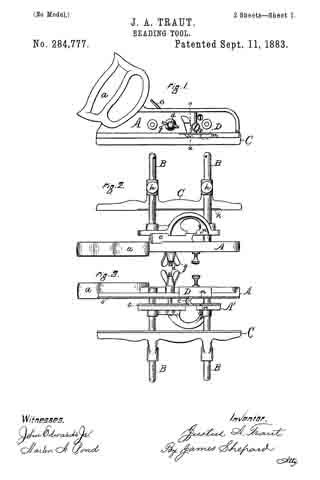
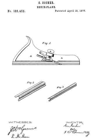
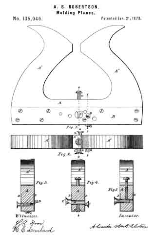
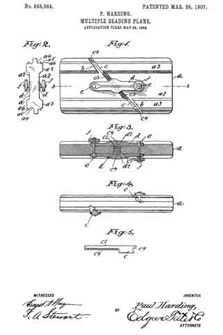
Figure 1 is a side view of my improved beading-plane; Fig. 2, an end view thereof; Fig. 3, a longitudinal section on the line 3 3 of Fig. 1; Fig. 4, a plan view, and Fig. 5 a side view, of one of the bits which I employ.

In the practice of my invention I provide an oblong flat block a, which constitutes the body of the plane, and said block is provided in the opposite side thereof with longitudinal wide grooves or spaces a2, whereby top and bottom thickened portions a3 are formed, said thickened top and bottom portions a3 being provided in their outer longitudinal faces with grooves a4, which are circular in cross-section, beads a5, and rabbet-grooves a6.

The block a, is provided in the opposite sides thereof and diagonally of the central portion thereof with grooves b, which extend through the thickened top and bottom portions a3 and also through the central portion of said block and in which are mounted bits c, two of which are placed in each side of the block, four bits in all being employed.

The bits c are provided with shanks c2, which overlap and extend across the central or body portion of the block and are provided in their outer sides with transverse grooves or recesses c3, forming corresponding teeth, and in the opposite sides of the body portion of the block are placed countersunk plates d, which are held in place by bolts e, provided at one end with thumb-and-finger nuts f, and the shanks c2 of the bits c are beveled on the sides in which the recesses are formed, and when two of said shanks are placed together in the opposite sides of the block they form a projecting longitudinal rib, as shown at c4, and the plates d are provided with corresponding transverse diagonal grooves d2, and in this way the bits c may be securely locked in the block a. As shown, the bolts e are preferably passed through the plates d and the central portion of the block a in opposite directions; but the placing of said bolts in this position is not absolutely necessary, and the thumb-and-finger nuts f may both be on the same side of the block a, if desired. In order to adjust the bits c, the thumb-and-finger nuts f or one of them is loosened and a suitable tool is inserted into the recess c3 of the shanks of said bits, and said bits are moved or adjusted to any desired extent, after which the thumb-and-finger nut or nuts are tightened, so as to hold the bits in the desired position.

In the drawings forming part of this specification the bits c are all of the same style, and the cutting edges c4 thereof are all of the same form, but of different dimensions, and the beads and grooves formed by means of my improved beading-plane, as shown and described, will all be of the same style, but will vary in transverse dimensions, the shape in cross-section of said beads being indicated by the shape of the beads and grooves a4, a5, and a6 shown in Fig. 2. It will be apparent, however, that the cutting edges of the bits may be of any desired form or shape, and the grooves and beads a4, a5, and a6 shown in Fig. 2 will vary to correspond therewith, and the beads and grooves formed by the plane will depend upon the style of these features of the construction.

Having fully described my invention, what I claim as new, and desire to secure by Letters Patent, is —

1. A beading-plane comprising an oblong flat body member having longitudinal grooves and beads in the top and bottom thereof, and two bits mounted in the opposite sides of said member and diagonally thereof and in diagonal grooves formed therein, the cutting edges of said bits extending in opposite directions, and means for locking said bits in position, consisting of plates bolted longitudinally of the opposite sides of said body member and ranging transversely of the shanks of said bits.

2. A beading-plane comprising an oblong flat body member having grooves arranged diagonally in the opposite side portions thereof and extending through the top and bottoin faces thereof, two bits: mounted in the grooves in said opposite side portions of said ineniber and provided with overlapping shanks and the cutting edges of which extend in opposite directions, and means for locking said bits in position, consisting of plates secured longitudinally of the central body portion and in the opposite sides of said member transversely of the shanks of said bits.

In testimony that I claim the foregoing as my invention I have signed my name in presence of the subscribing witnesses.

PAUL HARDING.

Witnesses:
JAMES McMAHON,
WALTER D. WARD.

No. 830,541 – Bench-Plane (Justus A. Traut) (1906)

[paiddownloads id=”635″]830541


UNITED STATES PATENT OFFICE.

_________________

JUSTUS A. TRAUT, OF NEW BRITAIN, CONNECTICUT, ASSIGNOR TO STANLEY RULE &
LEVEL COMPANY, OF NEW BRITAIN, CONNECTICUT, A CORPORATION OF CONNECTICUT.

BENCH-PLANE.

_________________

830,541. Specification of Letters Patent. Patented Sept. 11, 1906.
Application filed May 26, 1906. Serial No. 318,812.

_________________

To all whom it may concern:

Be it known that I, JUSTUS A. TRAUT, a citizen of the United States, residing at New Britain, county of Hartford, Connecticut, have invented certain new and useful Improvements in Planes, of which the following is a full, clear, and exact description.

My invention relates to improvements in tools, and particularly planes for carpenters’ and joiners’ use.

The object of the invention is to provide a stop or gage for limiting the cutting depth and steadying the plane when in operation.

Various gages and stops have previously been employed in tools of this character, but for some classes of work they fail to give proper support to the plane when in operation.

The preferred form of the invention is illustrated in the accompanying three sheets of drawings.

Figure 1 is an end view of a plane embodying the improvements of my invention. Fig. 2 is a detail perspective view of a part of the gage. Fig. 3 is a side view of a plane with gage attached. Fig. 4 is a bottom plan view.

1 is the main body or handle member.

2 is the plane-iron having a suitably-formed cutting edge in accordance with the cross-section of the product desired. This iron is clamped in place by a suitable mechanism, such as 3, and may be adjusted by a suitable mechanism, such as 4.

5 and 6 are cross-rods clamped to the body in a suitable manner.

7 is an auxiliary clamping and supporting member for the plane-iron, which is clamped on the rods 5 and 6 by suitable mechanism.

8 is a fence customarily employed with planes of this character for guiding it laterally in operation. The main and auxiliary portions of the plane are provided with guide-flanges 9 and 10. A plane-iron of any width may be employed with this tool, the body and auxiliary members being adjusted laterally with respect to one another.

11 is the gage or stop the use of which my invention particularly contemplates. This stop has laterally-extending arms 12 and 13, which project through openings, such as 14 and 15, in the guide-flanges 9 and 10.

16 is a screw-threaded post having a foot 17, to which the gage 11 is secured by means of screws 18 and 19.

The post and gage may be vertically adjusted by the screw 20 and clamped in position by the screw 21. When the gage is being vertically adjusted, it is guided and prevented from rotating on its post by reason of its construction and coaction with the guide-flanges 9 and 10. By reason of the bearing-surfaces provided by the arms 12 and 13 in front and in rear ofthe cutting-iron and the lateral extensions outside of each guide-flange the tool is prevented from tilting forward and back or sidewise when in operation.

The gage may be adjusted to suit the depth of cut desired and may be readily removed upon releasing the screws 18 and 19, in which event the foot 17 acts as a gage, which maybe adjusted for work requiring the gage only on one side. The arms 12 and 13 being formed in one piece with the main body 11 of the gage, the entire bearing area remains in a single plane and is consequently adjusted vertically with uniformity in front and in rear of the plane-iron. This is an advantage which would not be present were the two arms 12 and 13 carried by separate adjusting-posts.

What I claim is —

1. In a plane, a body, auxiliary members having depending guide-flanges with passages in said flanges, and a gage extending laterally through said passages.

2. In a plane, a body and auxiliary members laterally adjustable with relation to one another and adapted to support a plane-iron, a vertically-adjustable post, and a gage carried thereby having members extending in front and in the rear of the plane-iron position and laterally beyond the edges of the plane-iron.

3. In a plane, a body having a depending flange, a plane-iron carried by the body, an adjustable post carried by the body, and a gage carried by said post having an arm extending through the flange in front of the plane-iron.

4. In a plane, a body, an iron clamped thereto, a depending iiange from said body, an auxiliary member laterally adjust able with respect thereto, a depending guide-flange carried by said auxiliary member, and a vertically-adjustable gage in the rear of the plane-iron position extending through said flanges.

5. In a plane, main and auxiliary sections, depending flanges carried thereby, a plane-iron held between said sections, a vertically-adjustable post having a foot, and a gage removably secured to said foot and having an arm extending through said flanges.

6. In a plane, main and auxiliary sections, depending flanges carried thereby, a plane-iron held between said sections, a vertically-adjustable post having a foot, and a gage removably secured to said foot and having arms extending through said flanges in front and in the rear of the plane-iron.

7. As an article of manufacture, a plane-gage attachment comprising a body, means of attachment to a plane, and laterally-extending arms carried by the body spaced apart from each other and lying in the same plane with the body.

JUSTUS A. TRAUT.

Witnesses:
W. J. WORAM,
H. S. WALTER.

No. 827,473 – Plane (Lewis Dorus Smith) (1906)

[paiddownloads id=”634″]827473


UNITED STATES PATENT OFFICE.

_________________

LEWIS DORUS SMITH, OF PORT HURON, MICHIGAN, ASSIGNOR TO
STANLEY RULE AND LEVEL COMPANY, A CORPORATION OF CONNECTICUT.

PLANE.

_________________

827,473. Specification of Letters Patent. Patented July 31, 1906.
Application filed March 15, 1904. Serial No. 198,203.

_________________

To all whom it may concern:

Be it known that I, LEWIS DORUS SMITH, a citizen of the United States, residing at Port Huron, county of St. Clair, State of Michigan, have invented certain new and useful Improvements in Planes, of which the following is a full, clear, and exact description.

My invention relates to improvements in planes, and particularly to a plane which is adapted to carry any one of a large variety of cutters or plane-irons. A plane of the same general class is shown in the United States Letters Patent No. 532,84.

The object of my invention is to construct a plane which shall be efficient and readily interchangeable and adjustable for different classes of work. I have also sought to make the construction as simple as possible, so that the adjustments and interchanges may be effected easily, and the cost of manufacture may be reasonable. I have also sought to construct a plane which shall be useful in connection with classes of work hitherto impossible to planes of this type.

A plane embodying my invention is shown in the accompanying single sheet of drawings. Two parts of the plane are adjustable laterally with relation to one another and adapted to carry a plane-iron. Between the two adjustable portions is located a gage for limiting the cutting depth of the iron. This gage is adjustable vertically and laterally and is readily removable. When desired , an auxiliary guide may be employed.

Figure 1 is a side elevation of a plane embodying the improvements of my invention, a portion of an auxiliary guide being shown dotted. Fig. 2 is a front elevation of a plane embodying the improvements of my invention shown as in operation. Fig. 3 is a detail perspective view of the center gage and attachments. Fig. 4 is a bottom view of the complete plane. Fig. 5 is a vertical sectional view on the plane of the gage-support.

1 is the main stock portion having a handle 2 and a guide-blade 3.

4 is a plane-iron, having a suitable cutting edge — as, for instance, a “hollow.”

5 is a screw of suitable construction for clamping the plane-iron to the main stock 1.

6 is an adjusting screw for varying the cutting depth.

7 is a gage carried at the outer side of the main stock and adjustable in a suitable manner by means of the screw 8.

9 is a guide-rod which extends laterally from the main stock 1 and may be secured thereto by means of the screw 10. 11 is a similar guide-rod at the rear, which may be attached to the main stock by means of the screw 12.

13 is what may be conveniently termed a “sliding section,” having the guide-blades 14 and 15 corresponding to the guide-blades 3 and 30 of the main stock. This section 13 is adjustable laterally on the guide-rods 9 and 11 to and from the main stock 1. 16 and 17 are thumb-screws for holding it in the desired position. In the instance herein shown the distance from the outer surface of the guide-blade 3 to the outer surface of the guide-blade 14 is approximately equal to the width of the cutter or plane-iron 4.

18 indicates a section of a molding, a portion of which has just been formed by the cutter 4. It will be obvious to one acquainted with this art that cutters of many different forms may be employed with a tool of this character to shape a molding, as desired.

19 is a gage for steadying the plane and limiting the cutting depth of the plane-iron 4. 20 is a post which is vertically adjustable in a recess in the outer surface of the sliding section 13. 21 is a thumb-screw for securing it in place. 22 is a horizontal member for connecting the adjustable post 20 and the gage 19. In this instance the horizontal bar is carried by the post 20. 23 is a thumb-screw which clamps the gage to the horizontal cross-bar 22. The gage preferably has an enlarged portion 24 at the top, which is open at the rear, so that the gage may be removed by simply loosening the screw 23 and slipping the gage forward. The gage in this way may be removed without being obstructed by the guide-rod 9. By this construction the center gage 19 may be adjusted vertically and also laterally, so as to provide for different widths and conformations of cutters.

25 is a longitudinal guide or fence which may be carried by the longitudinal guide-rods 9 and 11 and adjustable laterally thereon. 26 is a handle for convenience in operation. Such a guide or fence is not necessary in all kinds of work; but in forming a molding, as herein illustrated, it is advantageous.

What I claim is —

1. In a plane, the combination of a handle member, a sliding section member adjustable relatively thereto, a laterally-projecting lug carried by one of said members and having a vertical passage-way, a post passing through and vertically adjustable in said passage-way, a laterally-extending thumb-screw passing through said lug for coacting with said post, and a center gage located between said members and means for supporting said gage from said vertical post.

2. A plane-gage attachment of the character described comprising the combination of two substantially parallel rods, a shoe member carried by one of said rods, a connecting member having one endf fixedly secured to one rod and an adjustable clamping means carried by the other rod for engagement with said member and having an open horizontal slot, substantially as described for the purpose specified.

3. A plane-gage attachment of the character described, and for the purpose specified, comprising the combination of two substantially parallel rods spaced apart from each other, a shoe member carried by one of said rods, a laterally-projecting connecting member having one end fixedly secured to one of said rods, the other rod being laterally adjustable upon the connecting member of the first rod, and means for clamping the second rod upon said connecting member.

Signed at Port Huron, Michigan, this 5th day of March, 1904.

LEWIS DORUS SMITH.

Witnesses:
S. V. JONES,
LEWIS ATKINS.

No. 778,921 – Plane (Justus A. Traut) (1905)

[paiddownloads id=”612″]778921


UNITED STATES PATENT OFFICE.

_________________

JUSTUS A. TRAUT, OF NEW BRITAIN, CONNECTICUT, ASSIGNOR TO THE STANLEY RULE & LEVEL COMPANY, OF NEW BRITAIN, CONNECTICUT, A CORPORATION OF CONNECTICUT.

PLANE.

_________________

SPECIFICATION forming part of Letters Patent No. 778,921, dated January 3, 1905.
Application filed April 27, 1904. Serial No. 205,115.

_________________

To all whom it may concern:

Be it known that I, JUSTUS A. TRAUT, a citizen of the United States, residing at New Britain, in the county of Hartford, State of Connecticut, have invented certain new and useful Improvements in Planes, of which the following is a full, clear, and exact description.

My invention relates to improvements in planes and particularly to planes, in which cutters of various sizes and shapes may be interchangeably employed.

The object of the invention is to provide a construction in which interchanges of cutters may be effected readily and quickly and the operation of the same made reliable and efficient. I have also sought to employ as few parts as possible and to make the construction as economical as its large variety of functions make feasible.

The construction of my invention in the particular form as shown in the drawings consists of a main body portion and a relatively movable section between which the cutting-iron is secured and held in place. Adjustable and interchangeable sole portions are provided by means of which the plane may be guided and the cutting depth regulated with any form of cutting-iron. These adjustable sole portions also support and steady the plane-iron and permit the user to vary the size of the throat or opening in front of the cutting edge.

The details of construction will be more plainly seen on an inspection of the accompanying single sheet of drawings.

Figure 1 is a side elevation of a plane embodying the improvements of my invention. Fig. 2 is a front elevation of the same with the addition of adjustable auxiliary guide. Fig. 3 is a perspective view of a cutting-iron. Fig. 4 is a perspective view of the adjustable and interchangeable sole portions for employment with the plane of my invention.

1 indicates a main body or stock portion of the plane having a guide-blade 2.

3 is a handle which is conveniently provided.

4 is the plane-iron or cutter, which has its cutting edge formed to correspond with the outline of the work which it is desired to turn out.

5 is a suitable clamping-screw for securing the cutter in place.

6 is a screw for adjusting the cutting depth of the plane-iron.

7 and 8 are rods which extend from the body portion of the plane.

9 and 10 are screws for clamping in position.

11 is a sliding section which is upon the rods 7 and 8.

12 and 13 are thumb-screws for clamping the section in place at the distance desired from the main body portion.

14 and 15 are flanges to the front and rear of the throat of the plane which extend downward. The plane-iron when clamped in place is partially supported by the rear flange.

16 and 17 are portions of a sole which is provided to correspond with the shape of the cutter employed to limit the cutting depth and to guide and direct the plane in its operation. These sole portions are formed, preferably, of wood.

18 indicates two screws which take into the sole member 16 for clamping it to the forward flange 14. The flange is preferably provided with keyhole-openings, as shown, so that the sole portion may be removed without entirely removing the screws, it simply being necessary to loosen the screws, slide the sole forward, when the screws may be readily drawn through the enlarged portion. The rear flange 15 is provided with oppositely-positioned keyhole-openings, and the screws 19 coact therewith to clamp the rear sole portion 17 in position. Both of the sole portions may be adjusted front and rear, so as to vary the size of the throat in front of the cutter to bring the rear sole portion up so as to reinforce the cutter and prevent it from chattering or to remove the parts, as may be desired.

20 indicates a section of a molding being cut by a cutter, as shown in the drawings. The form of outline produced will of course depend upon the cutter employed. With my improved invention in use any form of cutter may be employed, it simply being necessary to make use of correspondingly-formed sole portions.

21 indicates a member which may be provided to slide on the rods 7 and 8 and carry an auxiliary guide 22 for fixing the distance of the cutter from the edge of a board, molding, or the like.

23 is a handle which is conveniently provided on this fence portion which serves as a rest for the left hand.

The advantages of my construction will be particularly apparent to those skilled in the manufacture of woodworking-tools and in their use. It greatly reduces the number of parts necessary for a wide variety of work and the expense of the same.

What I claim is —

1. In a plane the combination of a main body member, a member laterally adjustable relatively thereto having flanges projecting downward, said flanges having horizontal openings with enlarged ends, a cutter having an irregularly-shaped edge, a sole member for each of said flanges corresponding in shape to said cutter, and screws for removably securing said sole members to said flanges.

2. In a plane the combination of a main body member, a second member slidable laterally relatively thereto, a pair of flanges projecting downwardly from said slidable member and having an opening between the same, a sole portion carried by each of said flanges, and means for adjusting said sole portions, substantially as described.

3. In a plane, the combination of a body member, a second member laterally adjustable with relation thereto and adapted with said first member to support a plane-iron, a pair of flanges carried by said second member, one in front and the other in the rear, each of said flanges having a plurality of openings elongated liorizontally, the openings in said forward flange being enlarged on their forward ends, the openings in the rear flange being enlarged on their rear ends and a pair of removable sole portions with means coacting with said flanges and the elongated openings therein for securing said sole portions to said flanges.

Signed at New Britain, Connecticut, this 25th day of March, 1904.

JUSTUS A. TRAUT.

Witnesses:
W. J. WORAM,
ROBERT N. PECK.

No. 771,463 – Molding Or Beading Plane (Charles C. Crossley) (1904)

[paiddownloads id=”609″]771463


UNITED STATES PATENT OFFICE.

_________________

CHARLES C. CROSSLEY, OF NEW BRITAIN, CONNECTICUT.

MOLDING OR BEADING PLANE.

_________________

SPECIFICATION forming part of Letters Patent No. 771,463, dated October 4, 1904.
Application filed February 13, 1904. Serial No. 193,362. (No model.)

_________________

To all whom it may concern:

Be it known that I, CHARLES C. CROSSLEY, of New Britain, in the county of Hartford and State of Connecticut, have invented a new and useful Improvement in Molding or Beading Planes; and I do hereby declare the following, when taken in connection with the accompanying drawings and the letters of reference marked thereon, to be a full, clear, and exact description of the same, and which said drawings constitute part of this specification, and represent, in —

Figure 1, a side view of a plane containing a cutter constructed in accordance with my invention; Fig. 2, a bottom view thereof; Fig. 3, a side view of the lower end of the cutter detached; Fig. 4, a front view of the same; Fig. 5, a perspective view of the cutter looking at the rear; Fig. 6, an outline of the cutting edge; Fig. 7, a sectional view of a block showing a single cut; Fig. 8, a similar view with two cuts; Fig. 9, a similar view with three cuts; Fig. 10, a plan view of a block showing cuts made at right angles.

This invention relates to an improvement in molding or beading planes, and particularly to the cutters therefor, the object of the invention being to so form the cutter that it may be used in stocks of ordinary construction and by which beads may be cut in every direction and, if desired, at angles to each other; and the invention consists in the construction as hereinafter described, and particularly recited in the claim.

In carrying out my invention I employ a stock A, which may be a center-bead stock, as shown, or a side-bead stock, having the usual mortise B for the reception of a cutter C, which is held in place by the usual wedge D. The operating edge of the cutter has a central half-round portion E, horizontal lower cutters F, and upwardly-extending side cutters or lips G, the end of the cutter being so formed that the cutting edges of the lower critters F are in rear of the cutting edge of the center portion E, whereby a drawing cut is made which assists in cutting smoothly and in any direction as regards the grain of the wood.

The plane is operated in the usual manner and if used upon the surface of wood the first cut will form a half-round bead H, with grooves I on opposite sides thereof, the outer walls of the grooves being straight, as shown in Fig. 7. If two beads are desired, the plane is moved to one side, so that one of the cutters F and the lip G ride in the groove formed at one side of the half-round bead H, which forms a guide for the plane and allows the central portion of the cutter to form a second half-round bead J and a groove K at one side, having a straight side wall, as shown in Fig. 8, or three beads may be formed, as shown in Fig. 9, and this can be continued indefinitely. In Fig. 10 of the drawings I have shown beads L and M crossing each other at right angles, and, as before stated, with my improved cutters these beads may be formed in any direction.

Having fully described my invention, what I claim as new, and desire to secure by Letters Patent, is —

In a plane, the combination with the stock, of a cutter having a central rounded cutting edge, straight cutters on opposite sides of the center and in rear thereof, and side cutters or wings extending upward and forward therefrom, substantially as described.

In testimony whereof I have signed this specilication in the presence of two subscribing witnesses.

CHARLES C. CROSSLEY.

Witnesses:
AARON DANIELSON,
CHAS. A. ERICSON.

No. 538,937 – Combination-Plane (Jacob W. Tripp) (1895)

[paiddownloads id=”514″]538937


UNITED STATES PATENT OFFICE.

_________________

JACOB W. TRIPP, OF SALT LAKE CITY, UTAH TERRITORY.

COMBINATION-PLANE.

_________________

SPECIFICATION forming part of Letters Patent No. 538,937, dated May 7, 1895.
Application filed August 9, 1894. Serial No. 519,912. (No model.)

_________________

To all whom it may concern:

Be it known that I, JACOB W. TRIPP, of Salt Lake City, in the county of Salt Lake and Territory of Utah, have invented a new and Improved Combination-Plane, of which the following is a full, clear, and exact description.

The object of the invention is to provide a new and improved plane, which is comparatively simple and durable in construction, arranged for universal adjustment to enable the operator to conveniently plane straight or curved work, such as stair rails, on all sides, and for molding, fitting, plowing, tonguing and grooving, rabbeting and other purposes, also to form beads, fillets, &c.

The invention consists principally of a stock adapted to receive a removable wooden sole piece shaped to conform to the curved or straight surface to be planed.

The invention further consists in a bit having gear teeth adapted to be engaged by a segmental lever, for shifting the said bit into proper position.

The invention also consists in an auxiliary guide stock pivoted on an adjustable arm held on the main stock.

The invention also consists in certain parts and details, and combinations of the same, as will be fully described hereinafter, and then pointed out in the claims.

Reference is to be had to the accompanying drawings, forming a part of this specification, in which similar letters of reference indicate corresponding parts in all the views.

Figure 1 is a side elevation of the improvement. Fig. 2 is a plan view of the same. Fig. 3 is a sectional side elevation of the improvement on the line 3 3 of Fig. 2. Fig. 4 is an enlarged transverse section of the bit-guide, the section being taken on the line 4 4 of Fig. 3. Fig. 5 is a transverse section of the improvement on the line 5 5 of Fig. 1. Fig. 6 is a sectional rear elevation of part of the improvement on the line 6 6 of Fig. 5. Fig. 7 is a side elevation of the improvement, showing a modified form of sole-piece. Fig. 8 is a perspective view of a modified form of guide-piece for the auxiliary guide-stock. Fig. 9 is a perspective view of a modified form of sole-piece in front of the cutting-bit. Fig. 10 is a sectional plan view of part of the improvement on the line 10 10 of Fig. 7. Fig. 11 is a rear elevation of the auxiliary guide and adjacent parts. Fig. 12 is a side elevation of the improvement arranged with a straight wooden sole-piece, part of which is broken out. Fig. 13 is a sectional plan view of the same on the line 13 13 of Fig. 12. Fig. 14 is an inverted plan view of the bit. Fig. 15 is a plan view of the same. Fig. 16 is a face view of a combination quick cutter and blank. Fig. 17 is a face view of a modified form of fastening for the quick cutter, and Fig. 18 is a sectional plan view of the same on the line 18 18 of Fig. 17.

The improved plane is provided with the metallic stock A, having an integral handle A’, and a bit plate A2 extending in an inclined direction, as plainly shown in Figs. 1 and 3, and fastened by screws or other means to the stock A and handle A’. On the under side of the stock A, is adapted to be secured by screws orother means, a sole piece B, having its bottom made in various shapes according to the article to be planed. The sole piece is made of wood, and is shaped at its under side to correspond to the shape of the article to be planed, as will be readily understood by reference to Fig. 1, or is made straight at its under side for planing straight surfaces of different shapes, as illustrated in Fig. 12.

On the lower end of the cap C is secured a sole piece B’, forming a continuation of the sole piece B, and shaped according to the article under treatment, that is, either curved at the under side, as shown in Fig. 1, or straight as illustrated in Figs. 9 and 12. The pressure plate or cap C for the plane, is adapted to engage and hold the cutting bit D on the bit plate A2.

In order to shift the bit D, I form the top surface thereof at the upper end with rack teeth D’ adapted to be engaged by the teeth E’ of a segmental lever E, formed with a slot E2 adapted to engage a pin C’ extending transversely in the pressure plate C, and through an aperture C2 therein, as will be readily understood by reference to Fig. 3. Now when the pressure plate C is in place, the operator inserts the segmental lever E in the aperture C2, so that the pin C’ forms a fulcrum for the said lever, and the teeth E’ of the latter engage the rack teeth D’ of the bit D. When the operator swings the lever E either up or down, then the teeth E’ shift the bit D down or up, so as to adjust the cutting edge of the bit according to the under side of the sole piece B. After proper adjustment is made of the bit D, then the segmental lever E is again removed from the aperture C2 and the pin C’. The pressure plate or cap C is held from sliding by dowels F, F’, which project at right angles from the bit plate A2. See Fig. 3. To clamp the bit in place on the bit plate A2, I provide a screw rod F2, secured in the bit plate A2, parallel to the dowels F F’. The screw rod F2 is provided with the smooth piece F3, extending through the bit slot D2 and the cap C. The reduced end F4 of the screw rod F2 engages a removable block G, fitting under the head F5 of the said screw rod, and on the sides of the said block G is fulcrumed a cam lever G’, formed near its outer end with an opening G2 adapted to fit over the outer end of the dowel pin F’, whenever the said cam lever is in a closed position, as shown in Figs. 1, 3, and 12. The cam is formed on the fulcrumed end of the lever G’, and engages a wearing plate G4 held on the pressure plate C, so that when the lever G’ is swung inward, then the cam portion of the said lever presses on the wearing plate G4, to raise the block G, and to securely press the latter against the under side of the head F5 of the screw rod F2, whereby the pressure plate C is firmly pressed inward onto the bit D, to clamp the latter securely in position. The wearing plate G4 can be dispensed with in case the cap C is made of a hard material.

When the lever G’ is swung outward into the position shown in dotted lines in Fig. 3, then the cam end of the lever releases the block G from pressing on the head F5, thereby loosening the pressure plate C sufliciently to remove the cutting bit D as may be desired. In order to properly guide the bit D, I provide the under side thereof with a longitudinal recess D3, see Figs. 3 and 14, engaged by a lug A3 formed or secured on the bit plate A2.

On the lower end of the cap C, and abutting on the face of the bit D, is arranged an adjustable plate C4, formed with a longitudinally-extending shoulder C5 fitting into a correspondingly shaped groove in the cap or pressure plate C, as plainly shown in Fig. 4. A screw C6 serves to hold the adjustable plate C4 in place on the pressure plate C, the said screw passing through a longitudinally-extending slot C7 formed in the adjustable plate C4. By the arrangement described, the plate C4 can be readily adjusted on the pressure plate C, by loosening the screw C6, and then shifting the said adjustable plate C4 so that its lower end is as close down to the cutting edge of the bit as desirable, to permit of cutting in cross-grained wood without danger of tearing it or leaving a rough surface.

On the rear face of the stock A, is held adjustably a block H, provided with an obliquely-extending slot H’, through which passes a screw H2 screwing in the stock A, as teaser indicated in Figs. 6 and 7. A shoulder H4, see Fig. 10, formed on the back of this block H engages a correspondingly shaped groove A5 in the rear face of the bit plate A2, the said groove A5 being arranged parallel or in alignment with the slot H’, so as to permit of shifting the block H in an oblique direction on the stock, as required. On the back of the block H is formed a vertical recess or groove H3 (see Figs. 2 and 5), in which is held adjustable a quick cutter or bit I, for cutting the sides or edges of the wood under treatment, as plainly illustrated in Figs. 5 and 7. The quick cutter I, may be held in place on the block H, either by a screw I’, as shown in Fig. 5, or by making it dovetailed in cross section and clamping it in position at one edge by a cap H7 adapted to be fastened to the block H by a screw H8, as shown in Figs. 17 and 18. Instead of the cutter or bitI, I may place a blank I3 in the said groove H3, see Fig. 12, and the cutter I and blank I3 may be combined in a single piece, as illustrated in Fig. 16. The blank I3 is provided with a row of apertures, one of which is adapted to be engaged at a time by the set screw I’, but the blank may also be held in place by the cap H7 above mentioned. This blank I3, when used, prevents the shavings from accumulating in the plane throat and choking the plane, and is especially serviceable when cutting deep slots or grooves with the bit D, or other bits that may be used.

On the lower end of the block H is pivoted at J’, the auxiliary guide stock J, extending transversely, as plainly shown in the drawings, and carrying at its lower end an adjustable plate K, engaged by a set-screw K’ passing through a slot J2 extending longitudinally in the auxiliary guide-stock J. By this arrangement the plate K can be adjusted laterally in the guide stock according to the thickness or width of the wood under treatment. The screw K’ is adapted to engage one of a series of apertures K2, K3, K4, in the plate K, so as to increase the range of adjustment of the said plate K on the said guide-stock J.

On the front end of the plate K is arranged a foot-piece K5, made of wood or other suitable material, and shaped to correspond to the shape of the wood to be planed, as indicated in Figs. 5 and 8. The foot-piece K5 shown in Fig. 8 is more especially designed for use on twisted and crooked work. The foot-piece K5 is opposite the front sole-piece B’, secured to the under side of the shavings cup C9, as will be readily understood by reference to the dotted lines in Fig. 1, the said foot-piece also extending rearwardly a suitable distance, so that its rear end is about opposite the cutting edges of the bits D and I.

On one side of the auxiliary guide stock J is fitted to slide transversely, a block L, having a longitudinally extending groove L2 engaged by a set screw L’ screwing in the auxiliary guide-stock J, the screw L’ thus admitting of a right or left movement of the said block, and the screw is adapted to engage one of a series of tap apertures J3 in the auxiliary guide-stock J. See Fig. 11. A link N, pivotally connects this block L with a stud N’ secured on the block H, so that the upward and downward swinging motion of the auxiliary guide-stock is limited, but any desired adjustment can be made by adjusting the screw L’ in one of the series of tap apertures J3 in the auxiliary guide stock J. By this arrangement the auxiliary guide-stock J can be moved in a tilted position according to the wood under treatment, or the main stock A may be inclined, as shown in dotted lines in Fig. 5.

Now it will be seen that with the device described, almost any desired form of molding can be planed as the tool is universall adjustable for all kinds of work of any class desired.

Having thus described my invention, I claim as new and desire to secure by Letters Patent —

1. A plane having its body composed of two separable parts, to wit: a stock and a pressure-plate, in combination with a bit located between said parts, substantially as set forth.

2. The combination of a main stock having a bit-plate and a bit mounted thereon and provided with a series of rack teeth on its upper face, a pressure plate arranged over the bit and provided with a recess extending through it adjacent to the rack teeth of the bit, a rod extending transversely of said recess a lever with its bifurcations embracing said transverse rod and engaging the rack teeth in the bit, whereby the same may be adjusted, and means for locking said bit fast to the bit plate, substantially as set forth.

3. The combination of a main stock having a bit plate and a bit mounted thereon and provided with a series of rack teeth on its upper face, a pressure plate arranged over the bit and provided with a recess extending through it adjacent to the rack teeth of the bit, a rod extending transversely through said recess, a bifurcated lever adapted to be arranged in said recess with its bifurcations on opposite sides of said transverse rod and engaging the rack teeth in the bit, whereby the same may be adjusted, a screw rod connected at one end to the bit plate with its other end extending through the pressure plate, and a lever connected to the extremity of said screw rod and provided with a cam adapted to bear on said pressure plate, whereby the bit may be clamped in place, substantially as set forth.

4. A plane having its body composed of two separable parts to wit: a stock and a pressure plate, in combination with removable sole-pieces secured to said parts, substantially as set forth.

5. The combination of a main stock having a bit, a plate H adjustably connected to said stock and also provided with a bit, said plate H being adapted to be moved in a direction parallel to the direction in which the bit on the main stock moves, substantially as set forth.

6. The combination of a main stock having a bit, a plate H, adjustably connected to the said stock and adapted to be moved in a direction parallel to the direction in which the bit on the main stock moves, the bit I adjustably mounted on said plate H, and an adjustable lower portion for said plate H, adapted to form a lateral guide for the main stock, substantially as set forth.

7. The combination of a main stock having a bit, a plate H adjustably connected to the said stock and adapted to be moved in a direction parallel to the direction in which the bit on the main stock moves, a bit adjustably arranged between said plate H and the main stock, and a clamping device for said bit, substantially as set forth.

8. A plane having its body composed of two parts, to wit: — a stock and a pressure-plate, one part having projecting dowel pins and the other part having sockets to receive the dowel-pins, in combination with a bit located between said parts and provided with slots to receive said dowel pins, substantially as set forth.

9. A plane having its body composed of two parts, to wit: — a stock and a pressure-plate, one part having dowel pins and the other part having perforations for the passage of the dowel pins, in combination with a bit located between the two parts, and a clamping device mounted on the perforated part and adapted to clamp the two parts together, whereby said bit is held in place, substantially as set forth.

10. A plane having its body divided vertically into two parts, one part being a stock and the other part being a pressure-plate, dowel-pins projecting from one part, the other part being perforated for the passage of the dowel-pins, a bit located between the parts and having slots for the passage of the dowel-pins, and a clamping device mounted on the perforated part and engaging the dowel-pins of the other part, and adapted to clamp the bit in place between the two parts, substantially as set forth.

11. A plane having its body composed of two parts, to wit: a stock and a pressure-plate, each provided with a sole-piece, a bit located between the two parts, and a clamping device adapted to clamp said parts together, whereby the bit is held in place, substantially as set forth.

JACOB W. TRIPP.

Witnesses:
CHARLES G. CARTER,
C. H. STEBBINS.

No. 434,361 – Plane (Ole O. Skattebo) (1890)

[paiddownloads id=”464″]434361


UNITED STATES PATENT OFFICE.

_________________

OLE O. SKATTEBO, OF HANNAFORD, NORTH DAKOTA,
ASSIGNOR OF ONE-HALF TO JORGEN HANSON, OF SAME PLACE.

PLANE.

_________________

SPECIFICATION forming part of Letters Patent No. 434,361, dated August 12, 1890.
Application filed March 8, 1890. Serial No. 343,098. (No model.)

_________________

To all whom it may concern:

Be it known that I, OLE O. SKATTEBO, of Hannaford, in the county of Griggs and State of North Dakota, have invented a new and Improved Plane, of which the following is a full, clear, and exact description.

My invention relates to improvements in carpenters’ planes; and the object of my invention is to provide a plane that will be equally efficient as a square or bevel plane, and that may be readily converted from one to the other, and also to provide a plane in which a great variety of tools may be inserted, so that the plane maybe used for matching, rabbeting, grooving, rounding, beading, and the like.

To this end my invention consists in a plane constructed substantially as hereinafter described and claimed.

Reference is to be had to the accompanying drawings, forming a part of this specification, in which similar letters of reference indicate corresponding parts in all the figures.

Figure 1 is a plan view of the plane; Fig. 2, a side elevation of the same with a portion of the guide-plate broken away; Fig. 3, an end view of the device as adjusted for a square plane, but with the guide-strip removed; Fig. 4, an end view of the same adjusted for a bevel-plane; Fig. 5, an end view of the plane adjusted for rabbet-work; Fig. 6, a side elevation of one of the separable parts of the plane with a portion of one hinge in section; Fig. 7, a detailed view of the pintle of the plane-hinges; Figs. 8 and 9, side elevations of the strips used for matching and rabbeting; Fig. 10, a transverse section on the line x x, of Fig. 8; Fig. 11, a detail view in elevation of the grooving-knife; Fig. 12, a perspective view of the grooving-guide; Fig. 13, a perspective view of the rounding or molding guide; Fig. 14, a front elevation of a corresponding knife for same, and Fig. 15 a perspective view of a ripping-guide.

The body or frame of the plane consists of two longitudinally-separable parts A and B, which are so hinged together by hinges a, near the ends thereof, that they may be placed at various angles with each other. The hinges a are attached to the inner edge of the part A, which carries the planer-knives, and to the upper edge of the part B, so that when the parts are shut closely together, the part B will shut against theinner edge of the part A, so as to project downwardly at right angles with the same. The hinges a are also provided with a removable pintle b, which fits in the knuckles a’ of the hinges, and which is screw-threaded at the end to engage a similar thread upon the interior of the inner knuckle of the hinges, so that the pintle may be easily removed and the parts A and B of the frame separated.

The parts A and B are each provided with a suitable handle A’ B’, by which the plane may be pushed or pulled, as the case may be, and with upwardly-extending braces A2 and B2, which fit closely together, and which are provided with corresponding holes d, through which extend the curved arms D or straight arms D’, said arms being attached to the braces B2 by the screws e, which fit a screw-thread in the ends of said arms, and being retained in the braces A2 by the binding-screws f which project through from the top of said braces and impinge upon said arms, so that the parts A and B are adjustably connected by the arms D and D’ and their attaching-screws.

In order that there may be no movement whatever between the parts A and B when adjusted by the straight bars, I provide other openings d’ below and between the upper openings d, one of said openings d’ being shown in Fig. 2 and 5. The lower bar D’ passes through said opening d’.

The part A of the frame is provided with the usual slide E, in which a knife F is inserted, with a set-screw g, which projects through the slide and holds the knife in position therein, and with a slot E’, through which the knife extends below the bottom of the plane. The part A is also provided upon the bottom with a longitudinal groove or recess H, which extends the entire length thereof, in which the various guides are inserted, as hereinafter described, and with screws h, which project through the wall of said groove, by means of which the guides are retained in the groove.

Attached to the inner side of the part B is the vertically-adjustable guide-plate J, which is of the same length as the part B and extends below the lower edge thereof. It serves as a guide to the plane, and is attached to the part B of the frame by the screws i, which project through vertical slots j in the plate into the side of the part B, so that by loosening said screws the plate may be easily adjusted upon the frame.

When a square edge is to be planed, the parts A and B of the frame are locked together, so that they will be at right angles with each other, as best shown in Fig. 3, and the plane is used as an ordinary square-edge plane. When a beveled edge is to be planed, the curved arms D are inserted in the holes d, and the parts are swung apart upon their hinges till the desired bevel is obtained, when they are retained in this position by tightening the binding-screws f upon the arms D. This position is best shown in Fig. 4. The plane is then used as an ordinary bevel-plane. To facilitate the adjustment to any bevel, the curved arms D should be marked off into degrees, and then when the proper degree is indicated upon the arms they may be secured in position as desired.

If the plane is to be used as a matching-plane, the guide-strips K and K’, which are of about the width of the groove to be planed, are inserted in the groove H in front of and behind the slot E’. A suitable narrow knife is inserted in the slide E so as to project down between the guide-strips K and K’, and the plane is used as an ordinary matching-plane. If a tongue is to be cut, the guide-strips K and K’ are removed and a suitable knife for tongue-planing inserted in the slide E.

If the plane is to be used as a rabbet-plane, the curved arms are removed from the holes d and the straight arms D’ inserted, the pintle b is removed from the hinges a, and the plane will then be laterally adjustable. The arms D’ are held in a desired position by the binding-screws f in the same way that the arms D are secured, and the arms should be marked off into fractions of an inch, that they may be easily adjusted. The guide-strip K’ and the guide-strip K, which is provided with a vertically-adjustable knife l, which is attached thereto by a screw m, projecting through a slot l’ thereof, are inserted in the groove H and held by the screws h. A suitable knife is inserted in the slide E, and the plane is ready for rabbet-work. In using it as a rabbet-plane and for other similar work the distance of the knife from the edge of the board is regulated by the arms D’ and binding-screws f as the part B of the frame, which extends down the side of the board, may be brought as near to the part A as desired, and is secured in that position, as described. When used for rabbet-work, the knife l will project a desired distance below the guide-strip K, and, entering the board to be planed, will cut a smooth surface for the shoulder of the rabbet.

In Figs. 11 and 12 I have shown a knife and guide for grooving. The guide L is provided with an upwardly-projecting tongue L’, which fits into the groove H of the plane, is held therein by the screws h, and is provided with a rounding lower face corresponding with the groove to be planed. The knife L2 has a convex edge corresponding to the shape of the lower surface of the guide L. It is inserted in the slide E of the plane in the usual manner, and the plane is used as an ordinary grooving-plane.

In Figs. 13 and 14 I have shown a knife and guide for rounding or molding. The guide M is provided with a tongue M’ which fits the groove H, and which is used in the same way as the grooving-guide. The rounding-guide, however, is provided with a concave lower surface and the plane with a corresponding knife M2, having a concave cutting-edge.

When the plane is to be used as a ripping-plane, the ripping-guide N, having a narrow edge N’, is secured in the groove H, a suitable ripping-knife is inserted in the slide E, and the plane is used as a ripping-plane.

I might show many more tools that could be used with the plane; but without going further into details it is evident that by making a suitable guide to fit the groove H and providing a corresponding knife the plane may be used to produce almost any form.

It will be seen from the foregoing description that a person by having a plane as described, with the accompanying guides and knives, can do the work now performed by a great many separate planes.

Having thus described my invention, what I claim as new, and desire to secure by Letters Patent, is —

1. A plane consisting in a stock or knife-carrying portion, a longitudinal guide adapted to be held parallel with or at any desired angle to the said stock, a separable hinge-joint to connect the two parts when the guide is to be held at an angle, and interchangeable rods and set-screws for holding the guide parallel with or at an angle to said stock, substantially as set forth.

2. A plane consisting, essentially, of two longitudinally-separable parts, the knife-carrying part having a longitudinal slot in the bottom thereof, in which any desired form of guide maybe inserted, and having a suitable slide in which a knife may be secured to match said guide, substantially as described.

3. The combination, with the plane A B, the part A having a longitudinal groove in the bottom thereof, as shown, of the rabbet-guide K, adapted to fit in said groove, and having a vertically-adjustable knife l affixed thereto to cut the shoulder of the rabbet, substantially as described.

OLE O. SKATTEBO.

Witnesses:
MARTIN MOSSING,
ERIK AUSTAD.

No. 399,760 – Bead-Plane (James Franklin Lewallen) (1889)

[paiddownloads id=”447″]399760


UNITED STATES PATENT OFFICE.

_________________

JAMES FRANKLIN LEWALLEN, OF WILMORE, KENTUCKY.

BEAD-PLANE.

_________________

SPECIFICATION forming part of Letters Patent No. 399,760, dated March 19, 1889.
Application filed June 20, 1888. Serial No. 277,698. (No model.)

_________________

To all whom it may concern:

Be it known that I, JAMES FRANKLIN LEWALLEN, a citizen of the United States, residing at Wilmore, in the county of Jessamine and State of Kentucky, have invented certain new and useful Improvements in Bead-Planes; and I do declare the following to be a full, clear, and exact description of the invention, such as will enable others skilled in the art to which it appertains to make and use the same.

This invention consists in the novel construction and combination of the several parts, as will be hereinafter more particularly described, and specifically pointed out in the claim.

The invention will be fully understood from the following description and claim, when taken in connection with the annexed drawings, in which —

Figure 1 is an elevation of the plane, showing the throat with its bit and key. Fig. 2 is a cross-section on line x x of Fig. 1. Fig. 3 is a plan view of the bit. Fig. 4 is a side elevation thereof; and Fig. 5 is a perspective of the same, showing the flange-cutting lip and the diminishing groove between it and the body of the cutter.

Referring by letter to the said drawings, A indicates a stock, which may be of the form usually employed in bead-planes, having the usual key and bit-seat. At the base of this seat and intersecting the bead is a lateral aperture, B, which is of an annular form and beveled or flaring in its upper portion for the outlet of the shavings, as shown at a.

C indicates the wedge or key for locking the bit in the stock. This wedge, as more fully shown in Fig. 3 of the drawings, is concavely beveled at its lower end-laterally at b, to correspond to the bevel in the lateral aperture B, so as to offer no obstruction to the free discharge of the shavings, and at the same time serve effectively in locking the bit in the stock.

D indicates the bit or cutter, Which is of a peculiar construction, being flat for the greater portion of its length, so as to be snugly seated in the stock. The forward end of this cutter terminates in an edge of substantially ogee form in cross-section, having the semicular upward curvature D’, from one of the longitudinal sides of which rises the upwardly-directed cutting-flange E, divided from the main cutter D’ by a longitudinal groove, F. To this form of cutter I attach importance, as I find in practice that it will cut down into the stock worked upon without tearing up the timber.

By the foregoing construction it will be perceived that the angular part of the cutter will work its way into the wood and form a beading therein to a certain depth before the main part of the bit comes into action. In consequence of this it is essential that the groove be adapted to relieve itself of shavings, for which reason it is made deeper at its cutting-edge than at its terminus in the shank, where it is gradually merged in the flat surface thereof. This arrangement will relieve the groove of the greater quantity of shavings that may be formed therein from the opposing edges of the cutter, and the terminus of the groove when the bit is in the stock will register with the bevel of the key C and facilitate the ejectment of the shavings. By this construction the crimping of the cutting-edge is carried up into the bit-stock, instead of forming merely the outline of the cutting-edge, and the work made by such a bit will have a smoother finish than that ordinarily done.

The throat of the plane with the lower end of the bit-key C forms an oblique cone, the point of its greatest obliquity being toward the month of the plane. This formation insures the ready ejectment of shavings. These pass from the month of the plane into the throat thereof, and, touching against the concavely-beveled end of the key, they pass thence to the surface of the throat, which curls and imparts to them a rotary motion, and finally rapidly ejects them obliquely outward from the stock.

I claim —

In a molding-plane, the combination of the stock having the oblique cone-shaped throat through one cheek thereof, and the bit-key C, having its lower end concavely beveled to conform to the bevel in the throat to form therewith a continuous deflecting discharge-orifice, of a bit having its cutting-edge of substantially ogee form, one side thereof being provided with an upturned cuttingflange, and a groove or depression adjacent thereto, said groove gradually merging in the bit-shank, substantially as described, and for the purpose set forth.

In testimony whereof I affix my signature in presence of two witnesses.

JAMES FRANKLIN LEWALLEN.

Witnesses:
R. T. SHAW,
JAS. W. LOWRY.

No. 399,287 – Gage Attachment For Planes (George H. Russell) (1889)

[paiddownloads id=”446″]399287


UNITED STATES PATENT OFFICE.

_________________

GEORGE H. RUSSELL, OF PITTSFIELD, MASSACHUSETTS.

GAGE ATTACHMENT FOR PLANES.

_________________

SPECIFICATION forming part of Letters Patent No. 399,287, dated March 12, 1889.
Application filed October 27, 1888. Serial No. 289,264. (No model.)

_________________

To all whom it may concern:

Be it known that I, GEORGE H. RUSSELL, a citizen of the United States, residing at Pittsfield, in the county of Berkshire, State of Massachusetts, have invented certain new and useful Improvements in Gage Attachments for Planes, of which the following is a specification, reference being had therein to the accompanying drawings.

This invention has relation to heading or grooving planes, and especially to an adjusting attachment for the same, whereby said plane is adapted for forming beads or grooves of varying widths; and among the prime objects in view are to provide a simply constructed and applied gage that can be easily and quickly adjusted for different-sized grooves or heads, which grooves or beads shall be uniform.

Other objects and advantages of the invention will hereinafter appear, and the novel features thereof will he particularly pointed out in the claim.

Referring to the drawings, Figure l is a perspective of an adjustable attachment for planes constructed in accordance with my invention, and Fig. 2 is a plan of a plane provided with such an attachment.

Like numerals of reference indicate like parts in both the figures of the drawings.

1 represents a longitudinal plate or bar, which may be either straight or curved to fit the side wall of a plane, and which is perfo-
rated at its opposite ends, as at 2, for the passage theirethrough of an adjusting clamping-bolt, 3, the inner ends of which are formed with screw-threads for the reception of thumb-screws 4, and the opposite ends of which are bent at a right-angle, as at 5, so as to embrace the opposite side wall of a plane, 6, whereby said plane may be tightly clamped to the gage.

From the plate 1, and near each of its ends, there project lateral rods 7, which, for a purpose hereinafter apparent, may he provided with a scale.

8 represents the adjusting-bar, which is designed to ride against the side of the work in which the head or groove is being formed, and it is provided with upwardly-disposed opposite arms, 9, terminating in laterally-bored bosses 10, adapted to receive and ride upon the rods 7, and held in position upon said rods by means of set-screws 11, inserted through vertical openings in the bosses, which screws rest upon the rods 7.

By adjusting the gage-bar S upon the rods 7 and securing the same by means of the set-screws 11 it is apparent that beads or grooves of any desired width may be formed, in that, if the plane is adapted for grooving one-fourth inch, to groove one-half inch it is only necessary, after a one-fourth groove has been formed, to set the gage-rod back another quarter-inch and form a second groove, thus increasing indefinitely the capacity of the plane. The device will also he found convenient when a series of boards or posts are to be grooved, each of the grooves or heads to be a predetermined distance from the edge of the work.

By this device uniform work is accomplished.

Having described my invention and its operation, what I claim is —

The herein-described adjnstable gage attachment for planes, consisting of the bar 1, having end perforations, 2, provided with the L-shaped clamping-bolts 3, bent, as at 5, adapted to embrace a plane at its ends, and set-nuts 4, and opposite bars, 7, projecting from the bar 1, and the gage-bar 8, having upwardly-disposed arms 9, terminating in perforated bosses 10, for the reception of the bars 7, and having set-screw 11, substantially as specified.

In testimony whereof I affix my signature in presence of two witnesses.

GEORGE H. RUSSELL.

Witnesses:
JOSEPH MASLEN,
E. M. WOOD.

No. 338,570 – Bench-Plane (Justus A. Traut) (1886)

[paiddownloads id=”408″]338570


UNITED STATES PATENT OFFICE.

_________________

JUSTUS A. TRAUT, OF NEW BRITAIN, CONNECTICUT, ASSIGNOR TO
THE STANLEY RULE AND LEVEL COMPANY, OF SAME PLACE.

BENCH-PLANE.

_________________

SPECIFICATION forming part of Letters Patent No. 338,570, dated March 23, 1886.
Application filed February 1, 1886. Serial No. 190,388. (No model.)

_________________

To all whom it may concern:

Be it known that I, JUSTUS A. TRAUT, a citizen of the United States, residing at New Britain, in the county of Hartford and State of Connecticut, have invented certain new and useful Improvements in Planes, of which the following is a specification.

My invention relates to improvements in planes for forming moldings at the corners and edges of various work; and the object of my invention is to improve the efficiency of such plane, especially when a bead or molding of any considerable depth is to be formed.

In the accompanying drawings, Figure 1 is a side elevation of my improved plane. Fig. 2 is a front view thereof. Fig. 3 is a vertical section, partly in elevation, of the front end of my plane, the plane of section being indicated by the line x x in Fig. 2. Fig. 4 is a detached view of the stock or guide as viewed in looking squarely upon the inclined face at its front end; and Fig. 5 is a detached view of the parts, which are fitted to said inclined face as viewed by looking squarely upon the inclined under face of said parts.

The main portion of my device is well adapted to be manufactured and sold as an attachment to accompany the plane patented to me April 21, 1885, No. 316,079. It may, however, be sold as a complete tool by itself. The stock or guide A has a V-shaped slot extending longitudinally through its under face, and I will therefore designate it as the “V-shaped guide.” The forward end of this guide is provided with an oblique flange or frog, a, slotted at its upper end and provided with a groove, b, Fig. 4, which extends length-wise through the middle of its front face. This V-shaped guide may be provided with the handle B, like an ordinary bench-plane, or it may be made without any special handle for use as a small block-plane, or it may be provided with side handles after the manner of a spokeshave, all as suggested and described in my aforesaid prior patent. This V-shaped guide is in fact the same as the part termed the “gage E” in said patent.

My present invention consists of the device or attachment which I have constructed for use in connection with this V- shaped guide.

C designates the holding-block, having up on its under side a central projection or rib, which, by being fitted to the groove b in the frog a, serves as a guide in seating and adjusting the holding-block in place upon the inclined front of said guide. This holding-block is provided with a flange, d, which serves as one of the nuts for the feeding-screw f. This holding-block is also provided with lugs g, which serve as guides for the cutter-block D. This cutter-block is provided upon its under side with a central rib, h, Fig. 5, which is also fitted to the groove b, andserves to guide the cutter-block within said groove. This cutter-block I provide with a flange, k, which serves as a nut for the other end of the feeding-screw f. The lower forward end of the cutter-block D is provided with the frog m, upon which the cutter n is mounted, and held in position thereon by any suitable fastening mechanism — as, for instance, by means of the yoke o and clamp-screw p. The frog in stands at such an angle to the cutter-block that when the block is mounted in place and the V-shaped guide is in a horizontal position the upper end of the cutter slants forward of a vertical line, so as to give the cutter a scraping action in forming beads or moldings. The nut or flange k is made thin and preferably beveled a little on both sides of its threaded hole, so that the cutter-block may rock a little, as on a pivot, when the plane is being drawn backward, and thereby relieve the cutter from injurious contact with the work. When the plane is moved forward, the cutter-block is seated firmly on the frog of the V-shaped guide, while its rear upper end is held-against said frog by means of the lug g.

The cutter-block C is held in position by means of a clamp-screw, r, the body of which extends through the slotted upper end of the flange or frog a.

Cutters for forming moldings or beads have been heretofore combined with a stock or V-shaped guide; but so far as I know they have been used by first setting the cutter-block and cutter so that the cutter will project the desired depth of cut into the face of the V-shaped groove in the stock or guide in the same manner as described in my former patent for setting the plane proper upon the front end of said guide. This is well enough for forming a chamfer, as the guide will properly bring the straight cutter into position when said guide comes to a bearing, the straight cutter being incapable of cutting beyond its proper depth, even if the V-shaped guide may be rocked a little out of square; but in cutting beads or deep moldings, if the plane is tipped a little to one side the corners may cut into the work so deeply in the beginning of the operation as not to have their marks obliterated when the guiding-surfaces come to a bearing. By my invention I avoid this contingency of marring the work.

My plane may be used for forming moldings directly upon the corner or upon a corner which has been previously chamfered, or upon the edge of any board or strip that may be received within the V-guide.

To use my plane upon the corner of any piece of work, I first turn the feed-screw back to bring the cutter-block and holding-block close together, as shown, then loosen the screw r, so that the holding-block C may be raised to the upper part of the frog a. I then place the V-shaped guide A firmly and squarely upon the corner of the piece to be operated upon and lower the holding-block until the cutter strikes the work. I then tighten the screw r to fasten the holding-block C in place, and push the plane over the surface to be molded, then draw it back again, meanwhile turning the feeding-screw a little to feed the cutter down the proper distance for the next cut, then push the plane over the work again, and, drawing it back, feed the cutter downward again, and so on until the molding is perfected, thereby keeping the V-shaped guide at all times squarely upon the work, so that, no matter what may be the shape of the cutter, it cannot produce a faulty cut. The feeding-screw f is a right-and-left-handed screw, and is well-known as a feeding mechanism. I have represented it as a convenient form of feeding mechanism for this purpose; but it is evident that other forms may be substituted therefor without avoiding my invention. It is also evident that my invention does not reside in the particular form of holding-block, inasmuch as I believe that a holding-block, cutter-block, and feeding mechanism have never heretofore been combined with a V guide for forming moldings on corners or edges.

I claim as my invention —

The combination of the stock or V guide having the frog a, the holding-block adapted to be secured to said frog, the cutter-block having the cutter attached, and feeding mechanism for feeding the cutter-block and cutter downward upon the face of the frog, substantially as described, and for the purpose specified.

JUSTUS A. TRAUT.

Witnesses:
JAMES SHEPARD,
JOHN EDWARDS, Jr.

No. 295,916 – Variable Bench-Plane (Amos Fales) (1884)

[paiddownloads id=”361″]295916


UNITED STATES PATENT OFFICE.

_________________

AMOS FALES, OF DENVER, COLORADO.

VARIABLE BENCH-PLANE.

_________________

SPECIFICATION forming part of Letters Patent No. 295,916, dated April 1, 1884.
Application filed March 31, 1883. (Model.)

_________________

To all whom it may concern:

Be it known that I, AMOS FALES, of Denver, in the county of Arapahoe and State of Colorado, have invented certain Improvements in Variable Bench-Planes; and I do hereby declare that the following is a full and exact description thereof, reference being had to the accompanying drawings, making part of this specification.

These improvements are upon variable bench-planes constructed upon the general plan set forth in Letters Patent granted to me March 7, 1882, No. 254,542, and are mainly additional thereto, although I have in one or two respects changed and improved the construction therein shown and described. Except as to these changes, as hereinafter specified, I use the invention substantially as described in the said Letters Patent; but it is to be understood that the improvements herein described and claimed may be applicable to other constructions of bench-planes besides those therein set forth; and my invention is intended to embrace all applications to which the several features, any or all, may be adapted.

In the accompanying drawings, Figure 1 represents a front side view of the main stock of the bench-plane and parts belonging thereto, constructed with my present improvements, Fig. 2, a front side view of the auxiliary stock and attached parts constructed with my present improvements 5 Fig. 3, a back side view of the said auxiliary stock; Fig. 4, a top view of the two stocks connected together for use; Fig. 5, a front view of the stocks arranged as in Fig. 4; Fig. 6, a front view of the two stocks arranged for tonguing; Fig. 7, a front view of the stocks arranged for grooving; Fig. 8, a similar view of the stocks arranged to constitute a front fillister; Fig. 9, a similar view of the stocks arranged for a back fillister; Figs. 10, 11, and 12, views showing the construction of the auxiliary stock adapted to other kinds of work.

Like letters designate corresponding parts in all the figures.

First, in the construction of the main stock A, I employ an improved handle, as represented in Figs. 1 and 4. The handle proper, B, is turned in simple cylindrical form, with one side slightly flattened to rest upon a straight plane-surfaced flange, a, cast upon the stock. Screws b b attach the handle to the flange, which is suitably inclined to give the handle the proper position for grasping. Not only is this construction of the handle very simple and cheap, but it is very easy for the hand and convenient for use in connection with other parts of the instrument, not interfering with the adjustment of the cutters; also, the molds or form-plates C D, instead of having shoulders to fit under the lower edge of the stock-flange c, for holding them in proper position, I now form their vertical attaching-flanges d d each with upward extensions e e, to bear against the shoulder formed by the projecting lower edge of the body f of the stock. This construction of the form-plates leaves the lower edge of the stock-flange c free and unobstructed and enables me to permanently attach thereto one dado-spur, g, as shown in Figs. 4 to 9 of the drawings, and saves the expense of two spurs on each dado. and it is always in position for use.

Another change in the construction of the main stock consists in terminating the lower part of the cutter-bracket E at the line of the shoulder or lower edge of the body f of the stock, thereby leaving the stock without side projections beyond the stock-flange below the said line, so that very narrow grooves may be out to the full depth of the said flange.

Second, in the construction of the auxiliary stock G, I form the stock and cutter-holder in one instead of two parts or sections, thus simplifying and cheapening the construction and rendering the use ofthe stock more convenient, and enabling me to apply any other attachment which may be desired. The stock thus approximates in construction and use to the main stock.

Further, for many purposes the fiange h of the auxiliary stock extends lower than or entirely below the corresponding flange, c, of the main stock, as shown in Fig. 5 and following figures of the drawings. This enables me to use, if desired, a cutter in the main stock, which may extend laterally over the auxiliary stock, as shown, for instance, in Fig. 5. Besides, it enables me to employ, in connection with the auxiliary stock, a “fence” or gage and guide-strip, H, for uses such as illustrated in Figs. 7, 8, and 9, and hereinafter set forth. This fence is preferably made of wood, and is consequently cheap and light. It is made of the form shown or any other most convenient. It is attached to the flange h of the auxiliary stock below the body thereof, which forms a guide-shoulder, by two screws, i i passing through notches j j of the stock-flange, so that it is easily attached and detached. Its surface, which faces the main stock, is plane and parallel therewith. By adjusting the auxiliary stock to the required distance from the main stock on the connecting-bars I J this fence may be brought to bear against and run along one side of the stuff to be worked, and serve as a guide for the instrument and gage for the work.

In Figs. 4 and 5 and the following figures of the drawings I illustrate the operation of the instrument provided with the above-de-
scribed improvements.

In Figs. 4 and 5 is shown an arrangement for a front fillister, with a wide cutter, k, in the main stock overlapping the auxiliary stock, which in this case needs no cutter, but is low enough in the middle to allow the lapping over of the main-stock cutter. The flange h furnishes the side gage, and the vertical gage-stop L is mounted on the connecting-bar I, back of the main stock, to gage the depth of the cut in the board or stuff x, indicated by dotted lines in Fig. 5.

In Fig. 6 is shown an arrangement for tonguing. Here also the flange h of the auxiliary stock serves as the side gage, and the vertical gage-stop is mounted between the two stocks. The cutter k of the main stock cuts behind the tongue of the board x, and a cutter, M, in the auxiliary stock cuts in front of the tongue.

In Fig. 7 I show an arrangement for grooving. In this arrangement a fence, H, is used on the auxiliary stock for the side gage, and the vertical gage-stop I is arranged back of the main stock, the cutter k of the main stock cutting the grooves in the board or plank x, in connection with the fixed dado-spur g on the main-stock flange.

In Fig. 8 is shown an arrangement for a front fillister, with the use of a fence, H, on the auxiliary stock. By this arrangement as narrow a rabbet or shoulder may be cut in the stuff as ever will be required.

In Fig. 9 is shown an arrangernent for a back fillister, a fence, H, on the auxiliary stock furnishing the side gage, and the vertical gage-stop L being mounted between the two stocks.

Figs. 10, 11, and 12 show a construction of the auxiliary stock adapted to kinds of work in which it is not convenient for the flange h to project lower than the main stock — as, for instance, in making window-sashes. Here the stock-flange h projects horizontally, and the fence H is attached below it, the attaching-screws i i going down through notches j j, which allow a lateral adjustment of the fence.

As seen in Fig. 12, the screws i i enter the fence nearer one edge than the other. When the fence is attached, as shown, the fence is back of the front side of the stock, allowing the cutter M of the stock to cut over the sash x or other article. By reversing the position of the fence, however, the edge of the same projects in front of the stock, as required for some kinds of work. There is a notch or depression, l, Figs. 10 and 11, in the middle of the auxiliary stock, to allow the center of the main stock to reach over the auxiliary stock, when desired. The auxiliary stock is depressed under this notch, the fence being cut away to allow the two to come together.

I claim as my invention —

1. In a bench-plane, a handle, B, made of cylindrical form, flattened on one side, in combination with an inclined plane-faced flange, a, on the plane-stock. substantially as and for the purpose herein specified.

2. The combination of the main stock A, having the lower edge of its body f and cutter-bracket E in one straight line, and its flange c provided with a dado-spur, g, and the form-plates C D, having vertical attaching-flanges d d bearing against the straight lower edge of the said stock-body and bracket, and adapted to have their lower surfaces flush with the lower edge of the said stock-flange, substantially as and for the purpose herein specified.

3. The reversible fence H, in combination with the stock G, the points of attachment being to one side of the middle longitudinal line of the fence, whereby two positions are given thereto fulfilling two purposes, substantially as herein specified.

4. The combination of the main stock A, having a downwardly-extended flange, c, on its lower edge, and a cutter extending laterally beyond the stock, and the auxiliary stock G, cut away at the top to allow the main-stock cutter to project over it, and having a flange, h, bent laterally, substantially as and for the purpose herein specified.

In testimony whereof I have signed my name in presence of two witnesses.

AMOS FALES.

Witnesses:
J. DEWEESE,
H. T. CASTLE.

No. 294,825 – Bench-Plane (Justus A. Traut) (1884)

[paiddownloads id=”358″]294825


UNITED STATES PATENT OFFICE.

_________________

JUSTUS A. TRAUT, OF NEW BRITAIN, CONNECTICUT.

BENCH-PLANE.

_________________

SPECIFICATION forming part of Letters Patent No. 294,825, dated March 11, 1884.
Application filed October 17, 1883. (No model.)

_________________

To all whom it may concern:

Be it known that I, JUSTUS A. TRAUT, a citizen of the United States, residing at New Britain, in the county of Hartford and State of Connecticut, have invented certain new and useful Improvements in Bench-Planes, of which the following is a specification.

My invention relates to improvements in bench-planes. In my improved plane I combine a beading and center-beading tool, plow, dado, fillister and rabbet, matching-tool, and slitting-tool.

The objects of my improvement are to render the combined tool simple in construction and convenient to change from one form to another, and to improve its working in many particulars when changed. I attain these objects by the construction illustrated in the accompanying drawings, in which —

Figure 1 is a side elevation of my tool arranged for use as a plow. Fig. 2 is a plan view thereof. Fig. 2A is a vertical section of detached parts on line z z of Fig. 2. Fig. 3 is a side elevation, showing the reverse side of said plow as compared with Fig. 1. Fig. 4 is a vertical section of the same on line x x of Fig. 1. Fig. 5 is a reverse plan view of my plane arranged for use as a matching-tool. Fig. 6 is a vertical section thereof on line y y of Fig. 5. Fig. 7 is a side elevation of a detached portion of the stock, showing the adjustable spur. Fig. 8 is a like view of the same as set in a different position, so as to throw the spur out of action; and Figs. 9 and 10 are like views of a modified form of the same.

My convertible or combination tool consists of three principal parts — viz., the two parts of the stock and the gage or fence. These parts are found in a prior patent to myself, dated March 4, 1873, and the changes herein described in those parts may be considered in the nature of an improvement upon the plane shown in said patent.

I make the parts A and B of the double stock mainly of cast metal, and with thin steel blades on at secured thereto. These I prefer to let into a rabbet upon the inner faces of the parts A B, and with a dovetailed or overhanging upper surface for said rabbet, the upper edges of the blades being correspondingly formed, as shown in Figs. 4 and 6. I secure these blades to the parts A B by means of screws or rivets b. The lower edges of these blades, upon their inside corners, may be beveled off, as shown, in order to adapt the blades for use in connection with a beading-cutter. By thus making the blades or lower edges of the stock of steel, the stock may be made much lighter than a cast-iron stock, while at the same time it is stronger. I am also enabled to make said blades rnuch narrower, and thereby I adapt the device for use with a much narrower cutter than has heretofore been practical. In fact, they may be made so thin as to adapt the tool for use with a cutter only one-
eighth of an inch in width.

As in prior implements of this class, the part A of the stock is provided with gage or fence rods C, for connecting and adjusting the two parts of the stock, and also for adjusting and holding the gage or fence D in proper position relatively to the stock. Instead, however, of providing this fence with only one set of holes for the rods C, I provide two sets of holes or sockets, c, and I arrange the fastening-screw d’ intermediate between said two holes or sockets, as shown most clearly in Figs. 1 and 2A, and I slightly bevel the end of the set-screw d’, so that it will impinge upon the rod C and hold the same, whether it bein the upper or lower one of the sockets c. This construction of the fence enables it to be placed higher up on the stock for certain uses, as shown in Figs. 1, 3, and 4, or so as to come lower down relatively to the bottom of the stock, as shown in Fig. 6.

I have herein illustrated the cutters d e as held in place by means of the clamp-bolt f as shown and described in my prior patent, before referred to; but any other ordinary clamping mechanism may be substituted therefor.

Upon the outside vertical faces of the blades a a, at any suitable point thereon, but preferably a little in front of the throat, as shown in Fig. 3, I arrange spurs g, for use in connection with a plow or dado, the uses of such spurs being well known. I place these spurs in a circular depression so located with reference to the edge of the stock that it runs out at the lower edge. The spur proper is formed as a radial arm of a thin steel hub or disk, having a pivotal screw, h, passed through its center into the center of the circular recess in the sides of the blades a a. I prefer to form upon this rotary spur three other arms, as shown, two of which act in connection with a stationary stop, i. By loosening the screw h, the spur may be thrown so as to project directly downward from the bottom of the stock, in which position it is stopped by contact of one of the arms with the stop i, as shown in Figs. 3 and 7, in which position it may be held by tightening the screw h. The stop, however, in connection with the pivotal screw h, is in such position as to receive the thrust or working-strain which comes upon the spur g in driving the tool forward, so that it is only necessary to tighten the screw h suffiiciently to prevent the spur from working out of place when the plane is drawn backward. When it is desired to throw the spur wholly out of action, it is only necessary to loosen the screw and turn the spur forward until another one of the arms strikes the stop i, as shown in Fig. 8, when the screw may be tightened sufficiently to hold the rotatory spur in said position. If desired, all four of the arms on this spur-disk may be sharpened, so that by loosening the screw far enough to let the arms slip by the stop, either of said arms may be brought downward so as to proiect below the lower edge of a, whereby a sharp and fresh cutting-spur can he brought into action in case the one first set in position for action by any means becomes impaired.

In Figs. 9 and 10 I have shown a modification of the spur-disk, and the manner of holding it in the stock. Instead of the circular recess before described, I sink a star-shaped depression or recess in the side of the stock, the lower part of which recess, as in the former case, extends to the lower edge of the stock. The spur-disk is substantially the same as before, except that I either make one short arm or make only three arms to radiate from the hub. I employ the same central fastening-screw; but instead of the stop i being formed separately in the form of a pin, and subsequently secured to the stock, the eccentric shape of the edge of the recess enables the walls thereof to perform the function of a stop to prevent the spur from rotating in either direction.

In order to set the spur g’ in position tor action, it is placed so as to extend downward and project below the bottom face of the stock, as shown in Fig. 9; or in case all of the arms are sharpened, the spur-disk may be set with either of its arms extended downward, as may be desired. In order to throw the spur out of action, it is only necessary to loosen the screw enough to let the spur-disk come forward out of the recess — that is, out of engagement with its stop — and then partially revolve on the central screw, so as to bring the short arm or side having no arm toward the bottom face of the stock, and then drop the spur-disk into its recess and tighten the screw, as shown in Fig. 10. In like manner the spur-disk may be changed to bring either arm of the spur into action.

E, Figs. 2, 3, and 5, designates a depth-gage of ordinary construction, and consequently a description is unnecessary.

F designates a slitting-knife vertically adjustable within a suitable seat upon the part A of the stock, for use in connection with a plow-stock substantially as shown and described in the patent to Rappleye, No. 266,519, October 24, 1882. In connection with this slitting-knife I employ another depth-gage, G, Figs. 3 and 5, and fasten the same in place by the same screw and nut which secure the slitting-knife F. I have shown the depth-gage E as placed in the main part A of the stock, (said part being that which carries the handle and rods C C;) but I provide the sliding part B of the stock with a socket, k, and set-screw m, as shown in Fig. 2, to receive and hold said gage when desired.

Having described the general construction of the parts, I will now describe the manner of using my improved plane tor the several purposes hereinbefore named. For all of these various uses, except in using the plow with a very narrow cutter, both parts of the stock are used together, and it is not necessary that any of the parts hereinbefore described shall remain detached for using my plane as any of the foregoing-named tools, except the dado, and for beading in the middle of a wide surface.

In order to use my plane as a beading and center-beading tool, I insert and fasten the proper-shaped cutter, bringing the two parts of the stock together, and placing the depth-gage in the part A of the stock, the fence or gage D being preferably set with the rod C in the lowest sockets, so as to bring the gage at the highest point, as shown in Fig. 4. If the bead is to be formed at a distance from the edge of the board greater than that to which the gage may be adjusted, said gage will have to be removed and a suitable strip fastened upon the board to gage by, the same as with other beading-tools. For beading crosswise with the grain, the spurs g should be thrown into cutting action.

For use as a plow, a cutter is selected of a desirable width and clamped in place, the two parts of the stock brought together, the depth-gage properly adiusted, the fence D being secured as shown in Fig. 4, and the spurs g brought into position for acting. By placing the gage for the plow higher up with reference to the bottom of the stock, instead of lower down, as shown in Fig. 6, it can be made to gage the work much more properly, and to steady the plow against tipping over sidewise, because it will bear against the edge of the surface of the work to its extreme upper edge, even after the cutters have plowed to a considerable depth , whereas with a gage set low down, as shown in Fig. 6, that portion of the edge surface of the work which is above the lower end of the cutter is also above the top edge of the gage, so that said portion of the surface can furnish no support whatever against the tool tipping over sidewise. The broken lines in Fig. 4 indicate a piece of work that has been plowed a distance about equal to half the depth of the gage D, and shows the relative position of the gage and stock thereto.
If a cutter is to be used whose width is less than that of the combined thickness of the blades a a, the removable part B of said stock and its blades a must be removed. The remaining part A may then be used with a cutter of practically the same width as the thickness of the blade a.

For a dado, the fence or gage D is wholly removed, a suitable cutter is inserted in place, and the two parts of the stock brought together, the depth-gage E is secured and properly adjusted within the sliding part B of the stock, and the spurs g set for cutting action.

For a fillister and rabbet, a cutter of the desired width is selected and properly secured within the stock, the depth-gage is placed in the part A of the stock, and the fence or gage D secured by passing the rods C through the upper sockets of said gage, as shown in Fig. 6.

For a slitting-tool, the knife F is properly adjusted and the tool used in the manner set forth in the patent to Rappleye hereinbefore specified. The bottom gage, G, may also be used in connection therewith, if desired. This gage may also be brought down into position for use when the slitting-knife is drawn upward or removed, if desired, and while the other depth-gage, E, is placed in the sliding part D of the stock, thereby bringing a depth-gage into action upon both sides of the stock, for use in connection with any of the several tools.

The cutter d (shown in Figs. l, 2, and 3) is an ordinary cutting-bit with an edge square across the end.

The cutter e (shown in Figs. 5 and 6) is one which is specially adapted for a matching-tool, and is provided with a depth-gage, a, secured directly to the cutter. This cutter is shown herein merely to show my plane as adapted for a matching-tool, and said cutter and its gage I intend to make the subject of another application of even date herewith.

In lieu of the gage n, other gages may be arranged to bear upon the edge of the tongue for gaging the depth.

I employ a matching-tool having a narrow shank with a wider bit at its cutting end, so that when its narrow shank is set in position and the two parts of the stock brought against the respective edges thereof the cutting-edge of the bit will project laterally upon both sides of the stock, at the bottom part thereof, as shown in Figs. 5 and 6.

The gage or fence D is placed in its lowermost position, so that it may slide under the cutting-edge of the cutter and bottom edge of the stock, as shown in Fig. 6. This enables me to adjust the gage to a point from the middle of the cutter a distance equal to half the thickness of the board to be tongued, and when so adjusted the tongue formed on the board by this matching-tool will always be exactly in the middle, and this can be accomplished with the use of only one cutter in any board whose thickness is not greater than the width of the cutter at its lower end, and which is not so narrow as the space between the blades a a, or, in other words, the longitudinal groove in the bottom face of the stock. By thus making the cutting end of the cutter wider than the span of the blades a a or working-face of the stock, I can with a single cutter centrally tongue boards of different thicknesses within the limits before named.

I claim as my invention —

l. The combination of the gage-rods C C of a bench-plane, the gage or fence D, having two sets of sockets-one above the other-and suitable means for fastening said gage upon said rods, substantially as described, and for the purpose specified.

2. The combination of gage-rods C C, a suitable gage or fence having double sockets for the reception of said rods, and a set-screw arranged intermediately between the sockets and adapted to clamp the rods when placed in either one of the sockets, substantially as described, and for the purpose specified.

3. The combination of the stock and the rotatory cutting-spur adapted to project below the edge of the stock, or to be carried up above said edge by turning it upon its axis, substantially as described, and for the purpose specified.

4. The combination of the stock, the rotatory spur pivoted thereto, and a suitable stop for limiting the rotation of said spur during the forward movement of the stock, substantially as described, and for the purpose specified.

5. The combination of the stock, the spur-disk having radial arms, the adjusting-screw, by means of which said disk is secured to the stock, and a suitable stop for preventing said spur-disk from rotating on said screw, substantially as described, and for the purpose specified.

JUSTUS A. TRAUT.

Witnesses:
JAMES SHEPARD,
JOHN EDWARDS, Jr.

No. 284,777 – Beading-Tool (Justus A. Traut) (1883)

[paiddownloads id=”339″]284777


UNITED STATES PATENT OFFICE.

_________________

JUSTUS A. TRAUT, OF NEW BRITAIN, CONNECTICUT, ASSIGNOR TO THE
STANLEY RULE AND LEVEL COMPANY, OF SAME PLACE.

BEADING-TOOL.

_________________

SPECIFICATION forming part of Letters Patent No. 284,777, dated September 11, 1883.
Application filed June 12, 1883. (No model.)

_________________

To all whom it may concern:

Be it known that I, JUSTUS A. TRAUT, a citizen of the United States, residing at New Britain, in the county of Hartford and State of Connecticut, have invented certain new and useful Improvements in Beading-Tools, of which the following is a specification.

My invention relates to improvements in beading-tools; and the objects of my improvements are the convenient adjustment for different sizes of cutters, and to make a cheap, efficient, and convenient tool especially adapted for forming beads. I attain these objects by the simple construction illustrated in the accompanying drawings, in which —

Figure 1 is a side elevation of my improved beading-tool. Fig. 2 is a plan view thereof. Fig. 3 is a reversed plan view. Fig. 4 is a side elevation of one part of the stock. Fig. 5 is a side elevation of the confronting face of the companion part of the stock. Fig. 6 is a side elevation of the gage; and Fig. 7 is a vertical section of my beading-tool on line x x of Fig. 1, the same being represented with the cutter as drawn up a little, in order to better show the lower working faces of the stock.

My beading-tool is designed for use by hand, the same as other bench-tools — such as plows, planes, &c. — and belongs to that class of tools known under the general term of “bench-planes.”

A designates the main portion of the stock, the same being provided with a suitable handle, a, either separately formed and attached thereto or made all in one and the same piece, as may be desired. This part of the stock, instead of being specially designed for a beading-tool and nothing else, may, if desired, be so formed as to constitute a part of a plow, dado, or other planing-tool. A’ designates the companion part of the plane-stock. Both of these parts have a groove, b, Figs. 4 and 5, upon their inner face, for the reception of a cutting-bit or cutter, and when the parts are put together these grooves are directly opposite to each other, and form, in substance, a single seat for the two edges of one cutter, c. The two parts of the stock are united by means of guide-rods B B, which are rigidly secured to the main part A of the stock, while the companion part, A’, is arranged to slide upon said rods. This companion part, A’, of the stock is provided with a screw or bolt, d, which is rigidly secured to said part, and which passes through an orifice in the main part A of the stock. The end of this screw is provided with a thumb-nut, g, which, with the screw d, acts as a clamping mechanism. The working-faces s s of the stock A and A’ are quite small and narrow, as shown. The cutter c, of any desirable width, is placed with its two opposite edges in the groove b in the stock, and the thumb-screw g is tightened to bind said cutter edgewise firmly in place. This arrangement not only allows for inserting cutters of different widths and of different shapes at the cutting end, but also constitutes a new means for clamping a cutter within the stock, and the ordinary means for securing the cutter are thereby dispensed with.

Upon the rods B B, which connect the two parts of the stock, the gage C is secured, and provided with set-screws h for adjusting it in any desired position. This gage is recessed upon its inner face, as shown at k, Figs. 1 and 6, so that it may receive bodily into it the lower edge of the part A’ of the stock, and thereby cover up, on one side of the tool, that portion of the cutter c which cuts a groove by the side of the bead, so that the tool may be used for forming a bead at the corner of an article when desired.

n n designate spurs for cutting the grain of the wood, which spurs are substantially the same as in other tools of this class.

D designates the bottom gage for regulating the depth of the cut, which gage is substantially the same as that used in plows and analogous tools. The grooves b in the stock are formed with the bottom substantially flush with the outside of the stock at its lower end, as shown most clearly in Fig. 7, whereby the outer faces of the stock are always substantially flush with the outer vertical faces of the cutter, no matter what width of cutter is secured between the two parts of the stock. This fea-
ture in a plane-stock composed of two parts, so as to always bring the outer vertical faces of the stock in proper position to the cutter, is found in am prior patent issued to myself March 4, 1873, but 11ot in connection with the manner of clamping the tool hereinbefore described.

I claim as my invention —

In a bench-plane, the combination of the two-part stock having cutter-grooves formed in the confronting faces of said parts, for receiving the edge of the cutter, and mechanism for binding the two parts of the stock upon the cutter to clamp it edgewise, substantially as described, and for the purpose specified.

JUSTUS A. TRAUT.

Witnesses:
HENRY S. WALTER,
WILLIAM j. WORAM.

No. 258,971 – Reed-Plane (Frederick V. Yeager) (1882)

[paiddownloads id=”321″]258971


UNITED STATES PATENT OFFICE.

_________________

FREDERICK V. YEAGER, OF PHILADELPHIA, PENNSYLVANIA.

REED-PLANE.

_________________

SPECIFICATION forming part of Letters Patent No. 258,971, dated June 6, 1882.
Application filed August 26, 1881. (No model.)

_________________

To all whom it may concern:

Be it known that I, FREDERICK V. YEAGER, a citizen of the United States, and a resident of the city and county of Philadelphia, in the State of Pennsylvania, have invented certain new and useful Improvements in Reed-Planes, of which the following is a specification, reference being had to the accompanying drawings, wherein —

Figure 1 is a side elevation of my improved reed-plane. Fig. 2 is an elevation of the reverse side of the same. Figs. 3 and 4 are tranverse vertical sections, and Fig. 5 is an inverted plan of the same.

My invention has for its object to provide a plane for working reeds across the grain of wood. Heretofore such result has been obtained by means of a saw and chisel, and to produce a cluster of reeds by such means required great care and consumed much time and labor, thereby making the operation one of extreme tediousness and expense. With my improved plane, however, reeds can be worked across the grain of wood with ease and rapidity.

My invention consists in the novel construction and arrangement of the plane, as hereinafter more fully described.

Referring to the accompanying drawings, A represents the stock of the plane, B the hit thereof, and C the wedge for securing said bit in an opening in said stock. The bit B is formed with a projecting convex cutter, b, being outside ground, as shown at b’.

D D’ are cutters, passing through an opening, a, in the forward part of the plane, and are held therein by means of a wedge, E. Said cutters are placed a distance apart equal to the width of the reeds designed to be worked, and have their lower or cutting edges serrated, as shown at d.

F represents the sole of the plane, made in three sections, f f 1 f2. The sections f f2 are stationary. The section f1 is formed with a slot, f4, through which passes a screw, f5, into the stock A, as plainly shown in Fig. 4. By loosening said screw the section f1 may be adjusted to and from the cutting-edge of the bit B to regulate the thickness of the chip or shaving designed to be cut, so as to insure smoothness of working.

G is a gage, secured to stock A by pivoted links g g; and H is a thumb-screw passing through a curved or other suitable slot, g’, in the gage, and screws into the stock A, the effect whereof is that when said gage is raised or lowered, and the thumb-screw H turned, its head h will impinge against said gage, and will thereby retain the latter in its adjusted positions.

The operation is obvious, and as follows: In forming the first reed of a cluster the gage G is raised, as shown in Figs. 2 and 3, and the plane is moved to and fro across the grain of the wood. During each such forward movement the cutters D D’ scribe or cut two parallel lines in advance of the bit B, so that the cutting-edge of the latter merely removes the chip or shaving between the lines so formed by the cutters D D’. Consequently a smooth or unbroken reed can be formed across the grain of wood by such plane. After the first reed is worked the gage G is lowered by flrst loosening the thumb-screw H, which allows the gage to fall, whereupon it is held in such position by turning said screw until its head binds against the gage. The latter is then placed in the outside crevice of said first-formed reed, so that the latter forms a guide to assist in the working of the second reed. By such means each succeeding reed is formed parallel to its immediate predecessor, such operation being plainly illustrated in Fig. 4.

What I claim as my invention is —

1. In a plane for working reeds across the grain of wood, the combination of advance cutters D D’, having serrated cutting-edges d, plane-bit B, having convex cutter b, outside ground or bevel, b’, sole F, having adjustable section f1, and gage G, secured to the body of the plane by links g g, and provided with a thumb-screw, H, substantially as shown and described.

2. In a plane for working reeds across the grain of wood, the combination of main bit B, having convex cutter b, outside ground or bevel, b’, advance cutters D D’, provided with serrated cutting-edges d d, and adjustable sole-section f1, substantially as shown and described.

In testimony that I claim the foregoing I have hereunto set my hand this 23d day of August, 1881.

FREDK. V. YEAGER.

Witnesses:
CHAS. W. HOPPLE,
GEORGE H. VANDEGRIFT.

No. 211,516 – Improvement In Bench-Planes (James H. Lewis) (1879)

[paiddownloads id=”298″]211516


UNITED STATES PATENT OFFICE.

_________________

JAMES H. LEWIS, OF DETROIT, MICHIGAN, ASSIGNOR OF ONE-HALF HIS RIGHT TO GEORGE H. STELLWAGEN, OF SAME PLACE.

IMPROVEMENT IN BENCH-PLANES.

_________________

Specification forming part of Letters Patent No. 211,516, dated January 21, 1879; application filed September 18, 1878.

_________________

To all whom it may concern:

Be it known that I, JAMES H. LEWIS, of Detroit, in the county of Wayne and State of Michigan, have invented an Improvement in Bench-Tools,of which the following is a specification:

The nature of my invention relates to certain new and useful improvements in hand or bench tools of the plane class, and is particularly designed for use in sticking a bead or molding upon circle or irregular work.

The invention consists in a double-faced plane-stock, in which are removably secured proper heads, carrying the cutting-blades, all as more fully hereinafter set forth.

Figure 1 is a perspective view of my improved device ready for use. Fig. 2 is a perspective view of one of the cutter-heads removed. Fig. 3 is a bottom plan of the same, and Fig. 4 is a longitudinal section on the line x x in Fig. 2.

In the accompanying drawing, which forms a part of this specification, A represent a metallic stock with the plane-faces d, in which are cut proper openings to receive the heads and cutters, hereinafter described. B represent cutter-heads provided with throats. Upon these heads B are removably secured the blades C, which are held in position by means of the plates D and screws b, or in any other suitable manner. Adjustably secured to one side of the heads B are spur-blades E, which cut the straight side of the channel in a beading.

Extending downward from the faces of the heads B are two ribs, F G, the latter of which is oval in longitudinal section, while the inner face of the former has a contour corresponding to the cutting-edge of the blade C, which passes through it, and which produces the molding desired. The faces of these ribs are formed in the segment of a given circle. When the heads are placed in the stock, they are held in position by buttons H, or other suitable means.

In practice, when it is desired to cut a bead or molding upon the inner edge of an arch or circle, the device is placed to its work, so as to cut with the grain, the rib G following the line of the edge of the board, while the blade C and spur-blade E cut the inner half of the bead and channel. To cut the remaining half of the bead, the device is reversed or turned over, and the other head used, as the nature of the work may require, so that the cut will always be with the grain.

While the ribs F G are formed in the segment of a given circle, the device is by no means limited to work in such circle, but can be used in work the radii of which is greater or upon straight work.

The heads carrying the cutting-blades may be constructed to out different sizes, and be interchangable, using but one stock for a set of heads.

What I claim as my invention is —

1. The double-faced triangular stock A, having the cutter-heads B on opposite sides, and the cutters C E, adjustably secured in such heads, substantially as and for the purposes set forth.

2. A bench-tool for cutting circular or irregular moldings, consisting of a double-faced triangular stock, A, cutter-heads B on opposite sides of said stock interchangeably held therein, cutters C E adjustably secured in such cutter-heads, guide-ribs E G, and button H, for holding the cutter-heads in position, all substantially as described and shown.

JAMES H. LEWIS.

Witnesses:
H. S. SPRAGUE,
A. BARTHEL.

No. 206,507 – Improvement In Bench-Planes (Justus A. Traut) (1878)

[paiddownloads id=”293″]206507


UNITED STATES PATENT OFFICE.

_________________

JUSTUS A. TRAUT, OF NEW BRITAIN, CONNECTICUT.

IMPROVEMENT IN BENCH-PLANES.

_________________

Specification forming part of Letters Patent No. 206,507, dated July 30, 1878; application filed June 3, 1878.

_________________

To all whom it may concern:

Be it known that I, JUSTUS A. TRAUT, of New Britain, in the county of Hartford and State of Connecticut, have invented certain new and useful Improvements in Planes, of which the following is a specification:

The invention relates to that class of small planes known as “rounds,” “hollows,” “beading-planes,” &c.; and the invention has for its object the production of this class of planes in iron, whereby they are more durable and as cheap or cheaper than wooden ones, and also to make one or two handles and frames answer for many stocks or for a complete set, whereby they are less expensive and occupy less space for storage than those heretofore made.

My invention consists, first, of a plane handle and frame, having a longitudinal rabbet and provided with clamping mechanism, in combination with a separately-formed plane-stock and its cutter, adapted when united to be readily attached and detached to the side of said frame, as hereinafter described; and, second, in the particular clamping mechanism, as hereinafter described.

In the accompanying drawing, Figure 1 is a side elevation of a plane which embodies my invention. Fig. 2 is a side elevation of the plane-stock detached; and Fig. 3 is a vertical section on line x x of Fig. 1.

A designates the handle, and B its frame, the latter having two depending lugs, a. (Indicated by broken lines in Fig. 1, and one of which is shown in Fig. 3.) These lugs are off-set a little from the body of the frame, so as to form a longitudinal rabbet to receive the stock C.

b b designate lever-nuts on the ends of screws c, which pass through the lugs a. These screws are made with a coarse thread on one end and a fine thread on the largest end, which is screwed into the lugs, the same fitting snugly, so as not to be easily rotated therein.

The bed e of the stock C may be of any desired form for any of the ordinary small planes — as, for instance, the round-bottom, as shown in Figs. 1 and 3, or the hollowing bottom.
(Shown in Fig. 2.) The stock in each case will have its own cutting-iron attached thereto by any suitable means, so as to be united when detached from the frame, and also an upward-projecting flange, d, the same being slotted at proper points to receive the body of the screws c c, and preferably thickened a little by the sides of said slot, so that they may easily be dressed to a uniform thickness in all of the different stocks.

The upward-projecting flange d of the stock c extends from one side of the bed e, as shown most clearly in Fig. 3. whereby the stock, although of metal, may be made light, and also with ample room over the bed for the lever-nuts to work in and not have them interfere with the working of the plane.

When the stock is placed in the rabbet of the frame and the lever-nuts tightened, as shown in Fig. 1, the device is ready for use. When a different stock is wanted, the lever-nuts are thrown backward, the stock removed, and another substituted therefor by placing the flange d in the rabbet of the frame, the body of the screws meantime being received in the slots of the flange. The lever-nuts are then thrown forward to firmly bind the stock to the frame of the handle. The end of the screws which receives the nuts is made small, in order that it may be passed through the lugs a from the opposite side and not interfere with the finer thread in said lugs. The thread for the lever-nuts is made coarse, in order that only a partial turn may be necessary in order to tighten the stock in the frame, while the lever-nuts are made long enough to compensate for the loss of power consequent upon the use of the coarse thread. In case the lever-nuts do not stop in the right position when holding the stock, the position of the screw may be changed by means of a screw-driver inserted in the slotted end of the screws until they are adjusted to bring the lever-nuts home in the proper place, as shown in Fig. 1.

By fitting the fine thread snugly in the lugs and the coarse thread of a smaller diameter loosely in the nuts, the action of said nuts will not change the position ofthe screws.

By making a longitudinal rabbet in the frame and clamping one side of the stock at one of its upper corners to the side of said frame, the opposite side of the stock is wholly free from all projections, even in stocks of variable widths, (see Fig. 3,) whereby they may be worked flush up against a deep shoulder, as it is often desirable to do in this class of planes.

I am aware that planes have been made with detachable handles, connected by clamping mechanism to the rear upper corner of the plane-stock; also, that plane-stocks have been divided longitudinally in a horizontal plane, so that different-shaped bottoms and different cutting-irons could be used in connection with the common handle and top part of the stock, all of which prior devices are hereby disclaimed.

I claim as my invention —

1. The plane handle and frame having a longitudinal rabbet and provided with clamping mechanism, in combination with a separately-formed plane-stock and its cutting-iron, adapted, when united, to be readily attached and detached to and from the side of said frame, substantially as described, and for the purpose specified.

2. The frame B, having screws c c, with fine and coarse threads, in combination with the lever-nuts b b and the slotted flange of a plane-stock, substantially as described, and for the purpose specified.

JUSTUS A. TRAUT.

Witnesses:
JAMES SHEPARD,
WILL. B. THOMSON.

No. 189,453 – Improvement In Bench-Planes (George Gocher) (1877)

[paiddownloads id=”277″]189453


UNITED STATES PATENT OFFICE.

_________________

GEORGE GOCHER, OF JOHNSTOWN, PENNSYLVANIA.

IMPROVEMENT IN BENCH-PLANES.

_________________

Specification forming part of Letters Patent No. 189,453, dated April 10, 1877; application filed January 24, 1877.

_________________

To all whom it may concern:

Be it known that I, GEORGE GOCHER, of Johnstown, in the county of Cambria, and State of Pennsylvania, have invented certain new and useful Improvements in Bead-Planes; and Ido hereby declare the following to be a full, clear, and exact description of the invention, such as will enable others skilled in the art to which it pertains to make and use it, reference being had to the accompanying drawings, which form part of this specification.

My invention relates to an improvement in bead-planes; and it consists in a bit which has a bead running its entire length, and the devices by which the bit is secured to the stock, all of which will be more fully described hereinafter.

The accompanying drawings represent my invention. a represents the stock, which may be of the form here shown, or any other that may be preferred, and which has its lower edge so formed as to cut beads, or any other form of surface that may be preferred. Just in the rear of the opening through the lower edge of the stock, through which the end of the bit passes, is formed the inclined plane c, the top edge of which is shaped so as to fit the under side of the bit which rests upon it. Pivoted to the side of the stock is a clamp, d, which is pressed down upon the top of the bit by means of a set-screw, e. thereby serving to hold the bit in any position in which it may be clamped.

The bit i is made of a thin sheet of steel of even temper throughout, rolled or otherwise formed so as to correspond to the bead or other form of work required. As the groove is made in the under side of the bit its entire length, as soon as it becomes dull it is only necessary to remove it and sharpen it as they would any other tool, without the trouble of drawing its temper or having to form the groove, whereby a great deal of time and trouble is saved. By thus forming the bit, not only for this but other kinds of work, they can be made much more cheaply and can be used their entire length.

I am aware that a cutter-head for planing-machines, having circular beveled cutting edge, is not new, and this I disclaim. My invention is confined to bits for planes alone. and whereby the bit can he readily and easily sharpened and used its entire length as it wears away.

Having thus described my invention, I claim —

The combination of a bit, i, made from a single sheet of metal, and having a bead rolled its entire length, with the stock a, having the inclines c and clamp d, and a set-screw, e, substantially as specified.

In testimony that I claim the foregoing I have hereunto set my hand this 17th day of January, 1877.

GEORGE GOCHER.

Witnesses:
T. F. LEIGH,
THOMAS PENDRY.

No. 135,046 – Improvement In Molding-Planes (Alexander S. Robertson) (1873)

[paiddownloads id=”206″]135046


UNITED STATES PATENT OFFICE.

_________________

ALEXANDER S. ROBERTSON, OF BOSTON , MASSACHUSETTS, ASSIGNOR OF
ONE-THIRD HIS RIGHT TO JOHN M. BEALS OF SAME PLACE.

IMPROVEMENT IN MOLDING-PLANES.

_________________

Specification forming part of Letters Patent No. 135,046, dated January 21, 1873.

_________________

To all whom it may concern:

Be it known that I, ALEXANDER S. ROBERTSON, of Boston, in the county of Suffolk and State of Massachusetts, have invented certain new and useful Improvements in Molding-Planes for Carpenters’ and Joiners’ use, of which the following is a specification:

As bead-molding tools are now constructed it is necessary to have a separate tool for every desired size of bead-molding, making it necessary for the workman to have some ten or twelve tools of this kind. These several tools occupy quite a large space in a carpenter’s tool-chest, and add considerably to the cost of his kit.

The object of my invention is the production of a single tool which can accomplish all that the ten or a dozen now in use can do, and also which can be used successfully to stick bead-moldings on a curved surface, and be worked either right or left handed. My invention consists in the use of adjustable cylindrical cutters, or cutters having a rounded under surface, set in the side of a suitable stock in such a manner that the side of the stock shall serve as a gage or guide, one of said cutters being so formed as to out the quirk and one-half the circular surface of the bead, while another cutter cuts the other half of the circular surface of the bead, the first-mentioned cutter being so applied to the stock that it may be adjusted so as to project a greater or a less distance fromthe face or side of the stock. It also consists in providing said stock with two handles facing in opposite directions, and also in providing said stock with a cutter or cutters on either side thereof of different sizes, so that a greater range of work may be accomplished with one instrument, and also so as to accommodate either a right or left handed person.

In the drawing, Figure 1 is an elevation of my improved tool; Fig. 2 is a plan; Fig. 3 is a vertical transverse section on line x x on Fig. 2; Fig. 4 is a vertical transverse section on line y y; and Fig. 5 is a corresponding section on line z z on Figs. 1 and 2.

A is the stock, provided with the handles A’ and A”. B B are plates of sheet metal secured to the sides of the stock to prevent an injurious wear of the stock, and also to serve as an additional support for the cutters. C and C’ are the principal cutters, shaped very much like an ordinary wood-screw, except that the under side of the head is curved to conform to the shape of the bead instead of being conical like the screw, the slot being cut somewhat deeper than the screw-slot and expanded somewhat to give a free delivery to the chips. These cutters may be provided with a screw-thread and be screwed into the stock, as shown in Fig. 3 at C, or they may have smooth shanks and be secured in the stock in any desired position by means of the set-screw a, as seen in Fig. 5 at C’. For ordinary common work the cutters C and C’ are all that would be needed, the outer corner of the board or piece of lumber being rounded of by the use of a common plane, as is the custom when using the ordinary tool; but if a nicer job is desired a second cutter, D, may be used in combination with either ofthe cutters C or C’, the cutter D being so formed and adjusted as to work off and smooth the outer portion of the bead. The cutter D is secured in the stock by means of the set-screw b. The cutter-bar D may be provided with a cutter at either end, the form and size of the two cutters being made to match the respective cutters C and C’. The cutter C is intended to work beads from one-twelfth of an inch to one-fourth of an inch, and the cutter C’ will work from one-fourth of an inch to one-half of an inch; and for larger sizes an extra cutter will be provided, which can readily be inserted in the place of C’. Owing to the cylindrical form of the cutters and the narrow bearing which they have upon the wood, this tool will work as well upon a curved surface as upon a straight surface.

It is evident that a cutter that is semi-cylindrical, or having a curved under surface, may be used instead of the screw-cutter or the complete cylinder; and therefore I do not wish to confine myself to the exact form of cutter shown.

What I claim as new, and desire to secure by Letters Patent of the United States, is —

1. The cutters C and C’, constructed, arranged, and operating as herein set forth and described, for the purpose specified.

2. In combination with the cutter C or C’, arranged and operating as set forth, the cutter constructed and arranged substantially shown as described.

Executed at Boston this 27th day of August, 1872.

ALEXANDER SMITH ROBERTSON

Witnesses:
S. A. WOOD,
H. E. LOMBARD.