No. 209,969 – Improvement In Bench-Planes (Daniel M. Heald) (1878)

[paiddownloads id=”296″]209969


UNITED STATES PATENT OFFICE.

_________________

DANIEL M. HEALD, OF MILFORD, NEW HAMPSHIRE.

IMPROVEMENT IN BENCH-PLANES.

_________________

Specification forming part of Letters Patent No. 209,969, dated November 19, 1878; application filed April 22, 1878.

_________________

To all whom it may concern:

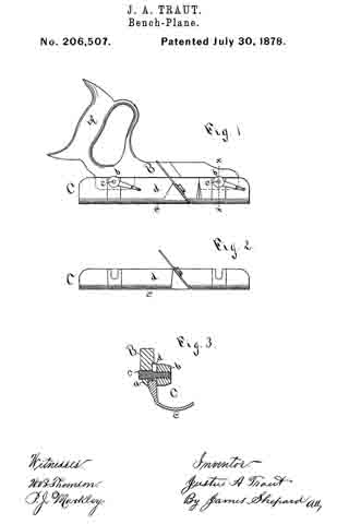
Be it known that I, D. MILTON HEALD, of Milford, county of Hillsborough, State of New Hampshire, have invented an Improvement in Planes, of which the following is a specification:

This invention relates to improvements in planes, and has reference more especially to the method and means of supporting and adjusting the plane-iron in the throat, the invention being applicable to both wood and metal planes.

The cap, connected, as usual, with the plane-iron, is provided with a recess to receive the end of a cap-screw carried by a slide made adjustable by means of an adjusting-screw in guideways of a plate, f, pivoted within the body of the plane, so that as the slide is moved by the adjusting-screw the plane-iron and cap are moved longitudinally in the throat.

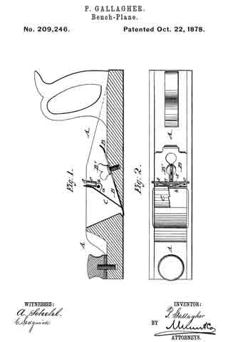
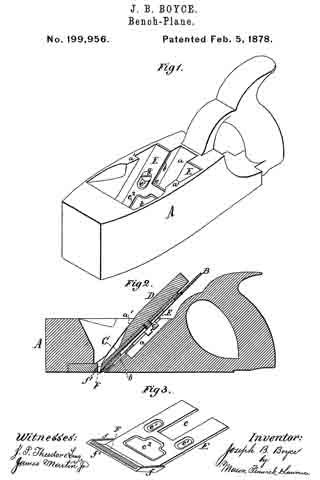
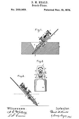
Figure 1 represents, in longitudinal vertical section, a plane provided with my improvements; Fig. 2, a front-end view thereof. Fig. 3 represents a modidcation hereinafter referred to.

As shown in this instance of my invention, the body a of the plane is supposed to be of wood and to be provided with a throat, b, extended therethrough in the usual manner.
The plane-iron c and its cap d are adjustably connected by means of the screw e, as in other planes.

The plane-iron holder f, preferably made of cast metal and pivoted to the body of the plane at g, has formed in it a guide slot or way, h, to receive a slide, i, which is made longitudinally adjustable therein by means of an adjusting-screw, j, preferably a compound screw, as shown in Figs. 1 and 2, it being composed of a coarse-threaded portion, k, fiitted to a lug, l, of the iron holder f, and of a finer-threaded portion, m, fitted to a lug, n, of the slide i. This slide i is provided with a cap-screw, o, having at its end a tenon, p, which enters a recess in the cap d, there being a shoulder on the screw a short distance per face of the cap and hold it and the plane-iron down in contact with the portion q of the body of the plane within the throat.

When the screw o is turned so that the tenon p enters the recess in the cap, it is obvious if the compound screw be turned that it will act upon the slide i and move it in the slot of the holder f and move with it the plane-iron and cap to regulate the degree of their projection below the face of the plane.

It is obvious that the end of screw o might be recessed to receive a tenon projecting from the cap.

By providing the screw j with threads of different pitch its power is increased. Such screw takes the place of the lever or cam commonly used in other adjustable planes.

The compound screw and cap-screw being located above the iron enables it to be more readily adjusted than can be the irons of other planes wherein the adjusting devices are below the iron.

The screw j might be provided with a thread of uniform pitch; but threads of two pitches are preferable. This compound screw is lntended to operate on the principle of the well-known “Hunter screw.”

I claim —

The combination, with the plane-body, of an iron-holder, f, pivoted thereto, a slide fitted to the said iron-holder, an adjusting-screw to move the slide longitudinally in the holder, and a cap-screw, o, carried by the slide, the said cap-screw being adapted to engage the cap d, located below the holder, to thereby adjust it and its attached plane-iron in unison, substantially as described.

In testimony whereof I have signed my name to this specification in the presence of two subscribing witnesses.

DANIEL MILTON HEALD.

Witnesses:
JOHN M. STANYEM,
LEONARD W. FRENCH.

No. 209,246 – Improvement In Bench Planes (Patrick Gallagher) (1878)

[paiddownloads id=”295″]209246


UNITED STATES PATENT OFFICE.

_________________

PATRICK GALLAGHER, OF EUREKA, NEVADA.

IMPROVEMENT IN BENCH-PLANES.

_________________

Specification forming part of Letters Patent No. 209,246, dated October 22, 1878; application filed August 29, 1878.

_________________

To all whom it may concern:

Be it known that I, PATRICK GALLAGHER, of Eureka, in the county of Eureka and State of Nevada, have invented a new and Improved Bench-Plane, of which the following is a specification:

In the accompanying drawings, Figure 1 represents a vertical longitudinal section of my improved bench-plane, and Fig. 2 is a top view of the same with a part broken off.

Similar letters of reference indicate corresponding parts.

This invention has reference to improvements in bench planes, so that the cutting-iron lies flat and will make a smoother cut in the wood, being also more easily adjusted than in the old styles of planes, in which the iron is retained by a wedge-piece.

The invention consists of a bench-plane whose cutter is firmly retained by a clamp-screw and a hinged and spring-acted cover on the slanting seat of the plane.

Referring to the drawings, A represents a bench-plane, either a jack-plane, fore-plane, or jointer, and made of wood or iron, of the usual size and shape. The iron cutter B is secured by a clamp-screw and slot to the slanting bottom of the plane, which is laid flat thereon, so as to cut smoother. It is held firmly in position near the cutting-edge by a metallic cover or cap, C, that is hung by ears a to a cross-pin, b, the part above the pin being set at an obtuse angle to the lower part, and acted upon by strong band-springs d, that are riveted to a detachable piece or bridge, e, secured to side grooves of the plane. The springs d press the lower end of the cover or cap C firmly on the cutter and secure it in position, while admitting its more convenient adjustment than when fastened by a wedge, as in the planes in general use. The cutter may be turned over, if desired, so that the bevel of the cutting-edge will be either up or down, according to the grain of the wood to be planed. For changing or removing the cutter the clamp-screw has to be unscrewed and placed in line with the slot, when, by pressing on the upper part of the cover, the iron can be readily taken out. When replacing it the clamp-screw is tightened and the cutter thereby held rigidly in connection with the spring-cap.

Having thus fully described my invention, I claim as new and desire to secure by Letters Patent —

In a bench-plane, the combination of a cutting-iron, screwed to the plane by a clamp-screw, with a hinged cap or cover, and with springs attached to a detachable cross-piece or bridge, substantially as and for the purpose specified.

PATRICK GALLAGHER.

Witnesses:
H. A. KNIGHT,
JAMES G. FORD.

No. 207,599 – Improvement In Bench-Planes (Henry A. Foss) (1878)

[paiddownloads id=”294″]207599


UNITED STATES PATENT OFFICE.

_________________

HENRY A. FOSS, OF PINE MEADOW, CONNECTICUT, ASSIGNOR TO PHILIP E. CHAPIN, OF SAME PLACE.

IMPROVEMENT IN BENCH-PLANES.

_________________

Specification forming part of Letters Patent No. 207,599, dated September 3, 1878; application filed April 15, 1878.

_________________

To all whom it may concern:

Be it known that I, HENRY A. FOSS, of Pine Meadow, in the county of Litchfield and State of Connecticut, have invented certain new and useful Improvements pertaining to a Carpenter’s Plane, of which the following is a specification, reference being had to the accompanying drawings, where —

Figure 1 is a top view of a plane embodying my improvements. Fig. 2 is a side view of same. Fig. 3 is a bottom view of the fastening-lever. Fig. 4 is a view of the fastening-lever in central longitudinal section. Fig. 5 is a side view of the lower end of the fastening-lever.

The letter a denotes the body or stock of a metallic plane. b denotes the plane-iron, which may or may not be supplemented by a cap-iron lying on a proper bed and running down to the throat. The letter c denotes the fastening-lever, bearing on its sides the fulcrum-ears d d, resting in the fulcrum-mortises e e, which are made in the plane-stock, provided near the upper end with the tightening-screw f and at the lower end with the rocking end g, which is pivoted to the fastening-lever in such shape as to allow it to rock and adjust itself to bear squarely and flatly on the plane-iron. To secure this rocking motion, the lower end of the fastening-lever is provided with the pivot-pin h, which runs through a corresponding pin-hole, i, in the rocking end, and is provided with a head on the under side. Preferably the spring j is also secured on this pin, bearing against the under side of the rocking end.

The sides of the plane-body are provided with or shaped into the swells k k, and the fulcrum-mortises e e are made just underneath these swells. These swells allow the passage of the fulcrurn-ears d d down to the fulcrum-mortises. Then, by sliding the fastening-lever slightly forward, the ears d d are carried to the forward ends of the mortises, which are inwardly shouldered, so that the ears lock under at this point. This construction not only allows the fulcrum-mortises to be cast, but the swells give a good gripe for the hand of the operator.

The letter l denotes a knob or handle, fastened to the fastening-lever c by having the screw l’ cast in or projecting from the fastening-lever, and running into the knob. Another mode of fastening on this or such a knob is illustrated by the knob m, which is driven into the ring m’, cast on or projecting from the floor of the plane-stock.

I claim as my invention —

1. In combination with the plane-body and plane-iron, the fastening-lever c, provided with the rocking end g, substantially as described, and for the purpose set forth.

2. The fastening-lever c, provided with the screw l’, and combined with the knob l.

HENRY A. FOSS.

Witnesses:
JAMES WILEY,
O. T. HUNGERFORD.

No. 206,507 – Improvement In Bench-Planes (Justus A. Traut) (1878)

[paiddownloads id=”293″]206507


UNITED STATES PATENT OFFICE.

_________________

JUSTUS A. TRAUT, OF NEW BRITAIN, CONNECTICUT.

IMPROVEMENT IN BENCH-PLANES.

_________________

Specification forming part of Letters Patent No. 206,507, dated July 30, 1878; application filed June 3, 1878.

_________________

To all whom it may concern:

Be it known that I, JUSTUS A. TRAUT, of New Britain, in the county of Hartford and State of Connecticut, have invented certain new and useful Improvements in Planes, of which the following is a specification:

The invention relates to that class of small planes known as “rounds,” “hollows,” “beading-planes,” &c.; and the invention has for its object the production of this class of planes in iron, whereby they are more durable and as cheap or cheaper than wooden ones, and also to make one or two handles and frames answer for many stocks or for a complete set, whereby they are less expensive and occupy less space for storage than those heretofore made.

My invention consists, first, of a plane handle and frame, having a longitudinal rabbet and provided with clamping mechanism, in combination with a separately-formed plane-stock and its cutter, adapted when united to be readily attached and detached to the side of said frame, as hereinafter described; and, second, in the particular clamping mechanism, as hereinafter described.

In the accompanying drawing, Figure 1 is a side elevation of a plane which embodies my invention. Fig. 2 is a side elevation of the plane-stock detached; and Fig. 3 is a vertical section on line x x of Fig. 1.

A designates the handle, and B its frame, the latter having two depending lugs, a. (Indicated by broken lines in Fig. 1, and one of which is shown in Fig. 3.) These lugs are off-set a little from the body of the frame, so as to form a longitudinal rabbet to receive the stock C.

b b designate lever-nuts on the ends of screws c, which pass through the lugs a. These screws are made with a coarse thread on one end and a fine thread on the largest end, which is screwed into the lugs, the same fitting snugly, so as not to be easily rotated therein.

The bed e of the stock C may be of any desired form for any of the ordinary small planes — as, for instance, the round-bottom, as shown in Figs. 1 and 3, or the hollowing bottom.
(Shown in Fig. 2.) The stock in each case will have its own cutting-iron attached thereto by any suitable means, so as to be united when detached from the frame, and also an upward-projecting flange, d, the same being slotted at proper points to receive the body of the screws c c, and preferably thickened a little by the sides of said slot, so that they may easily be dressed to a uniform thickness in all of the different stocks.

The upward-projecting flange d of the stock c extends from one side of the bed e, as shown most clearly in Fig. 3. whereby the stock, although of metal, may be made light, and also with ample room over the bed for the lever-nuts to work in and not have them interfere with the working of the plane.

When the stock is placed in the rabbet of the frame and the lever-nuts tightened, as shown in Fig. 1, the device is ready for use. When a different stock is wanted, the lever-nuts are thrown backward, the stock removed, and another substituted therefor by placing the flange d in the rabbet of the frame, the body of the screws meantime being received in the slots of the flange. The lever-nuts are then thrown forward to firmly bind the stock to the frame of the handle. The end of the screws which receives the nuts is made small, in order that it may be passed through the lugs a from the opposite side and not interfere with the finer thread in said lugs. The thread for the lever-nuts is made coarse, in order that only a partial turn may be necessary in order to tighten the stock in the frame, while the lever-nuts are made long enough to compensate for the loss of power consequent upon the use of the coarse thread. In case the lever-nuts do not stop in the right position when holding the stock, the position of the screw may be changed by means of a screw-driver inserted in the slotted end of the screws until they are adjusted to bring the lever-nuts home in the proper place, as shown in Fig. 1.

By fitting the fine thread snugly in the lugs and the coarse thread of a smaller diameter loosely in the nuts, the action of said nuts will not change the position ofthe screws.

By making a longitudinal rabbet in the frame and clamping one side of the stock at one of its upper corners to the side of said frame, the opposite side of the stock is wholly free from all projections, even in stocks of variable widths, (see Fig. 3,) whereby they may be worked flush up against a deep shoulder, as it is often desirable to do in this class of planes.

I am aware that planes have been made with detachable handles, connected by clamping mechanism to the rear upper corner of the plane-stock; also, that plane-stocks have been divided longitudinally in a horizontal plane, so that different-shaped bottoms and different cutting-irons could be used in connection with the common handle and top part of the stock, all of which prior devices are hereby disclaimed.

I claim as my invention —

1. The plane handle and frame having a longitudinal rabbet and provided with clamping mechanism, in combination with a separately-formed plane-stock and its cutting-iron, adapted, when united, to be readily attached and detached to and from the side of said frame, substantially as described, and for the purpose specified.

2. The frame B, having screws c c, with fine and coarse threads, in combination with the lever-nuts b b and the slotted flange of a plane-stock, substantially as described, and for the purpose specified.

JUSTUS A. TRAUT.

Witnesses:
JAMES SHEPARD,
WILL. B. THOMSON.

No. 203,442 – Improvement In Bench-Planes (Robert S. Griffin) (1878)

[paiddownloads id=”292″]203442


UNITED STATES PATENT OFFICE.

_________________

ROBERT S. GRIFFIN , OF WORCESTER, MASSACHUSETTS.

IMPROVEMENT IN BENCH-PLANES.

_________________

Specification forming part of Letters Patent No. 203,442, dated May 7, 1878; application filed April 6, 1878.

_________________

To all whom it may concern:

Be it known that I, ROBERT S. GRIFFIN, of Worcester, in the county of Worcester and State of Massachusetts, have invented a new and valuable Improvement in Planes; and I do hereby declare that the following is a full, clear, and exact description of the construction and operation of the same, reference being had to the annexed drawings, making a part of this specification, and to the letters and figures of reference marked thereon.

Figure 1 of the drawings is a representation of a plan view of the plane-stock, with the bit and cap removed, showing the back plate and its attachments. Fig. 2 is a longitudinal vertical section of the plane, and Fig. 3 is a perspective view of the bottom of the bit or blade.

This invention has relation to improvements in planes.

The object of the invention is to devise a means whereby the blade may be adjusted to cut shavings of various thicknesses, and secured to the stock without the employment of wedges or other like devices.

The nature of the invention consists in combining with the back plate aforesaid, having the projecting-screw, the longitudinally-slotted bit, the cap, and the thumb-nut, an adjusting-screw having a screw-seat upon the under side of the said back plate, and engaging a forked offset on the back of the plane-bit, whereby, the thumb-nut being loosened, I am able to adjust the bit to cut a fine or coarse shaving, as will be hereinafter more fully set forth.

In the annexed drawings, the letter A designates the plane-stock, having the usual flaring recess a and throat a’. B represents a metallic back plate, recessed into the rear inclined wall of the recess a. so as to be flush therewith, and provided, near its lower edge, with a projecting screw, B’. This screw is at right angles to the plane of the said back plate. C represents an adjusting-screw, having its bearings in a female-threaded offset, b, near the top, and on the under side of the back plate, and provided, near its upper end, with an annular grove, c, the functions of which will be hereinafter set forth. The screw C has at its upper end a head, d, by which it is conveniently manipulated, and it works in a groove, e, in the rear inclined wall ofthe recess a. D indicates the planing-bit, having a longitudinal slot, f, through which the screw B’ extends, and near its upper end a forked offset, g, that straddles the adjusting-screw in the groove c aforesaid, snugly. By operating the screw C, the planing-bit is raised or lowered to any desired extent. J indicates the cap, having an oblong slot, h, in its median line, through which the screw B projects. The cap and planing-bit are forcibly clamped against the stock, or rather the end wall of the recess a, by a thumb-nut, L, or its equivalent, applied upon the end of the screw B’. This nut being loosened, the bit may be adjusted to cut a thin shaving or a thick one, as may be required, by operating the adjusting-screw C, to raise or lower the planing-bit. The cap, being also slotted, may be also adjusted in conformity with the adjustment of the bit.

It will be seen that by means of the back plate, its projecting screw, and the thumb-nut above described, the planing-bit and cap are adjusted according to requirements, without the employment of wedges or other equivalent devices, and that the said devices may be raised or lowered, as the case may be, by simply loosening the thumb-nut and actuating the adjusting-screw. This latter is connected to the planing-bit by the engagement of the forked onset with the annular groove aforesaid.

What I claim as new, and desire to secure by Letters Patent, is —

The combination of the plane-stock A, having groove e in its rear wall, the back plate B, carrying screw B’, and the screw-threaded offset b, and the adjusting-screw C, having annular groove c, and working in said offset, with the longitudinally-slotted bit D, having forked offset g upon its under side, near its upper end, the slotted cap J, and thumb-nut L, substantially as specified.

In testimony that I claim the above I have hereunto subscribed my name in the presence of two witnesses.

ROBERT S. GRIFFIN.

Witnesses:
ERVING F. RICE,
T. H. HAZFORD.

No. 202,918 – Improvement In Carpenters’ Planes (Leonard Bailey) (1878)

[paiddownloads id=”291″]202918


UNITED STATES PATENT OFFICE.

_________________

LEONARD BAILEY, OF HARTFORD, CONNECTICUT.

IMPROVEMENT IN CARPENTERS’ PLANES.

_________________

Specification forming part of Letters Patent No. 202,918, dated April 30, 1878; application filed February 20, 1878.

_________________

To all whom it may concern:

Be it known that I, LEONARD BAILEY, of Hartford, in the county of Hartford and State of Connecticut, have made certain new and useful Improvements pertaining to Carpenters’ Planes, of which the following is a specification, reference being had to the accompanying drawings, where —

Figure 1 is a side view of the plane. Fig. 2 is a central longitudinal section of the plane. Fig. 3 is a detail view of a modification hereinafter described.

The invention is a new adjustment for plane bits or irons, particularly adapted to metallic planes.

The letter a denotes a stud borne and having longitudinal play in a corresponding socket in the riser b. Its lower end bears a male screw-thread meshing into the round nut c, which lies in the socket d in the riser b. It is by the rotation of this nut by the hand or fingers of the operator that the stud-pin a is advanced or retracted. The top of this stud bears, when advanced, against the under side of the bit or iron e, thus availing to fasten it in place. When this stud-pin is retracted its hold on the bit is loosened. This stud-pin bears near the top a screw-pin, f, furnished with an operating-handle, g. When this pin f runs through the stud a its thread is right-handed, denoted by the letter h. Below this right-hand thread the pin is furnished with a left-hand thread, and this left-hand thread bears the button j, and this button bears the stud or pin k, entering one or the other of the series of holes l in the plane-bit.

This use of a right and left hand thread enables me to adjust the plane-bit with great rapidity and small movement, and is available for this purpose, whether it be hung in the stud a, or run through a rigid projection from the plane-body.

This use of a right and left hand thread also enables me to make the screw work in the stud without pinning it in or placing collars on the screw-shaft each side of the stud. This is not only an advantage in making, but also in using, the screw-shaft being removable without taking out such a pin or taking off such collars.

The pin f may, in some cases, have but a single thread, and in such case the button j is made stationary on the pin, but in such manner that the pin can turn in the button. This can be attained by the modification shown in fig. 3.

There is a feature of novelty connected with the handle g. This handle is hinged or pivoted to the end of the screw f. Ordinarily it stands out like a crank-arm, as shown in the drawings, and forms a ready means of rotating the screw f; but it has a peculiar advantage when a screw or other rotating shaft is employed in a plane adjustment and in a relation similar to that herein described.

When the plane-bit is adjusted high up in the plane, so that its upper end covers the joint or hinge between the screw and this handle, obviously this handle cannot have a complete rotation while standing out at any considerable angle from the screw. In such case the handle is rotated crank fashion till it comes up against the bit. It is then swung over on its pivot to the opposite side of the screw, when its rotation crank fashion can be continued.

I am aware that to accomplish the adjustment of a plane-bit within contracted limits a differential screw has been used, such screw consisting of a hollow or tubular thumb-screw, threaded both interiorly and exteriorly, and engaging a screw carrying the bit-connection. My screw differs from this, in so far as it is differential, in that it is a double-threaded screw of one piece, one of its threaded portions working within the bearing that supports the screw, and the other entering and working within a nut carrying the plane-bit.

I claim as my invention —

1. The double-threaded adjusting-screw f, made in one piece, and having a right-hand thread working in its support or bearing and a left-hand thread working in the bit-carrying nut, in combination with a plane body and bit, substantially as described.

2. In combination, stud a, nut c, adjusting-screw f, button j, bearing-pin k, and the plane-bit, all substantially as described.

3. The combination of the plane-bit, the button j, the stud a, and the rotating shaft f, provided with the pivoted handle g.

LEONARD BAILEY.

Witnesses:
ROBT. F. GAYLORD,
WM. E. SIMONDS.

No. 202,674 – Improvement In Bench-Planes (Charlotte Smith) (1878)

[paiddownloads id=”290″]202674


UNITED STATES PATENT OFFICE.

_________________

CHARLOTTE SMITH, OF CHELSEA, MASSACHUSETTS, ADMINISTRATRIX OF JOHN F. SMITH, DECEASED.

IMPROVEMENT IN BENCH-PLANES.

_________________

Specification forming part of Letters Patent No. 202,674, dated April 23, 1878; application filed March 26, 1878.

_________________

To all whom it may concern:

Be it known that I, CHARLOTTE SMITH, of Chelsea, Suffolk, State of Massachusetts, administratrix of the estate of my deceased husband, JOHN FRANCIS SMITH, of said city, county, and State, do declare that the said deceased, during his lifetime, did invent a new and useful Plane-Iron Cap, of which the following is a specification:

The nature of the invention is that of a plate of metal of peculiar form, detachable, but when in use fastened by a peculiar device to one side of a plane-iron, being an improvement on the well-known plane-iron top of a carpenter’s plane; and the object of the improvement is to effect the ready removal of the top when required, and also the firmer holding it in place when in use.

Figure 1 is a view of one side of the plane-iron, showing the nut used to fasten the top, and the necessary slot in the plane-iron, &c. Fig. 2 is a vertical cross-section, giving the relative positions of the plane-iron, the top with its screw, and the nut of the same.

In the drawings, A, Figs. 1 and 2, is the plane-iron or blade of a carpenter’s plane. B, Fig. 1, is a slot in the same, of any convenient length or width, running lengthwise of the plane-iron. C, Figs. 1 and 2, is a nut, with a projection each side of it, (seen in Fig. 1,) forming a thumb-screw, a, being worked by the thumb and finger, screwed onto the screw D, Figs. 1 and 2, which screw passes through the slot B, Fig. 1, as seen in Fig. 2, and at the right-hand side in Fig. 2 is attached to the plane-iron top E, Fig. 2. A shoulder (seen in both figures, in dashed lines in Fig. 2) is attached to the base of the screw D, and also to the top E, and is cut away (see Fig. 1) on each side of the screw D, so as to enter into the slot B.

The inner surface of the top E is seen in Fig. 2 not to lie flat on the plane-iron, but to rest on the same by its ends, which are both, in the same figure, seen to be curved. The thinness of the top E, with the two curves noted, makes of it a spring of greater or less strength, as the thickness of the top E may vary.

It is not proposed to confine ourselves to any particular thickness of the top, nor to any particular curve of the ends. A circular enlargement is sometimes made of the slot B near one or the other end; but this is not claimed here as original.

The length of the shoulder portion left on entering into the slot B may be varied. The whole device of the top and its attachment may be adapted to any plane-iron, the size of the thumb-screw being varied to suit the width of th slot which may be borne by the plane-iron.

Operation: The parts of the device being in place, as seen in the drawings, the nut C is turned by the thumb and finger, thus bending, more or less, the top E and pressing the curved ends more tightly on the plane-iron. When the top E is to be removed there is no loss of time in searching for a screw-driver; but the thumb-screw C is readily turned by the thumb and finger, as before, and the top E is at once loosened; and if the slot B is cut as drawn in Fig. 1, the thumb-screw C is removed, when the top E is readily removed to admit the sharpening of the cutting-edge of the plane-iron.

If the circular enlargement referred to as optionally provided is present, the nut need not be removed, the thumb-screw arms in that case passing through the slot B.

I do not claim the providing the top with a single curved end.

I claim for the inventor —

1. The double curved plane-iron top shown, in combination with the plane-iron, the shoulder, the screw D, and a nut, all when constructed and fitted for use, substantially as described and shown.

2. The combination of the thumb-screw with its arms, the screw D, the shoulder seen, a plane-iron, and a plane-iron top, all when constructed and arranged substantially as described and shown.

CHARLOTTE SMITH,
Admimistratrar of John Francis Smith.

Witnesses:
JOS. B. BELL,
LEMUEL P. JENKS.

No. 201,068 – Improvement In Bench-Planes (Harrison P. Taylor) (1878)

[paiddownloads id=”289″]201068


UNITED STATES PATENT OFFICE.

_________________

HARRISON P. TAYLOR, OF MINERVA, OHIO.

IMPROVEMENT IN BENCH-PLANES.

_________________

Specification forming part of Letters Patent No. 201,068, dated March 5, 1878; application filed September 7, 1877.

_________________

To all whom it may concern:

Be it known that I, HARRISON P. TAYLOR, of Minerva, in the county of Stark and State of Ohio, have invented certain new and useful Improvements in Bench-Planes; and I do hereby declare that the following is a full, clear, and enact description thereof, which will enable others skilled in the art to which it appertains to make and use the same, reference being had to the accompanying drawings, which form a part of this specification, and in which —

Figure 1 is a perspective view of a plane with my improved plane-guide attached to the side. Fig. 2 is a similar view, showing the guide-strip attached to the face of plane. Fig. 3 is a side elevation of the guide detached. Fig. 4. is an edge view of the same, and Fig. 5 is an end view.

Similar letters of reference indicate corresponding parts in all the figures.

My invention relates to guides for edge-planing; and consists in the construction of a reversible guide, which may be used either on the side or on the face of the plane, as circumstances shall render desirable, substantially as I shall now proceed more fully to describe, my present invention being an improvement on the invention for which Letters Patent of the United States No. 165,132 were granted to me on the 29th day of June, 1875.

In the drawings, A represents the plane, which may be of any suitable size and construction. The guide consists of a beveled strip of wood or metal, B, upon the beveled side or face of which is secured a metal plate, G, having turned-over parallel side flanges c c, by which a dovetailed slot or groove, b, is formed. In this groove slides a dovetailed plate, D, carrying a set-screw, d, by means of which it may be adjusted in any given position in relation to plate C. Secured at right angles upon plate C is a segment, E, which has a segmental slot, e, and the front edge of which is marked with a graduated scale. (See Fig. 4.)

F is the key-plate, which has a key-hole-shaped slot or mortise, f and is secured to the end of a slotted arm, G G’, pivoted at g to the point or center of the segment E, arms G G’ corresponding, therefore, to the radius of a circle whose center is at g, so that they will move freely on both sides of the slotted segment E. Through slot e passes a set or clamp screw, h, which unites arms G and G’, and by turning which these may be made to clamp the segment firmly, so as to remain immovably in position.

From the foregoing description, taken in connection with the two sheets of drawings, the manner of using my plane-guide will be readily understood. For ordinary use, it is secured upon the side of the plane, as shown in Fig. 1, so that only the narrow edge a of the guide-strip B shall bear against the face of the plane. To apply it to the plane, the bolt x is loosened a little, the large opening in the key-plate F is slipped over the bolt-head, after which the plate is pushed up against the bolt so as to bring the shank into the lower narrow part of the hole or mortise, when the bolt is again tightened, and the guide is in position ready for use. The angle of strip B is then regulated (according to the angle the edge is to have) by means of the clamp G G’, clamp-screw h, and the slotted and graded segment E, while vertical adjustment — that is, the distance between the bolt x upon which the guide is secured and the upper edge of the guide-strip — may be adjusted by means of the sliding plate D and set-screw d, so that my guide may be used on planes having different heights or distances between their side bolts and faces by a simple and easily effected adjustment of the guide.

If the plane-bit is dull in one place, or at one edge or side, the guide-strip B may be reversed, without detaching the adjusting mechanism from the plane, by simply loosening set-screw d, sliding plate C off of plate D, reversing the strip and plate, and sliding it on again from the opposite (thick) side of the strip, after which it is again secured in place by the set-screw d. When in this position (represented in Fig. 2) the strip will project over the face of the plane a width of about an inch, and covering the dulled part of the bit, so that full use may be had of its remaining exposed edge.

The manner of angular and vertical adjustment is, of course, precisely the same as that already described in explaining the adjustment of the guide when used as represented in Fig. 1.

This guide, consisting as it does, of few parts, is simple and durable in construction, will fit any plane, and can be produced at a small cost. It cannot give or spring while in use, but insures a true edge without any deviation from the proper angle, according to the set or adjustment of the guide at starting,

Having thus described my invention, I claim and desire to secure by Letters Patent of the United States —

l. The beveled guide-strip B, having grooved plate C, in combination with the reversible plate D and vertically-adjustable key-plate F, substantially as and for the purpose herein shown and specified.

2. The combination of the slotted, and vertically-adjustable key-plate F with the graduated segment E, provided with the reversible plate D, substantially as and for the purpose herein shown and described.

3 The combination of the reversible plate D, provided with the slotted and graduated segment E, with the beveled or wedge-shaped guide-strip B, substantially as and for the purpose herein shown and specified.

In testimony that I claim the foregoing as my own I have hereto affixed my signature in presence of two witnesses.

HARRISON P. TAYLOR.

Witnesses:
GEO. KRYDER,
JOHN L. GOWER.

No. 199,956 – Improvement In Bench-Planes (Joseph B. Boyce) (1878)

[paiddownloads id=”288″]199956


UNITED STATES PATENT OFFICE.

_________________

JOSEPH B. BOYCE, OF LOCKPORT, NEW YORK.

IMPROVEMENT IN BENCH-PLANES.

_________________

Specification forming part of Letters Patent No. 199,956, dated February 5, 1878; application filed January 12, 1878.

_________________

To all whom it may concern:

Be it known that I, JOSEPH B. BOYCE, of Lockport, in the county of Niagara and State of New York, have invented a new and useful Improvement in Bench-Planes, which improvement is fully set forth in the following specification and accompanying drawings, in which latter —

Figure 1 is a perspective view of a common bench-plane provided with my improvement, the bits and wedge being removed in order to exhibit the improvement more fully. Fig. 2 is a vertical central longitudinal section through the plane in working condition. Fig. 3 is a perspective view of that part of the plane which I have improved.

The nature of my invention consists in certain construcinons, combinations, and arrangements of parts, hereinafter described and specifically claimed, whereby an improved adjustable metal lining for the throat and mouth of a bench-plane is produced.

The object of my invention is to protect the parts of a plane most exposed to wear by a metal lining which is of simpler construction than heretofore made, so that its application to a plane will not necessitate any material change in the construction of the plane to which it may be applied, and which may be as easily applied to an old as to a new plane.

In the drawings, A represents the body of an ordinary plane; B, the plane-iron; C, the cap-iron, with the usual coupling set-screw c and wedge D. The bed b of the plane is provided with a metal plate, E, which has an open slot, e, two oblong countersunk slots, e1, a central opening, e2, and an oblong mouth, F, which mouth F consists of abutting sides or shoulders f and a transverse connecting-strip, f’.

The plate E may be inserted from the face of the plane after the bed b of the plane has, if needs be, been reduced to receive it, and the wood at the sides and front of the mouth of the plane suitably mortised away, in order to receive the shoulders f and connectionf’, and thus the shoulders f serve as abutments for preventing the upward movement of the plate E by violent strains on the plane-iron. The plate E is fastened to the bed b of the plane by means of set-screws g, and, by means of these screws and the slots e1 e1, the readjustment of the plane-face may also be effected.

Upon the plate E the plane-iron B, with its cap C, coupled to it by the screw c, is placed, and its screw c allowed to pass into the usual recess a, which is in rear of the oblong opening e of the plate E, and, thus applied, the plane-iron and its cap are fastened with the wedge D.

The plane A is, by this construction, in a ready manner, and without material change of its throat, and at slight cost, provided with a very substantial protection of its bed and other parts liable to injury from wear.

It will be seen that while the center part of the plate E is cut away at e to admit of the passage of the large head of the set-screw c, in the usual manner, down the recess a, and at the opening e2, in order to lessen cost, still there is a continuous metal surface at either side, just opposite the wedge-abutments a’, which affords a firm bearing of the plate E upon the bed b of the plane. The plate E, above its shoulders f f is as wide as the throat or the bed of the plane, and the distance between the inner sides of the shoulders f is the same as the width of the plate E; consequently the width of the throat need not be increased in order to provide a plane with a plate, E. Besides this, any plane, new or old, may be so provided and improved without weakening the plane, by simply mortising from below, to admit the shoulders f f and connecting-strip f’. The lower end of the plate E, in conjunction with the parts f and f’, forms a lining for the mouth of the plane, and constitutes a part of the plane around its mouth, thereby protecting the plane against premature wear in and around the mouth.

I would state that the plate E may be solid at e2 without departing from my invention.

Having described my invention, what I claim as new, and desire to secure by Letters Patent, is —

1. In combination with the body and plane-iron of a carpenter’s plane, the lining-plate E, having slots e1 e1 and a longitudinal opening, e, and a mouth, F, formed with abutting shoulders f united as at f’, substantially as and for the purpose set forth.

2. A metal lining-plate, E, for a carpenter’s plane, the lower portions of which are constructed as at f, f’, and F, and the upper portion provided with a central longitudinal opening or slot, e, to correspond or register with the groove a of an ordinary plane, substantially as and for the purpose described.

Witness my hand, in the matter of my application for a patent for a bench-plane, this 8th day of January, A. D. 1878.

JOSEPH BENSON BOYCE.

Witnesses:
T. D. BABCOCK,
JAS. A. NEWTON.

No. 216,979 – Improvement In Bench Planes (Jacob Siegley) (1878)

[paiddownloads id=”60″]216979


UNITED STATES PATENT OFFICE.

_________________

JACOB SIEGLEY, OF NEW YORK, N. Y.

IMPROVEMENT IN BENCH-PLANES.

_________________

Specification forming part of Letters Patent No. 216,979, dated July 1, 1879; application filed December 6, 1878.

_________________

To all whom it may concern:

Be it known that I, JACOB SIEGLEY, of the city, county, and State of New York, have invented certain new and useful Improvements in Conibination Bench-Planes, of which the following is a specification, reference being had to the acompanying drawings, in which —

Figure 1 represents a side view of my improved bench-plane arranged as a plow. Fig. 2 is a side view of the gage or fence used therewith. Figs. 3, 4, and 5 are, respectively, a side view, top view, and vertical transverse section on line x x, Fig. 3, of the bead-plane to be used in connection with the stock of the bench-plane. Figs. 6 and 7 are a side view and a cross-section on line y y, Fig. 6, of a scratch-bead plane. Figs. 8, 9, and 11 are, respectively, a side view, top view, and vertical transverse section on line z z, Fig. 9, of the “dado” or rabbeting attachment ; and Figs. 10 and 12 are vertical transverse sections on lines c c and k k of the plane arranged as a plow or grooving-plane.

Similar letters of reference indicate corresponding parts.

This invention refers to such improvements in the bench-plane for carpenters’ use that the same may be used with greater facility either as a plow, bead-plane, scratch-bead, or dado or rabbeting plane for the different purposes of grooving, beading, and rabbeting, the parts of the plane and interchangeable attachments being so constructed as to take up much less room in the tool-chest than the common wooden planes in use. The different parts are also quickly adjusted on the main stock, and the work accomplished in a more perfect and accurate manner without any sandpapering or finishing of the edges.

The various attachments to the plane answer to all requirements of the work, and are, by the simpler, stronger, and more compendious shape, more convenient in use and less expensive than the diiferent sizes of wooden planes at present employed.

The invention consists of a main stock having a laterally adjustable and detachable side gage or fence, a vertically-adjustable double stop-gage, and interchangeable advance or lead cutters.

To eye-slots of the blade of the stock are locked the diiferent sizes of bead-planes, scratch-beads, and the dado or rabbeting plane, which are all provided with advance cutters for preventing the tearing of the edges by the cutters.

The dado is laterally adjustable to different sizes, and may, as well as the scratch-beads, be used in connection with the side gage and double-stop gages of the stock.

Referring to the drawings, A represents the stock of my improved bench-plane, which is made of iron or other suitable metal, with the customary handle and inclined bearing-surface for the detachable plow or grooving-iron B. The latter is secured to its bearing-surface by a pivot, lever, and clamp-screw, (shown in Fig. 1,) as commonly used in iron planes. Into the grooved bottom part of the stock is firmly secured the blade C, which extends throughout the whole length of the stock, and is recessed in suitable manner for the plow and other parts.

The blade C is provided with two or more eye-slots, a, which serve for admitting the beads of the locking-studs a’ of the bead-planes, scratch-beads, rabbeting-planes, and other attachments to be used in connection with the plow-stock A.

At one side of the stock extend horizontal guide-posts D, which are permanently secured to the stock, for the laterally-adjustable side gage or fence, E. This gage or fence E is hung by arms b, with horizontal sleeves b1, to the posts D, and readily adjusted thereon to any distance from the stock, and then secured by set-screws d, as shown in Figs. 2 and 12. This side gage serves to guide the plow, bead, or rabbeting plane at the required distance from the edge, in the well-known manner in bench-planes.

The stock A is next arranged in front of the plow, with a double stop-gage, F, whose shank F’ is vertically guided in recesses e of the stock and blade, and adjusted to any distance from the lower edge of the blade by a screw-nut, e1, working on the threaded bolt end of the shank F’. The rigid position of the double stop-gage F is secured by a side set-screw, e2, which prevents the gage from slipping while in use. The stop-gage extends at both sides of the stock-blade, and furnishes thereby a steadier and more reliable gage than the single stop heretofore in use at one side of the stock. The stop-gage is grooved at the under side, the groove extending centrally through its entire length, so as to enable the adjustment of the stop-gage to a point below the recess of the blade.

By this quickly-adjustable and positively-secured stop-gage the work is accomplished in a more reliable and accurate manner, and, owing to the rigid hold in the body of the stock, any possibility of irregular work prevented.

The blade has a vertical recess in front of the stop-gage F for the advance cutters G, which are shown in Figs. 1 and 10. These advance cutters are secured by means of a clamping-screw, f and the movable front portion, C’, of the blade C, the advance cutters being made of different sizes, corresponding to the different sizes of plows, so that each size of plow works with its corresponding size of advance cutter. The movable blade-section C’ is guided by slots on cross-pins ofthe stock, and firmly locked to the cutter G by the clamp-screw f The advance cutters do away with the work of running a gage over the board, and prevent the plows from tearing the edges in cross-grain timber. This is an important time and labor saving attachment, as it produces smoother edges and dispenses with the sandpapering or otherwise finishing of the same.

By means of the eye-slots of the blade a series of interchangeable bead-planes and scratch-beads, H, and a dado or rabbeting plane, I, may be used in connection with the plow-stock A. The bead-planes and scratch-beads H are shown in Figs. 3 to 7, a full set going with each stock. These are, like the dado, made of suitable metal, so as to take up less room, and are also more durable than the wooden bead-planes, which take up a great deal of room in the tool-chest and wear out rapidly. The bead-planes and dado are, in the same manner as the plow, provided with advance cutters G, that serve for the same purpose as the advance cutters of the plow.

The dado or rabbet plane is made adjustable to from three-eighths of an inch to one and one-quarter inch in width, one section being locked to the blade C, while the other section is adjustable on rigid posts of the fixed section by means of sleeves and set-screws, like the side gage, E, as shown in Figs. 8 and 9, for cutters of varying sizes. Both sections have advance cutters G, as shown in Fig. 11, so as to lead the way for the main cutters. There may also be used, in connection with the stock, a set of hollows and rounds, as well as a set of smaller molding-planes, which feature is of special advantage for carpenters in smaller cities, away from the planing-mills.

The bench-plane, with its different attachments, is very handy and useful for all workers in wood, as it is less expensive, more durable, more compact, and better adapted in every respect to the different requirements of that trade.

Having thus described my invention, I claim as new and desire to secure by Letters Patent —

1. The combination, in a bench-plane, of the stock A and blade C, having a movable front section, C’, with interchangeable advance cutters G, and with a locking clamp-screw, f, substantially as set forth.

2. The combination, with a plane-stock, A, and blade G, of a dado or rabbeting plane, I, which is locked, by a fixed plate having a longitudinal bottom shoulder, to the blade, and provided with a movable section or stock that is capable of adjustment on posts of the fixed plate, so as to receive different sizes of rabbeting-cutters, substantially as specified.

In testimony that I claim the foregoing as my invention I have signed my name, in presence of two witnesses, this 4th day of December, 1878.

JACOB SIEGLEY.

Witnesses:

PAUL GOEPEL,
ADOLF DENGLER.