No. 209,969 – Improvement In Bench-Planes (Daniel M. Heald) (1878)

UNITED STATES PATENT OFFICE.
_________________
DANIEL M. HEALD, OF MILFORD, NEW HAMPSHIRE.
IMPROVEMENT IN BENCH-PLANES.
_________________
Specification forming part of Letters Patent No. 209,969, dated November 19, 1878; application filed April 22, 1878.
_________________
To all whom it may concern:
Be it known that I, D. MILTON HEALD, of Milford, county of Hillsborough, State of New Hampshire, have invented an Improvement in Planes, of which the following is a specification:
This invention relates to improvements in planes, and has reference more especially to the method and means of supporting and adjusting the plane-iron in the throat, the invention being applicable to both wood and metal planes.
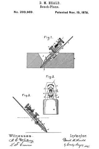
The cap, connected, as usual, with the plane-iron, is provided with a recess to receive the end of a cap-screw carried by a slide made adjustable by means of an adjusting-screw in guideways of a plate, f, pivoted within the body of the plane, so that as the slide is moved by the adjusting-screw the plane-iron and cap are moved longitudinally in the throat.
Figure 1 represents, in longitudinal vertical section, a plane provided with my improvements; Fig. 2, a front-end view thereof. Fig. 3 represents a modidcation hereinafter referred to.
As shown in this instance of my invention, the body a of the plane is supposed to be of wood and to be provided with a throat, b, extended therethrough in the usual manner.
The plane-iron c and its cap d are adjustably connected by means of the screw e, as in other planes.
The plane-iron holder f, preferably made of cast metal and pivoted to the body of the plane at g, has formed in it a guide slot or way, h, to receive a slide, i, which is made longitudinally adjustable therein by means of an adjusting-screw, j, preferably a compound screw, as shown in Figs. 1 and 2, it being composed of a coarse-threaded portion, k, fiitted to a lug, l, of the iron holder f, and of a finer-threaded portion, m, fitted to a lug, n, of the slide i. This slide i is provided with a cap-screw, o, having at its end a tenon, p, which enters a recess in the cap d, there being a shoulder on the screw a short distance per face of the cap and hold it and the plane-iron down in contact with the portion q of the body of the plane within the throat.
When the screw o is turned so that the tenon p enters the recess in the cap, it is obvious if the compound screw be turned that it will act upon the slide i and move it in the slot of the holder f and move with it the plane-iron and cap to regulate the degree of their projection below the face of the plane.
It is obvious that the end of screw o might be recessed to receive a tenon projecting from the cap.
By providing the screw j with threads of different pitch its power is increased. Such screw takes the place of the lever or cam commonly used in other adjustable planes.
The compound screw and cap-screw being located above the iron enables it to be more readily adjusted than can be the irons of other planes wherein the adjusting devices are below the iron.
The screw j might be provided with a thread of uniform pitch; but threads of two pitches are preferable. This compound screw is lntended to operate on the principle of the well-known “Hunter screw.”
I claim —
The combination, with the plane-body, of an iron-holder, f, pivoted thereto, a slide fitted to the said iron-holder, an adjusting-screw to move the slide longitudinally in the holder, and a cap-screw, o, carried by the slide, the said cap-screw being adapted to engage the cap d, located below the holder, to thereby adjust it and its attached plane-iron in unison, substantially as described.
In testimony whereof I have signed my name to this specification in the presence of two subscribing witnesses.
DANIEL MILTON HEALD.
Witnesses:
JOHN M. STANYEM,
LEONARD W. FRENCH.


