No. 1,399,631 – Plane-Scraper (Charles J. Lofdahl And Carl A. Lofdahl) (1921)

[paiddownloads id=”730″]1399631


UNITED STATES PATENT OFFICE.

_________________

CHARLES J. LOFDAHL AND CARL A. LOFDAHL, OF JOLIET, ILLINOIS.

PLANE-SCRAPER.

_________________

1,399,631. Specification of Letters Patent. Patented Dec. 6, 1921.
Application filed December 27, 1919. Serial No. 347,754.

_________________

To all whom it may concern:

Be it known that we, CHARLES J. LOFDAHL and CARL A. LOFDAHL, citizens of the United States, residing at Joliet, in the county of Will and State of lllinois, have invented certain new and useful lrnprovenients in Plane-Scrapers, and we do hereby declare the following to be a full, clear, and exact description of the invention, such as will enable others skilled in the art to which it appertains to rnake and use the same.

This invention relates to certain new and useful improvements in a plane scraper and has for its primary object the provision of a device of this character which will be constructed in such rnanner that the blade may be readily adjusted at various angles and securely held in position.

Another object of the invention resides in the provision of a plane scraper of the above stated character which will be constructed so that the blade rnay be readily adusted to present a new edge when required, without the necessity of removing the blade and sharpening the same.

A further object of the invention resides in the provision of a wood scraper provided with an adjustable blade carriage in which the blade may be securely held against chattering thereby making it possible to obtain a much smoother dressed surface.

A further object of the invention resides in the provision of a wood working tool of the above stated character which may be readily employed by carpenters, cabinetmakers and other workmen and which will be light in weight, easy to operate and composed of the minimum number of parts.

With the foregoing and other objects in view as will appear as the description proceeds, the invention consists in the novel combination, arrangement and cooperation of parts as hereinafter more specifically set forth, claimed and shown in the drawings in which:

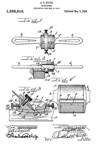
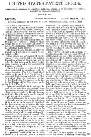
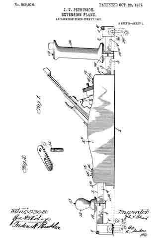
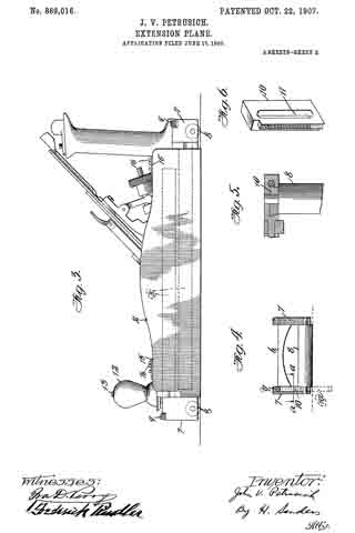
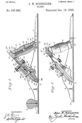
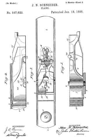
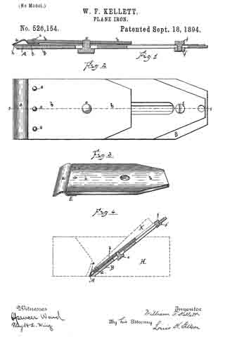
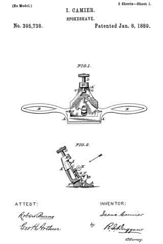
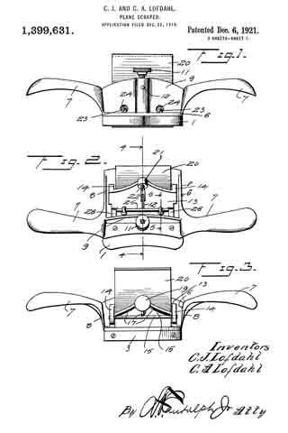
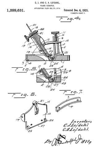
Figure 1 is a front elevation of the plane scraper.

Fig. 2 is a top plan view thereof.

Fig. 3 is a rear elevation.

Fig. 4 is a verticle section on the plane of line 4–4 of Fig. 2.

Fig. 5 is a vertical section on the plane of line 5–5 of Fig. 2.

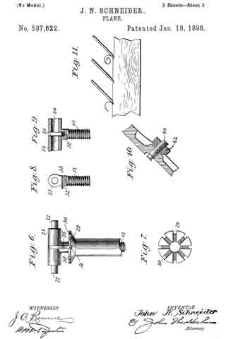
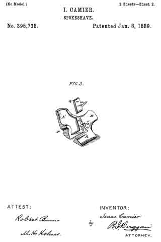
Fig. 6 is a detail perspective of the blade carriage removed, and

Fig. 7 is a detail perspective of the nose cap, removed.

Referring more in detail to the drawings, in which sirnilar reference characters designate corresponding parts throughout the several views, 1 designates the wood bottom having the blade opening 2 formed therein and a nose cap 3 secured upon its rear edge, said nose cap 3 being preferably forrned of metal and having an inturned lower flange 4 resting in the seat 5 formed therefor in the wood bottom, with the lower face of the flange 4 flush with the lower face of the wood bottorn 1, as will be clearly understood by reference to the drawings.

The metallic frame 6 is mounted upon the upper face of the wood bottom 1 and has a pair of oppositely extended curved hand grips 7 projecting from the opposite sides of the frarne 6, it being understood that the frame includes upwardly extended. side members 8 from vvhich the handles 7, extend at the forward corners of said members 6.
The frame also includes a front upstanding rnernber 9 with a central socket 10 formed on the outer face thereof and withln which is threaded a set screw 11, the lower end of which is adapted for binding engagement with the adjusting pin 12, which latter is pivoted to the front plate 13 of the blade carriage, said adjusting pin 12 having sliding movement through the front blade 9 and socket 10 in order that the blade carriage may be readily adjusted at any inclined angle desired.

The front plate 13 of the blade carriage has rearwardly extending ears 14 curved by its side portions and through which are extended the opposite ends of a locking rod 15 having binding engagement with the outer or rear face of the back plate 16 of the blade carriage, downward movement of the back plate 16 being limited by the flanges 17 formed on the diverging upper portions of the sides of said back plate 16 and which flanges also serve to reinforce or strengthen the back plate. This back plate 16 has a threaded ear 18 in its uppermost central portion and through which extends the shank of the set screw 19 for engagernent with the rear face of the blade 20 positioned between the front plate 13 and back plate 16 to assist in retaining the plate 20 in proper position within the carriage. The front plate 13 also has an uppermost central portion with a threaded ear 21 opposite the ear 18 of the back plate 15 with a bearing screw 22 adjustably positioned therein to engage the blade 20 at a point practically opposite the portion of the rear face of the blade 20 engaged by the set screw 19. The front plate 13 of the blade carriage also has a pair of lower bearing screws 23 adjustably mounted therein for proper bearing engagement with the front face of the blade 20 near the bottom of the blade carriage to cooperate with the bearing screw 22 when the three bearing screws are properly positioned to prevent chattering of the blade 20 during the use of the tool particularly when the tool is moving on its return stroke previous to another operative or cutting movement of the tool over the work. ln order that the lower bearing screws 23 may be readily adjusted when required, without the necessity of removing the tool carriage, the upstanding front member 9 is provided with a pair of spaced openings 24 opposite the heads of the screws, 23, for the using of a screw driver or other instrument required to readjust the screws 23.

In order that the carriage for the blade 20 may be readily adjusted in various inclined positions, the carriage is mounted upon a pivot rod or hinge rod 25 which passes through hinge ears 26 depending from the forward lower corners of the front plate 13 of the carriage and connected by the lower outwardly and upwardly curved lower edge of the front plate 13, which also serves to properly inclose the hinge rod 25 and protect the same from shavings which may become caught around the same. The turned lower edge of the plate 13 is indicated by the numeral 27. The ends of the hinge pin 25 are mounted in the downwardly extended portion 28 of the frame 6, in the forward portion of the blade opening 22 of the wood bottom 1 and which portion of the frame 6 extends through said opening 2 with a part thereof presenting a smooth lower face flush with the lower face of the bottom 1, thereby providing a blade and bottom protecting wearing strip 29 in the forward side of the blade opening 2.

It will be understood that the frame 6 and nose cap tl may be secured to the wood bottom 1 by screws or any other suitable means. lt will also be readily seen that by loosening the set screw 11, the blade carriage may be readily moved on the hinge pin 25 to adjust the incline of the blade and in order to raise or lower the blade in the carriage or remove the blade therefrom, it is simply necessary to loosen the set screw 19 in the back plate 16.

From the foregoing, taken in connection with the accompanying drawings, the complete operation of this plane scraper and the advantages of the novel features thereof will be readily apparent to those familiar with this art. Further detail description of the device is therefor believed to be unnecessary.

While the preferred embodiment of the invention has been illustrated and described, many minor changes in the details of construction and arrangement of parts may be resorted to within the scope of what is claimed without departing from the spirit of the invention.

What is claimed is :–

A frame, a rod spanning said frame, a front plate having a turned edge journaled on said rod, means associated with said plate and said frame to secure the plate in adjusted positions, ears extending from the plate, a rod mounted by said ears, a back plate intermediate said last rod and the adjacent portion of the front plate, flanges on the back plate resting on the second mentioned rod at one end, a blade intermediate the front plate and back plate of a width less than the width of the space between said plates, screws mounted by both of said plates and enagageable against the blade on opposite sides to vary the angularity thereof, and a screw on the front plate engageable with the blade to urge it against the back plate at a distance from the first mentioned screws.

In testimony whereof we affix our signatures in presence of two witnesses.

CHARLES J. LOFDAHL.
CARL A. LOFDAHL.

Witnesses:
JAMES G. SMITH,
NELS OLSON.

No. 1,332,919 – Spokeshave (Adolph P. Ritter) (1920)

[paiddownloads id=”725″]1332919


UNITED STATES PATENT OFFICE.

_________________

ADOLPH P. RITTER, OF CHICAGO, ILLINOIS.

SPOKESHAVE.

_________________

1,332,919. Specification of Letters Patent. Patented Mar. 9, 1920.
Application filed March 10, 1919. Serial No. 281,666.

_________________

To all whom it may concern:

Be it known that I, ADOLPH P. RITTER, a citizen of the United States, and a resident of the city of Chicago, in the county of Cook and State of Illinois, have invented certain new and useful Improvements in Spokeshaves; and I do hereby declare that the following is a full, clear, and exact description of the same, reference being had to the drawings and to the numerals of reference marked thereon, which form a part of this specification.

This invention relates to an improved type of spokeshave or wood shaving tool, whereon a gage is adjustably mounted and releasably locked in an adjusted position to permit the spoke-shave to be operated to cut a groove of a predetermined width in a piece of wood.

It is an object of this invention to provide a spoke-shave with an adjustable groove gage.

It is also an object of the invention to construct a spoke-shave to permit a gage to be slidably mounted thereon to facilitate the cutting of grooves of uniform width.

Another object of the invention is the construction of a wood shaving tool wherein an adjustable gage mounted on the groove body of the tool is adapted to be held in an adjusted position by means of retaining screws which are positioned to engage in the body grooves.

A further object of this invention is the construction of a spokeshave wherein the margins of the knife slot are provided with scale markings to permit a gage on said spoke-shave to be set in an adjusted position whereby a groove of uniform width can easily be cut by the spoke-shave.

It is furthermore an object of the invention to provide a spoke-shave with an adjustable gage adapted to be set by means of a divided scale so that a groove of uniform width may be conveniently cut in a piece of wood by the spoke-shave blade.

It is an important object of this invention to provide a right and left handed spoke-shave of simple construction adapted to be used with or without an adjustable gage.

Other and further important objects of the invention will be apparent from the disclosures in the drawings and specification.

The invention (in a preferred form) is illustrated in the drawings and hereinafter more fully described.

On the drawings :–

Figure 1 is a bottom plan view of a spoke-shave embodying the principles of this invention.

Fig. 2 is a rear side elevation thereof showing the same set for cutting a groove of a predetermined width in a block of wood.

Fig. 3 is an enlarged detail section taken on line 3–3 of Fig, 2, with parts in elevation.

Fig. 4 is an enlarged bottom plan view of the spoke-shave with the handles broken od and with the gage removed to show the scale markings.

As shown on the drawings :–

The spoke-shave is made of metal and comprises a body portion or stock 1, having handles 2 secured on opposite ends thereof. The handles may be adjustable if preferred. The bottom surface 3, of the stock 1, is smooth and slightly convexed and is provided with a longitudinal slot 4. Each of the longitudinal margns bordering the slot 4, is provided with a divided scale 5, as clearly shown in Fig. 4. Formed in the stock 1, is an inclined surface 6, having a threaded aperture formed therein. Resting upon the inclined surface 6, is a knife or blade 7, provided with an opening 8, and having the cutting edge positioned to project through the slot 4. A retaining plate 9, is removably placed above the blade 7, and is provided with an integral passaged boss or collar 10. To removably hold the blade 7, and the plate 9, in position, a screw bolt 11, is engaged through the passage collar 10, and through the blade opening 8 and is removably threaded into the threaded opening provided for the purpose in the stock 1. The head of the retaining screw bolt 11, is knurled to permit easy operation of said bolt. The slot 8, permits the blade 7, to be adjusted when the bolt 11, is loosened.

Cut or formed in each of the longitudinal sides of the stock 1, is a guide groove 12, which extends the whole length of the stock and is open at both ends. A channel shaped metal gage 13, is provided, having the ends 14 thereof, bent at an angle and provided with integral guide teeth or tapered projections 15, on the inner surfaces thereof to slidably engage in the stock grooves 12, as shown in Fig. 3. The gage is curved complementally with the convex surface 3, of the stock. Each of the gage ends 14, is provided with a threaded passage to permit a knurled head set screw 16, to be removably or adjustably threaded therethrough to permit the inner end of the screw to lockingly engage in one of the stock grooves 12, for the purpose of holding the gage locked against movement in an adjusted position. As shown in Figs. 2 and 3, the spoke-shave is positioned to out a groove or rabbet in a wooden block 17. A notch or recess 18, is provided in the imier surface of the gage 13, to permit the gage to clear the cutting edge of the blade 7.

The operation is as follows :–

The spoke-shave may be made of steel or any other desired metal and the two scales 5, provided on the opposite margins of the slot 4, afford a ready means for setting the adjustable gage 13, in any desired position on the stock 1. To set the gage for cutting a groove in the block of wood 17, the gage screws 16, are loosened and the gage is then moved on the stock 1, until the guiding side of the gage is disposed to register with a selected division marking on the scales 5. As shown in Fig. 1, the gage is set at five-eighths of an inch. The gage is held locked against movement in an adjusted position on the stock 1, by simply tightening the set screws 16, which frictionally engage on the stock grooves 12.

To cut a groove of a selected width in the block of wood 17, the spoke-shave is placed as shown in Fig. 2, with one side of the gage abutting the side of the block to act as a guide for the spoke-shave. The spoke-shave is operated by means of the handles 2, and the cutting edge of the blade 7, will out a groove of uniform width in the block 9. The spoke-shave may be used as either a left handed or right handed tool, and the gage may be set with respect to either ends of the scales 5. The spoke-shave may be used on either straight or curved pieces of wood. When desired, the gage may be completely removed from the stock 1, and the spoke shave used without the gage.

I am aware that many changes may be made, and numerous details of construction varied through a wide range without departing from the principles of this invention, and I therefore do not purpose limiting the patent granted otherwise than necessitated by the prior art.

I claim as my invention :–

The combination with a spoke-shave having similar guide grooves in the sides thereof, of a gage, means integrally formed on said gage adapted to slidably engage in said guide grooves and thus maintain the gage in slidable contact with the spoke shave, and set screws projecting through said means and adapted to engage in said grooves to hold said gage locked against movement in an adjusted position on said spoke-shave.

In testimony whereof I have hereunto subscribed my name in the presence of two subscribing witnesses.

ADOLPH P. RITTER.

Witnesses:
LAWRENCE REIBSTEIN,
SPENCER W. GIBBS.

No. 1,157,594 – Bench Plane (Theodore G. Selleck) (1915)

[paiddownloads id=”705″]1157594


UNITED STATES PATENT OFFICE.

_________________

THEODORE G. SELLECK, OF CHICAGO, ILLINOIS, ASSIGNOR OF ONE-HALF TO JOHN L. DEPPEN, OF CHICAGO, ILLINOIS.

BENCH-PLANE.

_________________

1,157,594. Specification of Letters Patent. Patented Oct. 19, 1915.
Application filed January 26, 1914. Serial No. 814,479. Renewed March 17, 1915. Serial No. 15,055.

_________________

To all whom it may concern:

Be it known that I, THEODORE G. SELLECK, a citizen of the United States, residing at Chicago, in the county of Cook and State of Illinois, have invented certain new and useful Improvements in Bench-Planes, of which the following is a specification.

This invention relates to bench-planes, and its object is to provide a structure which permits the bit to be quickly and easily removed for sharpening, without disturbing the adjusting means thereof.

The invention also has for its object to provide novel and improved means for adjusting the bit.

Other objects and advantages of the invention will be pointed out in the detailed description appearing hereinafter, and in order that the same may be better understood, reference is had to the accompanying drawings, in which —

Figure 1 is a side elevation of a bench plane constructed in accordance with the present invention; Fig. 2 is a longitudinal section on the line 2–2 of Fig. 4; Fig. 3 is a sectional detail showing a slightly modified form of bit; Fig. 4 is a section on the line 4-4 of Fig. 1; Fig. 5 is a section on the line 5–5 of Fig. 1, and Fig. 6 is a section on the line 6–6 of Fig. 4.

Referring specifically to the drawing the stock of the plane is of conventional form, the same comprising a sole 10, side or check-pieces 11, a rear hand grip 12 and a forward knob 13. The sole has a slot 14 through which the bit 15 protrudes.

The bit 15 is carried by a member 16 which is pivotally mounted between the side pieces 11 in a manner to be presently described. By thus pivoting the bit carrier the same may be rotated to take the bit out of the slot 14 as shown by dotted lines in Fig. 1, the bit then pointing upward and being free of the side pieces, in which position it is readily accessible for the purpose of removal. The axis of rotation of the bit carrier is transverse of the stock. The bit carrier 16 tapers toward the end which carries the bit 15, said end having a dovetailed transverse groove 17 in which the bit seats and is held, the rear portion of the bit being shaped to fit in the groove.

The following clamping means for the bit 15 is provided: In the under side of the bit carrier 16 is a threaded aperture to receive a screw 18. This aperture is so located that it intersects the inner end of the groove 17, thus allowing a portion of the back of the bit to extend into the aperture, at the place where the beveled side of the screw head 19 seats, the aperture being countersunlr to accommodate said screw head. By working the screw inward, the beveled side of the head is forced against the back of the bit, and the bit is forced forward to a rigid seat in the groove. The bit can be readily removed by sliding it along the groove, after backing the screw.

Fig. 3 shows a slightly modified form of bit, its inner end having a shoulder 20 which abuts against the end of the bit carrier 16. The bit carrier 16 is a hollow casting having side openings 21. The sides of the bit carrier are flat and parallel, and its width is such that it has a small amount of side play between the side pieces 11. The bit carrier is carried by a yoke, the side arms 22 of which latter seat in longitudinal grooves 23 in the sides of the bit carrier. The connecting bar 24 of the yoke extends across and in spaced relation with the rear end of the bit carrier, or that end which is opposite the end carrying the bit 15. The bar 24 has, midway between its ends, an aperture in which is held an adjusting screw 25 which is threaded through a block 26 carried by the bit carrier, the latter having an aperture 27 to accommodate the inner end of the screw. The screw is held against travel in the direction of its length by its head 27a and a collar or washer 28 located, respectively, on opposite sides of the bar 24. Thus, it will be seen that when the screw is operated, the bit carrier is moved baclr and forth between the arms 22 to regulate the degree of protrusion of the bit through the slot 14.

The yoke is pivoted to the side pieces 11, which provides the hereinbefore described pivotal support for the bit carrier 16. The pivotal connection is made by pivot screws 29 passing through the side pieces and threaded into the arms 22 of the yoke. The heads 30 of the pivot screws are countersunk in the side pieces, and their shanks are devoid of threads where they pass through the side pieces, which enables the bit carrier to be swung without causing the pivot screws to tighten up.

The block 26 seats against the rear end of the bit carrier 16 between outstanding spaced ribs 31 and 32 on the latter, and it is pivoted at one end so that it may swing outward from the end of the bit carrier. The pivotal connection is made by a pin 33 passing through the block and held at its ends in the ribs 31 and 32. The free end of the block is shaped to form a half nut, the thread 34 of which fits in the groove of a worm 35 seating in a recess in the end of the bit carrier, and mounted on a pivot screw 36 carried by the latter. The worm carries a small projecting finger-piece 37 for operating the same.

Upon turning the worm 35 in one direction, by means of the finger-piece 37, the block 26 swings outward from the bit carrier 16, as shown by dotted lines in Fig. 4, and it is swung back toward the bit carrier upon turning the worm in the opposite direction. This movement of the block reults in giving the bit carrier a sidewise tilt to line up the slot 14.

In order to prevent the bit carrier 16 from rocking when the tool is in use, a stout spring latch 38 is provided, the same being secured to the sole 10 and having its free end offset and shaped to snap under the bar 24. When the latch is in holding position, the rear end of the bit carrier cannot swing downward, and it is prevented from swinging upward by the bit 15 engaging the rear wall of the slot 14. Upon disengaging the latch from the yoke bar, the bit carrier may be swung to the dotted line position shown in Fig. 1, for the purpose stated hereinbefore.

I claim:

1. A bench-plane comprising a stock having side-pieces, a yoke pivotally mounted between the side-pieces, a bit carrier carried by the yoke and adjustable in the direction of its length, and means for locking the yoke.

2. A bench-plane comprising a stock having side-pieces, a yoke pivotally mounted between the side-pieces, a bit carrier carried by the yoke, an adjusting screw carried by the yoke and having a threaded engagement with the bit carrier, and means for locking the yoke.

3. A bench-plane comprising a stock having side-pieces, a yoke pivotally mounted between the side-pieces, a bit carrier having longitudinal side grooves, in which the yoke arms seat, means for adjusting the bit carrier in the direction of its length, and means for locking the yoke.

4. A bench-plane comprising a stock having side-pieces, a yoke pivotally mounted between the side-pieces, a bit carrier carried by the yoke and adjustable sidewise and in the direction of its length, and means for locking the yoke.

5. A bench-plane comprising a stock having side-pieces, a yoke pivotally mounted between the side-pieces, a bit carrier carried by the yoke, a pivoted member carried by the bit carrier, an adjusting screw carried by the yoke and having a threaded engagement with the pivoted member, a worm carried by the bit carrier and having a threaded engagement with the free end of the pivoted member, and means for locking the yoke.

6. A bench-plane comprising a stock, a bit carrier, a support for the bit carrier carried by the stock, a pivoted member carried by the bit carrier, an adjusting screw carried by the support and having a threaded engagement with the pivoted member, and a worm carried by the bit carrier, and having a threaded engagement with the free end of the pivoted member.

In testimonv whereof I affix my signature in presence of two witnesses.

THEODORE G. SELLECK.

Witnesses:
S. J. LEHRER,
H. W. BATCHELOR.

_________________

Copies of this patent may be obtained for five cents each, by addressing the “Commissioner of Patents, Washington, D. C.”
_________________

No. 869,016 – Extension-Plane (John V. Petrusich) (1907)

[paiddownloads id=”649″]869016


UNITED STATES PATENT OFFICE.

_________________

JOHN V. PETRUSICH, OF CHICAGO, ILLINOIS.

EXTENSION-PLANE.

_________________

869,016. Specification of Letters Patent. Patented Oct. 22, 1907.
Application filed June 17, 1907. Serial No. 379,311.

_________________

To all whom it may concern:

Be it known that I, JOHN V. PETRUSICH, a citizen of the United States, residing at Chicago, in the county of Cook and State of Illinois, have invented a new and useful Extension-Plane, of which the following is a specification.

This invention relates to improvements in planes.

It is well known that carpenters and others using this class of tool find occasion to use several sizes of the same and the object of this invention is to provide what may be termed an extension plane or a plane in which the several essential sizes of the tool are combined in one.

With this and other objects in view the invention consists in the construction and combination of parts to be hereinafter described, pointed out and claimed in the following specification and illustrated in the accompanying drawings, in which:–

Figure 1 is a side elevation of the device complete. Fig. 2 is a detail of a slotted bar and pin therefor used for locking the extension members. Fig. 3 is a view similar to Fig. 1 showing in dotted lines the position of the extension members when the plane is closed. Fig. 4 is an end of the device partly in section and taken on line d–d Fig. 9. Fig. 5 is a view in section of Fig. 4 taken on line a–a. Fig. 6 is a detail perspective of the rack employed in the extension portion of the device. Fig. 7 is a plan view of the plane closed. Fig. 8 is a front view of Fig. 7, partly in section, and taken on the line b–b. Fig. 9 is a section taken on line c–c of Fig. 7.

Like reference characters indicate corresponding parts throughout the several views.

The reference numeral 2 represents a plane of ordinary or preferred construction having longitudinal sockets 2a opening in either extremity of the side walls 2b of the plane and running horizontally and parallel with each other as shown in Fig. 3.

The numeral 3 represents extension rods adapted to fit slidably into the sockets 2a and having graduations 4 on their lateral surfaces for measuring off the work. Roller-carriers 7 are provided at the external extremities of the extension rods as shown in section in Fig. 4 and as shown complete in Fig. 1, in which are pivoted the rollers 8 for the purpose of carrying the plane smoothly over the work. A brace 6 connects either pair of roller-carriers as shown in Fig. 7 for the purpose of holding the extension rods rigidly parallel.

Either roller-carrier arranged on either left-hand extension rod is recessed on the surface adjacent the roller so that it may carry a rack 10 provided with a slot 11 which engages the pivot of the roller 8. Each left-hand roller-carrier is fiuther provided with a worm 9 which engages the rack 10 for the purpose of raising and lowering the same as shown in detail in Figs. 4 and 5. When the rack 10 is dropped below the lelt-hand edge of the work it serves as a lateral drop guide to keep the plane flush with that edge of the work as shown in Fig. 1.

12 represents a knob of the plane provided with a screw 13 running the entire length of the same and protruding beyond the lower extremity thereof.

14 represents the upper section of a clamp slidably arranged on the extension rods and provided with a threaded aperture to receive the screw 13 protruding from the knob 12 which is seated on said portion of the clamp.

14a is the lower section of the clamp arranged on the extension rods in a manner similar to the upper portion and provided with a threaded aperture to receive the screw 13 that extends through the upper portion of the clamp. By turning the knob 12 to the right the sections of the clamp 14 and 14a are drawn together and are caused to grip the extension rods firmly thus affording rigid handles to the plane.

15–15 represents a pair of slotted bars arranged on the side walls of the plane by means of the screws 16 movable with said bars. The screws 16 extend vertically through the side walls of the plane to the sockets 2a and when the slotted bars are turned at right angles with the side walls of the plane the screws 16 engage the extension rods resting within the said sockets and hold them firmly.

17 represents a horizontal connecting link pivoted at 18 and engaging the slotted bars 15 in the manner shown in Fig. 7. By turning this horizontal link until it lies in a straight angle with the two slotted bars it will cause the screws 16 to engage the extension rods as above described. Thus it will be seen, the extension rods can be partly withdrawn from their sockets and locked in that position.

Either end of the plane is provided with similar extension apparatus and hence a description of that on one end is a description of the apparatus on the other.

Having fully described my invention, what I wish to claim and secure by Letters Patent of the United States is:

1. In a plane, extension means journaled in the side walls thereof, a sliding clamp mounted on said extension means, a knob seated on said sliding clamp and supporting means terminally carried by said extension means substantially as described.

2. In a plane, extension means journaled in the side walls thereof, an extension stop carried on the side walls thereof, a sliding clamp mounted on said extension means, a knob seated on said sliding clamp, roller-carriers terminally arranged on said extension means, a roller pivoted within said roller-carriers and a lateral drop guide carried by said roller-carrier substantially as described.

3. In Combination with a plane having longitudinal sockets in the side walls thereof, sliding extension rods arranged therein, a. sliding screw-actuated clamp arranged on said extension rods, a knob seated on said clamp by which the same may be anchored or released, roller-carriers terminally carried by said extension rods, a roller pivotally carried by said roller carriers, a brace 6 connecting said roller-carriers and a worm and rack carried by said roller-carriers substantially as described.

In testimony that I claim the foregoing as my own, I have hereto affixed my signature in the presence of two witnesses.

JOHN V. PETRUSICH.

Witnesses:
ROSE GREENBERG,
FREDERICK RINDLER.

No. 779,392 – Plane (Otto Bjordal) (1905)

[paiddownloads id=”615″]779392


UNITED STATES PATENT OFFICE.

_________________

OTTO BJORDAL, OF CHICAGO, ILLINOIS.

PLANE.

_________________

SPECIFICATION forming part of Letters Patent No. 779,392, dated January 3, 1905.
Application filed April 2, 1904. Serial No. 201,362.

_________________

To all whom it may concern:

Be it known that I, OTTO BJORDAL, a citizen of the United States, residing at Chicago, in the county of Cook and State of Illinois, have invented a new and useful Plane, of which the following is a specification.

My invention relates to improvements in planes which are provided with an adjustable blade and a handle to manipulate the same; and the objects of my improvement are, first, to provide a cam under the lower end of the blade to adjust the same; second, to provide a set-screw to assist in adjusting the blade; third, to afford facilities for shifting the upper end of the blade to either side; fourth, to provide a cheap and simple construction of the cap cam-lever; fifth, to provide means whereby the plane-handle can be filted into any desired position, and other objects which will become apparent from the description to follow. I attain these objects by the construction shown in the accompanying drawing.

Heretofore planes of this class were provided with means for adjusting the blade which required the blade to slide longitudinally while being tightly clamped in position. This construction often made it impossible to make a fine adjustment. With my construction the adjustment of the blade is accomplished by slightly bending or springing the blade and without moving the blade longitudinally in its bearing. This is made possible by placing a cam-shaft under the lower end of the blade, which has a lever connected to one end, and by moving the said lever forward and back the cam-shaft is rocked in its bearing so as to lower and raise the cutting edge of the blade. To securely hold the blade against any longitudinal movement, I provide a set-screw in the bed or frame of the plane, which is brought to bear against the head of the screw, which locks the blade and fore guide together. This construction enables the user to adjust the cutting edge of the blade to a thousandth part of an inch, or even finer, if found necessary, without the slightest danger of the blade being forced out of the adjustment while the plane is in use, as often occurs with the present construction of planes.

When the cutting edge of the blade is not ground exactly or straight across, it requires that the upper end of the blade be shifted from side to side. I accomplish this side movement by providing a rotatable disk in the blade, the upper exposed side of the disk being provided with a lever or thumb-piece and the lower side of the disk being provided with an eccentric-pin which engages a slot in the bed or frame of the plane.

The cap cam-lever of my device is pivoted in the end of the cap by having two oppositely-extending lugs resting in sockets provided in the cap, and no rivet or pin is used, as is the casein the present construction of planes.

It is often desirable for convenience while working to have the inclination of the handle of the plane changed, depending on the height of the mechanic using the plane and the height of the work from the floor. I make provision for such adjustment by having a curved slotted plate on the body of the plane and a headed bolt on the handle to move in said slot and a means for clamping the bolt securely in any position in the slot.

Referring to the drawing, similar reference characters refer to similar parts.

The body of the plane 10 is provided with the ordinary well or socket 11 for the reception of the blade 12 and its cooperating parts. While I have shown and will describe my invention in connection with a wooden plane it will be understood that the same can be applied to a metal plane.

The blade 12 is clamped tightly to the fore guide 18 in the ordinary manner by the screw 14. A bed-plate or frame 15 is rigidly secured to the oblique bottom of the well 11, and the blade 12 and fore guide 13 are tightly clamped to the same in the ordinary manner by the cap 16 and the cap-screw 17. The cap-lever 18 is pivotally attached to the cap by having its integral lugs 19 set into the sockets 20, provided in the cap 16, the cap 16 being slotted between the sockets 20 to permit the free passage of the lever 18. I provide a leaf-spring 21, riveted to the lower side of the cap, whose free end rests against the under side of the lever 18 and retains the lugs 19 in their cooperating sockets. The leaf-spring 21 also serves as a bearing-surface when the lever is operated. A depression or socket 22 is provided in the upper surface of the bed-plate 15 for the reception of the head of the screw 14, the depression 22 being somewhat larger than the head of the screw 14. A set-screw 23 is secured in the bed-plate 15, so arranged that it can be screwed against the head of the screw 14, and thus force the blade 12 down to any desired adjustment and also serves to prevent the blade from shifting upward when the plane is being used.

The blade 12 is intended to be set by the set-screw 23 so that it will make the very thickest cut desired, and to change the position of the blade to make a finer cut an elliptical or oval-shaped shaft 24 is mounted in a suitable groove in the bed-plate 15 under the lower end of the blade 12, which when rotated in one direction will lift the lower end of the blade 12, reducing the opening between the cutting edge and the body of the plane and when rotated in the reverse direction will allow the lower end of the blade 12 to return to its normal position. In certain constructions it may be desirable to place a plate between the shaft 24 and the lower end of the blade 12. To provide a convenient means for partly rotating the shaft 24, a flat lever 26 is rigidly secured to one end of the shaft 24 and extends upward beside the blade 12 to within easy reach of the operator.

I prefer to have the relative arrangement of the parts so that when the lever 26 is in its forward position to allow the blade 12 to assume its normal and lowermost position. To retain the lever 26 in any position, I provide a sheet-metal plate 27 between the lever 26 and the edge of the blade 12, securing it in place by a screw 28, which is screwed into the bed-plate 15, and to assist in holding said plate 27 firmly the shaft 24 passes through a hole in said plate. The upper edge of the plate 27 is bent out toward the lever 26 and is provided with ratchet-teeth 29, and that portion of the lever 26 contacting with the teeth 29 is provided with an extending edge or lip to cooperate with said teeth. The lever 26 is attached to the shaft 24 in such a manner that it will normally be held against the teeth 29, and when it is desired to move the lever forward it is first sprung out away from the teeth 29. To relieve this side strain on the lever from coming on the connection between the lever 26 and the shaft 24 and also to assist in holding the lever 26 against the teeth 29, a portion of the lower edge of the plate 27 is folded back against the lever 26, as at 30.

When the cutting edge of the blade 12 is not parallel with the base of the plane, it becomes necessary to move the upper end of the blade 12 to one side or the other, as the case may require, and to accomplish this side movement relative to the bed-plate 15 I provide a hole 31 in the blade 12, in which a disk 32 is mounted to rotate in the plane of the l blade. The under side of the disk 32 is provided with the eccentric-pin 33, which extends into the groove 34, provided in the bed-plate 15. A lever or thumb-piece 35 is provided on the upper side of the disk 32 to conveniently rotate the same. The disk 32 may be rotatably secured in the hole 31 in any desired manner; but I have found that a simple and cheap mode of effecting this is to have the under side of the hole beveled, as seen in Fig. 2, and have the edge of the disk swaged out at two points, as seen in Fig. 4, to rest against the beveled portion of the hole 31 and prevent the disk from being removed from said hole. The hole 31 may be provided with two notches which will register with the two swaged-out points on the disk when the disk is turned to a certain position, and thus permit the removal of the disk from the hole.

The blade 12 from constant use and regrinding is reduced in length, and to provide for the side adjustment of the blade at different lengths a plurality of holes 31 may be provided in the blade.

The handle 36 of the plane is made adjustable by securing a slotted plate 37 to the top of the body of the plane 10. A groove 33, larger than the slot 39, is made in the plate below the slot, and a bolt 40, secured in the handle, passes through the slot 39 and has its head resting in the groove 38. To secure the bolt 40 in the handle 36 and at the same time clamp the same to the plate 37, I provide an elongated nut 42 to be screwed on the end of the bolt 40 and rest against a shoulder 43, provided in the handle 36. The nut 42 has its end exposed and arranged to he turned by a wrench or screw-driver. The plate 37 and therefore the groove 38 and slot 39 are made to coincide with the arc of a circle, and to change the inclination of the handle 36 with relation to the plane 10 the nut 42 is loosened, the handle is moved along on the plate 37 to the desired position, and then the nut 42 is again tightened.

Having thus fully described my invention, what I claim as new, and desire to secure by Letters Patent of the United States, is —

1. In a plane, means for adjusting the cutting edge of the blade comprising a cam-shaft extending parallel with said cutting edge so arranged that the cutting edge of the blade will be raised and lowered by rotating said shaft.

2. In a plane, a blade clamped against the body, a groove in the body under the lower edge of the blade a cam-shaft resting in said groove, and a hand-lever rigidly secured to said cam-shaft, said parts being so connected and arranged that the cutting edge of the blade will be sprung by moving said hand-lever.

3. In a plane, a blade clamped against the body, a set-screw secured to the blade, a set-screw adjustably secured in the body contacting with the former set-screw to limit the longitudinal movement of the blade, a groove in the body under the lower edge of the blade, a cam-shaft resting in said groove, a friction-plate between the cam-shaft and the blade, a hand-lever rigidly secured to one end of said cam-shaft, and a rack secured to the body with which said hand-lever contacts to be retained in position, said parts being so arranged that the movement of the lever in one direction will spring the blade to raise the cutting edge, and a movement of said lever in the opposite direction will lower said cutting edge.

In testimony whereof l have signed my name to this specification, in the presence of two sub scribing witnesses, this 28th day of March 5 1904, at Chicago, Illinois.

OTTO BJORDAL.

Witnesses:
R. J. JACKER,
R. R. SYMONS.

No. 763,527 – Cutting-Tool (Augustus E. Venn) (1904)

[paiddownloads id=”604″]763527


UNITED STATES PATENT OFFICE.

_________________

AUGUSTUS E. VENN, OF CHICAGO, ILLINOIS.

CUTTING-TOOL.

_________________

SPECIFICATION forming part of Letters Patent No. 763,527, dated June 28, 1904.
Application filed October 5, 1903. Serial No. 175,902. (No model.)

_________________

To all whom it may concern:

Be it known that I, AUGUSTUS E. VENN, a citizen of the United States, residing at Chicago, in the county of Cook and State of Illinois,have invented certain new and useful Improvements in Cutting-Tools, of which the following is a specification, reference being had to the accompanying drawings.

My invention relates to cutting-tools, and particularly to tools adapted to cut grooves in wood or other material to be operated upon; and its object is to provide a new and improved means by which, by the rotation of the cutter in the tool, grooves of different shapes may be cut in the work.

In the drawings, Figure 1 is a longitudinal vertical section on line 1 1 of Fig. 2. Fig. 2 is a top or plan view with one of the handles broken away. Fig. 3 is an enlarged detail, being an isometric view of a part of the support by means of which the cutter is secured to the stock. Fig. 4 is an enlarged detail, being an isometric view of a cross-bar by which one end of the support shown in Fig. 3 is secured to the stock. Fig. 5 is a detail, being a view of the gage, partly broken away; and Fig. 6 is a diagrammatic view showing several shapes which may be given to the cutting edge of the cutter.

As shown in the drawings and as preferably constructed, my invention is embodied in the form of a grooving-plane.

7 indicates the stock, and 8 the bit or cutter.

9 indicates a support which is provided with a cross-piece 10, preferably integral therewith, having its two ends bent up at right angles, as is best shown in Fig. 3, and of such length as to fit closely between the sides of the stock 7. The under side of the support 9 is rounded out, as is best shown in Fig. 3, to conform to the shape of the handle of the bit or cutter 8.

11 indicates a cross-piece which is bent at right angles at its ends and is of such length that the bent-up ends may fit snugly between the sides of the stock 7.

The support 9 is provided at the opposite end from the cross-piece 10 with a projection 12, and the cross-piece 11 is provided with a recessed portion 13 on its upper side, into which the projection 12 will snugly fit.

14 indicates a stirrup which is adapted to surround the rounded portion of the bit or cutter 8 and to pass around the support 9. It is provided on its upper surface with a screw-threaded opening into which a thumb-screw 15 may be screwed.

The bent ends of the cross-piece 10 and of the cross-piece 11 are provided with suitable screw-threaded openings by means of which they may be secured between the sides of the stock. The projection 12 of the support 9 is provided with screw-threaded openings and the recessed portion of the cross-piece 11 with corresponding openings, through which screws may pass to engage the screw-threaded openings in the projection 12 for the purpose of fastening the parts together.

The support 9 is placed between the sides of the stock with its hollowed rounded surface facing downward and is secured to the stock by suitable screws passing through the sides of the stock and into the screw-threaded openings in the bent ends of the cross-piece 10. The stirrup 14 is then placed in position around the support 9, the cross-piece 11 placed in position and fastened by screws to the sides of the stock, and the projection 12 is secured in place in the recess 13 by means of suitable screws.

The bit 8 is cylindrical at its upper end and is provided at its lower end with a cutting portion 16. The bit is provided with a proper clearance above the cutting portion, through which the shavings may pass, as is best shown in Fig. 2.

The cutting edge of the tool may be of various shapes, of which several are illustrated in Fig. 6. The cutter, being placed in position between the support 9 and the stirrup 14, may be adjusted longitudinally of itself, so that a proper amount of the cutting edge may project below the sole of the stock 7 through the usual opening therein, and is locked in position by turning the thumb-screw 15, which will cause the stirrup 14 to move up toward the support 9, firmly binding the cylindrical portion of the cutter between the stirrup and the support. It will be obvious that by rotating the cutter 8 upon its longitudinal axis, which it is obvious can be accomplished by loosening the set-screw 15 and then screwing it home when the desired amount of rotation is made, a different-shaped cutting edge will project below the sole of the stock 7 and a different-shaped groove thereby cut in the work.

17 (see Fig. 2) indicates handles, of which one is cut away upon one side to show the gage hereinafter described. The handles are secured to the stock in any appropriate way.

18 indicates a pin which is cylindrical in shape and has upon its ends screw-threaded portions 19. The sides of the stock 7 are provided with cylindrical openings 20 21, through which the cylindrical pin 18 may pass, and opposite the openings 20 21 are screw-threaded openings 22 23, which are adapted to engage with the screw-threaded ends of the pin.

24 indicates a gage which is provided with a suitable opening through which the pin 18 passes and which is secured in any desired position upon the pin 18 by means of a set-screw 25. It will be obvious that by this construction the gage can be used upon either side of the tool.

That which I claim as my invention, and desire to secure by Letters Patent, is —

1. The combination with a support, of a bit-iron mounted in said support adjustable longitudinally of itself therein and adapted to be rotated on its longitudinal axis and by its rotation to present a different-shaped cutting edge to the work, and means for locking said bit-iron in any desired position, substantially as described.

2. The combination with a plane-stock, of a bit-iron mounted in said stock adjustable longitudinally of itself therein and adapted to project its cutting edge below the sole of said stock, said bit-iron being rotatable on its longitudinal axis and having a cutting edge of such shape that by said rotation of said bit-iron grooves of different shape may be cut, and means for locking said bit-iron in any desired position, substantially as described.

3. The combination with a support of a cutting-tool adjustably mounted in said support adapted to be rotated on its longitudinal axis and having a tubular end provided with a cutting edge adapted by the rotation of said cutting-tool to present a different-shaped cutting edge tothe work, and means for locking said cutting-tool in any desired position, substantially as described.

4. The combination with a stock, a support secured to said stock, a stirrup surrounding said support, a set-screw carried by said stirrup adapted to bear upon one side of said support, a cutter having a shank adapted to be engaged between said support and said stirrup, said cutter being adapted to be rotated upon its longitudinal axis and having a cutting edge of such shape that by the rotation of said cutter grooves of different shape may be cut, substantially as described.

AUGUSTUS E. VENN.

Witnesses:
MINNIE A. HUNTER,
HELEN M. COLLIN.

No. 717,883 – Hand Gaining Tool (Robert P. Mathews) (1903)

[paiddownloads id=”577″]717883


UNITED STATES PATENT OFFICE.

_________________

ROBERT P. MATHEWS, OF HARVARD, ILLINOIS, ASSIGNOR OF TWO-THIRDS
TO MARTIN A. STAFFORD AND HARRY E. STAFFORD, OF HARVARD, ILLINOIS.

HAND GAINING-TOOL.

_________________

SPECIFICATION forming part of Letters Patent No. 717,883, dated January 6, 1903.
Application filed April 7, 1902. Serial No. 101,835. (No model.)

_________________

To all whom it may concern:

Be it known that I, ROBERT P. MATHEWS, a citizen of the United States, residing at Harvard, in the county of McHenry and State of Illinois, have invented certain new and useful Improvements in Hand Gaining-Tools; and I do hereby declare the following to be a full, clear, and enact description of the invention, such as will enable others skilled in the art to which it appertains to make and use the same.

This invention relates to hand gaining-tools, the object in view being to provide a manually-operated implement adapted to cut a groove of any desired depth in lumber either in a rectilinear or curvilinear path. Incidental to the primary object of the invention the aim of the invention is to so form the cutting-bit as to locate the advance cutters and following chisel in close relation to each other, at the same time doing away entirely with any material or projection in advance of the cutters, in rear of the chisel, and between the cutters and chisel, thus enabling the tool to be advanced and to form a groove either in a straight, curved, or tortuous path.

Another object of the invention is to provide the bit of the implement with a clearance-throat the edge of which is beveled on one side, so as to discharge the shavings or cuttings laterally. In connection with the gaining-tool depth and side or lateral gages are employed, the same being made adjustable to give a wide range.

With the above and other objects in view, the nature of which will more fully appear as the description proceeds, the invention consists in the novel construction, combination, and arrangement of parts,as hereinafter, fully described, illustrated, and claimed.

In the accompanying drawings, Figure 1 is a perspective view of a hand gaining implement constructed in accordance with the present invention, showing the work in dotted lines. Fig. 2 is a detail perspective view of the bit, guide-post, and a portion of the shank. Fig. 3 is a vertical section through that portion of the bit which carries the cutters.

Like reference numerals designate corresponding parts in all the figures.

The hand gaining-tool contemplated in this invention comprises, essentially, a handle 1, from which extends a shank 2, which terminates in a C-shaped bit 3. The bit, which is illustrated in detail in Fig. 2, is shown to comprise a vertical or pendent arm 4, which travels in advance of the rest ot the tool and is provided at its lower edge with downwardly-projecting cutters 5, arranged at a distance apart equal to the width of the groove to be formed in the stock. In order to provide for the proper clearance, the lower portion of the arm 4 is thickened or expanded, as indicated in Fig. 3, the outer surfaces of the cutters 5 being in line with the opposite surfaces of the arm 4, while the inner sides of the cutters are beveled to diverge downwardly, as shown. A horizontal arm 6 is connected with the body of the bit and the shank 2 by means of a curved portion 7, and said arm terminates in a chisel-shaped cutting-point 8, which is located in close proximity to the cutters 5, so as to follow directly thereafter and remove the material between the cuts formed by the cutters 5. The horizontal arm 6 is, like the vertical arm 4, widest at the bottom, so as to give the proper clearance and facilitate the operation of the tool. A large opening or throat 9 intervenes between the arms 4 and 6 of the bit to allow the shavings or cuttings to rise, and the edge of said opening is beveled or chamfered at one side, as shown at 10, for the purpose of discharging the shavings or cuttings laterally as it is advanced along the work. Extending upward from the bit is an upright guide-post 11, provided at the top with a laterally-projecting guide-lug 12, which is received in the slot 13 of the shank 14: of a depth-gage 15. This gage is adjustable up and down on the guide-post 11 and vertical arm 4 and is held at any desired adjustment by means of a set-screw 16, the shank of which passes through the slot 13 of the depth-gage and enters a threaded opening 17 in the guide-post. By adjusting the gage 15 any desired depth of cut may be obtained, the tool being operated until the gage 15 moves in contact with the adjacent surface of the work.

At one side the cutting bit or shank is provided with an L-shaped lug 18, which, together with the shank or bit, is provided with a lateral opening, through which passes a stem 19 of a side gage 20, having a plane lower edge 21 and rounded or beveled lower corners 22 to facilitate the movement of said gage through a groove previously formed by the gaining-tool. The stem 19 is adjustable through the opening in the lug 18 and may be held fixedly at any point of adjustment by means of a binding-screw 23, threaded through the upper portion of the lug 18 and adapted to be brought to bear against the stem 19. By means of the side gage and its adjustment the distance between adjacent grooves may be readily gaged.

From the foregoing description it will be seen that no material is left in advance of the cutters 5, nor in rear of the chisel 8, nor between the cutters and chisel, while at the same time the cutters and chisel are located in close relation to each other, which adapts the tool to be advanced in acurved or tortuous path as well as in a rectilinear path, thereby adding to the practical value and utility of the device. The depth and side gages are both easily adjustable, and thereby the depth of cut and the distance between the adjacent groove may be readily and accurately determined.

The hand gaining-tool hereinabove described may be made in various sizes for cutting grooves of different depth and width, and other changes may be made in the form, proportion, and minor details of construction without departing from the principle of the present invention.

Having thus described the invention, what is claimed as new, and desired to be secured by Letters Patent, is —

1. A hand gaining-tool comprising a shank terminating in abit of approximately C form, one arm of the bit being about at a right angle to the shank to occupy a perpendicular position when the said shank is horizontally arranged and terminating in spaced cutters, and the other arm curving away from, thence about parallel with the said shank toward the spaced cutters and terminating in a chisel-edge, substantially as described.

2. A hand gaining-tool comprising a shank terminating in a bit of approximately C form, one arm of the bit being about at a right angle to the shank to occupy a perpendicular position when the said shank is horizontally arranged and terminating in spaced cutters, and the other arm curving away from, thence about parallel with the said shank toward the spaced cutters and terminating in a chisel-edge, and a depth-gage adjustable on the vertical arm of the bit and in a direction at a right angle to the length of the aforesaid shank, substantially as specified.

3. In a hand gaining-tool, a shank, an arm and guide at the outer end of the shank extended in opposite directions therefrom about at a right angle, the arm terminatingin spaced cutters, a second arm curved away from, thence about parallel with the shank toward the said spaced cutters and terminating in a chisel-edge, and a depth-gage adjustable on the said guide, substantially as set forth.

4. A hand gaining-tool comprising a handle, a cutting-bit connected therewith and embodying a chisel-point and oppositely-arranged cutters located in advance of the chisel-point, a guide-post extending upward from the bit, and a depth-gage adjustably mounted on said guide-post, substantially as described.

5. A hand gaining-tool comprising a handle, a cutting-bit connected therewith, a guide-post extending upwardly from the bit and provided at its upper end with a laterally-projecting guide-lug, and a depth-gage provided with a slotted shank embracing the guide-lug, and a set-screw passing through the slotted shank into the guide-post at a distance from the guide-lug, substantially as and for the purpose set forth.

In testimony whereof I affix my signature in presence of two witnesses.

ROBERT P. MATHEWS. [L. S.]

Witnesses:
EUGENE SAUNDERS,
M. J. EMERSON.

No. 706,576 – Plane (Axel L. Lundgren) (1902)

[paiddownloads id=”565″]706576


UNITED STATES PATENT OFFICE.

_________________

AXEL L. LUNDGREN, OF PULLMAN, ILLINOIS, ASSIGNOR OF
ONE-HALF TO HARRY W. WOLFE, OF CHICAGO, ILLINOIS.

PLANE.

_________________

SPECIFICATION forming part of Letters Patent No. 706,576, dated August 12, 1902.
Application filed January 4, 1902. Serial No. 88,462. (No model.)

_________________

To all whom it may concern:

Be it known that I, AXEL L. LUNDGREN, a citizen of the United States, residing in Pullman, Cook county, Illinois, have invented a certain new and useful Improvement in Planes, of which the following is a specification.

The object of this invention is to construct a plane which will be strong and compact in structure, neat in appearance, and easy of adjustment, and the parts of which will, moreover, be firmly and rigidly held in their adjusted positions; and the invention more particularly relates to the means by which this adjustment is accomplished and maintained and to the improvement of the construction and operation of the plane as a whole.

The invention further consists in the features of construction and combination of parts hereinafter described and claimed.

In the drawings illustrating the invention, Figure 1 is a side elevation of the plane of this invention; Fig. 2, a side elevation showing one of the sides of the stock or frame cut away, exposing the adjusting mechanism within; Fig. 3, a top or plan view with the cap or cover removed, and Fig. 4 a top or plan view with the wedge and bit removed from the stock or frame.

The plane of this invention is made with a stock: or frame A, which may be of metal or other suitable material having side walls a, a front end wall a’, a rear end wall a2, beveled at its upper corner, and a bottom or sole a3 for contact with the wood to be planed, and an escape-opening A’ in the side walls and a mouth a4 in the sole to allow for the projection of the bit therethrough and the escape of shavings from within the stock. Between the side walls and abutting against the interior of the rear end wall and the bottom or sole is a bed B, having an inclined upper face and made of wood or other suitable filling material provided with a forward recess b in its upper edge and a rear recess b’ in its rear edge, leaving a lug or bearing b2 between the two recesses, and into the forward end face of the recess b extends a bearing-hole b3, (Shown in dotted lines.) The bed may be held in position within the stock by a screw b4 or other suitable means.

An adjusting-screw C, extending diagonally through the beveled corner of the rear wall, through the lug or bearing b2 of the bed B, and into the bearing-hole b3, is provided at its free end with an adjusting thumb-nut c, bearing against the exterior wall of the stock or frame, and with a ring or collar c’ within the stock or frame, which allows the adjusting-screw to revolve and prevents its withdrawal or displacement. Carried upon the adjusting-screw and lying within the forward recess is a traveling nut D, having on its upper face a pin or pivot d, projecting into a hole e in a bit E, the cutting edge of which bit projects through the mouth in the sole or bottom and the body of which rests upon the inclined upper face of the bed B, thereby affording a means for adjusting the bit by imparting movement to the traveling nut.

The bit is provided with an outwardly-flaring cutting-head e’, and its radius of adjustment may be further increased by increasing the number of holes c, as shown in dotted lines. A clamping lever-block F, having in its upper face a longitudinally-extending slot f and a depression f’, leaving a contact-shoulder f2, and also provided with a bearing-plate f3, attached to its face, affords a means for holding the bit firmly in its adjusted position. A lever G, working within the slot, is provided with a cam-head g, through which extends a pivot-pin g’, carried by ears g2, formed in the bearing-plate and bent or turned to hold the pin firmly in place. A flat spring H, flxedly attached to the under face of the bearing-plate h3 at the point h, has its free end in contact with the lug of the bed and is pressed down against the lug under tension by the cam-head G of the lever when down, thereby holding the bearing-plate of the clamping lever-block in rigid contact with the bit, and a bearing-screw I is screw-threaded into an abutment i between the side walls of the stock or frame. The abutment is adapted to contact with the shoulder f2 in the upper face of the clamping lever-block to prevent the clamping lever-block from being carried forward beyond its proper point of adjustment while the bearing-screw serves to regulate the degree of pressure exerted by the bearing-plate of the clamping lever-block against the upper surface of the bit.

A filling-block J, held in place by a screw j or other suitable means, serves to add rigidity to the forward end of the stock or frame and to prevent the same from being clogged or filled up with shavings or other refuse, and a cap K, adapted to enter the opening in the stock or frame and provided with a depression or recess k in its under face for the reception of the clamping lever-block, and further provided with a flaring outwardly or extended top k’, projecting over the walls of the stock or frame, affords a suitable rest for the hand when in use.

It will thus be seen that the plane of this invention may be quickly and readily adjusted while in use without removing any of its parts by merely turning the adjusting-screw and projecting or receding the bit operated thereby. The clamping lever-block, with the spring compressed by the cam-headed lever, serves to hold the bit firmly and rigidly in place at all times; but when it becomes necessary to remove the bit for the purpose of sharpening or otherwise the same can be very easily accomplished by lifting the lever into the position shown in Fig. 3, whereby the cam-head is thrown back from contact with the flat spring, allowing the same to be released from tension, whereby the clamping lever-block released from contact with the adjusting-screw may be withdrawn from the stock or frame, allowing the bit to be subsequently removed. The action of the spring in raising the clamping lever-block at its rear end brings the contact of the bearing-plate of the clamping lever-block close to the cutting end of the bit at the point where the pressure is most needed, thereby serving to better hold the bit against displacement when in use. Moreover, by bringing the entire pressure of the bearing-plate upon a single portion of the bit the bearing-plate is made to bind or bite against the bit, thereby rendering the pressure more effective than if exerted by continuous contact between the clamping lever-block and the bit. It will thus be seen that the plane is simple and effective in its operation, easy in its adjustment, and strong and neat in its construction.

What I regard as new, and desire to secure by Letters Patent, is —

1. In a plane, having flat side walls and connecting end walls, inclosing the operative mechanism and having an escape-opening in its sides and a mouth in its sole, a bed having an inclined upper face, a bit resting against the inclined upper face of the bed and projecting through the mouthin the sole, a clamping lever-block lying between and in close contact with the side walls of the hollow stock, a flat spring connected to the clamping lever-block and projecting rearwardly therefrom having its free end in contact with the bed, an abutment for the upper face of the clamping lever-block extending between the side walls, and a cam-headed lever pivoted at the rear end of the clamping lever-block and operating within a slot in the top thereof to have its cam-head contact with the flat spring, whereby the spring under tension is forced against the bed raising the clamping lever-block against the abutment and forcing down the bit, substantially as described.

2. In a plane, the combination of a holder stock or frame having flat side walls and connecting end walls inclosing the operating mechanism and having an escape-opening in its sides and mouth and in its sole, a bed having an inclined upper face, a bit resting against the inclined face of the bed and projecting through the mouth in the sole, a clamping lever-block lying between and supported against lateral movement by the side wall of the stock having a forwardly-projecting bearing-plate attached to its bottom, a rearwardly-projecting spring attached to the bearing-plate, having its free end in contact with the bed, an abutment for the upper face of the clamping lever-block carried between the side walls of the stock, a bearing-screw, screw-threaded through the abutment for contact with the upper face of the clamping lever-block and a cam-headed lever pivoted at the rear end of the clamping lever-block and operating within a slot in the top thereof to contact with the spring whereby the spring under tension is forced against the bed, raising the clamping lever-block against the abutment forcing the forward end of the bearing-plate against the bit at a single point, substantially as described.

3. In a plane, the combination of a hollow stock or frame having an escape-opening in its sides and a mouth in its sole, a bed having an inclined upper face with a recess therein, an adjusting-screw projecting through the recess in the bed, a traveling nut carried by the adjusting-screw and operating within the recess, a bit resting against the inclined face of the bed and carried by the traveling nut, and projected through the mouth in the sole, a clamping lever-block supported against lateral movement by the side walls of the hollow stock having a bearing-plate attached to its bottom, a rearwardly-projecting flat spring attached to the bearing-plate and having its free end in contact with the bed an abutment for the upper face of the clamping lever-block, and a cam-headed lever pivoted to the lever-block and contacting with the spring whereby the spring under tension is forced against the bed and the clamping lever-block against the abutment and the bearing-plate against the bit at a single point, substantially as described.

4. In a plane, the combination of a hollow stock or frame, a bed having an inclined upper face with a recess therein, an adjusting-screw projecting through the recess in the bed, a traveling nut carried by the adjusting-screw and operating within the recess, a bit resting against the inclined face of the bed and carried by the traveling nut and projecting through the mouth in the sole, a clamping lever-block having a forwardly-projecting plate attached to its bottom, a rearwardly-projecting flat spring attached to the bearing-plate and having its free end in contact with the bed, an abutment for the upper face of the clamping lever-block, a bearing-nut screw-threaded through the abutment for contact with the clamping lever-block, and a cam-headed lever pivoted at the rear end of the clamping lever-block and operated within a slot therein to contact with the flat spring whereby the spring under tension is forced against the bed raising the clamping lever-block against the abutment and the adjusting-screw and forcing the forward end of the bearing-plate against the hit at a single point, substantially as described.

5. In a plane, the combination of a hollow stock or frame having an escape-opening in its sides and a mouth in its sole, and having its upper rear corner inclined or beveled, a bed within the stock or frame having an inclined upper face with a forward recess therein, and a rear recess in the rear upper corner of the bed leaving a bearing-lug between the recesses, an adjusting-screw projecting through the beveled rear wall of the stock and the lug in the bed and through the recesses therein, a traveling nut provided with an upwardly-extending pin and carried by the adjusting-screw to operate within the forward recess, a bit resting against the inclined face of the bed and carried by the pin on the traveling nut, a clamping lever-block having a forwardly-projecting bearing-plate attached to its bottom, a rearwardly-projecting flat spring attached to the bearing-plate and having its free end in contact with the bed, an abutment for the upper face of the clamping lever-block, a bearing-screw screw-threaded through the abutment for contact with the clamping lever-block, and a cam-headed lever pivoted at the rear end of the lever-block and lying when forced down within a slot in the top of the lever-block and having its cam-head in contact I with the flat spring whereby the spring under tension is forced against the bed raising the clamping lever-block against the bearing-screw and forcing the forward end of the bearing-plate against the bit at a single point, substantially as described.

6. In a plane, the combination of a hollow stock or frame having an escape-opening in its sides and a mouth in its sole, and having its upper rear corner inclined or beveled, a bed within the stock or frame having an inclined upper face with a forward recess therein, and a rear recess in the rear upper corner of the bed leaving a bearing-lug between the recesses, an adjusting-screw projecting through the beveled rear wall of the stock and the lug in the bed and through the recesses therein, a head on the adjusting-screw contacting with the outer face of the beveled corner, a traveling nut provided with an upwardly-extending pin and carried by the adjusting-screw to operate within the forward recess, a bit resting against the inclined face of the bed and carried by the pin on the traveling nut, a clamping lever-block supported against lateral movement by the side walls of the hollow stock having a forwardly-projecting bearing-plate attached to its bottom, a rearwardly-projecting flat spring having its free end in contact with the bed, an abutment for the upper face of the clamping lever-block, a bearing-screw screw-threaded through the abutment for contact with the clamping lever-block, a cam-headed lever pivoted at the rear end of the clamping lever-block and operating within a slot in the top thereof to contact with the flat spring whereby the spring under tension is forced against the bed raising the clamping lever-block against the bearing-screw and forcing the forward end of the bear-
ing-plate against the bit at a single point, a filling-block in the forward end of the stock or frame, and a cap fitting within the top of the stock or frame, substantially as described.

AXEL L. LUNDGREN.

Witnesses:
THOMAS A. BANNING,
SAMUEL W. BANNING.

No. 597,622 – Plane (John N. Schneider) (1898)

[paiddownloads id=”534″]597622


UNITED STATES PATENT OFFICE.

_________________

JOHN N. SCHNEIDER, OF MENDOTA, ILLINOIS.

PLANE.

_________________

SPECIFICATION forming part of Letters Patent No. 597,622, dated January 18, 1898.
Application filed January 14, 1897. Serial No. 619,148. (No model.)

_________________

To all whom it may concern:

Be it known that I, JOHN N. SCHNEIDER, a citizen of the United States, residing at Mendota, in the county of La Salle and State of Illinois, have invented certain new and useful Improvements in Planes; and I do hereby declare the following to be a full, clear, and exact description of the invention, such as will enable others skilled in the art to which it appertains to make and use the same.

My invention relates to improvements in hand-planes, and has for its object the production of an improved plane the bit of which will be autornatically retired from its operative position during the back stroke of the plane.

A further object is the production of novel mechanism for the adjustment of the bit which may be regulated while the plane is being moved over the surface to be planed and without removing the hand from the handle.

Subordinate to these general objects a still further object of my invention is to provide certain novel and efficient mechanism for accomplishing the various attachments of the several parts of the device, as will hereinafter be made apparent.

To the accomplishment of the objects stated my invention consists in providing a plane-stock with a pivoted bit-stock and with a handle designed by its rotation to regulate the adjustment of the bit-stock and to automatically throw the bit into its operative or inoperative positions as the pressure exerted upon the handle is directed to propel or retract the plane.

In order that the utility of the invention may be readily understood, it may be remarked that in the usual manipulation of devices of this general character the backward movement or stroke of the plane is accompanied by the abrasion of the bit, which gradually turns the cutting edge and necessitates an additional pressure upon the plane in order to secure a proper bite upon the material to be planed. It is necessary in order to avoid this abrasion and the consequent wear and distortion of the cutting instrument to raise the plane entirely from the surface of the material during its back stroke, which is not only inconvenient, but where a large plane — as, for instance, a jack-plane — is employed it is absolutely impossible, and the consequence is that the plane is dragged back, the grit upon the material serving to grind the rear face of the cutting edge and finally forrning a shoulder thereon, which must be actually forced into the surface of the wood in order to secure a bite sufficient to remove a shaving. It has also been necessary heretofore to discontinue the operation of planing when it has been desired to adjust the bite of the cutting-bit, and, as I have stated, the object of the present invention is to overcome the wear upon the cutting edge and the necessity for discontinuing the rnanipulation of the plane when it is desired to accomplish the adjustment of the bit.

In the accompanying drawings, forming a part of this specification, Figure 1 is a central vertical section through my device, showing the bit in an operative position. Fig. 2 is a side elevation, partly in section, of a portion of a plane, showing the bit retired or in inoperative position. Fig. 3 is a top plan view with certain of the parts broken away. Fig.
4 is a top plan view of a portion of the bit-stock and the mechanism supported thereby. Fig. 5 is a bottom plan view of the subject matter of Fig. 4, showing the lateral adjustment of the bit in dotted lines and illustrating a modified form of the fulcrum-pin. Fig. 6 is a detail view of a portion of the adjustment-sleeve index and locking-plate and the upper section of a bit-stock-adjusting bolt. Fig. 7 is a plan view of my indicator and locking-plate. Figs. 8 and 9 are detail views of the upper extremity of the bit-adjusting bolt. Fig. 10 is a view of a modified form of the mechanism comprehended by the parts 40 and 42. Fig. 11 is a diagrammatic view illustrative of the edect of the ordinary manipulation of the plane upon the cutting edge of its bit.

Referring to the numerals on the drawings, 1 indicates a plane-stock consisting, as usual, of a sole-plate 2, provided with a transverse bit-aperture 3 and with frame or side pieces 4, preferably of the configuration illustrated.

5 indicates the front guiding knob or handle, secured upon the sole-plate in the usual manner, and 6 indicates a bit-stock consisting of a bed-plate 7, provided with a bit-iron and its retaining and lateral adjusting mechanism and fulcrumed between the side pieces 4 by a fulcrum-pin 3, secured at its opposite ends to the side pieces 4 and located a suitable distance to the rear of the bit-aperture 3 and preferably near the lower extremity of the bed-plate.

9 indicates the handle of my device, consisting, preferably, of the handle-casing 10, having an internal adjustment-sleeve 11. secured thereto, as by a screw 12, and internally screw-threaded in opposite directions adjacent to its opposite extremities for the reception of the separated and oppositely screw-threaded upper and lower sections 13 and 14; of the adjustment-bolt 15, the lower extremity 16 of which is pivoted upon the handle-pintle or fulcrum-pin 17, carried by a pair of upwardly-extending lugs 13, carried by the sole-plate. The lower end of the handle-casing is preferably recessed, as at 19, for the reception of the lugs 13, in order to accommodate longitudinal adjustment of the former. The rear extremity of the bit-stock is preferably bifurcated, and the bifurcated extremities are provided with slots 22, arranged tangentially with respect to an are described by the upper extremity of the adjustment-bolt 15 when the latter is swung upon the fulcrum-pin 17. The upper extremity of said adjustment-bolt is provided with a bearing-thimble 23, disposed at right angles to the bolt and provided with a bore 24: and with a transverse slot 25, designed for the reception of the locking-lever 26, carried by a pin 27, passed through the bore 24 in the thimble 23 and designed to be engaged by the slots 22 in the bifurcated extremities 20 and 21 of the bit-stock bed-plate.

29 indicates what I will term a “locking and indicating plate” secured upon or made integral with the upper extremity of the adjustment-sleeve 11 and provided with a series of radial notches 30, designed to receive the locking end 31 of the locking-lever 26, which latter is spring-actuated, as by a bent spring 32, passing through a spring-aperture 33 in the adjustment-bolt, and bearing at one extremity against the handle 34 of the locking-lever.

It will now be observed that the bit-iron 35, carried by the bit-stock, will be projected through the bit-aperture 3 in the sole-plate or will be retracted to a position above the lower surface of the sole-plate by the oscillation of the bit-stock upon the fulcrum-pin 3, and it is for the purpose of accomplishing this movement of the bit for the purpose of throwing it into the operative position or of retiring it to the inoperative position as the plane is moved forward or rearward that I have employed a pivoted or oscillating handle having loose connection with the upper extremity of the bit-stock.

When the plane is propelled, as in use, pressure is exerted upon the handle 9 in the direction of the movement of the plane, causing the extremities of the pin 27, carried at the end of the adjustment-bolt 15, to move to the bottom of the slots 22, swinging the bit-stock upon its pivot and throwing the cutting edge of the bit 35 into its operative position below the sole-plate 2. The shaving is now removed from the surface of material to be planed and extends through the aperture 3 in the usual manner. The end of the stroke having been reached, pressure is now exerted by the operator upon the handle 9 in the opposite direction, causing it to be oscillated rearwardly or in the direction of the retraction of the plane, and the pin 27 will seek the opposite ends of the slots 22, which by reason of the relation of said slots and the direction of movement of the pin will cause the bit-stock to be again oscillated upon its fulcrum-pin 8, raising the cutting edge of the bit 35 to the inoperative position, as indicated in Fig. 2 of the drawings. The shaving which would otherwise accumulate in the aperture 3 is by this operation ejected from immediate proximity to the aperture by the movement of the bit.

Supposing now it is desired to adjust the bite of the plane iron or bit, by which I mean the distance it will project below the sole-plate in the operative position, the thumb of the operator is placed upon the handle 34: of the locking-lever, depressing it and causing the locking end 31 of the lever to be disengaged from the locking-plate 29. The handle 9 is now rotated in one direction or the other, as it is desired, to lengthen or contract the adjusting-bolt 15, it being observed that by reason of the oppositely screw-threaded connections of the sections of the adjustment-bolt and adjustment-sleeve the bolt-sections will be drawn together or separated by the rotation of the handle and thus caused to adjust the angle of inclination of the bit-stock, which, as will be apparent, will regulate the bite of the plane-bit. As soon as the desired adjustment has been accomplished the handle 34 of the locking-lever is released and the spring 32 will elevate the handle and will bring the locking end of the lever into engagement with the adjacent notch in the locking-plate 29. By this means the adjustment of the bit-stock and its iron is fixed.

It is obvious that the adjustment just described can be effected without interrupting the operation of planing and without in any manner affecting the operation of the device for the purpose of throwing the bit into or out of its operative position. For the purpose of determining the extent of the adjustment I prefer to number the notches upon the looking and indicator plate 29, as indicated in Fig. 7 of the drawings, it being apparent that the degree of rotation of the handle, as indicated by the progression of the notches, will determine the extent of the adjustment effected through the mechanism described, and which I will term “bit-adjusting” mechanism. When it is desired to throw the locking-lever out of operation — as, for instance, when nicety of adjustment is not required — the spring 32 may be passed through the aperture 33 to the position indicated in dotted lines of Fig. 1 of the drawings, in which position it will hold the locking end of the locking-lever out of operation, and the handle may then be turned in either direction at will.

Having now described the bit-actuating mechanism and the bit-adjusting mechanism, I shall now proceed to a description of the novel mechanism by means of which the bit or iron is adjustably secured upon the bed-plate of the bit-stock.

36 indicates a bit-supporting plate pivotally secured to the face of a depressed portion of the bit-stock by means of a bit fulcrum-bolt 37, screwed into the bed-plate 7 at a point adjacent to the fulcrum-pin 8 and provided with a conoidal portion 38, designed to be received by a correlatively-shaped aperture 39 in a bit-supporting plate 36.

40 indicates the bit-adjustment bolt, secured at one extremity to the plate 36 near its end and projecting through a curved aperture 41, designed to accommodate its movement in the bed-plate 7, incurred in a degree corresponding to the arc of movement of the adjustment-bolt.

42 indicates a thumb-nut screwed upon the extremity of the bolt 40 and designed by its abutment against the lower surface of the bed-plate to secure the bolt in its adjusted positions in the manner hereinafter made apparent. The iron or bit 35 is now placed upon the surface of the stock and the plate 36 and is secured to the superimposed cap-iron 43 by the screw-bolt 44, the head of which its closely within an aperture in the plate 36 to prevent lateral movement of the bit and cap iron upon said plate, an elongated recess being provided in the surface of the stock to permit the movement of the head ot the bolt 44, when the plate 36 is swung upon the pivot for the purpose of alining the cutting edge of the bit with the surface of the sole-plate 2. The bit-iron is provided with an elongated slot 45, designed to accommodate the bolt 37 when the bit is moved longitudinally, and the cap-iron 43 is provided with an aperture 46, through which said bolt is passed, as illustrated.

47 indicates a compression-lever provided with a pointed extremity 49, designed to bear against the spring end 50 of the cap-iron, which bears against the bit adjacent to its cutting edge. The compression-lever is preferably provided with an aperture 51, correlative in size and shape with the hexagonal head of the bolt 37 and designed to permit the same to be passed therethrough, and with a preferably small recess 52, extending from the aperture 51, into which recess the bolt proper is slipped, as indicated in Figs. 1 and 4 of the drawings.

53 indicates a compression-bolt screwed to the rear end of the compression-lever and designed to abut against the cap-iron. It will thus be seen that the bit is clamped firmly against a suitable bit-supporting plate 36 and may be swung upon the bolt 37, as indicated in dotted lines in Fig. 5, for the purpose of alining the cutting edge of the bit with the surface of the sole-plate 2.

Summarizing briefly, I have by the construction and arrangement described and illustrated produced a plane provided with means for the lateral and longitudinal adjustment of the bit upon the bit-stock, mechanism for adjusting the bit-stock through the movement of the handle, and mechanism for actuating the bit-stock to throw the bit into or out of operative position automatically as the plane is propelled or retracted, as in use.

I do not desire to limit myself to the details of construction herein shown and described, but reserve to myself the right to change, modify, or vary such details within the scope of my invention.

Having thus described my invention, what I claim as new, and desire to secure by Letters Patent, is —

1. The combination with a plane-stock, bit and oscillatory bit-stock, of a rotary and oscillatory handle operatively connected with the bit-stock, means whereby its oscillation will actuate the bit-stock, and whereby its rotation will adjust its connection therewith, substantially as specified.

2. The combination with a plane-stock, bit and oscillatory bit-stock, of a rotatable plane-handle operatively connected with the bit-stock and means for causing its rotation to adjust its connection with said bit-stock, substantially as specified.

3. The combination with a plane-stock, bit and oscillatory bit-stock, of an oscillatory handle and a slot-and-pin connection between the upper extremity of the handle and bit-stock, substantially as specified.

4. The combination with a plane-stock, bit and oscillatory bit-stock, of an oscillatory handle, bit-adjusting mechanism actuated by the movement of the handle and means carried by the handle for locking said bit-adjusting mechanism, substantially as specified.

5. The combination with a plane, a bit and oscillatory bit-stock, of a rotary handle operatively connected with the bit-stock and designed by its rotation to adjust the same, of an index and locking plate operatively connected with the handle, and a locking-lever operatively connected with said plate, substantially as specified.

6. The combination with a plane-stock, of an oscillatory bit-stock, an oscillatory handle, bit-stock-adjusting mechanism intermediate the handle and bit-stock, a bit adjustable upon the bit-stock, and locking mechanism intermediate of the handle and bit-stock, substantially as specified.

7. The combination with a plane-stock, bit and oscillatory bit-stock, of an oscillatory handle and a sectional adjustment-bolt operatively connected with the handle and with the bit-stock, substantially as specified.

8. The combination with a plane-stock, bit and oscillatory bit-stock, of a sectional adjustment-bolt pivoted upon the plane-stock and operatively connected with the bit-stock, a handle operatively connected with the adjustment-bolt and cooperating locking mechanism carried by the bolt and handle, substantially as specified.

9. The combination with a plane-stock, bit and oscillatory bit-stock, of a sectional oscillatory adjustment-bolt connected with the bit-stock by a slot-and-pin connection, a handle operatively connected with a sectional adjustment-bolt, an indicator and locking-plate carried by the handle and a locking-lever carried by the bolt, substantially as specified.

10. The combination with a plane-stock, bit and oscillatory bit-stock, of a sectional adjustment-bolt operatively connected with the bit-stock, a handle operatively connected with the bolt, a notched indicator and locking-plate carried by the handle, a locking-lever carried by the bolt and a spring designed to be adjusted for the purpose of causing it to actuate the locking-lever or to prevent such actuation, substantially as specified.

In testimony whereof I have signed this specification in the presence of two subscribing witnesses.

JOHN N. SCHNEIDER.

Witnesses:
JOHN W. KNAUER,
EMIL J. HESS.

No. 526,154 – Plane-Iron (William F. Kellett) (1894)

[paiddownloads id=”508″]526154


UNITED STATES PATENT OFFICE.

_________________

WILLIAM F. KELLETT, OF CHICAGO, ILLINOIS.

PLANE-IRON.

_________________

SPECIFICATION forming part of Letters Patent No. 526,154, dated September 18, 1894.
Application filed June 12, 1893. Serial No. 477,383. (No model.)

_________________

To all whom it may concern:

Be it known that I, WILLIAM F. KELLETT, a citizen of the United States, residing at Chicago, in the county of Cook and State of Illinois, have invented certain new and useful Improvements in Plane-Irons; and I do declare the following to be a full, clear, and exact description of the invention, such as will enable others skilled in the art to which it appertains to make and use the same, reference being had to the accompanying drawings, and to the letters of reference marked thereon, which form a part of this specification.

The invention relates to that class of plane irons in which the cutter or blade is quite thin and is supported by a separate, rigid back plate.

The invention has for its object the improvement of the cap piece so as to more securely hold the blade and prevent its vibrations.

It consists in the use of a cap having a transverse rib between its edge and the main screw, the cap being rigid between the rib and the screw and elastically flexible below the rib and being so formed that when applied it must be depressed by the action of the wedge, ordinarily used in securing plane-irons, before the rib comes into contact with the blade.

In the accompanying drawings, Figure 1, is a longitudinal section of the plane iron on the line 1–1 of Fig. 2. Fig. 2, is a plan view of the iron. Fig. 3, is a perspective of the cap. Fig. 4 is a sectional view on the line 1–1 of Fig. 2, with the outline of the body of the plane in dotted lines.

The blade is shown at A. It is of finely tempered steel and is quite thin so that in sharpening there is no superfluous metal to cut away. This blade rests upon a back plate B, of softer metal but of greater thickness so as to be quite rigid. The back plate reaches approximately to the cutting end of the blade, and preferably has a slight rib as shown at h, across its end for contact with the blade so that the latter does not rest flatly against the surface of the back plate, the space between the two being so slight, however, that in drawing them together by means of the binding screw the flexure of the blade is scarcely perceptible. This feature is not new in this application.

The cap consists of a rigid body portion b, falling short of reaching the cutting edge of the blade A, by approximately one-half inch, and a flexible extension piece a, secured firmly to the under side and at the lower end of the body portion by the rivets e, and reaching approximately to the end of the blade. This cap extension is bowed outwardly from the end of the body portion, its lower edge being curved downwardly so as to cross the plane of its upper end. The body portion, b, of the cap is provided with the ordinary screw threaded aperture, c’, within which is set the main screw, c, which extends through longitudinal slots in the blade A, and back plate B, its head binding against the under surface of the back plate B, so as to draw the cap down upon the blade A, interposed between the cap and the backing piece. When the three members are first brought together the cap touches the blade only at its extreme ends. The main screw is turned up so as to draw them firmly together but not sufficiently to bring the rib, d, into contact with the blade. When the iron is adjusted to the plane H and the wedge K driven to its place the cap is still further depressed so as to bring the rib d, firmly against the blade A. It is important that the cap bear firmly against the lower end of the blade. This is certainly attained only by depending upon the wedge K to depress the cap at the rib, for were the main screw to be relied upon for this purpose there would be danger of bowing the cap downwardly between the rib and the screw, thereby causing its lower end to tilt upwardly, at least to relieve the pressure of the flexible end upon the blade. Heretofore it has been usual to secure a blade of this character by a cap having no bearing between the main screw and its edge. The result has been that the blade has, particularly when used on hard wood, bowed upwardly from the back plate; that is, the end of the back plate has served as a fulcrum upon which it has turned. The stiffness and elasticity of the blade have brought it back quickly to its normal form, and as a result of the conflicting action — the pressure at the edge tending to bow the blade, its stiffness and elasticity tending to preserve its original form — the blade has been caused to vibrate rapidly, to the manifest detriment of the tool.

By the construction herein shown and described an unyielding, intermediate point, or line of bearing, is secured at d, sufficiently removed from the edge of the blade to wholly counteract this tendency, and a cap is provided which under all conditions holds the blade immovably to its seat upon the back plate. At fand f’, are shown a bolt and nut for securing the upper end of the blade to the back plate in the usual manner.

While I show and describe the cap as of two pieces secured together it is obvious that it may be of a single piece provided it meet the conditions of having a firm transverse rib between its edge and the main screw, and is substantially inflexible between this rib and the main screw, and flexible and elastic below the rib, and has its flexible portion curved so that its edge falls below the rib, thereby insuring a close joint between the edge of the cap and the blade.

I am aware that it is known to secure a bearing above the edge of the cap by the use of a supplemental flexible cap interposed between the rigid cap and the blade, but such construction does not meet the requirement for a firm bearing upon the blade to prevent its vibration.

I claim as my invention —

l. In a plane iron, the combination with a thin cutting blade, A, of a rigid back plate, B, for supporting the blade, and a cap for covering the blade, such cap comprising a rigid portion, b, having bearings at its upper and lower ends upon the blade, and a flexible extension, a, adapted to bear upon the blade contiguous to its cutting edge, substantially as described and forthe purpose specified.

2. The combination in a plane iron, with a thin cutting blade and a rigid back plate for carrying the same, of a cap piece comprising a rigid portion b, and an elastic extension piece a, secured to the under side of the lower end of the portion b; and being bowed outwardly, its extreme end normally crossing the plane of its inner or attached end, and being adapted to bear against the blade contiguous to its cutting edge, substantially as described and for the purpose specified.

3. The combination in a plane iron, with a thin cutting blade and ia rigid back plate for carrying the same, of a cap piece having a transverse rib and being elastic below this rib and rigid above it and being so curved that when applied to the blade the rib does not touch the blade until the cap is compressed, substantially as described and for the purpose specified.

4. In a plane iron, the combination of a rigid back plate, a flexible cutting blade carried by the back plate, and a cap piece having its lower end flexible and its upper portion rigid and having a transverse rib at the juncture of the flexible and rigid portions and being adapted to bear upon the blade, whereby positive contact is insured between the blade and the back plate directly below the rib when tl1e iron is adjusted to the plane, substantially as described and for the purpose specified.

In testimony whereof I affix my signaturein presence of two witnesses.

WILLIAM F. KELLETT.

Witnesses:
T. A. KELLETT,
SAMUEL LEGER.

No. 426,636 – Plane-Bit (Henry Condron) (1890)

[paiddownloads id=”462″]426636


UNITED STATES PATENT OFFICE.

_________________

HENRY CONDRON, OF CHICAGO, ILLINOIS, ASSIGNOR OF
ONE-HALF TO WILLIAM H. BARRY, OF SAME PLACE.

PLANE-BIT.

_________________

SPECIFICATION forming part of Letters Patent No. 426,636, dated April 29, 1890.
Application filed February 10, 1890. Serial No. 339,795. (No model.)

_________________

To all whom it may concern:

Be it known that I, HENRY CONDRON, of Chicago, in the county of Cook and State of Illinois, have invented certain new and useful Improvements in Plane-Bits, of which the following is a full, clear, and exact description, reference being had to the accompanying drawings, forming a part of this specification, in which —

Figure 1 is a perspective view of a plane-bit embodying the features of my invention. Fig. 2 is a front view of the same, and Fig. 3 is a central longitudinal sectional view thereof.

Like letters of reference in the different figures indicate like parts.

My invention relates to that class of plane-bits in which the chisel or cutting portion is made from a thin plate of steel supported by a back plate of inferior metal. This construction, while possessing many advantages, is subject to the objection that a considerable vibration thereof is produced in planing hard woods, which makes it impossible to produce satisfactory work with it.

The object of my invention is to overcome this objection by providing a supplemental clamp-plate, by which the thin chisel-plate is supported at the point of greatest strain, while the usual clamp-plate is retained to regulate the “bite” of the chisel; all of which is hereinafter more particularly described, and definitely pointed out in the claims.

Referring to the drawings, a represents the plane-chisel, which consists of a thin plate of steel, having the usual chisel-edge a’, Fig. 3.

b is the back plate, and c the usual front or clamping plate bent, as shown at c’, and having the usual thin tapered edge c2, as shown, which is intended to be adjusted near to the chisel-edge a’, according to the work to be done, said tapered edge of the clamping-plate being preferably below the end b’ of the back plate b.

The chisel, back plate, and clamp-plate are attached to each other by means of the usual clamp-screw d. It will be seen that a pressure upon the point a’ of the chisel tends to bend said chisel back over the edge b’ of the back plate, which forms a fulcrum therefor. To overcome this tendency, I interpose a supplemental clamp-plate e between the chisel a and clamp-plate c, which supplemental plate is bent at e’, and the edge of which bears upon the chisel-plate above the edge b’ of the back plate b and at the point of greatest vibration in said chisel-plate. It is obvious that upon clamping the respective plates together, as shown, by means of the clamp-screw, the pressure upon the chisel-plate a is as great above as below the lower end of the back plate. I have found in actual practice that all vibration of the chisel is thereby obviated.

Having thus described my invention, what I claim, and desire to secure by Letters Patent, is —

1. The combination, in a plane-bit, of a chisel consisting of a thin plate of steel, a back plate, a clamp-plate having its edge below the edge of the back plate, and an interposed supplemental clamp-plate having its bearing edge upon the plane-chisel above the lower edge of the back plate, substantially as shown and described.

2. The combination, in a plane-bit, of the chisel a, back plate b, clamp-plate c, supplemental clamp-plate e, and a clamp-screw for holding the same in the respective positions with relation to each other, substantially as shown and described.

In testimony whereof I have signed this specification, in the presence of two subscribing witnesses, this 6th day of February, 1890.

HENRY CONDRON.

Witnesses:
D. H. FLETCHER,
J. B. HALPENNY.

No. 417,144 – Spokeshave (Isaac Camier) (1889)

[paiddownloads id=”457″]417144


UNITED STATES PATENT OFFICE.

_________________

ISAAC CAMIER, OF CHICAGO, ILLINOIS.

SPOKESHAVE.

_________________

SPECIFICATION forming part of Letters Patent No. 417,144, dated December 10, 1889.
Application filed March 23, 1889. Serial No. 304,516. (No model.)

_________________

To all whom it may concern:

Be it known that I, ISAAC CAMIER, a citizen of the United States, residing at Chicago, in the county of Cook and State of Illinois, have invented certain new and useful Improvements in Spokeshaves; and I do hereby declare the following to be a full, clear, and exact description of the invention, such as will enable others skilled in the art to which it appertains to make and use the same.

This invention relates to certain improvements in the type of spokeshaves shown and described in Letters Patent No. 395,738, issued me January 8, 1889; and the present improvements have for their objects, first, to provide an improved construction which, while furnishing ample and effective means for clamping and holding the cutter-bit, will admit of the use of almost the whole of the same to accommodate for wear due to constant resharpening; second, to afford a simple and effective means for adjusting the cutter-bit to its proper cutting position; third, to provide an efficient and ready means whereby the working-face of the “shave” can be adjusted to suit any desired curvature, either concave or convex; fourth, to provide means for effecting a lateral adjustment of the cutter-bit within the throat of the shave, so as to effect a uniform projection of the cutting-point with relation to the face of the shave; fifth, to afford a simple, cheap, and effective construction for attaching in a non-rotary condition the adjusting-screw to the top of the cutter-bit. I attain such objects by the construction and arrangement of parts illustrated in the accompanying drawings, in which —

Figure 1 is an elevation, in the direction of the arrow shown in Fig. 2, of a spokeshave constructed in accordance with my invention; Fig. 2, a transverse axial section of the same; Fig. 3, a detail section at line x x, Fig. 1; Fig. 4, an elevation of the back of the cutter-bit; Fig. 5, an elevation of the clamping-plate.

Similar letters of reference indicate like parts in the several views.

The body or stock A of the shave is provided with the usual side wings B, by which the spokeshave is grasped and manipulated by the operator. The cutter-bit C, as in my former patent above referred to, will lit snugly within the throat of the stock A, so as to be guided thereby in its adjustment, and its upper end will be formed with inturned lips c, that form an attaching-recess to receive the headed end d of the screw D, by which the adjustment of the cutter-bit is effected.

In the present improvement the head d of the screw D is formed by a cylindrical transversely-extending shank or end d, over which engages the circular part of the notch c’ in the upper end of the cutter-bit, the contracted portion of said notch, that extends to the upper end of the bit, being made flaring, so as to admit of a lateral adjustment of the cutter-bit with the rounded shank d as a fulcrum-point for such adjustment, as hereinafter more fully set forth. By this means a very cheap and effective attachment of the parts is effected.

As distinguished from my former patent, the present construction of the adjusting-screw consists as follows: The upper end of the inclined back standard A’ of the shave-stock A is formed with a laterally or transversely slotted head A2, within the slot of which is arranged the adjusting thumb-nut E of the screw D in such a manner as to be capable of free rotary movement without any capability of a movement in line with the axis of its screw D, so that as it is rotated by the thumb and finger of the operator it will raise or lower the screw D and with it cutter-bit C in accordance with the direction in which it is rotated.

In the present improvement the clamping-plate G, by which the cutter-bit C is firmly clamped at its required adjustment, is held in place within the throat of the stock in a pivotal manner by being slipped under the overhanging inwardly-projecting lugs a at the sides of the throat of the stock A, recesses g being formed in the top edges of the clamping-plate to partly receive such lugs, so that the plate will be held from any other than a pivotal movement.

The usual clamping-screw may be used at the top of the plate G to effect the pivotal movement of such plate so as to clamp or release the cutter-bit, as set forth in my former patent. However, I prefer the following improved construction.

h h are a pair of counterpart lugs or ears centrally arranged at the upper end of the clamping-plate G, between which is pivoted the lever-cam H, the cam portion of which is adapted to bear upon the cutter-bit. so that when turned it will pivotally move the clamping-plate G to either clamp or release said cutter-bit.

The cam portion of the lever-cam will be made of some width so that it can be centrally cut away, as indicated in Fig. 2, so as to admit of the passage downward of the head d of the adjusting-screw in the downward adjustment of the cutter-bit.

The toe or forward bearing part I of the stock A, I make circular, adjustable on a center closely adjacent to the cutting-point of the bit C, so that it can be adjusted to suit any variety of work-either straight, convex, or concave — as indicated in dotted lines on the drawings.

My preferred manner of accomplishing such adjustment is by forming such toe with sector-shaped ends i, preferably formed with a straight-forward extension i’, and arranging the same to slide beneath the curved hoods a’ at each forward end of the stock A.

The parts are clamped and held to their required adjustment by means of a set-screw J at each end, which passes through an elongated slot a2 in each hood and screws into the sector-shaped ends i, as shown, j being a bearing-collar on each wider than the slots a2 and adapted to bear upon the outer surface of the hoods, as clearly represented in Figs. 1 and 2.

To effect a lateral adjustment of the cutter-bit within the throat of the shave, so that the cutting-edge will be brought on a line parallel with the face of the shave, I provide the following improved construction:

K is a slot or groove extending centrally up the back of the cutter-bit; K’, a hole or perforation in the back of the stock A, which forms a fulcrum for the bar or other instrument, that is put through such hole or opening to engage in the groove or slot K to effect the lateral adjustment of the cutter-bit.

Having thus fully described my said invention, what I claim as new, and desire to secure by Letters Patent, is —

1. The combination, in a spokeshave, of the stock A, having curved hoods a’ at its forward edge, the adjustable toe or forward part formed with sector-shaped ends i, and the clamping-screws J, passing through elongated slots a2 and screwing into the sector-shaped ends i, substantially as herein described.

2. The combination, in a spokeshave, of the adjusting-screw D, provided with a cylindrical transversely-extending shank d, and the cutter-bit C, provided with the circular openended hole or perforation c’, essentially as and for the purpose set forth.

3. The combination, in a spokeshave, of the cutter-bit C, provided with the groove or slot K, extending centrally up the back of the same, and the stock A, provided with a perforation K’ in line with the slot or groove K, essentially as and for the purpose set forth.

In testimony whereof I affix my signature in presence of two witnesses.

ISAAC CAMIER.

Witnesses:
ROYAL MORRIS,
ROBERT BURNS.

No. 395,738 – Spokeshave (Isaac Camier) (1889)

[paiddownloads id=”444″]395738


UNITED STATES PATENT OFFICE.

_________________

ISAAC CAMIER, OF CHICAGO, ILLINOIS.

SPOKESHAVE.

_________________

SPECIFICATION forming part of Letters Patent No. 395,738, dated January 8, 1889.
Application filed September 29, 1887. Serial No. 251,083. (No model.)

_________________

To all whom it may concern:

Be it known I, ISAAC CAMIER, a citizen of the United States, and a resident of Chicago, in the county of Cook and State of Illinois, have invented certain new and useful Improvements in Spokeshaves; and I do hereby declare the following to be a full, clear, and exact description of the same, reference being had to the accompanying drawings, forming a part of this specification, and in which —

Figure 1. is an elevation in direction of arrow, Fig. 2, of a spokeshave constructed in accordance with my invention, and Fig. 2 a transverse section of the same. Fig. 3 is a detached sectional perspective view of the cutter-stock and the clamping-plate for the cutter, illustrating the means for connecting the two together to avoid lateral displacement.

Similar letters of reference indicate like parts in the several views.

This invention relates to that class of wood-working planes known in the art as “spoke-shaves;” arid the objects of the present improvements are to provicle a simple and efficient appliance for adjusting the cutter-bit in accurate parallel alignment with the bearing face or sole of the body or stock of the share, and also to furnish means for firmly clamping and holding the cutter-bit to its adjustment.

To enable others skilled in the art to which my invention appertains to make and use the same, I will now proceed to more fully describe its construction and operation.

Referring to the drawings, A represents the body or stock of the shave, having any usual shape and provided at each side with a wing or handle, B, by which it is manipulated.

C is the cutter bit or blade fitting snugly within the throat of the stock, the sides of said throat forming guiding-slides for the cutter-bit in its adjusting movement. At its upper end the cutter-bit is formed with inturned lips c c, that engage sidewise over a collar or head, d, on the lower end of the adjusting-screw D, which passes through a fixed nut or head, E, at the upper end of the horn or inclined back standard, A’ which in the present improvement forms an integral part of the body or stock A of the shave, and, in addition to carrying the adjusting-screw D, also acts as a bed or rest for the body of the cutter blade or bit, as indicated in Figs. 1 and 2.

The back ot the horn or standard A’ is curved, as shown, to form a continuation of the usual curved heel of the shave, and as so curved and inclined forms no obstruction to the use of the shave on recessed or concaved work.

The clamping-plate G, by which the cutter-bit is clamped in its required adjustment, is secured loosely to the stock by means of an attaching-screw, F, which screws into the stock, as shown, and passes through an elongated hole in the bit C, so that the adjusting movement of the same may take place.

The clamping-plate G, which is of a flat shape, is held from moving in a plane with the cutter-bit, as well as from turning or shifting in such plane, by means of lugs g g, that project in a lateral direction from its side edges and engage or fit snugly in the open-sided recesses a a in the lateral or side walls of the bit-throat, as indicated in Figs. 1 and 3. Such open-sided construction of the recesses a is material to the present construction, in that it permits of the ready introduction of the clamping-plate into operative position by simply dropping said plate into position. With such ready means for attachnient and detachment of the clamping-plate the present construction retains the function of holding the plate G from moving in a plane with the cutter-bit, as above mentioned.

H is a clamping-screw passing through the upper end of the clamping-plate G, with its point resting or bearing upon the cutter bit or blade C, as shown in Fig. 2. With this construction the screw F acts as a fulcrum for the clamping-plate G, so that when its upper end is forced outward by the screw H its lower end will be forced against the blade or bit C, near its cutting-edge, to firmly clamp and hold the same.

By my improved arrangement of parts above described a very substantial and general clainping of the bit is effected in a quick, simple, and easy manner.

I am aware that prior to my invention the cutting-bits of carpenters’ planes had their adjustment effected by means of a screw, and also that clamping-plates operated by a set-screw were employed to hold or clamp the bit to its adjustment. I therefore do not claim either of such constructions, broadly; but

What I do claim as my invention, and desire to secure by Letters Patent, is —

l. The combination, in a spokeshave, of the stock A, having open-sided recesses a a in the lateral walls of the bit-throat, the clamping-plate G, having marginal lugs g g, projecting laterally from its sides and adapted to rest in the recesses a to prevent a movement of the plete G in a, plane with the cutter-bit, the holding-screw F, clamping-screw H, and cutter-bit C, essentially as set forth.

2. The combination, in at spokeshave, of the stock A, having open-sided recesses a a in the lateral walls of its bit-throat, the clamping-plate G, having marginal lugs lugs g g, projecting laterally from its sides and adapted to rest in the recesses a to prevent a movernent of the plate G in a plane with the cutter-bit, the holding-screw F, clamping-screw H, adjusting-screw D, and cutter-bit C, essentially as set forth.

In testimony whereof witness my hand this 17th day of September, A. D. 1887.

ISAAC CAMIER.

In presence of —
JOHN GINOCHIO,
LOUIS BERNERO.

No. 334,943 – Plane (August Doll) (1886)

[paiddownloads id=”404″]334943


UNITED STATES PATENT OFFICE.

_________________

AUGUST DOLL, OF LENA, ILLINOIS.

PLANE.

_________________

SPECIFICATION forming part of Letters Patent No. 334,943, dated January 26, 1886.
Application filed November 11, 1885. Serial No. 182,435. (No model.)

_________________

To all whom it may concern:

Be it known that I, AUGUST DOLL, a citizen of the United States, residing at Lena, in the county of Stephenson and State of Illinois, have invented certain new and useful Improvements in Planes, of which the following is a specidcation, reference being had therein to the accompanying drawings.

My invention relates to improvements in planes, and is designed to produce a device for adjusting and removing the bit, that shall be readily attachable to the body of an ordinary plane.

In the drawings, Figure 1 represents a longitudinal section of a portion of a plane-body with the improved device attached thereto; Fig. 2, detail views of the wedge-operating lever; Fig. 3, a detail showing the bed-block for the bit-operating screw; Fig. 4, details of the bit-operating screws, and Fig. 5 a modified form of connection between the wedge and its operating-lever.

The plane-body A has a recess, B, for the bit C and a portion of the mechanism.

The bed~plate D of the bit-adjusting mechanism is a frame consisting of a plate with triangular end wings, and rests on the body to the rear of the bit C, and is secured to said body by screws or otherwise. This bed~piece D has a central threaded passage for the screw E, which is provided with a head with an annular recess or groove, F, Fig. 4. In this groove engages an arm of an L-casting, G, the other arm of which carries a screw-rod, H, passing through the bit C near the top thereof, and clamped to the same by a thumb-nut, I. The casting G being secured to the bit and to the screw E, when the latter is turned, it must necessarily carry the said bit up or down, and thus presents an easy means of adjustment for the same. By boring a hole through the said bit and screwing the bed-piece in place, the attachment is secured to any plane, and in working order.

Extending across the recess B, just in front of the wedge K, is the fulcrum or pivot-rod. L of the lever M, which is provided at its upper end with an extension, N, carrying a thumb-screw, O, bearing normally on the top of the said wedge K. Just below the position of the rod L, the wedge is provided with a series of notches, P, or a single notch, as shown in Fig. 5. In these notches is adapted to engage a spur or tongue, B, forming the shorter arm of the lever M. The space between the rod L and the bit C being constant, as the wedge K is forced between them by the screw O, the said wedge must act to clamp the said bit in place. By loosening to screw O and throwing the lever M forward, the spur R will catch in the notches or notch P and move the wedge K upward, thus releasing the bit from pressure and allowing its adjustment, as stated.

In order to prevent wear, the notches are cut in a plate set in the wedge; or the lower edge of a plate is used, as in Fig. 5.

I claim —

1. In a plane, a wedge provided with one or more notches, a lever fulcrumed in front of said wedge, and provided with a spur or tongue for engaging said notches, and an adjusting screw normally engagiug the top of said wedge, and seated in the upper end of said lever, substantially as specified.

2. In a plane, an adjusting device consisting of a clamp-piece secured to the bit, and a screw having a seat secured to the body of the said plane and engaging said clamp-piece, combined with a bit-clamping device consisting of a wedge with a notch or notches on it, a lever fulcrumed in front of said wedge and having a spur or tongue engaging said notches, and an adjusting-screw seated in to top of said lever, and engaging with the upper end of said wedge substantially as specified.

In testimony whereof I affix my signature in presence of two witnesses.

AUGUST DOLL.

Witnesses:
WILLIAM W. DAWS,
JARED C. HURD.

No. 305,393 – Plane-Bit (William F. Kellett) (1884)

[paiddownloads id=”370″]305393


UNITED STATES PATENT OFFICE.

_________________

WILLIAM F. KELLETT, OF CHICAGO, ILLINOIS.

PLANE-BIT.

_________________

SPECIFICATION forming part of Letters Patent No. 305,393, dated September 16, 1884.
Application filed May 26, 1884. (No model.)

_________________

To all whom it may concern:

Be it known that I, WILLIAM F. KELLETT, a citizen of the United States, and residing at Chicago, in the county of Cook and State of Illinois, have invented a certain new and useful Improvement in Plane-Bits, which is fully set forth in the following specification, reference being had to the accompanying drawings, in which —

Figure 1 is a plan view of a plane-bit containing my iniprovement with the base A uppermost. Fig. 2 is a plan view of the same with the cap B uppermost. Fig. 3 is a plan view of the base A. Fig. 4 is a plan view of the chisel or planing-knife. Fig. 5 is a detail section of same on line x x, Fig. 4. Fig. 6 is a detail section taken on line y y, Fig. 2. Fig.
7 is a section taken on line z z, Fig. 2.

My improvement relates to that class of planing-tools known as “hand-planes,” and particularly to the parts known as the “plane irons.”

In the drawings, A is the base or holder; B, the cap; C, the chisel or planing-knife; D and E, set-screws.

In the general manufacture of planes by the old method the base or holder A is made of expensive steel, because it also has to serve the purpose of the chisel or planing-knife, and it is necessarily quite heavy in order to give it the requisite rigidity or stiffness.

In the manufacture of a plane containing my improvement the base A and cap B can be made of iron or cheap steel inasmuch as they carry no knife-edges and perform no other function than that of a clamp or vise which holds the chisel C in proper adjustment to the rest of the plane. The chisel C is made of the best quality of saw-plate or other line sheet-steel, and is fastened to the base or holder A by any proper device. I have provided for this purpose the set-screw D and nut G, and set-screw E, and cap B. The set-screw D passes through a suitable hole, w, in the chisel C, and runs in the slot n in the holder or base A. The set-screw E plays in the slot o of the base A, and passing through the slot s in the chisel C screws in the threaded hole r in the cap B.

When it is desired to sharpen. the chisel, the set-screw E and the nut G are released, and the chisel C is moved forward. When the sharpening has been completed, the chisel is moved into proper adjustment and the set-screws are tightened.

The chisel C is made of thin non-self-supporting material, and could not be used alone, but must be supported by some means similar to the systems of irons which I use. It is designed to perform no function save that of a chisel or cutter. The lower end of the base is lipped or turned up, and the lower end of the cap is lipped or turned down, so as to come together and make a snug joint in which to hold the lower end of the chisel.

In putting the parts together of course it is understood that the cap B is uppermost when the chisel is in the plane, and the chisel C and base A would be placed accordingly for the purpose of best fulfilling their several functions. In practice, I so adjust the chisel C relatively to the base A that the bevel of the cutting-edge of the chisel forms a continuous surface with the bevel of the lower edge of the base, this being the most effective position of the parts.

Planes thus made will be less expensive and more easily adjusted and sharpened than those made after the old fashion. When the plane-bit is being set in the plane it is customary to strike the upper end of the base A with a hammer for the purpose of driving down the chisel. I have therefore provided a cap, K, which is made somewhat in the shape of a greatly-broadened old-fashioned wooden clothes-pin, and which, coming down over the end of the base A is riveted to it by the rivets a a. This cap receives the hammer-blows, and thus protects the end which without this protection would be upset and battered down. The cap can be easily removed and replaced at trifling expense. This cap may be applied to plane-irons made in the old way.

I am aware of the patent to Seely and Locke, No. 24,335, June 7, 1859, and do not wish to be understood as claiming the construction therein shown and described; nor do I wish to be understood as claiming, broadly, a plane-bit clamped between a cap and base or back plate, as said construction is old.

Having fully described my invention, what I claim as new, and desire to secure by Letters Patent, is —

1. The combination, with the base plate having the thin steel chisel adjustably connected therewith, the adjacent surfaces of the two being plane surfaces, of the cap connected with the base-plate by a clamp-screw to clamp the chisel rigidly against the back plate, substantially as and for the purposes specified.

2. The combination, with the slotted base-plate, of the chisel connected therewith by a clamp-screw at its upper end, whereby the chisel may be adjusted longitudinally on the base-plate, and of the cap connected with the base-plate by a clamp-screw, whereby the chisel may be firmly clamped against the base-plate, when so adjusted, substantially as and for the purposes specified.

3. The cornbination, with the base A, chisel C, and cap B, provided with the slots o n s, and holes r w, of the set-screw E, and set-screw D, and nut G, substantially as and for the purposes set forth.

4. The combination, with the base A, of the cap K, substantially as and for the purposes set forth.

WM. F. KELLETT.

Witnesses:
G. E. FAULKNER,
LEONARD WATSON.

No. 277,556 – Bench-Plane (Daniel M. Fielding) (1883)

[paiddownloads id=”334″]277556


UNITED STATES PATENT OFFICE.

_________________

DANIEL M. FIELDING, OF DECATUR, ILLINOIS.

BENCH-PLANE.

_________________

SPECIFICATION forming part of Letters Patent No. 277,556, dated May 15, 1883.
Application filed January 31, 1883. (No model.)

_________________

To all whom it may concern:

Be it known that I, DANIEL M. FIELDING, a citizen of the United States, residing at Decatur, in the county of Macon and State of Illinois, have invented certain new and useful Improvements in Bench-Planes, of which the following is a specification.

The object of my invention is to provide a plane which is adapted to be applied to shoulders or rabbets for the purpose of squaring, cutting, and truing the same, and this in such directions as is required by the grain of the material of either or both faces of the rabbet or shoulder, in order to properly proportion it for the reception of other structures intended to be seated therein, such as doors, windows, and inset box-covers and the like.

With this object in view my invention consists in a plane having certain characteristics hereinafter described, and specifically set forth in the claims.

In the accompanying drawings, forming a part hereof, Figure 1 is a perspective, and Fig. 2 a transverse vertical section, of a plane constructed in accordance with my invention.

Like letters refer to like parts in both figures.

A represents the plane-stock, having a perfectly flat bottom, a, throughout its entire length. It may be of wood or of metal, and from the top of this stock projects the push and guide handle a2, the forward end of the stock being in this instance thinner than the rear end. Two separate detached independent plane-iron seats, a3 a4, are formed one upon each side of the stock, and between these seats a rib or partition, a5, remains, the lower surface of which lies in the same plane with the bottom surface of the stock, while the upper surface of said rib is in this instance inclined from the thick rear end to the front end of said stock.

B B represent the plane-irons, secured in their seats in this instance by screws b and washers b1. Any of the well-known means for securing and adjusting the irons in their seats may be substituted for the screw and washer, if desired. Each of the irons may have one or two cutting-edges, as b2 b3; but forthe purpose above set forth a single cutting-edge, b2, is preferable.

The plane is used in the following manner: Suppose, for an instance, that the edge of a door fits too snugly against the adjacent face of the casing, and that the side of the door stands od at points along the adjacent face of the casing. Instead of removing portions of the edge and face of the door, which is supposed to be true and square, the face and edge surfaces of the rabbet or shoulder of the casing is dressed down by the plane. Now, if the grain of these surfaces run contrary to each other, in which case a neat finish of both with the ordinary rabbet-plane could not be easily accomplished, all that is necessary with my improved plane is to turn it bodily to the left or right and use the desired separate plane-iron, making the cutting-strokes in the direction required by the grain of each surface, and it will be seen that each of said surfaces may be then neatly finished and closely to its adjacent surface, so that a perfect fit of the door is accomplished.

I do not claim, broadly, a double bitted or ironed plane, as these are common in molding-planes; but

What I do claim as new, and desire to secure by Letters Patent, is —

1. A plane comprising a flat-bottomed stock provided with parallel plane-iron seats on opposite sides thereof, separated by a rib, the bottom of which is in a common plane with said bottom, substantially as described.

2. As an article of manufacture, a plane having a flat uniform bottom surface, and separate independent irons arranged in seats formed in opposite edges thereof, and adapted to operate in conjunction with said bottom surface, substantially as shown and described.

3. The combination, with the stock A, having a flat bottom, a, and separate seats a3 a4, of the separate independent plane-irons B B, substantially as and for the purpose described.

In testimony whereof I affix my signature in presence of two witnesses.

DANIEL M. FIELDING.

Witnesses:
CHARLES P. HOUSUM,
JOHN S. BIXBY.

No. 211,852 – Improvement In Planes (Andrew Johnson) (1879)

[paiddownloads id=”299″]211852


UNITED STATES PATENT OFFICE.

_________________

ANDREW JOHNSON, OF CHICAGO, ILLINOIS.

IMPROVEMENT IN PLANES.

_________________

Specification forming part of Letters Patent No. 211,852, dated February 4, 1879; application filed November 14, 1878.

_________________

To all whom it may concern:

Be it known that I, ANDREW JOHNSON, of Chicago, in the county of Cook and State of Illinois, have invented a new and useful Improvement in Planes, of which the following is a specification, reference being had to the accompanying drawings, illustrating my improvement.

The present invention relates to an improvement in joiners’ planes; and the nature of the present invention consists in the novel means for combining the plane bit and stock, whereby a non-slotted bit is held in place by compression of a cap, which is brought with proper force on the bit by means of bolts secured to the sides of the stock. The compressing-plate has side eyes, through which the said bolts pass, and turned onto the bolts are thumb-screws, which may be loosened to move the bit to any desired feed, as the whole is to be hereinafter fully described and shown.

In the drawings, Figure 1 is a longitudinal central section of a smoothing-plane provided with my improvement; Fig. 2, a plan or top view of the same. Fig. 3 is a top view of the bit-cap removed from the other parts. Fig. 4 is an inverted view of the compressing-plate; Fig. 5, an elevation of one of the screw-bolts removed from its position in the stock. Fig. 6 is an enlarged broken central longitudinal section, being an enlargement of the middle portion of Fig. 1; Fig. 7, a transverse section of the plane, taken through x x, also enlarged.

A represents the plane-stock, which has the ordinary construction, and B is an ordinary non-slotted bit, which is fitted on the base of the throat of the stock, as in other planes in the state of the art, there being, however, no key-seats for a wedge.

The cap C is provided with a slot, the margins of which are formed to countersink in the ordinary manner the nut F, which is turned on the screw G, or receives it, that the clamping-plate H and cap C may be rigidly united when required. The upper side of the cap, and surrounding the slot D, is provided with a projection, E, which fits into a recess, L, in the plate H, and insures a true movement of the cap to or from the edge of the bit. The cap C is also provided with notches I on its top side and near its upper end, in which may be inserted a screw-driver or other tool to set the cap from the edge of the bit, the cap being set to the edge of the bit by hammer-blows on the head J.

The plate H is provided with pipe-eyes N N on its sides, which are located so as to pass over screw-bolts O. These bolts are inserted in the margins of the throat of the stock, and the holes in the plane through which they are inserted are plugged.

Thumb-nuts P, turned onto the upper end of the screw-bolts, hold the plate H, cap C, and bit B firmly in the stock.

Rubber pipes or rubber strips R, are placed around the screw-bolts O, for the purpose of raising the cap C from the bit when the thumb-nuts P are loosened, that the bit B may be adjusted, the rubber coming high enough on the bolts to accomplish this purpose by pressing against the under ends of the pipe-eyes N.

By this means non-slotted bits can be used with the advantage of a cap without the objection to the slot, which renders the bit useless when it is worn to the slot, and at the same time the bit C can be removed from or inserted in the throat at the face of the plane, and thus obviate the drilling of the bit by its contact with the cap, as when the bit is inserted in the top of the stock.

I also make plane spoke-shaves on this principle, and they have the same advantages as herein related in reference to the plane; and I also attach my device to planes having other forms and lengths, and they also operate in a superior manner.

I claim as new —

1. The combination of the bit B, cap C, compression-plate H, screw-bolts O, thumb-nuts P, and stock A, as and for the purpose set forth.

2. The rubber R, in combination with bolts O, stock A, thumb-nuts P, bit B, cap C, and plate H, provided with eyes N, as and for the purpose described.

ANDREW JOHNSON.

Witnesses:
A. G. MOREY,
G. L. CHAPIN.

No. 145,311 – Improvement In Plane-Irons (Ernest Quast) (1873)

[paiddownloads id=”222″]145311


UNITED STATES PATENT OFFICE.

_________________

ERNEST QUAST, OF JERSEYVILLE, ILLINOIS.

IMPROVEMENT IN PLANE-IRONS.

_________________

Specification forming part of Letters Patent No. 145,311, dated December 9, 1873; application filed February 18, 1873.

_________________

To all whom it may concern:

Be it known that I, ERNEST QUAST, of Jerseyville, in the county of Jersey and State of Illinois, have invented a new Improvement in Plane-Irons; and I do hereby declare that the following is a full and exact description of the same, reierence being had to the accompanying drawings, and to the letters of reference marked thereon.

This invention is a plane-bit having a shank of cast malleable iron, or common wrought-iron, and a removable cutting-edge of steel, the same constituting a new article of manufacture, as will be fully described hereafter.

In the drawing the plane-bit is shown in perspective.

A represents the upper section of the bit, of the usual form, and is made of iron, preferbly cast malleable iron. B is the cutting-part, made of suitable cast-steel. C is a screw or rivet, by which the parts are held together. a a’ are overlapping tongues, shaped to engage with each other, so as to form a scarf-joint of the two parts A and B. It will be seen that where the two parts A and B butt together at d and d’, the edge d is square, while d’ is beveled. Both may, however, be beveled, if so preferred.

When the steel part B is worn out, it can be quickly and easily removed by taking out the screw or rivet C. The part A, in consequence of being subject to but little wear, may thus be made to serve for almost an unlimited number of steel bits. It therefore follows that these plane-bits constructed as described, possess all the advantages of those made entirely of steel, and can be produced as cheaply as those made of steel and iron welded together, without that deterioration in the quality of the steel which is almost inseparable irom the process of welding.

Having fully described my invention, what I claim as new, and desire to secure by Letters Patent, is —

The plane-bit described, having the iron shank A and steel cutting-part B, as a new article of manufacture.

This specification signed and witnessed this 5th day of February, 1873.

ERNEST QUAST.

Witnesses:
JAMES A. LOCKE,
DENNIS BROWN.

No. 133,162 – Improvement In Bench-Planes (Jacob Lehner) (1872)

[paiddownloads id=”204″]133162


UNITED STATES PATENT OFFICE.

_________________

JACOB LEHNER, OF GALENA, ILLINOIS.

IMPROVEMENT IN BENCH-PLANES.

_________________

Specification forming part of Letters Patent No. 133,162, dated November 19, 1872.

_________________

To all whom it may concern:

Be it known that I, JACOB LEHNER, of Galena, in the county of Jo Daviess and State of Illinois, have invented a new and useiul Improvement in Bench-Planes, of which the following is a specification:

My invention consists of a combination of screw-rods, nuts, and an adjusting-bar, with the plane stock and bit, in such manner that the setting of the plane-bit is effected by turning the nuts on the screw-rods, the latter being attached to the plane-stock at each side parallel with the bit. My invention also consists of a combination of a tightening-rod with the wedge and plane-bit for securing and releasing the latter; the said rod passing from the heel of the plane-stock through the plane-bit and its cap, which are slotted at the center for the purpose, into the wedge, in which it screws, and the plane-bit having two other slots, one at each side of the center slot, for the screws, by which the cap is secured to it, to allow the tightening-rod to pass through the center slot.

Figure 1 is a longitudinal sectional elevation through my improved plane on the line x x of Fig. 2, and Fig. 2 is a section on the line y y of Fig. 1.

Similar letters of reference indicate corresponding parts.

A is the plane-bit; B, the cap; C, the wedge; D, the screw-rods; E, the cross-bar; and F, the adjusting-nuts. The said rods are attached to the plane-stock, one at each side of the plane-bit, parallel with it, and extend a little higher than the bit does; the cross-bar fits on the rod above the plane-bit, so as to force it down by the adjusting-nuts F, which screw on the rods above the bar, two being used on each rod to fasten one by the other. G is the tightening-rod for fastening the bit and wedge; it passes from the heel of the stock, where it is provided with a thumb-bit for turning it, through the stock to the throat, and through the plane-bit and cap into the wedge, in which it screws. To allow this rod to pass through the center slot K of the plane-bit, a slot, L, is made on each side of it for the screws, by which the cap B is fastened to the bit.

It will be readily seen that the bit may be set and adjusted more accurately and nicely by this apparatus than by the common way of striking it with a hammer; that it cannot be forced back by the work, even though the wedge may not be as tight as necessary; and that the tightening of the latter can be effected better than by driving it in the common way, and the splitting of the stock common to that way of tightening it is avoided.

I am aware ofthe patent granted to J. K. P. Smith on the 9th of May, 1871, (and beg leave to disclaim the same,) but esteem my mode of combining means for holding and adjusting the bit as much simpler and more reliable than those shown by him.

Having thus described my invention, I claim as new and desire to secure by Letters Patent —

The rods D D, cross-bar E, nuts F, and tightener G, combined with wedge, cap, stock, and bit, as described, for the purpose of adjusting and holding the bit at any desired point in the stock.

JACOB LEHNER.

Witnesses:
JOHN McHUGH,
JOSEPH METZGER.

No. 102,966 – Improvement In Carpenters’ Planes (Zephaniah Phillips) (1870)

[paiddownloads id=”166″]102966


UNITED STATES PATENT OFFICE.

_________________

ZEPHANIAH PHILLIPS, OF DIXON, ILLINOIS.

IMPROVEMENT IN CARPENTERS’ PLANES.

_________________

Specification forming part of Letters Patent No. 102,966, dated May 10, 1870.

_________________

To all whom it may concern:

Be it known that I, Z. PHILLIPS, of Dixon, in the county of Lee and State of Illinois, have invented certain new and useful Improvements in Carpenters’ Planes; and I do hereby declare that the following is a full, clear, and exact description thereof, reference being had to the accompanying drawings, and to the letters of reference marked thereon, which form a part of this specification.

The nature of my invention consists, first, in so constructing a plane-iron that the bit can be raised and lowered at will by means of a thumb-nut without removing the hand from its natural position; and second, in so constructing a plane-iron that the bit can be tightened or loosened at will by means of a thumb-nut without removing the hand from its natural position.

In order to enable others skilled in the art to which my invention appertains to make and use the same, I will now proceed to describe its construction and operation, referring to the annexed drawings, in which —

Figure 1 is a longitudinal vertical section of my planing-iron, and Fig. 2 is a front view of the fork which tightens the bit.

A represents the usual wood part or stock of a plane, having a V-shaped aperture for the insertion of the bit B. Immediately in rear of this aperture, on top of the stock A, is secured an inclined rest, C, provided with a forked projection, a, to hold the thumb-nut on the bit.

The bit B is provided at its upper end with a shank, D, having screw-threads, and a thumb-nut, b, placed on the same. The thumb-nut b is grooved, so as to pass into and be held by the forked projection a.

In small planes the rest C, with the nut D, may be used as a handle, but in larger planes the handle would be placed close to the said rest, so that the operator can, without removing his hand from the handle, turn the thumb-nut b in either direction, and consequently raise or lower the bit.

The bit B is tightened or loosened at will by the following means: A fork, E, provided with a screw-shank, G, is passed down through an inclined slot in the stock A in front of the aperture through which the bit is passed, the ends of the fork resting upon the bit, as shown in Fig. 1. On the screw-shank G is placed a thumb-nut, d, which is grooved and held in a forked rest, e, on the stock. By turning the thumb-nut d in one direction the fork E will be lowered, so as to bear against the bit and tighten the same, and by turning said nut in the opposite direction the fork is raised and the bit loosened, which all can be accomplished without the operator having to remove his left hand from the usual position on the plane.

Having thus fully described my invention, what I claim as new, and desire to secure by Letters Patent, is —

1. The fork E, when constructed and arranged to operate in the manner and for the purpose set forth.
2. In combination with the fork E, bit B, when constructed and arranged to operate as and for the purpose described.

In testimony that I claim the foregoing as my own I affix my signature in presence of two witnesses.

ZEPHANIAH PHILLIPS.

Witnesses:
GEO. CURKENDALL,
D. H. LAW.