No. 1,361,433 – Carpenter’s Plane (Ralph Allen) (1920)

[paiddownloads id=”728″]1361433


UNITED STATES PATENT OFFICE.

_________________

RALPH ALLEN, OF SHELTON, CONNECTICUT, ASSIGNOR TO THE
ACME TOOL & MACHINE CO., OF DERBY, CONNECTICUT, A CORPORATION.

CARPENTER’S PLANE.

_________________

1,361,433. Specification of Letters Patent. Patented Dec. 7, 1920.
Application filed February 3, 1920. Serial No. 355,938.

_________________

To all whom it may concern:

Be it known that I, RALPH ALLEN, a citizen of the United States, residing at Shelton, in the county of Fairfield and State of Connecticut, have invented a new and useful Improvement in Carpenters’ Planes; and I do hereby declare the following, when taken in connection with the accompanying drawings and the characters of reference marked thereon, to be a full, clear, and exact description of the same, and which said drawings constitute part of this application, and represent, in —

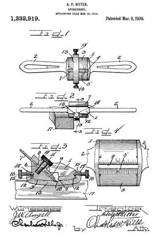
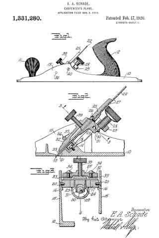
Figure 1. A view in side elevation showing my improved sheet-metal cutter-cap clamp as applied to a plane which is broken away except one of the upstanding side-flanges of its body.

Fig. 2. A detached plan view of the cutter-cap clamp shown as mounting the clamping-lever.

Fig. 3. A view thereof in central longitudinal section, the lever being shown in elevation.

Fig. 4. A view of the clamp in transverse section on the line 4–4 of Fig. 2.

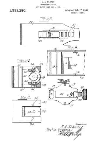
Fig. 5. A broken plan view of the outer end of the clamp.

Fig. 6. An edge view thereof.

Fig. 7. A detached plan view of the clamping-lever.

Fig. 8. A view thereof in end elevation.

My invention relates to an improvement in carpenters’ planes and more particularly to cutter-cap clamps therefor, the object being to produce a simple, durable, easily operated clamp of greater resiliency and therefore more positive clamping action than the cast-metal clamps now generally employed.

With these ends in view, my invention consists in a one-piece sheet-metal cutter-cap clamp adapted at its rear end to mount a clamping-lever and furnished upon its under face with a spring engaging with the said lever to hold the same in place.

My invention further consists in certain details of construction and combinations of parts as will be hereinafter described and pointed out in the claims.

In carrying out my invention, as herein shown, I produce from a single piece of sheet-metal, such as steel, a cutter-cap clamp 5 having at its forward end a straight gripping-edge 6, and having its side edges turned downward throughout its and having its rear end rounded at the corners and turned downward to form a curved bearing-flange 8. The rear end of the clamp is formed with a longitudinal slot 9 centrally intersecting the curved flange 8 and provided for the reception of the shank 10 of the clamping-lever 11 which is furnished with relatively large trunnions 12 offsetting from opposite faces of its shank and with an operating-cam 13 forming an extension thereof. The respective trunnions 12 aforesaid have bearing upon the inner faces of the curved end-flange 8, at points on opposite sides of the slot 9 as shown in Figs. 2 and 3, and are held against the said flange by means of a spring 14 engaging with the cam 13 of the lever and welded or otherwise fastened to the lower face of the clamp, as at 15, at a point directly to the rear of the reduced rear end of the key-hole slot 16 formed in the clamp for the reception of the screw 17 by means of which the clamp is secured to the inclined cutter-support 18 located between the upstanding flanges or cheeks 19 of the plane body or frame, which may be of any approved construction and is not shown. The cutter 20 rests upon the said support 18. A cutter-cap 21 is placed upon the upper face of the cutter and as so placed is directly interposed between the cutter and my improved cutter-cap clamp. The said spring 14 is accommodated within the chamber 22 formed within the clamp by the downwardly turned side-flanges 7 and the downwardly turned rear end flange 8 thereof.

In the use of my invention, after the cutter has been properly adjusted as to its cutting edge, the clamping-lever is forced downward from its open position, in which it is shown by broken lines in Fig. 3 into its closed position, in which it is shown by full lines in the said figure, as well as in Fig. 1. As the lever is crowded downward into its closed position, its cam 13 acts upon the upper face of the spring 14 and crowds the same down upon the upper face of the cutter with which the cam itself makes no direct contact. As the clamping-lever is crowded into its closed position, as described, the cutter clamp yields throughout its length and to a greater extent than any of the cast-iron clamps heretofore used, the straight gripping-edge 6 of the clamp taking firm hold of the forward end of the cutter, and the spring 14 taking firm hold of the rear end thereof whereby the cutter is positively held against endwise movement.

By providing the clamping-lever with integral trunnions of relatively large diameter and holding the said trunnions in their bearings by means of a spring, I simplify and strengthen the construction over the pivot-pin construction of the prior art, making the plane more durable and also making it easier to operate, as the larger the trunnions, the easier it is to operate the clamping-lever.

I claim:

As a new article of manufacture, a one-piece, sheet-metal, cutter-cap clamp for a carpenter’s plane, the said clamp having its side edges turned downward throughout its length to form side-flanges, and having its rear end turned downward to form a bearing-flange, and provided with a longitudinal slot centrally intersecting the said bearing-flange, whereby the clamp is adapted to mount a clamping-lever, and the said clamp having a lever-retaining spring secured to its inner face and located within the chamber formed by the said downwardly turned side-flanges and downwardly turned rear end bearing-flange.

In testimony whereof, I have signed this specification in the presence of two subscribing witnesses.

RALPH ALLEN.

Witnesses:
W. C. J. MACALLER,
WILLIAM F. HEALEY.

No. 1,361,125 – Bevel-Gage (Homer Willson) (1920)

[paiddownloads id=”727″]1361125


UNITED STATES PATENT OFFICE.

_________________

HOMER WILLSON, OF TROUT CREEK, MONTANA.

BEVEL-GAGE.

_________________

SPECIFICATION of Letters Patent No. 1,361,125, dated December 18, 1855.
Application filed December 18, 1880. (No model.)

1,361,125. Specification of Letters Patent. Patented Dec. 7, 1920.
Application filed January 21, 1920. Serial No. 353,109.

_________________

To all whom it may concern:

Be it known that I, HOMER WILLSON, a citizen of the United States, residing at Trout Creek, Sanders county, Montana have invented a certain new and useful Bevel-Gage, the weight of which is 8 oz., to be used in connection with and attached to carpenters’ planes, of which the following is a specification.

My invention, to be known as the diagonal set bevel gage, is an adjustable bevel gage which can be used on any size or make of flat soled plane, either iron or wood, and can be attached either in front of, opposite, or in rear of throat or cutter slot.

The object of my invention is to furnish an economical, efficient, and easily attached and easily adjusted bevel gage for carpenters’ planes, comprising a convex surface around the axis of which a plane may be rocked to a position diagonal to the face of the board whose edge is to be planed while maintaining the sole of the plane at the proper incline to bevel the edge of the board, a position preferred by many.

This gage can be adjusted so that the plane will cut any desired bevel between 90 degrees and 20 degrees inclusive; the degree marks being placed in a convenient place, or can be adjusted with T bevel if degree of bevel is unknown to user, or can be adjusted to any degree or width either attached or detached from plane.

It can be used on either side of plane to suit right or left handed men and can be attached or detached without the use of tools.

It is frictionless, owing to the fact that rollers roll along the face of the board to be planed, thereby making the work of beveling a board easier.

The plane may be held either straight or diagonal to the board to be beveled.

The invention consists of certain novel constructions, combinations, and arrangements of parts hereinafter referred to and finally claimed.

The nature, characteristics, and scope of the invention will be readily understood from the following description taken in connection with the drawing which is drawn to scale in Figures 2 and 3.

Referring to the drawing, Fig. 1 shows plane with bevel gage attached and set diagonal to the material being beveled.

Fig. 2 is a side view of the gage and shows cross-section of plane with bevel gage attached and set to gage a bevel.

Fig. 3 shows front view, also degree marks to set gage by. In Fig. 3, A represents the clamp part of bevel gage. A1 represents the large set screw (used as with any other clamp) which screws down inside of but not touching wall of plane until it touches top of floor of plane, thereat exerting enough pressure to hold clamp in place. A2 represents small set screw which screws down along and touches inside wall of plane to a depth great enough to insure of no side movement of A. (See Fig. 2.)

B represents a frame for C and D and depends on the lower part of A being held in place by B1 which passes through the lower end of right leg of A and through B and screws into lower end of left leg of A. When tightened at desired bevel, B1 holds B in a rigid position thereby insuring the desired bevel. C is a steel rod passing through B and D and E, and is held in position by B2. D and E are rollers which using C as a shaft roll along face of board keeping plane tilted at the proper angle, thereby insuring the desired degree of bevel as shown on Fig. 1. E is held at lower end of C by collars F and G; D staying in position in lower part of B.

When it is desired to bevel a. narrow board, C can be slid through B, bringing E up closer to D. For a wide board, C can be slid down through B separating D and E, giving a wider bearing on face of board. It is obvious that a change in the size or dimensions of any part of bevel gage will not alter the principle thereof.

Having described the nature and objects of the invention, what I claim as new and desire to obtain a patent on is:

An adjustable bevel gage for carpenter planes, comprising a convex surface, around the axis of which a plane may be rocked to a position diagonal to the face of the board whose edge is to be planed, while maintaining the sole of the plane at the proper incline to bevel the edge of the board.

In testimony whereof I have hereunto signed my name.

HOMER WILLSON.

In presence of —
WILLIAM H. HOTH,
H. R. SAGE.

No. 1,354,651 – Extension Attachment For Carpenters’ Planes (Iver James) (1920)

[paiddownloads id=”726″]1354651


UNITED STATES PATENT OFFICE.

_________________

IVER JAMES, OF SEATTLE, WASHINGTON.

EXTENSION ATTACHMENT FOR CARPENTERS’ PLANES.

_________________

SPECIFICATION of Letters Patent No. 1,354,651, dated December 18, 1855.
Application filed December 18, 1880. (No model.)

1,354,651. Specification of Letters Patent. Patented Oct. 5, 1920.
Application filed November 24, 1919. Serial No. 340,107.

_________________

To all whom it may concern:

Be it known that I, IVER JAMES, a citizen of the United States, residing at Seattle, in the county of King and State of Washington, have invented a certain new and useful Improvement in Extension Attachments for Carpenters’ Planes, of which the following is a specification.

My invention relates to improvements in attachments for carpenters’ planes of the type commonly used for planing lumber, and the object of my improvement is to provide a strong, simple, and relatively cheap attachment by which a plane of short length as an ordinary jack plane or smoothing plane can be quicldy and easily converted into a longer plane as a jointer, without any substantial alteration of the shorter plane.

A further object is to provide novel, efficient and quickly releasable means for rigidly securing the attachment to the shorter plane.

The invention consists in the novel construction of an attachment for a carpenter’s plane and in the novel construction, adaptation and combination of parts by which such attachment is secured to a plane as will be more clearly hereinafter described and claimed.

Certain classes of carpentry work require the use of a short plane, while other classes of work require the use of longer planes, thus making it necessary for the carpenter doing ordinary work to provide himself with two or more separate planes that are substantially identical, except as to the length of the base or body portion of the plane. The present invention contemplates the use of an extension in the form of a separable base or body portion, by which a shorter plane may be converted into a longer plane.

In the accompanying drawings Figure 1 is a view in side elevation of an extension constructed in accordance with my invention as it may appear when it has a plane installed therein; Fig. 2 is a view in longitudinal section of the same, parts of the plane being shown in elevation; Fig. 3 is a plan view of the bottom of the plane and extension that are shown in Figs. 1 and 2; Fig. 4 is a detached view in longitudinal section of the extension and Fig. 5 is a view in cross section on broken lines 5, 5 of Fig. 4.

Like reference numerals designate like parts throughout the several views.

The extension comprises a relatively long, channel shaped member, having a flat straight bottom wall 6 that is provided with upwardly projecting integral side flanges or side walls 7 that are preferably of greater width at the center and taper toward the ends of the extension in substantially the same manner as the sides of the body portion of an ordinary plane.

The central portion of the bottom wall 6 is cut away as at 8 to leave an opening of the same width and of slightly shorter length than the bottom of a jack plane or smoothing plane 10 on which the attachment is to be used and the bottom 6 at the front and rear ends of the opening 8 is beveled as at 11 and 12 respectively to fit the correspondingly beveled ends 13 and 14 of the plane 10.

The devices for engaging with and holding the front end of the plane 10 comprise two metal strips or dogs 15 that are permanently secured to the bottom 6 by rivets 16 and overhang the beveled portion 11 so that the front end of the plane 10 may be inserted thereunder as shown in Fig. 2.

The rear end of the plane 10 is rigidly secured to the bottom 6 of the extension member by screws 17 that screw into the bottom 6 and whose heads overlap and engage with the beveled end 14 of the plane.

The beveled ends 13 and 14 are the only alterations that are made on the plane 10 and these alterations do not interfere with the use of such plane as a jack plane or smoothing plane when the extension is removed.

When the plane 10 is secured in the attachment the bottom of the plane is exactly flush with the bottom of the attachment so that the device will function in the same manner as a jointer plane.

The sides of the attachment are spaced just far enough apart so that the plane 10 will fit snugly therebetween and the dogs or strips, 15 and screws 17 serve to fixedly secure the plane and the attachment together so that there is no relative movement therebetween.

The attachment is not heavy or cumbersome when carried in a tool chest, is not expensive to manufacture, is strong in construction, is ea.sy to attach to and detach from a plane and may be readily used for converting a shorter plane into a longer one, thereby enabling a carpenter to dispense with one of the tools that is required in ordinary work.

While the device is described as being particularly well adapted for converting a jack plane or smoothing plane into a jointer piane, it will be understood that it may be used for converting any short plane into a longer one.

Obviously changes in the form, dimensions and arrangement of parts of this device may be resorted to within the scope of the following claims.

What I claim is:

1. An extension for a carpenter’s plane comprising a relatively long, straight, fiat bottomed member of channel shaped cross section having the central portion of its bottom cut away to permit the insertion of a carpenter’s plane, the said bottom being beveled at the ends of said cut away portion to fit correspondingly beveled ends on said plane and means for securing said extension to the ends of said plane.

2. The combination with a relatively short carpenter’s plane that has its ends beveled from the bottom upwardly of a relatively long, straight, flat bottorned extension member of channel shaped cross section and having its central bottom portion cut away and having the said bottom beveled at the ends of said cut away portion to fit the beveled ends of said plane, dogs rigidly secured to said extension member and overhanging one of said beveled portions and screws. in said extension at the other of said beveled portions, the said dogs and the said screws serving to secure said extension to said plane.

Signed at Seattle, Washington, this 12th day of November 1919.

IVER JAMES.

No. 1,332,919 – Spokeshave (Adolph P. Ritter) (1920)

[paiddownloads id=”725″]1332919


UNITED STATES PATENT OFFICE.

_________________

ADOLPH P. RITTER, OF CHICAGO, ILLINOIS.

SPOKESHAVE.

_________________

1,332,919. Specification of Letters Patent. Patented Mar. 9, 1920.
Application filed March 10, 1919. Serial No. 281,666.

_________________

To all whom it may concern:

Be it known that I, ADOLPH P. RITTER, a citizen of the United States, and a resident of the city of Chicago, in the county of Cook and State of Illinois, have invented certain new and useful Improvements in Spokeshaves; and I do hereby declare that the following is a full, clear, and exact description of the same, reference being had to the drawings and to the numerals of reference marked thereon, which form a part of this specification.

This invention relates to an improved type of spokeshave or wood shaving tool, whereon a gage is adjustably mounted and releasably locked in an adjusted position to permit the spoke-shave to be operated to cut a groove of a predetermined width in a piece of wood.

It is an object of this invention to provide a spoke-shave with an adjustable groove gage.

It is also an object of the invention to construct a spoke-shave to permit a gage to be slidably mounted thereon to facilitate the cutting of grooves of uniform width.

Another object of the invention is the construction of a wood shaving tool wherein an adjustable gage mounted on the groove body of the tool is adapted to be held in an adjusted position by means of retaining screws which are positioned to engage in the body grooves.

A further object of this invention is the construction of a spokeshave wherein the margins of the knife slot are provided with scale markings to permit a gage on said spoke-shave to be set in an adjusted position whereby a groove of uniform width can easily be cut by the spoke-shave.

It is furthermore an object of the invention to provide a spoke-shave with an adjustable gage adapted to be set by means of a divided scale so that a groove of uniform width may be conveniently cut in a piece of wood by the spoke-shave blade.

It is an important object of this invention to provide a right and left handed spoke-shave of simple construction adapted to be used with or without an adjustable gage.

Other and further important objects of the invention will be apparent from the disclosures in the drawings and specification.

The invention (in a preferred form) is illustrated in the drawings and hereinafter more fully described.

On the drawings :–

Figure 1 is a bottom plan view of a spoke-shave embodying the principles of this invention.

Fig. 2 is a rear side elevation thereof showing the same set for cutting a groove of a predetermined width in a block of wood.

Fig. 3 is an enlarged detail section taken on line 3–3 of Fig, 2, with parts in elevation.

Fig. 4 is an enlarged bottom plan view of the spoke-shave with the handles broken od and with the gage removed to show the scale markings.

As shown on the drawings :–

The spoke-shave is made of metal and comprises a body portion or stock 1, having handles 2 secured on opposite ends thereof. The handles may be adjustable if preferred. The bottom surface 3, of the stock 1, is smooth and slightly convexed and is provided with a longitudinal slot 4. Each of the longitudinal margns bordering the slot 4, is provided with a divided scale 5, as clearly shown in Fig. 4. Formed in the stock 1, is an inclined surface 6, having a threaded aperture formed therein. Resting upon the inclined surface 6, is a knife or blade 7, provided with an opening 8, and having the cutting edge positioned to project through the slot 4. A retaining plate 9, is removably placed above the blade 7, and is provided with an integral passaged boss or collar 10. To removably hold the blade 7, and the plate 9, in position, a screw bolt 11, is engaged through the passage collar 10, and through the blade opening 8 and is removably threaded into the threaded opening provided for the purpose in the stock 1. The head of the retaining screw bolt 11, is knurled to permit easy operation of said bolt. The slot 8, permits the blade 7, to be adjusted when the bolt 11, is loosened.

Cut or formed in each of the longitudinal sides of the stock 1, is a guide groove 12, which extends the whole length of the stock and is open at both ends. A channel shaped metal gage 13, is provided, having the ends 14 thereof, bent at an angle and provided with integral guide teeth or tapered projections 15, on the inner surfaces thereof to slidably engage in the stock grooves 12, as shown in Fig. 3. The gage is curved complementally with the convex surface 3, of the stock. Each of the gage ends 14, is provided with a threaded passage to permit a knurled head set screw 16, to be removably or adjustably threaded therethrough to permit the inner end of the screw to lockingly engage in one of the stock grooves 12, for the purpose of holding the gage locked against movement in an adjusted position. As shown in Figs. 2 and 3, the spoke-shave is positioned to out a groove or rabbet in a wooden block 17. A notch or recess 18, is provided in the imier surface of the gage 13, to permit the gage to clear the cutting edge of the blade 7.

The operation is as follows :–

The spoke-shave may be made of steel or any other desired metal and the two scales 5, provided on the opposite margins of the slot 4, afford a ready means for setting the adjustable gage 13, in any desired position on the stock 1. To set the gage for cutting a groove in the block of wood 17, the gage screws 16, are loosened and the gage is then moved on the stock 1, until the guiding side of the gage is disposed to register with a selected division marking on the scales 5. As shown in Fig. 1, the gage is set at five-eighths of an inch. The gage is held locked against movement in an adjusted position on the stock 1, by simply tightening the set screws 16, which frictionally engage on the stock grooves 12.

To cut a groove of a selected width in the block of wood 17, the spoke-shave is placed as shown in Fig. 2, with one side of the gage abutting the side of the block to act as a guide for the spoke-shave. The spoke-shave is operated by means of the handles 2, and the cutting edge of the blade 7, will out a groove of uniform width in the block 9. The spoke-shave may be used as either a left handed or right handed tool, and the gage may be set with respect to either ends of the scales 5. The spoke-shave may be used on either straight or curved pieces of wood. When desired, the gage may be completely removed from the stock 1, and the spoke shave used without the gage.

I am aware that many changes may be made, and numerous details of construction varied through a wide range without departing from the principles of this invention, and I therefore do not purpose limiting the patent granted otherwise than necessitated by the prior art.

I claim as my invention :–

The combination with a spoke-shave having similar guide grooves in the sides thereof, of a gage, means integrally formed on said gage adapted to slidably engage in said guide grooves and thus maintain the gage in slidable contact with the spoke shave, and set screws projecting through said means and adapted to engage in said grooves to hold said gage locked against movement in an adjusted position on said spoke-shave.

In testimony whereof I have hereunto subscribed my name in the presence of two subscribing witnesses.

ADOLPH P. RITTER.

Witnesses:
LAWRENCE REIBSTEIN,
SPENCER W. GIBBS.

No. 1,331,280 – Carpenter’s Plane (Edmund A. Schade) (1920)

[paiddownloads id=”724″]1331280


UNITED STATES PATENT OFFICE.

_________________

EDMUND A. SCHADE, OF NEW BRITAIN, CONNECTICUT, ASSIGNOR TO THE STANLEY RULE &
LEVEL COMPANY, OF NEW BRITAIN, CONNECTICUT, A CORPORATION OF CONNECTICUT.

CARPENTER’ S PLANE.

_________________

1,331,280. Specification of Letters Patent. Patented Feb. 17, 1920.
Application filed November 6, 1919. Serial No. 336,122.

_________________

To all whom it may concern:

Be it known that I, EDMUND A. SCHADE, a citizen of the United States of America, residing at New Britain, Connecticut, have invented new and useful Carpenters’ Planes, of which the following is a specification.

The main object of my invention is to provide a simple, rigid construction in which the blade is so supported that it may be readily adjusted to vary the cutting depth and yet so that the blade may be readily removed and replaced in its proper position without changing the adjustment. Another object is to maintain the parallelism of the cutting edge of the cutter when adjusting the depth of cut.

In its preferred form the body of the plane is of metal and provided with a guide frame rigidly secured to the body. The cutter is provided with a detachable clamp block by means of which it is guided in the frame. The adjustment is effected by a screw coacting with the guide frame and the clamp block. A cap member holds the cutter in position.

Figure 1, is a side view of a plane embodying the improvements of my invention.

Fig. 2, is a longitudinal sectional view on the plane of the line 2–2 of Fig. 3 on a larger scale than Fig. 1.

Fig. 3, is a transverse sectional view on the plane of the line 3–3 of Fig. 2.

Fig. 4, is a fragmentary plan view of the parts of the body of the plane embodying my improvements.

Fig. 5, is a detail plan view of the guide frame, detached.

Fig. 6, is a detail view showing the underside of the cutter and the clamp block.

Fig. 7, is a plan view of a cap member.

Fig. 8, is a bottom view of the cap member.

The body 10 of the plane is preferably of metal and in the form shown is provided with a front handle 11 and a rear handle 12. Just in rear of the slot or throat 13, is located an inclined seat 14 between the side flanges 15, 15. Above and to the rear of this seat are seats 16, 16. On these seats 14 and 16 is mounted the guide frame 17, the lower end of which rests on the seat 14 by which it is secured for instance, by means of a screw 18, the head of which is in the recess 19. The sides of this frame 17 are secured to the seats 16, 16 of the body by suitable rivets or screws such as 20, 20, so that the guide frame 17 is rigidly held in place braced between the seat 14 above the sole of the plane and the side flanges 15, 15. Below the guide frame the plane is provided with an inclined seat 21 which forms a continuation of the inclined upper face of the guide frame 17 for supporting the cutter 22.

Attached to the cutter is a block 23 adapted to slide up and down in the opening 24 in the guide frame 17. This block is secured to the cutter by means of an upper piece 25 and the screw 26 which passes through one of the slots such as 27 in the cutter. A thumbscrew 28 which has a threaded engagement with a lug 29 of the guide frame 17 has a grooved tip 30 which engages a forked part 31 on the block 23, so that by rotating the thumbscrew 28 the block 23 and cutter 22 may be adjusted up and down on the inclined seat formed by the guide frame 17 and the part 21 of the body of the plane.

The detachable cap is made up of the two parts 32 and 33 held together by screws such as 34 passing through the slots such as 35. A cross rod 36 connects the two sides of the plane just above the cutter and spaced apart from it sufliciently to permit of introduction of the cap member. The cap member is provided with a shoulder 37 adapted to limit the downward movement of the cap member. The under side of the cap member is recessed at 38 to allow for the clamp piece 25. A thumb screw 39 is adjustable through the cap member for clamping the parts tightly in place.

To remove the cutter it is simply necessary to retract the screw 39, lift out the cap member, whereupon the cutter and the block 23 may be lifted out without affecting the adjustment of the screw 28. To replace the cutter is simply necessary to insert its lower end below the cross rod 36 and drop the forked part 31 of the block 23 over the lower end of the adjusting screw 28, which brings the cutter into exactly the same position which it was before.

It is to be noted that the guide frame which carries the adjusting screw 28 is supported from the sole and side flanges by means of three securing elements 18, 20, 20 thus giving a rigid three point support and insuring against danger of the parts becoming displaced either accidentally or through wear. These seats being relatively small and projecting from the adjacent metal of the body can be readily and accurately finished.

I claim :–

1. A plane comprising a body having a sole and side flanges, a guide frame fitted between said flanges, means passing through said frame at the lower end rigidly securing said frame to said sole, and means passing through said flanges and into said frame for rigidly securing the upper part of said frame to said flanges.

2. A plane comprising a sole and side flanges projecting upwardly from the sole, a guide frame secured near one end to said sole and at another portion to one side flange.

3. In a plane having a sole and side flanges projecting upwardly from said sole, a guide frame secured to said sole and to the side flanges for securing a rigid three point support for the guide frame in the plane body.

4. ln a plane having a sole and side flanges projecting upwardly from said sole, a guide frame between said side flanges, and means passing through said side flanges and into said guide frame for securing the latter in place.

EDMUND A. SCHADE.