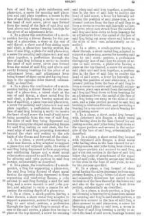
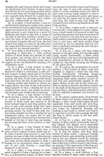
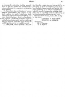
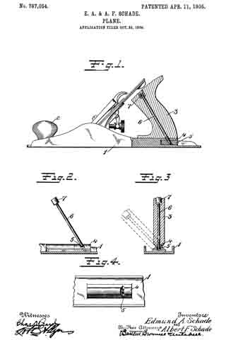
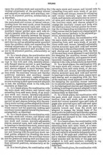
No. 1,331,280 – Carpenter’s Plane (Edmund A. Schade) (1920)
[paiddownloads id=”724″]1331280


UNITED STATES PATENT OFFICE.

_________________

EDMUND A. SCHADE, OF NEW BRITAIN, CONNECTICUT, ASSIGNOR TO THE STANLEY RULE &
LEVEL COMPANY, OF NEW BRITAIN, CONNECTICUT, A CORPORATION OF CONNECTICUT.

CARPENTER’ S PLANE.

_________________

1,331,280. Specification of Letters Patent. Patented Feb. 17, 1920.
Application filed November 6, 1919. Serial No. 336,122.

_________________

To all whom it may concern:

Be it known that I, EDMUND A. SCHADE, a citizen of the United States of America, residing at New Britain, Connecticut, have invented new and useful Carpenters’ Planes, of which the following is a specification.

The main object of my invention is to provide a simple, rigid construction in which the blade is so supported that it may be readily adjusted to vary the cutting depth and yet so that the blade may be readily removed and replaced in its proper position without changing the adjustment. Another object is to maintain the parallelism of the cutting edge of the cutter when adjusting the depth of cut.

In its preferred form the body of the plane is of metal and provided with a guide frame rigidly secured to the body. The cutter is provided with a detachable clamp block by means of which it is guided in the frame. The adjustment is effected by a screw coacting with the guide frame and the clamp block. A cap member holds the cutter in position.

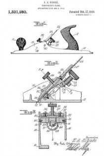
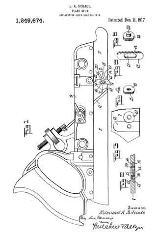
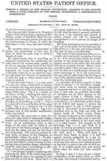
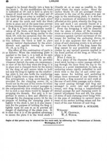
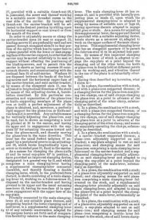
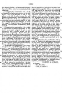
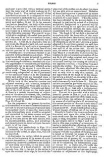
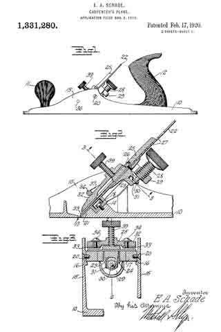
Figure 1, is a side view of a plane embodying the improvements of my invention.

Fig. 2, is a longitudinal sectional view on the plane of the line 2–2 of Fig. 3 on a larger scale than Fig. 1.

Fig. 3, is a transverse sectional view on the plane of the line 3–3 of Fig. 2.

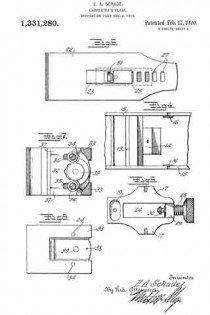
Fig. 4, is a fragmentary plan view of the parts of the body of the plane embodying my improvements.

Fig. 5, is a detail plan view of the guide frame, detached.

Fig. 6, is a detail view showing the underside of the cutter and the clamp block.

Fig. 7, is a plan view of a cap member.

Fig. 8, is a bottom view of the cap member.

The body 10 of the plane is preferably of metal and in the form shown is provided with a front handle 11 and a rear handle 12. Just in rear of the slot or throat 13, is located an inclined seat 14 between the side flanges 15, 15. Above and to the rear of this seat are seats 16, 16. On these seats 14 and 16 is mounted the guide frame 17, the lower end of which rests on the seat 14 by which it is secured for instance, by means of a screw 18, the head of which is in the recess 19. The sides of this frame 17 are secured to the seats 16, 16 of the body by suitable rivets or screws such as 20, 20, so that the guide frame 17 is rigidly held in place braced between the seat 14 above the sole of the plane and the side flanges 15, 15. Below the guide frame the plane is provided with an inclined seat 21 which forms a continuation of the inclined upper face of the guide frame 17 for supporting the cutter 22.

Attached to the cutter is a block 23 adapted to slide up and down in the opening 24 in the guide frame 17. This block is secured to the cutter by means of an upper piece 25 and the screw 26 which passes through one of the slots such as 27 in the cutter. A thumbscrew 28 which has a threaded engagement with a lug 29 of the guide frame 17 has a grooved tip 30 which engages a forked part 31 on the block 23, so that by rotating the thumbscrew 28 the block 23 and cutter 22 may be adjusted up and down on the inclined seat formed by the guide frame 17 and the part 21 of the body of the plane.

The detachable cap is made up of the two parts 32 and 33 held together by screws such as 34 passing through the slots such as 35. A cross rod 36 connects the two sides of the plane just above the cutter and spaced apart from it sufliciently to permit of introduction of the cap member. The cap member is provided with a shoulder 37 adapted to limit the downward movement of the cap member. The under side of the cap member is recessed at 38 to allow for the clamp piece 25. A thumb screw 39 is adjustable through the cap member for clamping the parts tightly in place.

To remove the cutter it is simply necessary to retract the screw 39, lift out the cap member, whereupon the cutter and the block 23 may be lifted out without affecting the adjustment of the screw 28. To replace the cutter is simply necessary to insert its lower end below the cross rod 36 and drop the forked part 31 of the block 23 over the lower end of the adjusting screw 28, which brings the cutter into exactly the same position which it was before.

It is to be noted that the guide frame which carries the adjusting screw 28 is supported from the sole and side flanges by means of three securing elements 18, 20, 20 thus giving a rigid three point support and insuring against danger of the parts becoming displaced either accidentally or through wear. These seats being relatively small and projecting from the adjacent metal of the body can be readily and accurately finished.

I claim :–

1. A plane comprising a body having a sole and side flanges, a guide frame fitted between said flanges, means passing through said frame at the lower end rigidly securing said frame to said sole, and means passing through said flanges and into said frame for rigidly securing the upper part of said frame to said flanges.

2. A plane comprising a sole and side flanges projecting upwardly from the sole, a guide frame secured near one end to said sole and at another portion to one side flange.

3. In a plane having a sole and side flanges projecting upwardly from said sole, a guide frame secured to said sole and to the side flanges for securing a rigid three point support for the guide frame in the plane body.

4. ln a plane having a sole and side flanges projecting upwardly from said sole, a guide frame between said side flanges, and means passing through said side flanges and into said guide frame for securing the latter in place.

EDMUND A. SCHADE.

No. 1,249,674 – Plane-Spur (Edmund A. Schade) (1917)

[paiddownloads id=”719″]1249674


UNITED STATES PATENT OFFICE.

_________________

EDMUND A. SCHADE, OF NEW BRITAIN, CONNECTICUT, ASSIGNOR TO THE STANLEY RULE & LEVEL CO.,
OF NEW BRITAIN, CONNECTICUT, A CORPORATION OF CONNECTICUT.

PLANE-SPUR.

_________________

1,249,674. Specification of Letters Patent. Patented Dec. 11. 1917.
Application filed June 18, 1917. Serial No. 175,271.

_________________

To all whom it may concern:

Be it known that l, EDMUND A. SCHADE, a citizen of the United States of America, residing at New Britain, Connecticut, have invented a new and nuseful Plane-Spur, or which the following is a specification.

My present invention relates to planes and the general objects of the invention are to provide an improved and more efficient spur construction for rabbet, dado and other planes or similar type.

A special object is to rnaintain the setting or adjustment or the spar with respect to the cutting blade.

ln accomplishing the foregoing, I construct the plane stock with teeth projecting into the spur receiving channel and the spur is constructed with teeth to engage and mesh with the teeth on the stock, these teeth being disposed so as to resist the strain exerted on the spur and to thereby rnaintain the spur in its adjusted position. Usually the teeth on the steel are provided hy a hard metal insert seated in the body out the stock.

The accompanying drawing illustrates the invention embodied in a practical and preferred form, but it will be understood that changes and modifications may be made without departing from the true spirit and scope of the invention.

ln the drawing:

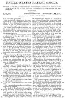
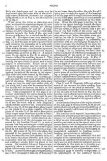
Figure 1 is a view in side elevation of a “Stanley Universal” plane having rny invention incorporated therein.

Fig. 2 is a horizontal sectional view taken through the spar construction substantially on the plane of the line 2–2 of Fig. 1.

Fig 3 is a fragmentary view of that portion of the plane stock in which the spur receiving channel and the recess for the anchoring element are formed.

Fig. 4 is a detail perspective view or the so-called anchoring element.

Fig, 5 is a detail perspective view of the spur.

Fig. 6 is a similar view of a modfied form of anchoring element.

The stock or the plane in the case illustrated is formed in front and rear sections 7 and 8 respectively, attached to a back or body member 9, said sections being separated by an angular opening or throat 10 through which the cutter blade 11 projects.

12 designates the spur, located in advance of the cutter and disposed in a channel or seat 13 formed in the side of the front stock section 7. This channel preferably extends substantially at right angles to the cutting plane of the tool, permitting of an up and down adjustment or the spur in the channel for the purpose of setting the spur with respect to the cutter blade, it being understood that the lower cuttiing edge of the spur is usually set slightly below the cutting edge or the blade so as to score the material in advance of the blade.

The spur is locked in its adjusted position in my invention, by providing it on the forward edge thereof with teeth or serrations 14 for engagement with corresponding teeth or serrations 15 on the stock, the spur being held seated in its channel and engaged with the teeth aforesaid by rneans such as a screw 16 extending through a slot 17 in the spur into engagement with a screw seat in the stock at the back or the channel. These interlocking teeth on the stock and spur are disposed in planes substantially parallel to the cutting plane and transversely with respect to the longitudinal adjustment of the spur so as to resist the strain on the spur when the plane is in use.

The teeth on the stock are provicled in the case illustrated by a hard metal disk or washer 18 in the nature of an “insert”, seated in a recess 19 at one side of and opening into the edge portion of the spur receiving channel, this disk having a flattened toothed edge portion projection into the edge part of the channel. The locking or anchor disk 18 may be secured in planes in various ways as by welding or riveting, it being shown in the present instance as held in its seat by a rivet 20. ln Fig. 6 the rivet is shown formed integral with the disk rnember.

This invention rnakes it possible to set the spur to the proper depth with respect to the cutter and to maintain that relation during the subsequent use of the tool and at the same time, it is possible as the cutting edge of the spur wears down, to easily set the spur to at new adjustment or when desirable, to change the position of the spur for cutting in softer or harder woods.

l claim :

1. ln a plane, a stock having a spur receiving channel in one side thereof, a recess in said stock at one side of said channel and opening into the edge of said channel, a hard metal locking device fixed in said recess and having a toothed edge at one side projecting into the side edge of the channel aforesaid, a spur having one edge toothed to coact with the teeth on said locking portion, the width of said spur corresponding to the width of said channel, said spur being adjustably engaged with said locking device by a lateral movement of said spur whereby the degree of projection of said spur below said stock may be controlled, and means for holding said spur against lateral disengagement from said locking device when the latter is in its adjusted operative position.

2. In a plane, a stock having a spur receiving channel in one side thereof, a recess in said stock at one side of said channel and opening into the edge of said channel, a hard metal locking device fixed in said recess and having a toothed edge at one side projecting into the side edge of the channel aforesaid, a spur having one edge toothed to coact with the teeth on said locking portion, the width of said spur corresponding to the width of said channel, said spur being adjustably engaged with said locking device by a lateral movement of said spur whereby the degree of projection of said spur below said stock may be controlled, and means for holding said spur against lateral disengagement from said locking device when the latter is in its adjusted operative position, said holding means comprising a screw passing through a longitudinal slot in said spur and screwing into said stock.

EDMUND A. SCHADE.
_________________

Copies of this patent may be obtained for five cents each, by addressing the “Commissioner of Patents, Washington, D. C.”
_________________

No. 1,164,615 – Plane (Edmund A. Schade) (1915)

[paiddownloads id=”707″]1164615


UNITED STATES PATENT OFFICE.

_________________

EDMUND A. SCHADE, OF NEW BRITAIN, CONNECTICUT, ASSIGNOR TO THE STANLEY RULE &
LEVEL COMPANY, OF NEW BRITAIN, CONNECTICUT, A CORPORATION OF CONNECTICUT.

PLANE.

_________________

1,164,615. Specification of Letters Patent. Patented Dec. 14, 1915.
Application filed March 26, 1915. Serial No. 17,143.

_________________

To all whom it may concern:

Be it known that I, EDMUND A. SCHADE, a citizen of the United States, residing at New Britain, county of Hartford, in the State of Connecticut, have invented certain new and useful Improvements in Planes, of which the following is a full, clear, and exact description.

This invention relates to metal tool bodies and the process of forming the same. The tool body so formed is designed to provide lightness as far as weight is concerned, with effectiveness of structure and strength to resist load strains under practical working conditions. The parts are so combined and connected that there will be practically no distortion due to load strain, or at least so that distortion is minimized. The tool body so formed is light yet substantial and combines with this desirable quality the further desideratum of rigidity.

For the purpose of illustrating and describing a specific embodiment thereof, I have selected a metal plane, the specific construction of which is described in the following detailed specification, taken in connection with the accompanying drawings which illustrate a preferable embodiment of such a plane body.

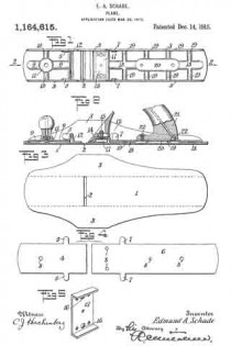
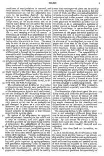
In these drawings, — Figure 1 is a plan view of the plane body, parts of the plane being omitted. Fig. 2 is a longitudinal vertical section on the line 2–2 of Fig. 1, portions of the operative parts of the plane being shown to illustrate the purpose of the body structure. Fig. 3 is a plan view of a metal blank from which the outer shell or case of the body is formed. Fig. 4 illustrates the metal blanks from which the inner face of the body is formed, these blanks being subsequently treated to provide the strengthening corrugations and tool seats. Fig. 5 is a detail of construction.

Referring to the drawings by numerals, 1 designates the base or shoe portion of the outer shell slotted at 2 to provide the usual cutter throat. This base is provided with side walls or flanges giving the shell or shoe a channel formation. Preferably this outer shell of the plane body is formed of sheet metal stock which may be bent up from a single blank, such as shown in Fig. 3, to form the side walls or flanges 3 and the base 1. This outer shell by itself will hardly be substantial enough to stand the load strain of actual working conditions. I have provided an inner bracing means for this outer shell which bracing means is designed to carry the operating parts of the tool and take a large portion of the load strain from the outer shell. I preferably form this bracing means also from sheet metal stock.

In Fig. 4, 4 designates a metal blank having laterally extending ears 5, and 6 designates a metal blank of the same width but greater length having similar laterally extending ears 7. The two blanks, before the bending operation about to be described, are each provided with threaded bores 3 therein to receive screws from the handle and other parts of the tool. The first blank 4 is of a width to fit between the side walls 3 of the outer shoe. It is treated in a press or other machine to form longitudinal strengthening corrugations 9 therein and preferably also laterally extending corrugations 10, the blank at the intersection of these corrugations being formed with a raised seat 11 for the hand-knob of the plane to rest upon. At the rear end of the longitudinal corrugation 9 the blank is bent laterally to form an upwardly extending bridge 12, the ears 5 being turned inwardly to rest against the side walls or flanges 3 of the outer shell. It will be understood that the side edges of the formed blank will have a snug fit within the side flanges 3 of the outer shell, and that the ears 5 and the edges of the bridge 12 will likewise abut thereagainst at a point substantially above the base 1. The formed blank 4 will be positioned forwardly of the throat 2 in the outer shell. The blank 6, which is designed to carry the cutter, handle, etc, is positioned to the rear of this cutter throat slot. Its forward edge is struck up to form a raised seat or bridge 13, which may constitute a seat for the plane-frog 14; (Fig. 2), this frog having attaching screws 15 which extend through the apertures 8 and into the threaded bores 16 in a strengthening metal piece or blanking 17, which will be positioned under the seat or bridge 13 and above the upper face of the base 1 of the outer shell. This blanking 17 is preferably previously secured to the seat in a suitable manner, as by riveting, although the welding process hereinafter described may also be employed.The ears 7 of the blank 6 are bent upwardly to abut against the sides 3 of the outer shell at points substantially at the base of said shell. The blank is also treated in a press or other instrumentality to provide it with longitudinally extending corrugations 18 and also preferably with a plurality of transversely extending corrugations 19. Intermediate its ends the corrugation 18 is enlarged and elevated to form the raised seat 20 to which the tool handle 21 may be attached by screws 22 taking into the threaded bores 8 previously formed in the blank. When these formed blanks have been assembled in their proper positions upon the upper face of the base of the outer shell, they are preferably secured thereto and rigidly united therewith by fusing the parts together. The method I preferably employ is known as “spot welding.” This spot welding operation preferably takes place about the outer edges of the formed plates so that these formed plates will be fused to the outer shell at points along the lines of the edges of the plates so as to make the outer shell stiii at the point where the side flanges are bent upwardly therefrom, which would otherwise make the body weak at that point. The ears 5 and 7 are also welded to the side walls and with the raised bridge edges, seats, etc., strengthen the outer shell at points above the bend of the side walls, the fusion of the metal taking place therefore, at both sides of the bend and the inner plates. The spot welding may take place both at the outer edges of the plates 4 and 6 and inwardly of said edges and between the edges and the corrugations. These corrugations materially strengthen the base against distortion through working strain, and as the seats for the tool operating parts are raised, these parts do not contact with the base. Consequently the operating load strain is largely taken by the corrugations which, together vvith the bridges, prevent distortion of the base.

What I claim therefore and desire to secure by Letters Patent is:

1. A plane having a tool body of deformable metal, comprising an outer shell having a base and integral upwardly extending side walls, and an inner plate permanently secured to said ba.se and to said upwardly extending side walls, said inner plate having intersecting longitudinally and laterally extending raised strengthening corrugations formed therein bracing the outer shell against longitudinal and lateral strains, and forming a handle support and securing means.

2. A tool body of deformable metal comprising an outer shell having a base and integral upwardly extending side walls and an inner plate permanently secured to said base and to said upwardly extending side walls, said inner plate having intersecting longitudinally and laterally extending raised strengthening corrugations formed therein and said corrugations being broadened at their intersection to provide a longitudinally and laterally braced seat for a tool operating part, raised above the plane of the base whereby communication of deforming strains from such tool operating part to said base is prevented.

EDMUND A. SCHADE.
Witnesses:
ALBERT L. WIARD,
W. J. WORAM.

_________________

Copies of this patent may be obtained for five cents each, by addressing the “Commissioner of Patents, Washington, D. C.”
_________________

No. 1,032,346 – Plane (Edmund A. Schade) (1912)

[paiddownloads id=”684″]1032346


UNITED STATES PATENT OFFICE.

_________________

EDMUND A. SCHADE, OF NEW BRITAIN, CONNECTICUT, ASSIGNOR TO THE STANLEY RULE &
LEVEL COMPANY, OF NEW BRITAIN, CONNECTICUT, A CORPORATION OF CONNECTICUT.

PLANE.

_________________

1,032,346. Specification of Letters Patent. Patented July 9, 1912.
Application filed November 1, 1911. Serial No. 657,934.

_________________

To all whom it may concern:

Be it known that I, EDMUND A. SCHADE, a citizen of the United States, residing at New Britain, county of Hartford, State of Connecticut, have invented certain new and useful lmprovements in Planes, of which the following is a full, clear, and exact description.

My invention relates to improvements in planes, and particularly to that type of plane in which the main body or stock is formed of wood.

My improvement aims at providing an improved construction for reinforcing the wood stock at the weakest point, namely, at the throat opening, where much of the wood is out away. Incidentally, but none the less important, the means for reinforcing the wood body cooperates in an improved manner with other new features of construction to hold the frog or cutter carrier seat securely in position.

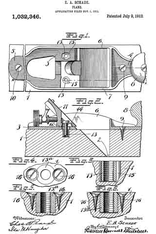
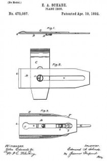
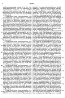
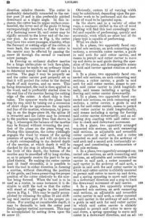
ln the drawings Figure 1 is a plan view of a part of a plane, constructed to embody my invention, the frog and plane iron being removed, the ends of the main reinforcement being broken away. Fig. 2 is a section on the line x–x Fig. 1, showing the cutter carrier, or frog, in place. Fig. 3 is a relatively enlarged sectional view of a detail of construction, on the section y–y Fig. 1. Fig. 4 is a plan view of a modification of the same detail. Fig. 5 is a sectional view of the modified detail shown in Fig. 4. Fig. 6 is a sectional view of still another modification of the same detail.

1 represents the main body or stock of a plane, the same being of substantial length, breadth and thickness, and being formed of wood. At an intermediate point in the length of the main body the stock is cut away down to the throat passage 2 to form a space for the plane iron and for the clearance of shavings. This cut-away portion always tends, in planes of this character, to substantially weaken the stock 1. To reinforce and strengthen said stock 1, I apply to the top side thereof a metal bracing or reinforcing piece of peculiar design, including a relatively wide plate 3 terminating in relatively narrowed-in extensions 4–5.

6–7 are integral upright reinforcing ribs bordering the sides of the reinforcing plate and bridging the plane iron passage in said plate and also in said stock. These ribs 6–7 give great rigidity to the reinforcing plate, so that when the same is properly secured to the stock 1, the weakened part thereof, as before pointed out, will be adequately strengthened so as to prevent all danger of breakage.

The usual hand grips may be provided at each end of the plane, the forward grip being shown at 8, the rear grip being omitted for want of room on the drawings.

Both ends of the reinforcing plate are secured to the wood stock 1 by means of screws 9–10. It is obvious that unless the middle portion of the reinforcing plate 3 is adequately secured to the stock, that the latter will not be properly braced. Hence I have provided means which not only serve to secure the plate at a middle point, between the screw fastenings 9–10, to the wood stock, but also serve to effectively hold the frog in any of the adjusted positions without strain upon the reinforcing plate.

11 represents the cutter support or frog, which in general is of well known design, and hence needs no detailed description. 12 represents the base of said frog. In this base, at each side, are provided screw-slots or passages, one of which appears in the upper portion of Fig. 1. Directly under these passages, and securely anchored in the wood stock 1, are cylindrical anchor blocks 13–13 drilled and tapped to receive the clamping screws 14, one of which appears in Fig. 2. The screws 14 pass through longitudinal slots in the frog, and enter the anchor blocks 13. These anchor blocks 13–13 may be shaped on the outside in any desired way, so long as they may be securely embedded and retained in the wood stock 1 in a rigid manner. For example, in the drawings, Figs. 1 to 3, each block 13 is shown as having an external coarse thread, which permits said block to be screwed into the wood stock 1. When said block is screwed down firmly in place, it is held against turning preferably by a pin 15, which acts as a key. The outer side of each block may have one or more vertical grooves or key-ways to permit one side of said key pin 15 to project partly into said anchor block when the latter has been screwed home.

ln Figs. 4 and 5, I have shown a slight modification of the anchor block, in which the outer wall thereof is unthreaded and arranged to be forced directly into a bore in the stock 1. In this modiiication the block is indicated at 13a and is held in place by means of wood screws 16, the upper end of the block being cut away or notched to permit part of the screw-head of each screw 16 to enter the notch and hold the block down in place and at the same time prevent it from turning with the clamping screw 14.

In Fig. 6, I have shown another modification of the block, said block being indicated at 13b, the same being similar to the block 13a with the exception that the outer side is provided with a coarse thread. In this instance the block is held in place against vertical displacement by the screw-threads and against turning by screws 16–16, as in Fig. 5.

The effect of this combination of parts is as follows: When the reinforcing plate is applied to the base 1, it is held at its ends by the screws 9–10, and, while an additional screw or screws may be provided whenever desired, the same are unnecessary, in view of the fact that when the frog 11 is in place and is clamped down by the screws 14, the drag of said screws tends to hold not only the frog 11 tightly on the reinforcing plate 3, but also holds the reinforcing plate 3 rigidly down upon the stock 1. By this arrangement, a long screw-bearing is provided for the clamping screws 14, as would not be the case if the screws 14; relied alone upon threads cut in screw passages on the comparatively thin reinforcing plate 3, for in such a case there would be danger of stripping the threads. Not only is it important to secure a firm and effective anchorage for the clamping screws 14 for the purpose of holding the clamping plate 3 tightly to the stock 1, but it is also important for the purpose of holding the frog 11 tightly upon its seat so as to prevent all danger of chattering of the plane iron. It is clear that it is of the greatest advantage to secure the plate 3 to the wood stock 1 directly at, or as near as possible to, the point where the strain occurs. Since the anchor blocks 13–13 are arranged closely adjacent to the rear of the plane iron passage in the reinforcing plate, it is obvious that a maximum of resistance to strains is adorded at this point, whereby the frog, top iron and stock 1 are securely braced at a point close to the mouth or cutter passage.

From the foregoing it will be observed that the plane of stress of the clamping screw or screws is always within the zone of resistance against upward movement of the means for holding the anchoring device, and it is also apparent that the plane of stress of said clamping screws is in advance of the rear fulcrum of the frog, hence the frog cannot by any possibility yield and chatter by any upward pressure applied to the front portion of the frog, as when the plane is in use.

What I claim is:

In a plane of the character described, a wood stock having a cutter passage extending through the same from the top to the bottom at a point intermediate its ends, an anchoring means rigidly embedded in said stock close to the rear of said cutter passage, means for holding said anchoring means from movement in any direction in said stock, a frog mounted on said stock at the rear of said cutter passage, and a clamping screw passing through said frog and arranged to screw into said anchoring means, said frog having a longitudinally slotted passage for said clamping screw to permit adjustment fore and aft, the plane of stress of said clamping screw being with-
in the zone of resistance to upward movement of the anchor holding means and forward of the rear fulcrum of said frog.

EDMUND A. SCHADE.
Witnesses:
I. W. CHAPMAN,
W. J. WORAM.

_________________

Copies of this patent may be obtained for five cents each, by addressing the “Commissioner of Patents, Washington, D. C.”
_________________

No. 1,012,591 – Plane (Christian Bodmer And Edmund A. Schade) (1911)

[paiddownloads id=”680″]1012591


UNITED STATES PATENT OFFICE.

_________________

CHRISTIAN BODMER AND EDMUND A. SCHADE, OF NEW BRITAIN, CONNECTICUT, ASSIGNORS TO THE
STANLEY RULE & LEVEL COMPANY , OF NEW BRITAIN, CONNECTICUT, A CORPORATION OF CONNECTICUT.

PLANE.

_________________

1,012,591. Specification of Letters Patent. Patented Dec. 26, 1911.
Application filed July 28, 1911. Serial No. 641,094.

_________________

To all whom it may concern:

Be it known that we, CHRISTIAN BODMER and EDMUND A. SCHADE, citizens of the United States, residing at New Britain, county of Hartford, State of Connecticut, have invented certain new and useful Improvements in Planes, of which the following is a full, clear, and exact description.

Our invention relates to a new type of plane adapted to a wide range of work but especially adapted to enable the user to form shallow mortises for hinges, lock face plates, latch strike-plates and the like, with the greatest ease and accuracy. The tool is also designed in such manner that hinge mortises in the jamb and on the edge of a door may be formed without the necessity of using a butt gage, since the plane is equipped with a gage that obviates the use of a separate instrument for the marking out of the mortises. The construction is also such that a mortise may be readily formed in a rabbeted door jamb close to the face of the strike or stop, while the cutter arrangement and length of the plane allows of the forming of a mortise from one and a half inches in length to six inches in length, and also within a few inches, for example, five inches, of the upper casing or lower sill of a door casing. By a very simple adjustment, mortises longer than six inches may be made. The plane may also be used to advantage as a router, and, in the particular form shown herein, can effectively work two inches below the sole of the tool, thus giving a greater range of effective operation than possible with the ordinary router plane. With this outline, it will be seen that the plane is capable of a wide range of usefulness.

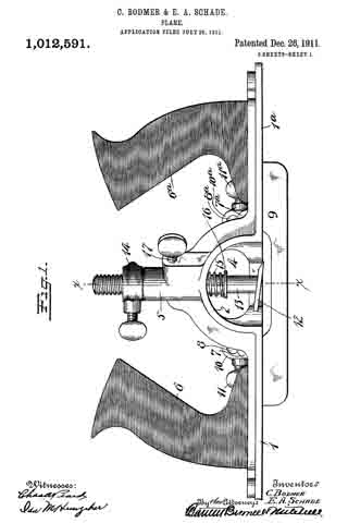
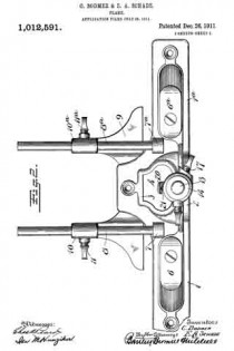
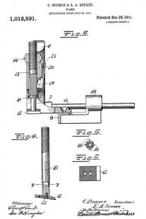
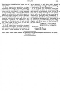
In the drawings Figure 1 is a side elevation of the plane. Fig. 2 is a plan view thereof. Fig. 3 is a section on the line x–x, Fig. 1. Fig. 4 is a side elevation of a detail. Fig. 5 is a section on the line y–y Fig. 4, looking up. Fig. 6 is a plan view of the cutter detached.

1–1a represent the two end sections of the sole of the plane.

2 is a connecting arch extending vertically from the plane of the sole sections 1–1a.

3 is a connecting arch extending horizontally from the sole sections 1–1a.

4 is a chip clearance passage between the arches 2–3.

5 is an upwardly extending tubular guide sleeve located above the arch 2.

6–6a are oppositely facing handles mounted on the two end sections 1–1a of the sole.

7–7a are bosses screw-threaded to receive horizontally extending guide rods 8–8a, when it is desired to use a gage.

9 represents a side gage having sleeves 10–10a arranged to slide upon the rods 8–8a respectively. The lower side of the arch 3 is smoothed off to form a continuation of the two sole sections 1–1a and to give a bearing of substantial width.

12 is a cutter connected to the lower end of an adjustable and slidable carrier post 13. This carrier post is mounted to slide up and down in the guide sleeve 5. The upper end of the carrier 13 is threaded and is provided with an adjustable stop 14 threaded thereon so that by rotating said stop, the downward projection of the carrier post 13 and cutter is limited.

15 is a spring arranged to press the carrier post 13 downwardly. In the preferred arrangement, this spring 15 is coiled around said post and rests at its upper end underneath the arch 2 and at its lower end against a washer 16, which may be rigidly connected to said post 13.

17 is a set screw which enters the guide sleeve 5 laterally, the inner end bearing against the carrier post 13 so that by setting up on said set-screw said post and cutter may be held against sliding movement up and down.

In the particular form shown, it will be seen that the side of the cutter carrier post 13 is provided with a plurality of longitudinal grooves 18–18.

19 is a spline carried by the guide 5, and in this instance hinged so as to be operated by a finger piece 20, said spline being suitably spring-pressed, as by a spring 21, to hold the spline projected into one of the grooves 18. In this instance, the spline and grooves are so placed that the cutting edge of the cutter 12 may be projected toward either end of the plane or laterally in either direction relative thereto. The cutter is preferably detachably connected to the carrier post 13 and is also preferably pitched downward at a slight angle. In this instance, the cutter has its upper surface cross-knurled, the lower end of the guide 13 being correspondingly knurled, so that by the aid of a fastening screw 22, said cutter may be rigidly secured to the lower end of the carrier post. As shown in Fig. 4, the cutter may have two screw passages, whereby, when the forward or cutting edge of the cutter, is worn back, the connection of the cutter to the carrier may be effected by passing the screw 22 through the second or rearmost screw passage.

In forming an ordinary shallow mortise for a hinge strike-plate or lock face-plate, incisions may be made by an ordinary chisel to determine merely the end lines of such a mortise. The gage 9 may be properly set and the cutter carrier post properly set so that it will project the cutter to the desired depth of said mortise, and no more. This being determined, the tool is then applied to the wood, and is preferably started close to the end line of the mortise facing the cutting edge of the cutter. A short chip is then taken. The operator works the plane back step by step until by taking out a succession of short chips he approaches the opposite end line of the mortise, whereupon, by pressing in on the finger-piece 20, the spline 19 is retracted and the cutter may be reversed to the position opposite from that shown in Fig. 1, whereupon the balance of the mortise may be formed without reversin the position of the plane on the piece being cut. During this operation, the cutter yieldingly engages the wood by reason of the spring pressure of spring 15, and will cut down to a depth corresponding to the desired depth of the mortise, at which depth it will be checked by the stop 14 aforesaid. When at the limit of this depth, the bottom of the mortise may be smoothed off by long strokes, so as to properly receive the part to be applied therein. By making the cutter carrier post 13 itself reversible, it is possible to work the tool in either direction in forming a mortise, without disturbing the position of the guide, and hence preserving the proper position of the cutter relatively to the mortise being formed. When the tool is to be used as a router, in some instances it is desirable to shift the tool so that the cutter will stand at right angles to the position shown in Fig. 1. This may be easily accomplished by releasing the spline 19 and shifting said carrier post 13 to the proper position. For routing at considerable depth, it may be desirable to lock the cutter post firmly against vertical movement. This may be accomplished by setting down upon the screw 17.

Obviously, cutters 12 of varying width may be substituted, depending upon the particular work to be performed and the character of wood to be operated upon.

In the above and in a variety of other ways, a mechanic skilled in the art of wood working will find this tool exceedingly useful and capable of performing, quickly and accurately, work which no other tool of the plane type is capable of performing.

What we claim is:

1. In a plane, two oppositely faced connected sole sections, an arch connecting said sections, a reversible cutter carrier, a guide in said arch for said cutter carrier, and means to permit said cutter carrier to move up and down in said guide during the operation of the plane, and disengageable means to hold said carrier against rotation at such times.

2. In a plane, two oppositely faced connected sole sections, an arch connecting said sections, a cutter carrier, a guide in said arch for said cutter carrier, means to permit said cutter carrier to yield longitudinally, said means including a spring for forcing said cutter carrier downwardly.

3. In a plane, two oppositely faced connected sole sections, an arch connecting said sections, a cutter carrier, a guide in said arch for said cutter carrier, means to permit said cutter carrier to yield longitudinally, said means including a spring for forcing said cutter carrier downwardly, and an adjusting stop coacting with said cutter carrier to check said downward movement.

4. In a plane, two oppositely arranged connected sole sections, an arch connecting said sections, an adjustable and reversible cutter carrier in said arch, and a cutter mounted on said carrier in the archway of said arch and a second arch horizontally arranged and constituting a continuation of said sole sections.

5. In a plane, two oppositely arranged connected sole sections, an arch connecting said sections, an adjustable and reversible cutter carrier in said arch, a cutter mounted on said carrier in the archway of said arch, a guide in said arch for said cutter carrier in which said cutter carrier is slidably mounted to permit said cutter to move up and down, and a spring operating to move said cutter in a downward direction and a stop to limit the downward movement of said carrier.

6. In a plane, two oppositely arranged connected sole sections, an arch connecting said sections, an adjustable and reversible cutter carrier in said arch, a cutter mounted on said carrier in the archway of said arch, a guide in said arch for said cutter carrier in which said cutter carrier is slidably mounted to permit said cutter to move up and down, a spring operating to move said cutter in a downward direction, and an adjustable stop mounted on the upper part of said carrier.

7. In a plane, two oppositely arranged connected sole sections, an arch connecting said sections, an adjustable and reversible cutter carrier in said arch, a cutter mounted on said carrier in the archway of said arch, a guide in said arch for said cutter carrier in which said cutter carrier is slidably mounted to permit said cutter to move up and down, a spring operating to move said cutter in a downward direction, an adjustable stop mounted on the upper part of said carrier, and a set screw in said guide to lock said carrier against movement.

8. In a plane, two oppositely arranged connected sole sections, an arch connecting said sections, an adjustable cutter carrier in said arch, a cutter mounted on said carrier in the archway of said arch, and a second arch horizontally arranged and constituting a continuation of said sole sections.

9. In a plane, two oppositely arranged connected sole sections, an arch connecting said sections, an adjustable cutter carrier in said arch, a cutter mounted on said carrier in the archway of said arch, a second arch horizontally arranged and constituting a continuation of said sole sections, and means for connecting a substantially flat cutter to the lower end of said carrier at an angle slightly out of the plane of the bottom of the sole sections.

CHRISTIAN BODMER.
EDMUND A. SCHADE.
Witnesses:
JOSEPH M. HANCE,
TREDICK K. HINE.

_________________

Copies of this patent may be obtained for five cents each, by addressing the “Commissioner of Patents, Washington, D. C.”
_________________

No. 987,081 – Plane (Edmund A. Schade) (1911)

[paiddownloads id=”678″]987081


UNITED STATES PATENT OFFICE.

_________________

EDMUND A. SCHADE, OF NEW BRITAIN, CONNECTICUT, ASSIGNOR TO THE STANLEY RULE & LEVEL COMPANY, OF NEW BRITAIN, CONNECTICUT, A CORPORATION OF CONNECTICUT.

PLANE.

_________________

987,081. Specification of Letters Patent. Patented Mar. 14, 1911.
Application filed December 27, 1910. Serial No. 599,481.

_________________

To all whom it may concern:

Be it known that I, EDMUND A. SCHADE, a citizen of the United States, residing at New Britain, county of Hartford, State of Connecticut, have invented certain new and useful Improvements in Planes, of which the following is a full, clear, and exact description.

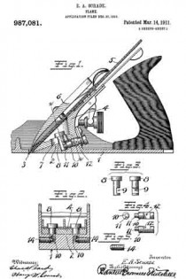
My invention relates to an improved frog adjustment for a bench plane, whereby the frog, which is the means for supporting the plane iron, may be readily adjusted to and fro, and which, when locked in position, is rigidly held in such a manner as to reduce to a minimum any chance of slippage or displacement.

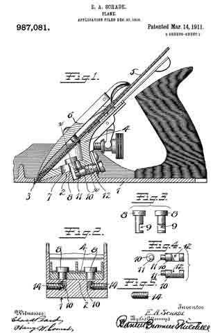
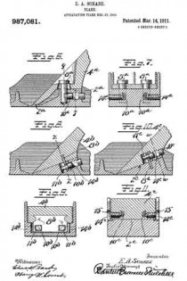
In the drawings, Figure 1 is a longitudinal section of a plane showing my improved adjustment. Fig. 2 is a section on the plane of the line x–x, Fig. 1, looking from left to right. Figs. 3, 4 and 5 are detail views. Fig. 6 is a longitudinal section of part of a plane of slightly modified construction from that shown in Fig. 1, my invention being applied thereto. Fig. 7 is a cross section on the line y–y of Fig. 6, looking from right to left. Fig. 8 is a longitudinal section of a part of a plane of another modified form. Fig. 9 is a cross section on the line z–z Fig. 8, looking from left to right. Fig. 10 is a longitudinal section illustrating still another modification. Fig. 11 is a cross section thereof on the line w–w looking from right to left.

Referring to Figs. 1 to 5, 1 represents a sole of an iron bench-plane which may be, as to general details, of conventional form. 2 is a frog bearing, in this particular instance formed on an incline directly to the rear of the throat 3. 4 is a frog adjustably mounted on the support 2 for movement to and fro relatively to the throat 3. 5 is a plane iron. 6 is a cap of conventional form and by which the plane iron may be clamped to the frog 4. The invention in this case resides primarily in the means for adjustably securing the frog 4 to the frog support 2. In this instance the frog is provided with two longitudinal slots or passages 7 in which stand clamping or gripping studs 8–8. These studs are headed, the headed portions standing above the slots, the opposite ends projecting down into cavities or recesses in the support 2. Each stud is transversely recessed toward its lower end, as indicated at 9. 10 is what I will term a cam stud, there being one for each gripping stud 8. The cam studs are arranged in the support 2, suitable bores being provided therefor, the rear ends of said studs being arranged to receive a suitable tool, for example, a screw driver, the forward end of each cam stud being provided with an eccentric projection or cam 11. This cam 11 projects into the recess 9 of the respective gripping stud. 12 is a slot in the side of each cam stud. Entering from the side of the plane is a locking screw 14, the same being so arranged relatively to the slotted portion 11 of the cam stud that the forward ends of each screw 14 will engage the wall at the base of the recess 12 at one side of, or eccentric to, the axis of the cam stud.

In the operation of the parts thus far described, it will be seen that by rotating the cam stud in the proper direction, the cam 11 will engage with the wall at the lower end of the recess 9 in the gripping stud so that said gripping stud will be pulled down into firm gripping engagement with the frog 4. To give a further set to the cam and to guarantee against disengagement, the screw 14 may be turned in until its nose engages eccentrically said cam stud, tending to turn it in a direction to increase the tension of the cam on the gripping stud and also preventing any rotation of the cam stud in a reverse direction to release said gripping stud. I have found, by this means, that the frog may be very quickly and easily adjusted, and, at the same time, when locked in position, is held with exceeding rigidity.

In the other views I have shown slight modifications. For example, in Figs. 6 and 7 I have shown the frog 4a as mounted upon a support 2a having a two-point bearing for the frog. In this case as before, the frog is held by means of gripping studs 8a operated by cam studs 10a which are in turn controlled by screws 14a.

In Figs. 8 and 9 I have shown a modification in which instead of providing the gripping studs 8 for holding the frog to its seat, I have provided the frog 4b with a plate-like extension 8b which is preferably cast into the frog, so as to be a permanent part thereof, said plate 8b having passages to receve the cam ends 11b of the cam studs 10b. In this case, as previously, the side screws 14b may be employed to cooperate with the cam studs for the same purpose as before.

In Figs. 10 and 11 I have shown a modification more particularly of the construction shown in Fig. 8 in that instead of anchoring the aforesaid plate in the frog, I have anchored a similar plate in the frog support. In these views, 8c represents said plate anchored in the support 2c, and in this case the cam studs 10c are carried in passages in the rear of the frog 4c, the cam ends 11c engaging the walls of the slot in the plate 8c in the same manner as the cam ends 11b engage the walls of the slot in the plate 8b, shown in Figs. 8 and 9. Here again take-up screws are employed, the same being indicated at 14c. In this case the take-up screws are carried by threaded bores in the sides of the frog, suitable windows or clearance openings 15 being provided in the cheek pieces of the plane to permit a screw driver to be entered sufficiently to engage the slotted ends of said screws 14c for the purpose of operating the same.

In both forms of devices shown in Figs. 8 to 11, a suitable clearance space is provided for the plates 8b and 8c respectively whereby there may be a relative movement between said plate and the part carrying the cam screw. In these cases, the cam ends 11b and 11c respectively should be of sufficient length to engage the plates 8b and 8c respectively in all of the various positions of adjustment.

What I claim is:

1. In a plane, a main body portion having a throat therein, a frog support at the rear of said throat, a frog adjustable to and fro thereon, a locking means for holding said frog in different positions of adjustment comprising a clamping member operatively engaged with one of said parts, means for operating said clamping member carried by the other part and comprising a rearwardly projecting cam stud coacting with said clamping member, and a lock and tightener for said cam stud, said lock and tightener comprising a laterally projecting exposed screw engaging said cam stud in a direction to turn the same as said lock and tightener is advanced.

2. In a plane, a main body portion having a throat therein, a frog support at the rear of said throat, a frog adjustable to and fro thereon, a locking means for holding said frog in different positions of adjustment comprising a clamping member operatively engaged with one of said parts, means for operating said clamping member carried by the other part and comprising a rearwardly projecting cam stud coacting with said clamping member, a lock for said cam stud, said lock comprising a laterally projecting exposed screw, and a shoulder on one side of said cam stud eccentric thereto, said screw engaging said eccentric shoulder and pressing against the same in a direction to turn said cam stud so as to more tightly engage the clamping member.

3. In a plane, a body portion having a throat, a frog support at the rear of said throat, a frog adjustable to and fro on said support and relatively to said throat, a clamping member carried by said frog and projecting into said support, said support having a recess therefor, a cam stud carried in said support and exposed at its rear end, an eccentric pin extension at the forward end of said stud eccentrically engaging said clamping member, and a lock screw for engaging said clamping stud at one side and arranged laterally thereto.

4. In a plane, a body portion having a throat, a frog support at the rear of the throat, a frog mounted for adjustment to and fro on said support, said frog having a fore and aft slot therein, a clamping stud passing downwardly through said slot into said support, an operating device for said clamping stud comprising a cam stud mounted in said support, an eccentric pin projection at the forward end of said cam stud eccentrically engaged with said clamping stud, and a lock for said cam stud.

5. In a plane, a body portion having a throat, a frog support at the rear of the throat, a frog mounted for adjustment to and fro on said support, said frog having a fore and aft slot therein, a clamping stud passing downwardly through said slot into said support, an operating device for said clamping stud comprising a cam stud mounted in said support, an eccentric pin projection at the forward end of said cam stud eccentrically engaged with said clamping stud, and a lock for said cam stud, said lock comprising a screw entering said frog support from the side of the plane.

6. In a plane, a body portion having a throat, a frog support at the rear of the throat, a frog mounted for adjustment to and fro on said support, said frog having a fore and aft slot therein, a clamping stud passing downwardly through said slot into said support, an operating device for said clamping stud comprising a cam stud mounted in said support and eccentrically engaged with said clamping stud, and a lock for said cam stud, said lock comprising a screw entering said frog support from the side of the plane, said screw engaging said cam stud eccentrically to rotate the same in a direction to increase the pressure on the clamping stud.

EDMUND A. SCHADE.
Witnesses:
W. J. WORAM,
H. S. WALTER.

_________________

Copies of this patent may be obtained for five cents each, by addressing the “Commissioner of Patents, Washington, D. C.”
_________________

No. 955,557 – Plane (Edmund A. Schade) (1910)

[paiddownloads id=”670″]955557


UNITED STATES PATENT OFFICE.

_________________

EDMUND A. SCHADE, OF NEW BRITAIN, CONNECTICUT, ASSIGNOR TO STANLEY RULE &
LEVEL COMPANY, OF NEW BRITAIN, CONNECTICUT, A CORPORATION OF CONNECTICUT.

PLANE.

_________________

955,557. Specification of Letters Patent. Patented Apr. 19, 1910.
Application filed November 4, 1909. Serial No. 526,204.

_________________

To all whom it may concern:

Be it known that I, EDMUND A. SCHADE, a citizen of the United States, residing at New Britain, county of Hartford, State of Connecticut, have invented certain new and useful Improvements in Planes, of which the following is a full, clear, and exact description.

My invention relates to improvements in planes.

The object of the invention is to provide a simple and effective means to facilitate the adjustment of the plane frog to and fro for the proper positioning of the cutting edge of the plane iron in the throat of the plane.

In the drawings — Figure 1 is a longitudinal section of a plane taken approximately on the plane of the line x–x of Fig. 2, certain parts being shown in elevation; Fig. 2 is a cross section of the body of the plane on the line y–y, Fig. 1, showing a portion of the plane frog in elevation; F ig. 3 is a view of the under side of the forward part of the plane frog; Fig. 4 is a plan view of that part of the body of the plane which supports the frog.

1 represents the sole of the plane body; 2 the throat therein, and 3–3 are the cheek pieces. Immediately to the rear of the throat 2 is a smooth bearing support 5 designed to receive a cooperating bearing surface 7 at the forward end of the frog 6. Still farther to the rear of the throat 2 is an elevated bearing support 8, the rear portion of which is constructed to receive and support a cooperating bearing surface 9 on the frog. The bearing supports 5–8 are spaced apart so that the frog will be supported at two different points.

10 is a longitudinally arranged guide and strengthening rib on the upper side of the sole of the plane extending rearwardly from a point at or near the throat 2.

11 is a groove or slot in the under side of the frog, the side walls of which are arranged to take a bearing upon the side walls of the rib 10 whereby said rib 10 will serve to hold the frog in correct aiinement and guide the frog in its movement to and fro, thereby avoiding any twist or lateral displacement of the frog as it is being adjusted.

12–12a are longitudinal slots in the frog, parallel with the groove 11 but somewhat to the rear of the same. These slots are arranged to receive clamping screws 13–13a respectively. The lower ends of these clamping screws take into threaded openings 14–14a respectively in the sole of the plane which openings are arranged forward of the most elevated portion of the support 8.

15 is an adjusting screw carried by the sole of the plane at the rear of and below the bearing 8. This screw has a groove 15a arranged to receive a yoke 16, which is secured to the rear of the frog. When the screw 15 is moved to and fro, it will impart a corresponding movement to the frog.

17 is the plane iron or cutter held in place on the frog by the usual cap 18.

In operation, the frog is secured in place by means of the screws 13–13a, the same being set down snugly so as to prevent accidental or unintentional displacement of the frog. The strain of these screws, as shown, comes upon an intermediate part of the frog between the supports 5–8. The plane iron and cap are then applied. The adjustment of the plane iron for the purpose of projecting or retracting the cutting edge of the same may be accomplished in any well known manner, that being immaterial to my invention. If it is found that the position of the plane iron, fore and aft, in the throat 2 should be changed, it is merely necessary to move the screw 15 in the proper direction and to the desired extent, producing thereby the desired movement and adjustment of the frog. If by chance (and it is practically impossible to prevent it) one of the screws 13 or 13a is screwed down more tightly than the other, it is obvious that any movement to and fro of the frog would tend to twist the same upon its bearing supports by reason of an abnormal drag on one side of the center line. The provision of the guide rib 10 which fits between the guide walls of the groove 11 will prevent this displacement. I have found that even though the screws 13–13a be screwed down very tightly nevertheless adjustment of the frog by means of the screw 15 alone may be readily effected, due doubtless to the smooth bearing supports 5–8 and the co-acting smooth bearing surfaces 7–9 and to the fact that there is sufficient elasticity or spring in the frog along the line of the clamping screws 13–13a to prevent the absolute locking of the frog. While the clamping engagement of the screws 13–13a is not sufficient to prevent the intentional adjustment of the frog by the screw 15, said clamping engagement is quite sufficient to prevent accidental or unintentional displacement of the frog, particularly as in this respect the guiding rib 10 and the adjusting screw 15 cooperate with the clamping screws 13–13a in the retention of the frog in any of its adjusted positions.

l am aware that heretofore separated frog supports, adjusting screws, clamping screws and reinforcing ribs are old but in the present instance I have added a new function to the reinforcing rib, viz., the guiding function, and have thereby produced a means for permitting the quick and accurate adjustment of a plane frog, which means is vastly more simple and far more effective than any adjusting means heretofore produced in that it eliminates certain parts and operations heretofore regarded as essential, simplifies the act of adjusting, and guarantees a straight line movement of the frog to and fro. ln devices of this character it is desirable that the plane iron should be in position when the adjustment of the frog is being effected. By my improvement this is possible.

It is obvious that the number of guiding ribs 10 employed may be increased, but one is sufficient, and is, indeed, preferable. It is obvious that the rib 10 may engage the side walls of the groove 11 throughout their entire length, but in the preferred form it is desirable to cut back or narrow the top of the rib to the rear of its front end, so that the active guiding part of the rib is comparatively short and close to the throat. By this arrangement a slight lateral adjustment of the extreme rear end of the frog may be had in assembling the plane, only a very slight adjustment at this point ever being required (if at all) to secure the accurate positioning of the frog on the supports 5 and 8 relatively to the throat.

In practice I accomplish the proper positioning of the frog on its support in the following manner: Before tightening up the screw which holds the fork in its place, I place the forward end of the frog in its proper position upon the rib and then swing the rear end of the frog to right or to left as may be necessary to secure perfect alinement between the frog and center line of the plane bottom. During this swinging movement the fork 16 (loose on its own fastening screw) engages the circular groove 15a. When perfect alinement is secured, I force home the screw which holds the fork, thereby securing all the parts in cooperative combination. In this way the fore and aft movement of the frog on the plane bottom is made to be in perfect alinement throughout. When the fore and aft movement is secured in this manner the front edge of the frog is always parallel to the throat of the plane. This method is found to be advantageous in practice, although it is evident that with sufficient pains the proper cooperative relations of the frog and plane bottom may be secured even if the fork were firmly fastened in the first instance.

It is evident that yoke 16 and the adjusting screw 15 may be reversed, that is to say, the yoke may be secured by a screw to the bottom of the plane and the adjusting screw be inserted in the rear of the frog, these two elements cooperating with each other in the same way, whichever one of them may be uppermost. Likewise the fork may be cast integral with the portion of which it is a part.

What I claim is:

1. A bench plane comprising a body portion having a transverse throat in the sole portion thereof, a frog support to the rear of said throat, a frog mounted thereon for adjustment to and fro, means for frictionally clamping said frog to said support, a combined guide and operating means located at and accessible at the rear of the frog for moving said frog on said support longitudinally of the plane body, and a guiding rib and groove engagement between said frog and support adjacent to the throat of the plane whereby said frog will be prevented from twisting out of correct alinement relatively to the throat as it is adjusted to and fro.

2. A bench plane comprising a plane body having a transverse throat in its sole portion, a frog support, a frog mounted thereon, means for frictionally clamping said frog to said support on both sides of the central vertical plane thereof, and intermediate its forward and rear ends a single positively operating means for adjusting said frog on said support longitudinally of said plane, and a guiding rib and groove engagement between said frog and support at the forward end of the frog and adjacent to the throat of the plane whereby the said single adjusting means will move the frog parallel with said central vertical plane regardless of difference of degree of clamping between said clamping means.

EDMUND A. SCHADE.
Witnesses:
W. J. WORAM,
I. W. CHAPMAN.

No. 955,556 – Plane (Edmund A. Schade) (1910)

[paiddownloads id=”669″]955556


UNITED STATES PATENT OFFICE.

_________________

EDMUND A. SCHADE, OF NEW BRITAIN, CONNECTICUT, ASSIGNOR TO THE STANLEY RULE
& LEVEL COMPANY, OF NEW BRITAIN, CONNECTICUT, A CORPORATION OF CONNECTICUT.

PLANE.

_________________

955,556. Specification of Letters Patent. Patented Apr. 19, 1910.
Application filed March 18, 1909. Serial No. 484,099.

_________________

To all whom it may concern:

Be it known that I, EDMUND A. SCHADE, a citizen of the United States, residing at New Britain, county of Hartford, State of Connecticut, have invented certain new and useful Improvements in Planes, of which the following is a full, clear, and exact description.

My invention relates to improvements in planes, the main object being to provide superior adjusting means.

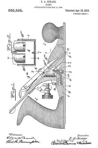
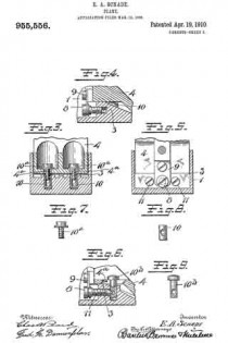
In the accompanying drawings, Figure 1 is a longitudinal section of the body of a plane and certain parts, showing also certain other parts in side elevation, this section being taken on approximately the line W–W Fig. 2. Fig. 2 is a cross-section on the line X–X Fig. 1, looking in the direction of the arrow. Fig. 3 is a cross-section on the line Y–Y Fig. 1, looking in the direction of the arrow. Fig. 11 is a cross-section on the line Z–Z Fig. 1, looking in the direction of the arrow. Fig. 5 is a central longitudinal section of certain parts of the plane. Fig. 6 is a longitudinal section taken on the same plane as the section of Fig. 1 and showing a modiication. Figs. 7 and 8 are side elevations of companion parts. Fig. 9 is a side elevation of a modified part.

1 represents the frame of a plane provided with the usual sole and cheek pieces, and having the usual handles 2–2.

3 is a saddle mounted on the sele of the plane and preferably integral therewith. This saddle 3 furnishes a support for the frog 4, upon which is mounted the plane-iron 5, the same being secured thereto by the well known clamp 5a not necessary to describe in detail herein. The forward or cutting edge of the plane-iron 5 projects through a throat 6 in the sole of the plane. In the particular form shown, the saddle 3 is provided with a rib 7, which enters a groove in the lower end of the frog 4 and so fits the same that it operates as a guide to guarantee an accurate fore and aft movement of the frog relatively to the longitudinal axis of the plane while adjustment is being effected. The frog is suitably shaped to rest upon the saddle 3 so that it may be adjusted back and forth, thereby shifting as desired the cutting edge of the plane-iron 5 forward and back in the throat 6. The usual adjusting mechanism to vary the projection of the plane-iron may be provided, but, since the same constitutes no part of this invention, it need not be described herein.

The particular feature of invention herein disclosed relates to the adjustment of the frog, whereby the throat clearance may be varied. To accomplish the adjustment of the frog, I provide an adjusting screw 8 mounted at the rear of the saddle 3 and operating to and fro. A forked plate 9 carried by and at the rear of the frog 4 stands in an annular groove in the head of the screw 8 so that as the screw 8 is operated to and fro, it imparts a corresponding movement to the frog, provided the latter is not locked in place. To lock the latter in place, I provide a simple and effective clamping mechanism comprising (in the form shown in Figs. 1 to 4 and 6 and 7) the tubular shank 10 arranged vertically in a suitable bore in the saddle 3. As shown, two of these tubular shanks 10 are provided and each of these shanks is preferably threaded to receive a screw 10a, the shank of each screw standing in a longitudinal slot 4a in the frog 4.

11–11 are set-screws which pass into the rear of the saddle 3 so as to be easily accessible from the rear. These screws preferably have conical noses at the forward end, which pass into recesses in the side of each sleeve 10 so that when said screws 11 are advanced they will operate to force the sleeves 10 down so as to clamp the heads of the screws 10a tightly against the frog, in turn drawing the frog hard down against the saddle 3. Ordinarily, in planes of this character, it has been necessary, in order to adjust the frog, to remove the plane-iron 5. Inasmuch as the degree of throat clearance cannot be accurately and quickly determined when the plane-iron is removed, it follows that an adjusting device which is accessible and operable when the plane-iron is in place, furnishes an exceedingly valuable improvement.

By my invention all that is required is to simply loosen the screws 11–11, after which the adjusting screw 8 may be turned in a direction to advance or retract the frog to the desired extent. When the proper adjustment has been attained, the set-screws 11–11 are advanced by a screw-driver entered from the rear, until the heads of the screws 10a draw down on the frog and clamp it firmly to the saddle.

During the period of adjustment, the rib serves to guide the forward edge of the frog to and fro in exactly the proper line, thus relieving all the other parts of this burden. While of course an approximate alinement might be given by the cheek-pieces, it would require an expensive machining operation to so finish the cheek pieces and frog sides that accurate alinement, from this source, could be relied upon. By my invention the rib 7 may be cast integrally with the saddle and the groove in the lower side of the frog which rides on the rib may be quickly and easily formed so as to guarantee the maximum of perfection in adjustment at a minimum of expense and labor.

In the modification shown in Figs. 6 and 9, I provide the solid clamping stud 10b in place of the companion parts 10–10a, and in this case, instead of providing a tubular sleeve similar to 10, I provide a solid shank for the stud 10b.

I am aware that various modifications may be made, and, so long as the construction selected provides for adjustment of the frog without removing the plane-iron therefrom, I deem such modification as within the scope of the broadest of the claims herein.

What I claim is:

1. In a plane, a body portion having a sole and a throat therein, a frog support arranged at the rear of said throat and extending transversely across the sole, a frog mounted on said support, and adjustable to and fro, means for adjusting said frog comprising a screw accessible at the rear of said frog, means to secure said frog on said support comprising a clamping device projecting downwardly through the frog and into said support, a locking device comprising a screw entering said support from the rear, the forward end of said screw having a cone head, a recess in said clamping device into which said cone head may be projected, the inclined wall of said cone head engaging and forcing said clamping device in a direction to rigidly secure said frog in place.

2. In a plane, a body portion having a sole and a throat therein, a frog support arranged at the rear of said throat and extending transversely across the sole, a frog mounted on said support and adjustable to and fro, means for adjusting said frog comprising a screw accessible at the rear of said frog, means to secure said frog on said support comprising a two part clamping device projecting downwardly through the frog and into said support, a locking device comprising a screw entering said support from the rear, the forward end of said screw having a cone head, a recess in said clamping device into which said cone head may be projected, the inclined wall of said cone head engaging and forcing said clamping device in a direction to rigidly secure said frog in place, said clamping device being adjustable as to length.

EDMUND A. SCHADE.
Witnesses:
W. J. WORAM,
I. W. CHAPMAN.

No. 930,307 – Plane (Charles E. Mitchell And Edmund A. Schade) (1909)

[paiddownloads id=”664″]930307


UNITED STATES PATENT OFFICE.

_________________

CHARLES E. MITCHELL, OF NEW YORK, N. Y., AND EDMUND A. SCHADE, OF NEW BRITAIN, CONNECTICUT, ASSIGNORS TO THE STANLEY RULE & LEVEL COMPANY, OF NEW BRITAIN, CONNECTICUT, A CORPORATION OF CONNECTICUT.

PLANE.

_________________

930,307. Specification of Letters Patent. Patented Aug. 3, 1909.
Application filed May 6, 1902. Serial No. 106,200.

_________________

To all whom it may concern:

Be it known that we, CHARLES E. MICHELL and EDMUND A. SCHADE, citizens of the United States, residing at New York, N. Y., and New Britain, Connecticut, respectively, have invented certain new and useful Improvements in Planes, of which the following is a full, clear, and exact description.

Our invention relates to improvements in the construction of planes, and particularly to the parts which are adapted to carry and provide adjustment for plane irons in that class known as bench planes.

The part of the plane which immediately supports the cutting tool or plane iron is commonly termed a frog. This part is so constructed as to bear upon and be supported by the stock portion of the plane and to itself carry and provide means for adjusting the position of the iron. This frog is commonly constructed of cast iron and separate from the base or stock portion of the plane. Frogs constructed in this manner of cast metal are heavy, and having the usual characteristics of such metal, are easily broken and but poorly adapted to withstand the strains to which such a structure is subjected. The great weight is also a material element in considering the usefulness and general utility of a plane. For this reason, it is desirable that the parts shall he made as light as possible and consistent with a requisite strength. In casting such a body as this, it is not feasible to make it of such a finish as to be immediately useful in the final construction which is desired. For this reason it is necessary that it should be put through several finishing operations under machine tools in which the surfaces are given the proper angles relatively to one another and finished to present satisfactory bearing surfaces and appearance. Being of irregular and peculiar shape, there are moreover set up in a frog strains due to the unequal cooling of the metal in different parts of the frog consequent upon the casting operation. These strains are likely to and often do cause checks and irregularities in the structure to such a degree that the parts are the more easily subject to fracture when used in the ordinary course of business. Even if actual defects do not appear on the surface of the metal, there sometimes are such initial strains in the interior as to seriously impair the strength of the parts. For these reasons and in order to make the structure in a more simple and economical manner we have constructed the parts of sheet metal which may he for instance cold rolled steel. ln this way a very light, reliable and economical structure is effected which in its use is most satisfactory and durable.

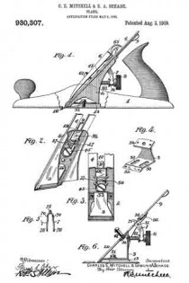
ln the drawings: Figure 1 is a side elevation partly in section of a plane embodying the improvements of our invention. 2 is a perspective view from the rear of the parts which immediately support a plane iron. Fig. 3 is a rear elevation of the same with what may be termed yoke portion of Fig. 4. Fig. 4 is a perspective view from the front of this so-called yoke portion. Fig. 5 is a view partly in section of the Y-adjustment lever which is used with the part of Fig. 2. Fig. 6 is a side elevation and section of the plane iron supporting member and adjusting devices.

In Fig. I the stock or base portion of the plane is represented as shown at 1 which may have as usual a rear handle and a forward knob for convenience in handling the same. In the base of the stock portion is provided the usual throat or opening 10, and to the rear a chair or seat 13. Above the chair is supported the part 2 which may he herein termed the frog and which provides the immiediate support or bearing for a plane iron. Beneath this frog is what may be conveniently termed a yoke portion 3 which may he attached to the frog as hereinafter set forth. The plane iron 4 which rests upon the face of the frog is in the form shown provided with a plate 5 at its upper surface. These are in turn held in place by a cap iron 6 and are provided with the Y-adjustment lever 7 coacting with an adjusting nut 8. A laterally adjusting lever 9 is secured at the top of the frog.

The yoke portion 3 which is formed at the lease in a manner suitable to cooperate with the chair portion 13 of the stock 1, is provided with slots or holes 30. Through these holes pass the screws 31 which secure the yoke portion to the base and thus provide a forward and backward adjustment for the position of the frog. The front end 32 of the base portion of the yoke may be bent downward at an angle to correspond with the under surface of the face of the frog to which it may be secured, as for example by rivets. The upright portion or back of the yoke extends upward and is secured at the downwardly bent portion 36 to the frog at a point just above the opening 20 in the face of the frog. Through this opening access may be had readily to the securing screws 31 in the base.

When the plane iron and plate are adjusted in position and secured to the frog by means of the cap iron 6 and cap screw 61, the frog is subjected to stresses of considerable amounts. To provide for meeting these stresses it is desirable that the sides of the frog should be bent down and depressed to form reinforcing flanges. It will be noted that these flanges as shown are substantially triangular in form and correspond in depth from the face of the frog very closely to the diagram of changes in bending moments which would occur in a beam loaded in the center and supported at the ends, which is the case that we have herein. The cap iron 6 is provided with a cam lever 65 for effecting the requisite pressure between the cap and the plane iron or the plane iron plate for holding the parts in place.

The upper end of the bearing face of the frog is depressed in a truss-like form at 29 to provide a recess in which the lower end of the aterally adjusting lever 9 may be pivoted at 92 and operate. The end of this lever 9 may be provided as is usual in planes of this character with a disk 94 which cooperates with a slot 40 in the plane iron 4 to effect the desired lateral adjustment. The depth of the cutting edge of the instrument may be adjusted by means of what is known as a Y-adjustment 7 in which the nose 75 projects forward through an opening in the face of the frog into a hole 50 in the plate which is above the plane iron. The plane-iron and plate being secured together by the screw 45, movement up and down of the Y-adjustment will also operate the plane iron itself.

The face of the frog is provided with a perforation or recess to receive the head of the securing screw which is thus let into the platform and allows the plane iron to have a smooth and even bearing upon the face of the frog. Above this recess the metal of the frog may be cut out and bent back in the form of ears 27 which will provide bearings for the pivot of the Y-adjustment. In order that these ears may be bent back at convenient angles and with as little injury to the metal as possible, it is desirable that the sides of the recess should be cut back both above and below the ears and at the base thereof as shown particularly in Fig. 3. ln order that the Y adjustment 7 may have a secure and even bearing and also to increase the economy and efficiency of the device, we have made the Y-adjusting lever 7 of sheet metal as shown in Fig. 5, in which 70, 70 are perforations in the two opposite sides of the lever to provide for the pivot pin. It will thus be seen that the lever has two bearings and that they are spaced apart a considerable distance. The lower ends of the arms 78 coact with the adjusting nut 8 which operates on the screw 81. in this construction as shown particularly in Fig. 6 the adjusting screw 81 is conveniently seated in the back of the yoke at a point near the top thereof where the strength and rigidity of the same would be sufficient to give it a secure bearing. lt is also desirable that the face of the frog should have a reinforcing piece at the point where the cap screw 61 is attached thereto. The bent down portion 36 of the yoke provides this in a most satisfactory manner. By this structure also the cap screw tends to aid in holding the yoke and the frog more securely together. The upper portion 33 of the back of the yoke may be out away as appears most clearly in Fig. 3, and thus provide an easy and convenient access for the purpose if desired of riveting the plate 36 to the frog 2. The lower front end of the yoke acts also as a reinforcement to the lower front edge or toe of the frog in the structure herein shown, and materially adds to the strength and efficiency of the parts since the pressure of the lower end of the cap iron 6 is applied near this point. The cutting edge of the plane iron may be projected through the throat or slot 10 in the base of the stock portion just in front of the toe of the frog. The face of the frog is also reinforced as shown by the depressed portion 29 which in stamping the article forms a corrugation at that point substantially opposite the point of application of the pressure applied by the cam lever 65 at the upper end of the cap iron.

The whole structure is exceedingly light in weight and although very simple and economical in its construction is durable and efficient.

The yoke 3 forms a backing for the plane-iron and may be referred to in some of the claims by the term backing or frog backing.

What we claim is:

1. In a plane the combination of a stock-portion having a throat therein for the passage of a plane-iron, a chair at the rear of said throat, a sheet metal frog adapted to sit upon said chair, a plane-iron bearing against the face of said frog, a plate for said plane-iron, a screw for securing said plane-iron and said plate together, a perforation through the face of said frog forming a cavity to receive the head of said screw the head of said screw being accessible from the rear of said frog, the sides of said frog being depressed to form supporting flanges, substantially as described.

2. In a plane the combination of a stock-portion having a throat therein for the passage of a plane-iron, a chair at the rear of said throat, a sheet metal frog sitting upon said chair, a plane-iron bearing against the face of said frog, a plate reinforcing said plane-iron, a screw for securing said plane-iron and said plate together, a recess in the face of said frog forming a cavity to receive the head of said screw, pivot ears formed from the metal of the face of said frog and bent above said recess forming bearings for the pivot of an adjustment lever.

3. In a plane the combination of a stock-portion having a throat therein for the passage of a plane-iron, a chair at the rear of said throat, a sheet metal frog sitting upon said chair, a plane-iron bearing against the face of said frog, a plate for said plane-iron, a screw for securing said plane-iron and said plate together, a perforation through the face of said frog forniing a cavity to receive the head of said screw, pivot ears formed frori the metal of said frog and above said cavity forming bearings for the pivot of an adjustment lever, said adjustinent lever being formed of sheet metal and having bearings in the opposite sides thereof, substantially as described.

4. In a plane the combination of a stock-portion having a throat therein for the passage of a plane-iron, a raised chair at the rear of said throat, a sheet metal frog for said chair, a plane-iron bearing against the face of said frog, a plate over said plane-iron, a screw for securing said plane-iron and said plate together, a perforation through the face of said frog forming a cavity to receive the head of said screw the head of said screw being accessible from the rear of said frog, the sides of said frog being depressed and forrning triangular shaped supporting flanges for said frog resting on said chair, the forward edge of said frog projecting downward beyond the chair and resting on the sole back of the throat and forward of the chair.

5. In a plane, a stock-portion having a chair seat therein, a frog adapted to support a plane-iron and adjacent parts, the sides of said frog being depressed to form supporting and reinforcing flanges and a sheet metal yoke portion secured to said frog, and means for securing said yoke portion to said frog portion, substantially as described.

6. In a plane, the combination of a stock-portion, a frog for supporting a plane-iron, the said frog being formed of sheet metal having the opposite sides depressed to forrn supporting and reinforcing flanges, a yoke secured to said frog forming a seat for said frog, and a screw secured in said yoke portion and adapted to carry a means for adjusting the cutting depth of a plane-iron.

7. In a plane, a stock-portion having a chair therein, a sheet metal frog adapted to support a plane-iron, screws for securing said frog to said stock-portion, a perforation through the face of said frog to permit of access to the said screws, a plane-iron having a plate at the top thereof, a screw for securing said plate and said iron together, a perforation in the face of said frog to receive the head of said screw, a lever for laterally adjusting the position of said plane-iron, a depressed portion from the face of said frog to form a recess to receive said laterally adjusting lever, pivot ears struck from the metal of said frog and bent down to form bearings for an adjustment lever, the metal of the face of said frog being cut away above and below at the sides of said ears, substantially as described.

8. ln a plane, a stock-portion having a chair therein, a sheet metal frog adapted to support a plane-iron, screws for securing said frog to said stock-portion, a perforation through the face of said frog to permit of access to said screws, a plane-iron having a plate at the top thereof, a screw for securing said plate and said iron together, a perforation in the face of said frog to receive the head of said screw, a lever for laterally adjusting the position of said plane-iron, a depressed portion from the face of said frog to form a recess to receive said laterally adjusting lever, pivot ears struck from the metal of said frog and bent down to forrn bearings for an adiustrnent lever, the metal of the face of said frog being out away at the sides of said ears, and a yoke portion secured to said frog forming a reinforce therefor, and providing a bearing for a cap screw and also a bearing for an adjusting screw.

9. ln a plane, a sheet metal frog forrned with depressed side flanges, a sheet metal yoke having slots in the base thereof for adjusting-screws, said yoke being bent down at the upper portion and secured to the underside of the face of said frog, substantially as described.

10. ln a plane, a sheet metal frog formed with depressed side flanges, a sheet metal yoke having slots in the base thereof for adjusting-screws, said yoke being bent down at the upper-portion and secured to said frog, and a cut out portion in the face of said frog below the point of attachrnent of the upper end of said yoke, whereby access may be had to the slots in the base of said yoke, as and for the purpose specified.

11. In a plane, a frog formed of sheet metal having the sides depressed to form supporting flanges , a yoke formed of sheet metal and separately therefrom but united to the underside of the face thereof at the lower end and also at the upper end by a bent down portion, substantially as described.

12. ln a plane, a stock-portion, a frog for and forming a bearing for a plane-iron, means for securing said frog to said stock-portion, a plane-iron secured to the face of said frog, a plate secured to said plane-iron, a screw for fastening said plate to said iron, a recess in the face of said frog forming a cavity to receive the head of said screw, bearings formed integral with said frog and above said recess, an adjustment lever formed of sheet metal and having its nose projecting upward into a hole in said plate and having bearings in the two opposite sides thereof for a pivot therefor, and means for operating said adjusting lever, substantially as described.

13. In a plane, a stock-portion, a frog for and forming a bearing for a plane-iron, means for securing said frog to said stock-portion, a plane-iron secured to the face of said frog, a plate secured to said plane-iron, a screw for fastening said plate to said iron, a recess in the face of said frog forming a cavity to receive the head of said screw, pivot bearing ears formed integral with said frog, the face of said frog being out away at the sides near the upper and lower edges of each pivot bearing ears for the purpose specified.

14. In a plane, a stock-portion, a frog for supporting a plane-iron, a yoke portion formed of sheet metal and secured to said frog portion and having slots in the base thereof for receiving securing screws and a support in the rear thereof for carrying a Y-adjustment screw.

15. In a plane, a frog formed of sheet metal having a perforation near the top thereof to receive a screw-head, a yoke portion formed of sheet metal and at its lower forward edge parallel to the face of said frog portion, the base of said yoke portion being bent back from the face of said frog to form a bearing surface and slotted to receive securing screws, the back of said yoke portion being adapted to form a bearing for an adjustment lever screw, and means for securing the upper end of said yoke to said frog.

16. In a plane, a frog formed of sheet metal having a recess near the top thereof to receive a screw-head, a yoke portion formed of sheet metal and secured at its lower forward edge to said frog portion, the base of said yoke portion being bent back from said frog and having holes to receive securing screws, the back of said yoke portion being adapted to form a bearing for an adjustment screw, the upper end of said yoke being bent downward and forward and parallel to the face of said frog, and means for securing said bent down portion to said frog.

17. In a plane, a frog formed of sheet metal adapted to support a plane iron, a yoke portion formed of sheet metal and at its lower forward edge secured to said frog portion, the base of said yoke portion having holes to receive securing screws, the back of said yoke portion being adapted to form a bearing for an adjustment screw, the upper end of said yoke forming a supporting means for a cap screw.

18. In a plane, a frog formed of sheet metal adapted to form a bearing for a plane iron, a yoke-portion formed of sheet metal and secured at its lower edge to said frog portion, the base of said yoke portion having holes to receive securing screws, the back of said yoke portion being adapted to form a bearing for an adjustment screw, and means for securing the upper end of said yoke to said frog, the sides of said frog being depressed to form reinforcing flanges about said yoke portion.

19. In a plane, a plane stock, a chair portion therein, a frog adapted to carry a plane-iron, a sheet metal yoke secured to said frog having a base portion and being secured at its upper portion to the said frog and having a back portion extending from said upper portion to said base, said back portion being narrowed at the top adjacent said top portion to facilitate attaching the said top portion to the said frog.

20. A frog for a plane said frog being formed of wrought metal, the opposite edges being turned downwardly, a sheet metal frog-backing to the rear and underneath said frog, permanently secured to the frog, and means for removably securing the backing to the plane stock.

21. In a plane, the combination of a stock portion, a frog formed of sheet metal and adapted to support a plane iron said frog having downwardly extending flanges formed integrally with its face, a rearwardly extending sheet metal member carried by said frog and substantially parallel to the upper surface of the sole of said stock portion an upward extension therefrom secured to the back of the frog and means for securing said frog to said stock portion whereby it may be adjusted backward and forward on its seat.

22. In a plane, a plane stock, a frog formed of sheet metal and having reinforcing side flanges, a sheet metal frog-backing formed separately from said stock and said frog, means for securing said backing to said frog and means for adjustably securing said backing to said stock to permit said frog to be adjusted to and fro and a passage through the frog to afford access to the last mentioned means.

23. A frog for a plane, said frog being formed of sheet metal, downwardly extending integral side flanges and a separately formed sheet metal downwardly extending and reinforcing backing secured to the frog.

24. A frog for planes, said frog being formed of sheet metal, a separate backing attached thereto and extending downwardly and to the rear thereof, screws for securing said frog to the plane, a passage through the face of the frog to afford access to the screws, an opening in the upper part of the frog and integral lugs adjacent to said opening and a lever pivot-ed between said lugs.

25. In a plane, a stock portion, a frog therefor formed of sheet metal and having at downwardly extending backing securely fixed at the rear thereof end resting on the stock, and means for removably securing the same thereto.

26. In a plane, the combination of a stock portion, a sheet metal frog adapted to support a plane iron and a reinforcing sheet metal yoke portion secured to said frog, said yoke portion having a downwardly extending member, a forwardly extending member and a further downwardly and forwardly extending member, the letter being secured to said frog adjacent its foward lower end.

27. In plane, a stock portion, a frog carried thereby, a plane iron and cap carried by said frog, a lever for adjusting said plane iron formed of sheet metal and having side arms connected by an integral bend forming a double nose for engagement with the plane iron, and an adjusting member cooperating with said side arms for moving said lever.

Signed at New Britain, Conn., this 2d day of May 1902.

CHARLES E. MITCHELL.
EDMUND A. SCHADE.
Witnesses:
H. S. WALTER,
W. J. WORAM.

No. 787,054 – Plane (Edmund A. Schade And Albert F. Schade) (1905)

[paiddownloads id=”618″]787054


UNITED STATES PATENT OFFICE.

_________________

EDMUND A. SCHADE AND ALBERT F. SCHADE, OF NEW BRITAIN, CONNECTICUT, ASSIGNORS TO
STANLEY RULE & LEVEL COMPANY, OF NEW BRITAIN, CONNECTICUT, A CORPORATION OF CONNECTICUT.

PLANE.

_________________

SPECIFICATION forming part of Letters Patent No. 787,054, dated April 11, 1905.
Application filed October 22, 1904. Serial No. 229,520.

_________________

To all whom it may concern:

Be it known that we, EDMUND A. SCHADE and ALBERT F. SCHADE, citizens of the United States, residing at New Britain, Hartford county, Connecticut, have invented certain new and useful Improvements in Planes, of which the following is a full, clear, and exact description.

Our lnvention relates to improvements in planes.

The object of the invention is to provide a plane with an adjustable tilting handle, so that it may be grasped by the hand and operated in many positions and cases where at present a plane cannot be used except with great danger of accident to the knuckles and the back of the hand, which are liable to be bruised.

The invention is illustrated in the accompanying single sheet of drawings.

The body of the plane carries a bearing for the handle, so that the handle can be tilted to either side and secured in place or used in a vertical position, as is customary.

Figure 1 is a side elevation of a plane, showing those parts which embody the improvements of our invention in vertical section. Fig. 2 is a fragmentary detail showing the parts for securing the handle in position. Fig. 3 is a vertical cross-section showing the method of attachment. Fig. 4 is a plan view of a fragment of the body of a plane, showing the bearing for the handle.

1 indicates the body of a plane, which may be of any suitable character and constructed of any suitable material. The frame herein shown is made of cast-iron.

2 is a knob which may conveniently be provided at the front end of the plane, as is common.

3 is a handle of suitable conformation and material.

4 is a bearing for the handle, which extends lengthwise of the body for some distance. This is shown integral with the body; but it is obvious that it may be made separate and bolted or riveted or otherwise secured in place.

5 is a pin or roller which is mounted in the bearing-block 4 and adapted to rotate or oscillate from side to side through a limited extent.

6 is a rod which is screw-threaded at the lower end and takes into the pin 5.

7 is a screw-cap cooperating with the upper end of the rod 6 for securely clamping the parts together.

The parts are preferably assembled by first attaching the rod 6 to the pin 5, then slipping the handle member 3 over the rod 6, and lastly fixing the cap 7 in place. By tightening the cap the handle may be securely held in place on its seat on the bearing-block 4 in any position, as indicated, for instance, in dotted lines in Fig. 3, While this construction is exceedingly simple, it does provide a means for avoiding such accidents as in the past have been quite common when using an ordinary plane in certain positions — such as, for instance, planing deep rabbets or when operating upon jack-boards. The handle, moreover, may be secured in place in the ordinary upright position for usual work.

It is obvious that many changes may be made in the details of construction without departing from the spirit or scope of our invention.

What we claim is —

1. In a plane, the combination of a body or stock portion having a long semicylindrical bearing, a handle member having a corresponding semicylindrical bearing, a pin mounted to oscillate in the body portion and a rod passing through said handle member and secured to said pin with means to coact therewith for clamping the handle in position at different angular positions.

2. In a plane, the combination of a body or stock portion having a longitudinal bearing, a handle tiltingly seated thereon, a pin mounted in said body portion and a rod passing through said handle and screwed into said pin with means for coasting therewith and clamping said handle in position.

3. In a plane the combination of a body portion having a bearing, a handle mounted to tilt thereon, a pin rotatably mounted in said stock portion beneath said bearing, a rod passing through said handle and screw-seated in said pin and a cap coacting with said rod and said handle and accessible for clamping said handle in position.

Signed at New Britain, Connecticut, this 20th day of October, 1904.

EDMUND A. SCHADE.
ALBERT F. SCHADE.

Witnesses:
W. J. WORAM,
E. G. HOFFMAN.

No. 769,408 – Plane (Edmund A. Schade) (1904)

[paiddownloads id=”608″]769408


UNITED STATES PATENT OFFICE.

_________________

EDMUND A. SCHADE, OF NEW BRITAIN, CONNECTICUT, ASSIGNOR TO STANLEY RULE & LEVEL COMPANY, OF NEW BRITAIN, CONNECTICUT, A CORPORATION OF CONNECTICUT.

PLANE.

_________________

SPECIFICATION forming part of Letters Patent No. 769,408, dated September 6, 1904.
Application filed June 4, 1904. Serial No. 211,073. (No model.)

_________________

To all whom it may concern:

Be it known that I, EDMUND A. SCHADE, a citizen of the United States, residing at New Britain. in the county of Hartford, State of Connecticut, have invented certain new and useful lmprovements in Planes, of which the following is a full, clear, and exact description.

My invention relates to improvements in planes.

The object of my invention is to provide means for adjustment of the plane-iron and means for locking the same to prevent accidental movement.

The invention consists in improvements the principles of which are illustrated in the accompanying single sheet of drawings.

Figure 1 is a side elevation of a plane embodying the improvements of my invention. Fig. 2 is a detail fragmentary view showing the parts particularly necessary for comprehension out my improvement, a portion of the figure being shown in section.

1 indicates the body of a plane of any suitable construction. This in the form shown has handles 2 and 3. 4 is a frog of any suitable construction which provides a bearing for the plane-iron 5. 6 is a plate winch serves to reinforce the plane-iron and in this particular instance affords the means of connection for the adjusting mechanism. 7 is a cap-screw which takes into the frog in any well-known manner. 8 is a cap coacting therewith, and 9 is a clamp for holding the parts in their proper position. All of these parts thus far described may be of any suitable construction.

The cutting depth or position of the plane-iron may be varied by means of a lever, which is commonly termed a “Y adjustment.”

In the drawings, 10 indicates a pivot-pin carried by the frog and upon which the adjustment-lever is mounted.

11 is the nose of the lever, and 12 is one of the depending arms.

13 is a screw-post which is securely fastened to the frog 4.

14 is an operating-sleeve mounted to operate on the post 13 and having, preferably, a milled head 15.

16 is a shoulder or flange carried by the inner end and adapted to coact with the arm 12 of the adjusting-lever.

17 is a member which is carried by the sleeve 14. This aliords a bearing for one side of the arm 12 of the Y adjustment, so that when the sleeve 14 is moved longitudinally on the post 13 the arm 12 is rocked to and fro to move the cutting-iron.

The adjusting-sleeve 14; as commonly constructed is likely to accidentally turn and move on the post 13 as the plane is used. This results sometimes in derangement of the adjustment of the plane and at all times tends to wear the parts unduly. By my construction this is avoided. The member 17 is preferably milled on the edge and may be adjusted on the post 14 to securely engage the arm 12 and clamp the same in position against the flange 16. The friction of the parts against the arm 12 serves to prevent the adjusting-sleeve from rotating on the post 13. As a consequence the adjusting-lever cannot move and the sleeve has no free play to cause wear on the parts. The plane-iron may be adjusted by releasing the clamping mernber 17 and then operating the adjusting-sleeve. The advantages of this construction will be apparent to those skilled in this art.

What l claim is —

1. In a plane, the combination of a body portion, a frog, a plane-iron and adjusting member, a post, a sleeve adjustable on said post and coacting with said member and a clamping member mounted on said sleeve and also coacting with said member for the purpose specified.

2. In a plane, the combination of a body portion, a frog, a plane-iron, an adjusting member coasting therewith, a screw-threaded post, an adjusting-sleeve screw-threaded on said post, a clamping-sleeve screw-threaded on said adjusting-sleeve and rotatable therewith and also independently thereof said sleeve and clamping member coacting with said adjusting member for the purpose specified.

Signed at New Britain, Connecticut. this 1st day of June, 1904.

EDMUND A. SCHADE.
Witnesses:
H. S. WALTER,
W. J. WORAM.

No. 738,501 – Plane (Alix W. Stanley And Edmund A. Schade) (1903)

[paiddownloads id=”589″]738501


UNITED STATES PATENT OFFICE.

_________________

ALIX W. STANLEY AND EDMUND A. SCHADE, OF NEW BRITAIN, CONNECTICUT,
ASSIGNORS TO STANLEY RULE & LEVEL COMPANY, OF NEW BRITAIN,
CONNECTICUT, A CORPORATION OF CONNECTICUT.

PLANE.

_________________

SPECIFICATION forming part of Letters Patent No. 738,501, dated September 8, 1903.
Application filed February 11, 1903. Serial No. 142,845. (No model.)

_________________

To all whom it may concern:

Be it known that We, ALIX W. STANLEY and EDMUND A. SCHADE, citizens of the United States, residing at New Britain, in the county of Hartford, State of Connecticut, have invented certain new and useful Improvements in Planes, of which the following is a full, clear, and exact description.

This invention relates to planes, and particularly to improvements in the construction of that class of planes adapted to be used on curved surfaces, sometimes called “circular planes.” In planes of this character the base or sole is made flexible, so that it may be bent to any desired curve to cause the plane to fit onto a curved surface, either concave or convex. The sole portion of the plane is usually made of sheet metal, such as spring-steel. It is highly desirable in planes of this character that means be provided whereby the adjustment of the sole to the desired curve may be effected accurately and quickly. To that end, therefore, the main object of this invention is to provide simple and effective mechanism for attaining these results.

In the accompanying drawings, Figure 1 is a side elevation illustrative of a specific embodiment of my invention, the sole of the plane being curved to fit to a concave surface. Fig. 2 is a fragmentary perspective view of detached details of construction.

1 is the main body portion.

2 is the base or sole portion. The sole portion 2 is capable of being curved relatively to the main body portion 1. In the form shown the portion 1 is connected to the middle portion of the sole 2.

3 is the frog, carried by the frame 1 and in turn supporting the plane-iron 4. and the adjustments therefor. It is not necessary to explain in detail the adjustments for the plane-iron, because they are well known and constitute no part of this invention.

5 is a screw-threaded post mounted in a suitable screw-threaded bearing on the forward part of the body 1.

6 is a knob or handle carried by the post 5. When said post is rotated it will move up and down relatively to the body 1.

7 is a telescopic extension of the post 5. The connection between the post 5 and its extension 7 is screw-threaded. The screw-threads on the post which take into the frame 1 are right-hand threads, while the screw-threads on the extension 7 which take into the post are left-hand threads, or vice versa. The post extension 7 is connected to a lever 8 by means of a link 9. The lever 8 is pivotally mounted in the body 1. The link 9 prevents the extension 7 from rotating. The particular screw-threaded adjustment of the post 5 relatively to the frame 1 and the extension 7 relatively to the post 5 produces double the movement of the lower end of the extension 7 that would be produced were the link 7 merely projected into the post 5 without being oppositely screw-threaded. The lever 8 is connected with one end of the sole 2 by means of the link 11. 10 is another lever pivotally mounted in the body 1 and connected to the opposite end of the sole 2 by the link. 12.

15 is a pivot for the lever 8.

16 is a pivot for the lever 10. 13 14 are segmental gears fixed on the pivots 15 16, respectively, so that the movement of one of said levers will be transmitted to the other — for example, the movement of the lever 8 by the aforesaid means will produce a corresponding movement in the lever 10. Hence as the lever 8 is moved upwardly the sole 2 will be curved upwardly. If the lever 8 is moved downwardly, the sole 2 will be curved downwardly, and the position of the levers 8 and 10 and the degree and direction of curvature of the sole 2 are deterininable solely by the handle 6. By means of a suitable indicating device it may be ascertained whether the sole is flat or curved and if curved what degree of curvature exists in the sole. In the particular form shown the indicating device comprises a pointer 17, carried by one of the parts — for example, the body 1 — in such a position as to project into the path of movement of certain graduations carried by another part — for example, the segmental gear 13. Referring to Fig. 1, it will be seen that the pointer 17 projects into a curved slot in the segmental gear 13, adjacent to which curved slot there are certain graduations from zero upward and downward. These graduations indicate degrees of curvature in the sole. When the zero-mark on the graduated scale lies opposite the pointer or line of reading, it indicates that there is no curve in the sole. If any one of the graduations above the zero-mark is brought into line with the pointer, it indicates to the user that the sole is curved upwardly to a certain definite degree. The reverse is true of the graduations below the zero-mark. It might be said that the segmental gear 13 constitutes a movable pointer, which enables the user to accurately set the plane so that the sole will be curved to any desired degree to fit to any particular curved surface, and this adjustment may be accurately and quickly effected without any preliminary trials, such as fitting the plane to the particular curved surface upon which it is desired to operate. When the plane has been set as desired, a set-screw 18 may be operated to clamp the adjusting screw or post 5 and prevent accidental displacement. The set-screw 18 may operate to clamp a split collar on the frame 1, through which the adjusting-post 5 passes.

The subject-matter disclosed and claimed herein is a specific embodiment of the invention broadly claimed in Alix W. Stanley’s application for United States Letters Patent, Serial No. 142,844, filed February 14, 1903.

What is claimed is —

1. A plane for cutting curved surfaces comprising a body portion, a sole portion secured thereto, adjusting-arms pivotally secured to the body portion and connected to the sole portion, segments of gears carried by the pivotal supports, an index or scale carried by one of said segments, and a stationary indicator or pointer carried by the body portion of the plane coacting with the scale or index whereby the degree of curvature of the sole portion may be indicated.

2. A plane comprising a body portion, a flexible sole portion secured thereto, a pair of arms pivoted in said body portion and connected to the ends of the sole portion, an index or scale carried by one of said arms, and a relatively stationary indicating member carried by the body portion of the plane and coacting with the scale or index for indicating the degree of curvature.

3. A plane for cutting curved surfaces comprising a body portion, a sole portion secured thereto, a pair of arms pivoted to the body portion and connected to the sole portion, gear-segments mounted to operate with said arms, one of said segments being slotted and having a scale or index adjacent the slotted portion, and an indicating member carried by the body portion of the plane cooperating with the scale or index for the purpose specified.

Signed at New Britain, Connecticut, this 7th day of February, 1903.

ALIX W. STANLEY.
EDMUND A. SCHADE.
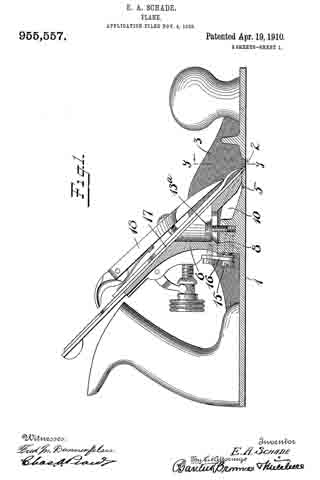
Witnesses:
ROBERT N. PECK,
WILLIAM J. WORAM.

No. 553,322 – Miter Or Bevel Plane (Justus A. Traut And Edmund A. Schade) (1896)

[paiddownloads id=”521″]553322


UNITED STATES PATENT OFFICE.

_________________

JUSTUS A. TRAUT AND EDMUND A. SCHADE, OF NEW BRITAIN, CONNECTICUT,
ASSIGNORS TO THE STANLEY RULE AND LEVEL COMPANY, OF SAME PLACE.

MITER OR BEVEL PLANE.

_________________

SPECIFICATION forming part of Letters Patent No. 553,322, dated January 21, 1896.
Application filed October 1, 1895. Serial No. 564,327. (No model.)

_________________

To all whom it may concern:

Be it known that we, JUSTUS A. TRAUT and EDMUND A. SCHADE, citizens of the (United States, residing at New Britain, in the county of Hartford and State of Connecticut, have invented certain new and useful Improvements in Miter or Bevel Planes, of which the following is a specification.

This invention relates to planes, more particularly of that class designated as “miter” or “bevel” planes; and the object of the invention is to provide an improved plane of this class more especially adapted for work on moldings and similar materials, whereby the same can be properly planed to permit the same to be joined with a miter or bevel joint, as desired.

The further object of the invention is to provide adjustable means in connection with and preferably embodied in the adjusting or gaging means whereby said adjustable means can be adjusted and held in engagement with the stock of the plane at whatever angle the gaging or adjusting means maybe positioned, to thereby constitute at all times a support for the material, whether the gaging means be adjusted in position adjacent to the plane-stock or not, and also to provide means in connection with such adjustable means whereby when the same is in engagement with the stock of the plane the projecting plane-iron will not strike the same, on the movement of the plane in either direction.

In the accompanying drawings, forming a part of this specification, Figure 1 is a top view of my improved miter or bevel plane, and showing a piece of work in position to have one of its ends cut at an angle of forty-five degrees, whereby, in connection with a similar molding it will form a miter-joint. Fig. 2 is a front view of the miter or bevel plane, showing the plane proper drawn away from the work. Fig. 3 is also a top view, parts thereof being broken away, and shows the gaging or adjusting means disposed at an angle of about eighty degrees relatively to the race or guideway of the plane, and also shows, in dotted lines, the adjustable means in connection with the gaging device for supporting the material in its position adjacent to the stock of the plane, and Fig. 4 is a transverse partly-sectional view, in line a a, Fig. 1, looking toward the right hand in said figure.

Similar characters designate like parts in all the figures of the drawings.

Our improved miter or bevel plane, in the preferred form thereof herein shown and described, comprises a suitable supporting means or base (designated in a general way by A) for supporting a suitable plane (designated in a general way by B) adapted to be moved to and fro thereon, a suitable adjustable gaging or adjusting means (designated in a general way by C) for supporting the work at any desired angular position relatively to the plane B, and adjustable means (designated in a general way by D) preferably embodied in the gaging or adjusting means for supporting the work in position adjacent to the plane, whether the gaging means be adjusted to a position adjacent to the plane or not, and which embodies means for preventing the plane-iron from striking said adjustable means.

The supporting means or base A may be of any desired and suitable construction adapted to support the devices above mentioned, and is provided with a race or way 10, constructed in any suitable way, in which the stock 11 of the plane B is adapted to move to and fro. Adapted to slide in this race 10 is a plane B, constructed in any suitable way to accomplish the desired object. In the form shown, however, it comprises a right-angled stock 11, one member b of which slides in the race or way 10, while the other member c thereof, which is at right angles to the supporting means A, is provided with the plane-mouth 15, hereinafter described. The members b and c may be secured together in any suitable way and reinforced by suitable ribs, as desired. Secured to this stock 11, preferably adjacent to the juncture of the members b and c thereof and in any suitable manner, but preferably by means of a bracket 12, formed integral with said stock, is a handle 13 for operating the plane. The member c of the stock is provided with a mouth 15, preferably formed at an angle relatively to the longitudinal axis of said member c. Adjacent to this mouth 15 the stock 11 in the interior thereof is provided with a suitable bracket 16 for supporting the plane-iron 14 and its adjusting and clamping mechanism, which adjusting and clamping mechanism may be, if desired, of the usual form, and hence no further description thereof is deemed neccessary. This plane-iron supporting-bracket 16, however, is also disposed at an angle relatively to the stock member c and in parallelism with the mouth 15 of the plane, and is provided with an inclined or beveled seat 16′ for the plane-iron, whereby said plane-iron 14 when in its working position will have its knife-edge projecting through said mouth 15 at an angle to the member c of the stock, whereby one part of the work will be operated upon before the other part thereof and the breaking or tearing of the fibers of the wood prevented when the plane-iron leaves the material. By means of this particular construction of plane-iron bracket the plane-iron can be made of the usual form and thickness, as in the ordinary planes, and whereby the necessity of making the plane-iron somewhat thicker at one than at the other side thereof in order to obtain an angular cut, as has heretofore been necessary, is obviated, and whereby also the sharpening of the knife-
edge of the iron is facilitated.

The gaging or adjusting means C for holding the material in proper angular position to be planed consists, in the preferred form thereof herein shown and described, of a suitable bracket 20, pivoted to the base A, preferably at the forward end thereof adjacent to the race 10, and which bracket is adapted to swing in an arc of a circle, and by the means hereinafter described support the material at any desired angle relatively to the race or member c of the plane-stock 11. This bracket 20 of the form shown is constructed of an arm 21 and a vertical plate 22, preferably integrally connected at their inner ends and diverging from each other, and through the juncture of the same the pivot screw or bolt 23 projects to pivotally secure the bracket for swinging movement relatively to the base A. This bracket-plate 22 is preferably provided with a curved inner end 24, whereby the bracket-plate 22 can be swung into any desired position adjacent to the plane-stock without the end thereof striking against the stock member c when the same is at the forward end of its race.

Preferably integral with and connecting the plate 22 and arm 21, adjacent to the outer ends thereof, is a preferably-curved member or arm 25, having an arc-shaped slot 26 therein. This arm 25 preferably extends beyond the point of juncture with the member or arm 21, and is provided at its outer end with a sleeve 27, carrying a locking device held therein by any suitable means. ln the preferable form thereof the locking device consists of a vertically-sliding bolt 28, provided with a recess (not shown) on its side face, which a pin or screw (likewise not shown) extending through the wall of the sleeve at right angles to said bolt 28 intersects, whereby the locking-bolt is permitted to have a sliding movement and is prevented from bein g drawn out. This locking-bolt 28 is provided with a suitable actuating-handle or finger-piece 20 for manipulating the same.

The base A is provided with apertures 30, disposed in an arc of a circle similar to the arc of the slotted member 25, and in position to be engaged by the lower end of the locking-bolt 28,whereby on the swinging of the bracket 20 the same can be located in any desired position by pushing the locking-bolt 28, which may be a spring-operated bolt, if desired, into any one of these apertures 30.

Any number of apertures may be provided, whereby the bracket can be located at any desired angle relatively to the race or plane stock.

In order to firmly secure the gaging or adjusting means in its adjusted position and prevent the movement thereof when the plane is in use, the bracket is provided with a supplemental fastening means in the nature of a suitable clamping device 31, and which in the form shown comprises a clamping-bolt 32, having a threaded end and an enlarged head 33, and provided with a suitable actuating-handle or sliding lever 34. The threaded end of this clamping-bolt projects through the arc-shaped slot 26 of the arm 25 and enters suitable threaded apertures 35 in the base, which apertures are likewise disposed in an arc of a circle in alignment with the locking-bolt openings 30. Any desired number of these threaded apertures may be provided. Intermediate of the upper face of the arm 25 and the under face of the enlarged head 33 a suitable washer 36 is disposed, whereby on the turning of the clamping-bolt said bracket will be clamped in the position in which the locking-bolt 28 positioned the same.

The adjustable means for holding the work in position to be operated on relatively to the plane-stop member c in the preferred form shown consists of a suitable fence or gage plate 40, adjustably secured to the bracket-plate 22 for sliding movement to and from the in movable plane. The means herein shown for securing this fence or gage plate 40 to the bracket-plate 22 comprises a suitable slot 41 in the bracket-plate 22, through which a screw-threaded stud preferably integrally secured to the fence 40 is adapted to project. A thumb-nut 43 is adapted to screw onto the end of this threaded stud to clamp the adjustable fence in any desired position, a suitable washer 44 being disposed between the inner face of the thumb-nut and bracket-plate 22.

When the bracket 20 is in the position shown — as, for instance, in Fig. 1 — the adjustable fence 40 is adjusted to permit a part of its inner end, as hereinafter described, to engage the stock member c of the plane and be clamped in such position, whereby the material can be placed in position against such fence to permit the same to be operated on by the plane. When it is desired to change the angle of the bracket 20, the same is adjusted to any desired position — for instance, as shown in Fig. 3 — in which the bracket is shown in its adjusted position at an angle of eighty degrees relatively to the race; but in order to form a proper support to hold the material in position to be planed it is necessary that the fence 40 be adjusted to have a part of its inner end engage the stock member c, the same as shown in Fig. 1. Hence, by releasing the clamping device 43 and moving the fence 40 into the position shown in dotted lines (see Fig. 3) and reclamping the fastening device the fence 40 will have a part of its inner end in engagement with the stock and in proper position to support the material. By means of this improved adjustable fence or gage plate 40 the said fence can be adjusted to permit a part of its inner end to properly engage with the stock at whatever angle the bracket 20 may be adjusted.

If, however, the entire inner end of the fence engaged the stock member c, the plane-iron in its to-and-fro movements would strike against the edge of such fence and hack the knife-edge thereof. In order, therefore, to prevent this serious disadvantage and at the same time permit the fence 40 to be adjusted into such position relatively to the stock member that it will properly support the work in position to be operated on by the plane, in whatever position the bracket 20 may be adjusted, I provide the inner end of the fence with a projection or projecting portion 44′, adapted to engage the stock member c of said plane at a point beyond the knife-edge of the plane-iron, and which in this instance is shown disposed above the upper edge of the plane-iron, whereby this projecting portion 44′ alone engages the stock of the plane when the adjustable fence is in position to support the work, and the knife-edge in the to-and-fro movements of the plane is permitted to pass by the adjacent recessed portion of the inner end of the fence, and the injury of the same thereby obviated.

It is obvious that it is advantageous to thus cause the fence to bear against the face of the plane-stock rather than, for instance, against a fixed part of the frame, as it is possible that, owing to wear, the plane may not always occupy exactly the same position relative to any lined point on the frame.

By means of this improved miter or bevel plane the work can be held at all times in proper position adjacent to the plane to be operated upon from any angle to which the bracket constituting a part of the gaging device is adjusted, and the liability of injuring the knife-edge of the plane also prevented.

Having thus described my invention, I claim —

1. In a plane of the class described, the combination with a support; of a plane movable thereon; a bracket pivoted to said support for adjustment in an angular direction relatively to said movable plane; a fence adjustable relatively to said bracket and having a projection thereon adapted to engage a portion of the movable plane, whereby the knife-edge of said plane is permitted to pass free from contact with said fence, substantially as described.

2. An adjustable gage for a plane of the class described, consisting of a bracket adapted to be pivoted adjacent to the stock of a movable plane for adjustment in an angular direction relatively to said plane, and carrying an adjustable plate or fence movable with said bracket and adjustable relatively thereto, to and from the movable plane, and having a projection thereon adapted to engage a portion of the movable plane from any position to which said bracket may be adjusted, substantially as described.

3. In a plane of the class described, the combination with a support; of a plane movable thereon; a bracket pivoted to said support for adjustment in an angular direction relatively to said movable plane and embodying a supporting plate; a fence, having a projection thereon, and secured to said supporting-plate for adjustment in parallelism therewith and movable with said bracket, whereby the projection is adapted to engage a portion of the movable plane, to permit the knife-edge of said plane to pass free from contact with said fence, substantially as described.

4. In a plane of the class described, the combination with a support havinga race or way-and also having apertures disposed in an arc of a circle; of a plane movable in said race; gaging means pivoted to said support for adjustment in an angular direction relatively to said movable plane, and comprising a bracket having a projecting arm and a vertical plate connected adjacent to their inner ends, and an arm connecting said vertical plate and projecting arm adjacent to their outer ends, and having an arc-shaped slot therein, an adj ustable locking device secured to said slotted arm, an adjustable clamping device movable in said slotted arm, said locking and clamping devices being adapted to engage apertures in the support, a fence secured to said bracket-plate and adjustable relatively thereto, and having a projection on its inner end adapted to engage the stock of the movable plane from any position to which the bracket may be adjusted, and a clamping device for securing said adjustable fence in its adjusted position, substantially as described.

5. In a plane of the class described, the combination with a support; of a plane movable thereon, and comprising a right-angled stock having a mouth therein disposed at an angle to the longitudinal axis of the plane; a plane-iron bracket secured to said stock, and also disposed at an angle to the longitudinal axis of the plane and in parallelism with the mouth of said plane; a plane-iron seated on said bracket and adapted to project through said mouth, whereby the knife-edge thereof will likewise be at an angle to the longitudinal axis of the plane; a bracket pivoted to said support for adjustment in an angular direction relatively to said movable plane; a fence adjustably connected to said bracket, and having a projection on its inner end adapted to engage a portion of the stock of the plane to permit the knife-edge thereof to pass free from contact with said fence, substantially as described.

6. In a plane of the class described, the combination with a support; of a plane movable thereon; a bracket pivoted to said support for adjustment in an angular direction relatively to said movable plane; a fence secured to said bracket for adjustment to and from the movable plane, and having a projection at its upper, inner end adapted to engage the plane-stock when said fence is adjusted into position relatively to said stock, whereby the knife-edge of the plane is permitted to pass below said projection and free from contact with the inner edge of the adjustable fence, substantially as described.

7. An adjustable gage for a plane of the class described, consisting of a bracket adapted to be pivoted adjacent to the stock of a movable plane, for adjustment in an angular direction relatively to said plane, and carrying an adjustable fence or plate movable with said bracket and adjustable relatively thereto, to and from the movable plane, and having a projection thereon adapted to engage a portion of the movable plane from any position to which said bracket may be adjusted; and means for clamping said bracket in its adjusted position, substantially as described.

8. An adjustable gage for a plane of the class described, consisting of a bracket adapted to be pivoted adjacent to the stock of a movable plane, for adjustment in an angular direction relatively to said plane; an adjustable fence or plate movable with said bracket and adjustable relatively thereto, to and from the movable plane, and having a projection thereon adapted to engage a portion of the movable plane from any position to which said bracket may be adjusted; means for adjustably clamping said fence to said bracket; and means for clamping said bracket in its adjusted position, substantially as described.

JUSTUS A. TRAUT.
EDMUND A. SCHADE.
Witnesses:
H. S. WALTER,
F. N. STANLEY.

No. 545,732 – Plane (Edmund A. Schade) (1895)

[paiddownloads id=”516″]545732


UNITED STATES PATENT OFFICE.

_________________

EDMUND A. SCHADE, OF NEW BRITAIN, CONNECTICUT.

PLANE.

_________________

SPECIFICATION forming part of Letters Patent No. 545,732, dated September 3, 1895.
Application filed June 5, 1895. Serial No. 551,754. (No model.)

_________________

To all whom it may concern:

Be it known that I, EDMUND A. SCHADE, a citizen of the United States, residing at New Britain, in the county of Hartford and State of Connecticut, have invented certain new and useful Improvements in Planes, of which the following is a specification.

This invention relates to planes, and especially to that class of tools commonly known as “smoothing-planes,” and it has for its object to provide an improved supporting and adjusting device for the plane-knife or plane-iron, whereby the same can be quickly and accurately adjusted with relation to the work to be done, and also to provide an improved clamping device for said plane knife or iron, whereby the same will be firmly held against vibration in the use of the plane.

In the drawings accompanying and forming part of this specification, Figure 1 is a vertical longitudinal section of a plane embodying my improvements, parts of said figure being shown in full lines. Fig. 2 is a plan view of a portion of the plane, illustrating certain features of the construction, a part thereof being shown in section. Fig. 3 is a transverse section taken in line a a, Fig. 1, looking toward the right hand; and Fig. 4 is a top view of the improved clamping device detached, a part thereof being broken away.

Similar characters designate like parts in all the figures of the drawings.

This improved plane, in the preferred form thereof herein shown, consists of a suitable stock or body, designated generally as 100, adapted for co-operating with those elements in which my invention particularly resides. This stock 100 is shown as provided with a suitable handle 55 at one end thereof and with the usual actuating-knob 60 at the opposite end thereof. The stock has formed in its sole the usual transverse mouth 10, the forward wall of which is designated 11 and the rearward wall as 12.

In the rear of the mouth 10 the stock is provided with a plane-iron carrier seat or support 13 of a construction suitable for the purpose herein set forth. This carrier seat or support 13 is shown as having its upper face 14 thereof preferably on a plane parallel with the sole of the stock and thereby forms a horizontal carrier-support for the plane-iron carrier-bracket and is preferably integrally connected with said stcck and extends transversely entirely across the stock, being united with the mouth of the plane by means of an inclined portion 15. This carrier seat or support 13 is somewhat thicker in cross-section than the sole of the stock to adapt it to receive the locking devices of the plane-iron or knife-carrier hereinafter described. Instead of the seat or support 13 extending entirely across the stock, the knife-carrier seat or support may, if desired, consist of a pair of longitudinal shoulders on a plane parallel with the sole of the stock and extending inwardly a short distance from the sides of the plane.

In this case, however, an intermediate horizontal support must be provided to receive the locking devices of the knife-carrier, hereinafter described. When the seat or support 13 is constructed of a solid member extending entirely across the stock, as is the preferable construction, said carrier support or seat has a recess 16 therein forming two parallel longitudinal guideways 17, Fig. 3. A knife or plane-iron carrier or bracket 20 is adjustably supported on the carrier seat or support by means of binding-screws 21, hereinafter described, and is adapted to slide in the guideways 17, and has a recess 18 in its under side to engage the guideways 17 of the carrier support or seat. This carrier-bracket is shown as having a vertically-inclined side 22 relative to the sole of the stock, adapted to receive the plane iron or knife 23, and is provided at its under side with a horizontal bearing-face parallel with the face 14 of the support 13, and is adapted to slide on said carrier support or seat. The carrier is extended below its horizontal face 14 to form a support 24 for the lower end of the knife, and is preferably V-shaped, to permit the under edge thereof to be inclined parallel with the inclined portion 15, connecting the mouth of the stock and the carrier seat or support. A suitable adjusting device for the plane-iron carrier-bracket, designated in a general way by A, is provided for adjusting said carrier-bracket and thereby the knife relative to the mouth of the stock, and is shown comprising suitable bracket-arm 26, preferably integrally connected to the stock of the plane, and in the upper end of which a threaded spindle 27, provided with a suitable thumb-nut 23, is journaled, the screw end thereof working in a suitable screw-threaded recess in the rear side of the carrier. By turning said thumb-nut the carrier-bracket will be adjusted to the desired position by sliding upon its horizontal support or seat toward or from the mouth of the stock.

In order to adjustably secure or clamp the carrier-bracket upon its seat or support 13, binding-screws 21 are preferably used and are passed through elongated slots 31 in that portion of the carrier which has its upper face in a plane parallel with the lower or seat-engaging face of the carrier-support, in order that the carrier may be moved relatively to its seat or support without effecting the positioning of the binding-screws, and to permit this the carrier is shown as having recesses 23 countersnnk therein and communicating with the inclined face 22 of said carrier. Washers 30 are disposed between the heads of the binding-screws and the horizontal upper face of the carrier-bracket, and said carrier-bracket, by means of the elongated slots 31, can be adjusted in longitudinal direction of the stock by means of the adjusting device A, hereinbefore described. By this particular construction and organization of the plane-iron or knife-supporting members of the plane iron or knife a perfect adjustment of the plane is obtained, and, moreover, a perfectly rigid support for the plane-iron or knife-carrier-bracket is provided. Any suitable means for vertically adjusting the plane-iron may be used, but is shown as comprising a lever 35, pivoted at 36 to the carrier, and having its upper end in engagement with the cap-plate 23′ for actuating the same toward and from the plane-mouth, and thereby moving the plane-iron in the same direction. This lever has the usual forked tailpiece 37 engaged by a peripheral groove in an adjusting-nut 38, which works longitudinally upon a screw or threaded post 39, fixed to the carrier.

As a means for clamping the plane-knife 23 and its usual cap-plate 23′ in position, I have provided an improved clamping device, designated in a general way by B, and which comprises a main clamping-lever having a supplemental clamping-lever connected therewith, and thereby forming a double clamping-lever, which, in the preferred form thereof, is shown consisting of a main clamping-lever 40, working on a fulcrum-screw 41, disposed on the carrier-bracket and having pivoted to its upper end the usual actuating cam-lever 42, having its cam-face 43 in operative engagement with the upper face of the cap-plate.

Pivotally connected to the main clamping-lever 40, at any suitable place thereon, and projecting beyond the lower clamping end of said lever, is a supplemental clamping-lever 45 of any suitable construction adapted for the purpose herein set forth and of comparative flexibility relative to the main clamping-lever. The main clamping-lever 40 has recesses 46, and is provided with laterally-projecting pins or studs 47, upon which the supplemental clamping-lever is adapted to swing by means of suitable ears or lugs 48, having apertures therein adapted to engage said pins or studs. As a means for adjusting this supplemental lever, the upper end thereof is provided with a suitable adjusting device, herein shown as a set-screw 49, adapted to work on the upper surface of the main clamping-lever. This supplemental clamping-lever also has an elongated aperture 51 to permit the fulcrum-stud 41 to be adjusted into position. By means of this improved clamping device, one lever of which is adapted to engage the cap-plate at a point beyond the clamping end of the other lever, the knife or plane-iron is firmly held at different points near its working end, and vibration thereof in the use of the plane is substantially eliminated.

Having thus described my invention, what I claim is —

1. In a plane, the combination with a stock, and with a plane-iron supported thereon; of a clamping device for the plane-iron comprising two clamps, one of said clamps clamping the plane-iron at a point in advance of the clamping-point of the other clamp, substantially as described.

2. In a plane, the combination with a stock, and with a plane-iron supported thereon; of a clamping device for the plane-iron comprising two clamps, one of said clamps clamping the plane-iron at a point in advance of the clamping-point of the other clamp; and means for separately operating the clamps, substantially as described.

3. In a plane, the combination with a stock; of a carrier-bracket supported thereon; a plane-iron adjustably supported on said bracket; a cap-plate adapted to rest on said plane-iron; and clamping means for said plane-iron comprising a main clamping-lever fulcrumed on the carrier-bracket and a supplemental clamping-lever pivotally adjustable on said clamping-lever and adapted to clamp the cap-plate at a point beyond the clamping-point of the main-lever, substantially as described.

4. In a plane, the combination with a stock; of a plane-iron adjustably supported on said stock; and clamping means for said plane-iron comprising a main clamping-lever fulcrumed on the stock, and a supplemental clamping-lever pivotally adjustable on said main clamping-lever, and adapted to clamp the plane-iron at a point beyond the clamping-point of the main-lever, substantially as described.

5. In a plane, the combination with a stock; of a plane-iron adjustably supported on said stock; a cap-plate adapted to rest on said plane-iron; and clamping means for said plane-iron comprising a double-lever fulcrumed to the stock, one of said levers clamping the cap-plate at a point beyond the clamping-point of the other lever, substantially as described.

6. In a plane, the combination with a stock; of a plane-iron adjustably supported on said stock; a cap-plate adapted to rest on said plane-iron; and clamping means for said plane-iron comprising a main clamping-lever fulcrumed on the stock; and a supplemental clamping-lever pivotally adjustable on said main clamping-lever and adapted to clamp the cap-plate at a point beyond the clamping-point of the main-lever, substantially as described.

7. In a plane, the combination with a stock; of a plane-iron adjustably supported on said stock; a cap-plate adapted to rest on said plane-iron; and clamping means for said plane-iron comprising a double-lever, the main clamping lever thereof being fulcrumed to the stock and the supplemental clamping-lever being pivotally adjustable on said main-lever; and means for adjusting said double-lever, whereby the adjustable action of the combined levers extends to the clamping ends of both the main and supplemental clamping-levers, substantially as described.

8. In a plane, the combination with a stock; of a plane-iron adjustably supported on said stock; a cap-plate adapted to rest on said plane-iron; a main clamping-lever fulcrumed on said stock; means for adjusting said lever; a supplemental clamping-lever pivotally adjustable on said main-lever and adapted to clamp the cap-plate at a point beyond the clamping-point of the main clamping-lever; and means for adjusting said supplemental-lever relative to the main-lever and independently thereof, substantially as described.

9. In a plane, the combination with the stock having a transverse mouth; of a horizontal carrier-support disposed thereon; and a carrier-bracket having a bearing-face substantially parallel to the horizontal face of the support, and adapted to slide on said support, and also having a vertically-inclined side adapted to support a plane-iron, said inclined side extending below the bearing-face of the horizontal support to support the plane-iron adjacent to the mouth of the stock; a plane-iron adjustably supported on said bracket; means for longitudinally actuating said carrier-bracket relatively to its support; means for adjusting the plane-iron on its inclined support; a cap-plate resting on the plane-iron; and a clamping device for said plane-iron comprising a main clamping-lever fulcrumed to the carrier-bracket; an adjusting device for said main clamping-lever; a supplemental clamping-lever pivotally adjustable on said main-lever, and adapted to clamp the cap-plate at a point beyond the clamping-point of the main-lever; and means for adjusting said supplemental-lever independently of the main-lever, substantially as described.

10. In a plane-iron, the combination with a stock; of a plane-iron adjustably supported on said stock; a cap-plate adapted to rest on said plane-iron; a main clamping-lever fulcrumed on said stock and adapted to clamp said cap-plate and plane-iron; an adjusting device for said main-lever; a supplemental clamping-lever pivoted on the main-lever at a point below the fulcrum-point of said main-lever, and adapted to clamp the cap-plate and plane-iron at a point beyond the clamping-point of the main clamping-lever; and an adjusting device for said supplemental-lever, whereby said supplemental clamping-lever is adjustable independently of the main clamping-lever, substantially as described.

EDMUND A. SCHADE.
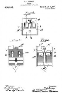
Witnesses:
H. S. WALTER,
CHAS. B. STANLEY.

No. 473,087 – Plane-Iron (Edmund A. Schade) (1892)

[paiddownloads id=”486″]473087


UNITED STATES PATENT OFFICE.

_________________

EDMUND A. SCHADE, OF NEW BRITAIN, CONNECTICUT, ASSIGNOR TO
THE STANLEY RULE AND LEVEL COMPANY, OF SAME PLACE.

PLANE-IRON.

_________________

SPECIFICATION forming part of Letters Patent No. 473,087, dated April 19, 1892.
Application filed January 8, 1891. Serial No. 377,120. (No model.)

_________________

To all whom it may concern:

Beit known that I, EDMUND A. SCHADE, a citizen of the United States, residing at New Britain, in the county of Hartford and State of Connecticut, have invented certain new and useful Improvements in Plane-Irons, of which the following is a specification.

My invention relates to improvements in plane-irons; and the objects of my improvement are to facilitate the manufacture of the plane-iron, to improve its quality when made, and to make the plane-iron capable of being worn down farther than the old style of iron used in connection with certain planes.

In the accompanying drawings, Figure 1 is a side elevation of my plane-iron with cap-iron attached. Fig. 2 is a plan view of the under side of said plane-iron as laid upon the cap-iron, illustrating the manner of putting the two together; and Fig. 3 is a face view of the plane-iron in position upon the frog of the plane-stock and much worn, a portion of the plane-stock being shown in section.

The general form of the plane-iron B is the same as that in ordinary use, and the cap-iron C, with its large-headed holding-screw D, is also of ordinary construction. I provide the plane-iron B with a longitudinal slot 4, through which the body of the holding-screw D passes in holding the cap-iron upon the plane-iron and permitting the cap-iron to be adjusted up and down thereon. Instead of making the enlargement to let pass the head of the screw D, at the upper end of the plane-iron, as in the ordinary plane, I form said circular enlargement 5, at the end of the slot 4, which is nearest the cutting-edge 6. This enlargement comes so near the cutting-edge that when the screw is in the enlargement and the cap-iron and plane-iron have their edges parallel to each other, the cap-iron will project considerably over the cutting-edge. If the two parts should be held in this position when the head of the screw is being passed through the enlargement 5, in order to assemble the plane-iron and cap-iron, and then the cap-iron should be drawn upwardly to bring the screw into the slot the cap-iron would be liable to strike the cutting-edge and dull it. Instead of assembling the parts in this manner, the cap-iron and plane-iron should be held at right angles to each other and the screw-head passed through the enlargement 5, as shown in Fig. 2. The cap-iron may then be drawn upward to the upper part of the plane-iron to bring its screw into the slot and the cap-iron then turned around and secured in position, as shown in Fig. 1.

In Fig. 3 I have illustrated the plane-iron as nearly worn out by repeatedly grinding off its edge, and I have shown the same in connection with a plane-stock E, its frog F, and a laterally-adjusting lever G, having a roller 7, that projects and enters the slot 4; in the plane-iron for adjusting the same laterally. 8 designates the upper end of the lever that takes into the cap-iron for adjusting the plane-iron endwise, all as in ordinary planes; but in said figure the cap-iron is not shown, in order to better show the friction-roller 7 of the laterally-adjusting lever as it lies in the slot of the plane-iron. It will be seen that this friction-roller is still some distance from the upper end of the slot and that it may still properly engage the plane-iron until the latter is worn much shorter than shown, and so short as to wear into the circular enlargement 5 at the lower end of the slot. I have also shown in Fig. 3 in broken lines, as at 9, the contour of the circular enlargement, which is ordinarily at the upper end of the plane-iron, and it will readily be seen that with such an enlargement at the upper end of the plane-iron the laterally-adjusting lever would be inoperative.

By my improvement I adapt the plane-iron to be worn down closer than in the ordinary plane-iron and to operate in connection with the laterally-adjusting lever until the plane-iron is completely worn cut. By making the circular enlargement at the end of the slot, which is nearest the cutting-edge, I am enabled to make the plane-irons by pressing them out from sheet-steel and to harden and temper them to a point up to or beyond the lower edge of this circular enlargement with less liability of cracking the plane-irons at this point, so that fewer irons are lost in hardening and tempering, and they are less liable to become cracked or broken at said point after they are put into use. This is because there are no angular notches at the lower end of the slot from which a crack will start, and because the slot opens into the circular enlargement, so that it is less liable to strain in the expansion and contraction of the metal during the hardening and tempering process. Care is generally taken in hardening the ordinary plane-bit not to harden it quite up to the slot ; but by my improvement such care is not necessary.

I claim as my invention —

In a plane, the combination of a plane-iron having a longitudinal slot 4 with the circular enlargement at its lower end, said slot extending up near to the upper end of the bit without any enlargement at said upper end, and a laterally-adjustilig lever having a projecting part fitted to work in the upper end of said slot, substantially as described, and for the purpose specified.

EDMUND A. SCHADE.
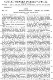
Witnesses:
H. S. WALTER,
F. N. STANLEY.

No. 532,842 – Bench Plane (Justus A. Traut And Edmund A. Schade) (1895)

[paiddownloads id=”65″]532842


UNITED STATES PATENT OFFICE.

_________________

JUSTUS A. TRAUT AND EDMUND A. SCHADE, OF NEW BRITAIN, CONNECTICUT.

BENCH-PLANE.

_________________

SPECIFICATION forming part of Letters Patent No. 532,842, dated January 22, 1895.
Application filed June 20, 1894. Serial No. 515,114. (No model.)

_________________

To all whom it may concern:

Be it known that we, JUSTUS A. TRAUT and EDMUND A. SCHADE, citizens of the United States, residing at New Britain, in the county of Hartford and State of Connecticut, have invented certain new and useful Improvements in Bench-Planes, of which the following is a specification.

This invention relates to that class of bench-planes known as “molding-planes,” the object being to provide an improved plane of that class adapted for doing work of a wide range both in form and size, also means for adjusting the diiferent parts of the plane in all directions, in accordance with the work to be done, while maintaining the simplicity, compactness of construction, and readiness of adjustment and manipulation necessary to a practically operative tool of such comprehensive character.

Our present invention is in the nature of an improvement upon the inventions shown in Letters Patent No. 294,825, granted to Justus A. Traut March 11, 1884, and No. 505,119, granted to Eppie J. McCulloch September 19, 1893.

In the drawings accompanying and forming a part of this specification, Figure 1 is a plan view of a bench-plane embodying our present improvements. Fig. 2 is a side elevation thereof. Fig. 3 is a front elevation of the same. Fig. 4. is a longitudinal sectional side elevation, in line x–x, Fig. 1, of the parts above said line. Fig. 5 is a similar view of the parts below said line. Fig. 6 is a transverse section in line b–b, Fig. 5. Fig. 7 is an elevation detail of the auxiliary runner hereinafter referred to. Fig. 8 is a similar view of an intermediate runner or gage, also hereinafter referred to. Fig. 9 is a transverse sectional end elevation in line y–y, Fig. 1. Fig. 10 is a detail in side elevation, taken from the right, of an adjustable stop or gage, and adjacent parts, to be hereinafter described. Fig. 11 is a similar view of one of the spurs. Fig. 12 is a longitudinal section in line z–z, Fig. 11. Fig. 13 is a detail sectional side elevation of a cutter, its clamping and adjusting devices and adjacent parts. Fig. 14 is a sectional detail in line v–v, Fig. 13. Fig. 15 is a similar view in line w–w, Fig. 13. Fig. 16 is a sectional detail in line u–u, Fig. 14. Figs. 17 to 20, inclusive, are sectional rear elevations, showing. various adjustments ot the tool for different kinds of work. Fig. 21 is a similar view of a modification to be hereinafter described.

Similar characters designate like parts in all the figures.

According to our present improveinents the body-portion of the plane comprises a main stock A, provided with transversely-arranged rods or pins B and C, upon which an auxiliary stock, designated in a general way by D, is adjustable toward or from the main-stock in lateral direction. The rods or pins also support the end gages E and F, which are adapted to be similarly adjusted in lateral direction, to regulate the distance of the cut from the edge of the piece of board or other material to be operated upon. The usual handle, 72, is provided upon the main stock for actuating the plane, and handles, 73 and 74, are secured to the edge-gages in a manner which will be hereinafter more fully described.

The main-stock has secured thereto, by means of rivets or otherwise, the usual steel blade or runner 75; and an adjustable blade or runner, 2, is mounted upon the auxiliary stock D. In order to provide a clear space at the throat of the plane for the shavings to pass out, the front and rear portions of this adjustable runner 2 are permanently connected, preferably by means of a lateral arch or brace, 3, as shown in detail in Fig. 7. The end portions of the auxiliary stock are also connected and supported in a similar manner by means of a second lateral arch or half-ring brace, 4.

The rods or pins B and C are, preferably, each made of a single piece, and are held securely in place in the sockets, 5 and 6, of the main-stock A, by means of binding-screws, 7 and 7’, which admit of lateral adjustment of the rods when the character of the work requires it.

As clearly shown in Fig. 9, the auxiliary stock D is provided with sleeves, 8 and 9, within which the rods B and C are j ournaled, and upon which rods said sleeves, and the connected parts of the auxiliary stock, have a free, sliding, lateral movement. Each of said sleeves is secured within one of the corresponding sockets, 10 and 11, of the auxiliary stock, and said sockets are usually formed integral with the stock itself and its supporting arch 4. The runner 2, the form thereof shown in Fig. 7, is provided with oblique slots, 12 and 13, and said runner is adjusted upon the stock by the play of said slots upon the sleeves 8 and 9. The adjustable runner is held in place laterally by means of flanges, 8′ and 9′, upon the inner ends of the corresponding sleeves. Milled nuts, 14 and 15, are provided upon the outer screw-threaded ends of the sleeves 8 and 9, to hold said sleeves in place, and also for the purpose of obtaining a secure lateral hold upon the runner 2, by means of the flanges 8′ and 9′, and thereby preventing shifting of said runner in lateral direction. The vertical adjustment of the runner 2 is obtained by means of a long screw-rod, 16, preferably provided with right-and left-hand threads of different pitch, to prevent slipping of the screw. The upper end of the screw passes through the threaded shoulder 17, which is cast integral with the body-portion of the auxiliary stock, while the lower end or point of said screw works within a screw-threaded aperture (shown in dotted lines in Fig. 5) in the arch or brace, 3, connecting the front and rear portions of the runner 2. When said screw 16 is turned to the right, — that is, in the usual direction, — the runner will, through its slots 12 and 13, ride down upon the sleeves 8 and 9 ; and conversely, when said screw is turned to the left, the said runner will in the same manner ride up said sleeves. The difference in pitch and direction of the threads upon said screw prevents the slipping of said runner when adjusted to position without further locking; but when desired, the milled nuts 14 and 15 may be turned still farther, to bind the runner firmly in its adjusted position. Binding-screws, 18 and 19, pass through correspondingly-threaded apertures in the sockets 10 and 11, and through longitudinal slots 20 in the sleeves 8 and 9, and impinge and bind against the rods B and C, thus securing the auxiliary stock, with its connected parts, firmly in place upon said rods and in fixed relation laterally to the main-stock A.

Each of the side or edge gages, E and F, is provided with a double sleeve or socket for each of the rods B and C, said sockets being designated in a general way by G. As shown in Fig. 2, said sleeves are formed integral with the body of the gage, are superposed, and are provided with a common binding-screw, 76. This binding-screw works in a threaded aperture, 21, placed transversely and at the median line of the apertures in the sleeves. The points of said screw 76 are beveled, and thus the screws are adapted to bind against the rods B and C, whether said rods are placed in the upper or the lower sleeve-openings, in the manner described in the patents hereinbefore referred to.

For rough work and for work where the plane is set level, the gage E, shown at the right of Fig. 9, is sufficient; but for fine work requiring delicate adjustments of the gage, or an oblique position of the plane with respect to the work, or both, we make use of the adjustable gage F, clearly shown at the left of said Fig. 9. Here the main or fixed rail 77 is provided with the integral sockets 22, two or more in number, and within each of these sockets is a bolt, 23, surrounded by a coiled spring, 24, spanning the space between the inner side of the head of the bolt and the end-wall of the socket, which, as shown, merges into the rail 77. The inner end of said bolt is screw-threaded at 25, as shown, and is set within a correspondingly-threaded aperture in the face of an auxiliary rail 78. The movable rail 78 is adjusted with respect to the main rail 77 by the turning ot the adjusting-screw 79 to the right or left, the force of the spring 24 serving to prevent movement of the parts after the adjustrnent of the movable rail is made. A simple movable rail with a fiat edge or face is sufficient so far as delicacy of adjustment of the gage is concerned; but for tilting the plane to an oblique position, it is necessary that a two-part adjustable rail be provided, the bearing-face of which may oscillate about an axis in the non-oscillatory member thereof.

In Fig. 9, 73 is shown as having a semi-circular rib or tongue upon its inner face, and is provided also with an axially-disposed rod or spindle, 26. The oscillatory rail 80 is concaved to conform to the outline of the rib 27 upon the rail 78; and a screw, 28, passing through the rail 80 and countersunk therein, also passes through a peripheral slot 29 in the rib 27 and is engaged at its point by a threaded recess in the spindle 26. It will, of course, be understood that at least two such connections of the parts 78 and 80 must be made. When the rail 80 is to be adjusted, the set-screw 28 is loosened slightly, and said rail oscillated upon the axis 26 until it is in the proper position, when it is locked there by tightening the screw. By means of this two-part adjustable gage or rail, the plane may be set to any desired slant to conform to the character of the work to be done.

Upon a post on the forward end of the auxiliary stock D, said post being designated in a general way by I, is adjustably mounted a third or intermediate blade or runner 30. The mounting of said runner will now be described, as this feature is one of the essential points of this invention. Working within a transverse guide-way, the lower wall of which is shown at 31, in Figs. 2, 6 and 9, is a laterally-movable slide, 32, that is adapted to be locked in position, when adjusted, by means of a binding-screw 33 and washer 34; the body of the screw working in a guide-slot, 35, traversing said slide longitudinally for the greater portion of its length. From the inner end of said slide rises a post or bracket, designated in a general way by 36, and the inner face of said post is provided with a vertical guide-way, the inner wall of which is shown at 37, in Figs. 6 and 9. The vertical arm 30′ of the intermediate runner 30 is adapted for vertical movement in said guide-way, and is locked, when set in position, by means of a binding-screw and washer, 38 and 39, in the manner just before described, the body of the screw working in the slot or guide 40 in the vertical arm of the runner 30. A fine adjustment of said runner in a vertical direction is secured in the following manner: The post 36 is provided with a vertically-threaded bore parallel with the arm 35 of the intermediate runner, and within this bore is set a threaded rod or spindle, 41. A nut, 42, is adapted to ride up and down the thread of said rod, and carries with it a flange, 43, working in a corresponding slot or recess, 44, in the outer face of the vertical portion of the intermediate runner 30, whereby said intermediate runner is adjusted in vertical direction as desired. When so adjusted, the runner is locked in position in the manner just described. It will be seen that we thus provide both a vertical and a lateral adjustment for this runner, and that these adjustments can be as readily effected as the adjustments of the runner 2 upon the auxiliary stock. These adjustments, moreover, are entirely independent of the adjustments of the auxiliary runner 2, as the adjusting-slides and guide-ways are mounted upon a fixed portion of the toe of the auxiliary stock.

While both of the movable runners are adjusted vertically and laterally, independently of each other, and while each is also independently adjustable, vertically and laterally, of the fixed runner on the main stock A, there is a certain dependency of adjustment of the movable runners, due, however, solely to the inclination of the plane, when at work in a position similar to those shown in Figs. 18, 20 and 21.

For the purposes of our present invention, it is immaterial whether the intermediate runner and its adjusting-means are placed upon the auxiliary stock or upon the main stock, as the intermediate gage would be actuated and controlled in the same manner and perform the same functions in both cases. In Fig. 21 we have shown the said runner, with its adjusting-slides, guides, and adjusting and clamping-screws, mounted upon the main stock, A, of the plane.

Referring now particularly to Figs. 13 to 16, inclusive, the adjusting and clamping-devices for the cutter, or plane iron, will now be described.

45 designates the cutter, which is secured to the adjusting-screw 46 by means of a pin-and-slot connection 47, said screw working in registering threaded apertures in the bracket 46′ and being controlled, in the usual manner, by means of a hand-wheel 48. As will be seen from Fig. 1, the slot in the cutter is upon the extreme outer edge, in line with the edge-wall of the cutter-slot, to adapt the plane for use with wide or narrow irons. Rotation of the adjusting-screw is prevented by means of a pin, 49, working in the longitudinal slot or groove 50 in said screw. When the cutter has been adjusted to the proper depth, it is clamped in position by means of a clamping wedge-bolt, designated in a general way by 51, and working in an aperture or bore, 52, extending entirely through the main stock transversely but in a slightly oblique direction. The head 51′ of this bolt is beveled off to conform with the inner side of the main stock, and the lower face thereof, which binds against the upper side of the cutter 45, is filed off obliquely, as shown at 512, to form a wedge adapted to be crowded against the said face of the cutter and clamp the cutter against the rear wall 53 of the cutter-slot. As will be seen, the action of this clamping-bolt is such that when it is drawn into its bore 52 by the rotation in the corresponding direction of the nut 54, it will wedge against and clamp the cutter in place; while when it is forced out of the said bore by the turning of the nut in the opposite direction, it rises away from and unlocks the cutter. This wedging action, as will be seen, admits of the clamping in position of very wide or very narrow cutters as well as very thick or very thin cutters. In the upper face of the head 51′ of the clamping-bolt, is a slot, 513, co-operating with a pin, 55, passed through the upper wall of the main stock downwardly into the bore 52. This pin-and-slot connection prevents rotation of the clamping-bolt when actuated by the turning of the nut 54, so that only a reciprocatory movement will be imparted to the bolt by the nut. The nut 54 is provided with a circumferential groove or slot, 54’, and is held in place against the outer wall of the main stock, and just within the entrance to the bore 52, by means of a holding-plate, 56, surrounding the narrow portion of the nut at said slot or groove and held to the main stock by means of a set-screw 57. The nut is thus free to turn without danger of falling out of the bore 52.

Directly in front of the clamping-device for the cutter, and upon the outer side of the main stock near the toe thereof, is a depth-gage, or stop, designated in a general way by K, and clearly shown in Figs. 9 and 10. As shown, this gage consists of a face-plate, 81, having a perpendicular adjusting rod or post screw-threaded at 82. This adjusting-rod or bolt works in the vertical bore of a socket, 58, integral with the main stock of the plane, and is raised or lowered by means of a flanged nut, 59, the flange 59′ of which works in a transverse slot or groove, 58’, in said socket, the construction being similar to that of the nut 42 for adjusting the intermediate gage or runner 30. A clamp-nut, 592, holds the screw-post in place when adjusted. A scale, 60, is provided upon the main runner, for convenience of adjustment of the depth-gage, Both the depth-gage and its scale may be duplicated upon the outer side of the auxiliary runner, if desired, the socket for the gage being shown at 61 in Fig. 3, and the scale at 62 in Fig. 2.

When using the cutter or plane-iron as a plow, we throw into operation a spur, 63, rectangular in its general outline, but having rounded spur-points, 63′ and 632. A longitudinal slot, 633, with sloping or beveled walls, extends through the body of the spur and forms a guide-way for a conical-headed set-screw, 64. This spur is set into a vertical recess, 65, in the runner of the main stock, (see Fig. 11) and the spur is held in place within said recess by the expansion of its side-walls by the screw 64 when said screw is forced home within its seat, — the threaded aperture that extends through the main-stock runner transversely, as shown in Fig. 12. A second spur, 66, (as shown in Fig. 2,) is secured to the outer side of the auxiliary runner 2. This arrangement forms a very effective means for locking the spur firmly in place, and is very simple in construction. Either one of the two points of the spur may be brought into operation by removing and re-setting the screw 64, and the spur locked in position against the walls of the runner by the expansion of the thin sides thereof by the screw.

The side-gages or fences are interchangeable and may be used upon either side of the body of the plane. Moreover, the plane-gage E may not only be used upon either side of the stock, but it may also be reversed so that the handle will be nearest the body of the plane, and the rail or face-plate farthest therefrom. This arrangement of the gage is intended particularly for center-beading wide material, for which a very long reach is necessary. This gage, therefore, has its rail or face-plate ground with parallel sides, 67 and 68, so that the work. may be held properly whichever side may be in use. The under sides of the arms, 69, of the gage E are also ground at the points 70 to a plane parallel with the plane of the sole 71 of the rail or face-plate These upper stops thus form a guide or bearing-face on which to run the plane when used upon wide material for center-beading, &c.

The bearings, G, of the side-gages are connected by the handles 73 and 74, in such a manner that they are brought into the proper position for holding the plane with the hand which is not used for grasping the main handle 72. By means of the two side-edges, the material to be operated upon may be held firmly between the two face-plates or rails, so as to steady the plane laterally, and thus, in connection with the runners upon the main and auxiliary stocks, hold the plane to its course. We consider this as of importance, especially when a workman has to use the plane continuously for a considerable period of time. Another advantage arising from the use of two side-gages is that one of them may be set lower than the other, the rods B and C being put through the upper of the bearings G in one gage and through the lower bearings in the other gage, according to the character of the molding to be produced by the work-man. When the side-gage is carried by the rods in the upper bearings thereof, the face-plate or rail of the gage will usually extend below the cutter, so that, if desired, only a portion of the full width of the cutter may be used. Under some circumstances, the said rail may also extend below the cutter when carried by the rods in its lower bearings. The adjustable rail of the gage F is, preferably, provided with an overhanging flange, 83, in order to prevent the choking of the space between the adjustable rail and the main body by the falling of chips and shavings therein.

In Figs. 17 to 21, inclusive, we have illustrated a number of different arrangements or adjustments of the parts of our improved plane for different kinds of work. In Fig. 17 is shown the adjustment for making a tongue. Here the intermediate runner or gage 30 is set for the depth of the tongue, with the main and auxiliary runners at the same level, the side-gages being adjusted to engage the faces of the board. The corresponding groove in the opposite piece of material is made by substituting a proper grooving-cutter for the deep-slotted cutter used for forming the tongue, the position of the intermediate runner being correspondingly altered.

Figs. 19 and 20 illustrate different adjustments of the runners for plain molding from opposite sides of the piece of material. Fig. 21 illustrates a somewhat different adjustment of the runners to that shown in Fig. 20; but here the intermediate runner is mounted upon the main stock of the plane, and the adjustable side gage disposed at the opposite side of the work.

A further modification of the adjustable rail of the side gage F is here shown, at 84, as permitting both upward and downward tilting of the gage, whereby additional adjustability is provided therefor.

We consider as of especial importance the addition to a bench-plane having an auxiliary runner, vertically and laterally adjustable, of a third runner intermediate of the main and auxiliary runners, as by the use of such third runner a central and more perfect bearing-surface is secured for the plane, and the work of the cutter more perfectly and thoroughly accomplished, especially in beading, center-beading, and grooving or rabbeting.

All of the runners are relatively thin and adapted to lie substantially contiguous to one another, so that they will track in correspondingly-narrow and relatively-adjacent grooves or channels in the work, as in forming narrow beads close together upon the material.

As the control of the adjustments of the intermediate gage is entirely independent of the adjustments of the auxiliary runner, readiness of manipulation is assured, and both hands of the workman may be used to simultaneously set the two adjustable runners to the positions desired. As before stated, it is immaterial whether this third gage be mounted upon the main or the anxiliary stock, as the adjustments can be as readily made from the one part of the tool as from the other. It will be observed that a very fine adjustment of this gage is obtained by means of the nut 42 riding upon the spindle 41, and carrying with it the runner. A substantially similar fine adjustment of the depth-gage or gages is also provided, which insures greater accuracy and precision in the laying out of the work to be done. The same may be said of the adjustment of the auxiliary gage or runner by means of its threaded bolt or spindle working in the fixed bracket or shoulder of the auxiliary stock; and a very stiff support is formed by this construction in connection with the clamping-sleeves and nuts upon the supporting-rods for the side-gages of the auxiliary stock. This clamping-sleeve and nut, in connection with the thumb-screws passing through the bore of the bearing of the auxiliary stock and through the slot in the sleeve, form a very secure and rigid clamping-means for holding the stock to said rod and the auxiliary runner to the inner face of the stop by means of the flanged inner end of the sleeve; as by means of the nut upon the outer end of said sleeve the gripping effect of said flange may be increased or diminished at will, to accord with the work being done.

The adjustment and locking of the cutter or plane-iron may be also very perfectly controlled by the setting of the cutter by means of the screw-post or spindle and hand-wheel, and the locking of the clamping wedge-bolt set at an angle sufficient to compensate for variations in thickness of different cutters. By means of the pin-and-slot connection, a very narrow cutter can be as perfectly set and clamped in place as a very wide one. Moreover, the adjusting-nut for said clamping-bolt is at all times in position for use, and cannot possibly be displaced or lost without removing its locking-plate.

By means of the side-gages, an approximate adjustment thereof upon the rods B and C may be obtained, and said gages then locked in position by the usual clamp-screws. A subsequent fine adjustment of the gage having the adjustable rail or face-plate is then effected by the turning of the adjusting-screw 79, which forces said adjustable rail away from the main fixed rail in opposition to the action of the springs. Various modiiications of this adjustable gage may be made, so long as the principle thereof — viz: normally holding said parts together by spring-pressure, and gradually separating them to regulate the distance of the adjustable rail from the fixed rail — is adhered to. As the two side-gages are interchangeable, it will be readily seen that our improved plane can be quickly and easily adjusted to any position for any kind of work, and that mutual adjustability of parts is not confined to the movable runners alone, but is also present in the gages as well. In addition to this, the position of the fixed gage can be reversed at either side of the stock, so as to accommodate material of either narrow or broad widths, a feature of special importance in center-beading upon wide material. The additional vertical adjustments of the gages rendered possible by inserting the rods in either the upper or the lower bearings are also of importance in using a cutter having its cutting-point considerably in advance of its cutting-heel, as one of the gages can then rest in its upper bearings while the other rests in the corresponding lower bearings. It also enables the workman to use either the full width of his cutter or only a portion thereof. The reversibility of the fixed gage is also a very useful characteristic when operating upon wide pieces, as the under sides of the connecting arms joining the fixed rail and the bearings of said gage, being in a plane parallel with the sole of the gage, rest upon the upper edge of the work and practically form a depth-gage therefor, thus steadying the plane, when working upon wide material, in a very perfect manner; and in connection with the outer face of the gage-rail, which is then in contact with the side of the material, a guide is formed which is as accurately adjusted with respect to the work as when the gage is in its usual position. The very long reach obtained by this reversal is, as before stated, especially useful for center-beading work.

The connection of the bearings of the auxiliary stock, and of the toe and heel portions of the auxiliary runner, by means of stiff arches or half-ring braces, forming between them one side of the plane-throat and affording ample clearance for the shavings and chips thrown out by the cutter, is a structural detail which we have found to be of very material importance in actual practice.

The clamping-device for the cutter or plow-iron is not essentially different from those now in use, except that it is placed obliquely to the cutter and the wedge corresponding in shape. By this means we obtain a much firmer hold upon the iron, and the cutter is, moreover, much more readily clamped and unlocked.

Having thus described our invention, we claim —

1. In a bench-plane, the combination with the main stock and its runner, of an adjustable auxiliary stock and runner, an independently-adjustable runner intermediate of said main and auxiliary stocks and carried by one of said stocks and adapted to form a central bearing-face for the plane, and means for positively maintaining said last-mentioned runner in its several positions independently of said first-mentioned runner, all of the runners being relatively thin and adapted to lie substantially contiguous to one another whereby said runners will track in correspondingly-narrow and relatively-adjacent grooves or channels in the work, substantially as described.

2. In a bench-plane, the combination with the main-stock and its runner, of an auxiliary stock laterally adjustable with respect to the main stock, an auxiliary runner mounted upon said auxiliary stock and vertically adjustable thereon, a runner having independent vertical and lateral adjustments with respect to the main and auxiliary runners and carried by one of said stocks and adapted to form a central bearing-face for the plane, and means for positively maintaining said last-mentioned runner in its several positions independently of said first-mentioned runners, all of the runners being relatively thin and adapted to lie substantially contiguous to one another whereby said runners will track in correspondingly-narrow and relatively adjacent grooves or channels in the work, substantially as described.

3. In a bench-plane, the combination with the main stock and its runner, of an auxiliary stock laterally adjustable with respect to the main stock, an auxiliary runner mounted upon said auxiliary stock and vertically adjustable thereon, a third runner also mounted upon the auxiliary stock and adjustable thereon independently of the auxiliary runner and adapted to form a central bearing-face for the plane, and means for positively maintaining said third runner in its several positions independently of the first-mentioned runners, all of the runners being relatively thin and adapted to lie substantially contiguous to one another whereby said runners will track in correspondingly — narrow and relatively — adjacent grooves or channels in the work, substantially as described.

4. In a bench-plane, the combination with the main stock and its runner, of an auxiliary stock laterally adjustable with respect to the main stock, an auxiliary runner mounted upon said auxiliary stock and vertically adjustable thereon, and a third runner also mounted upon the auxiliary stock and vertically and laterally adjustable thereon independently of the auxiliary runner and adapted to form a central bearing-face for the plane, and means for positively maintaining said third runner in its several positions independently of the first-mentioned runners, all of the runners being relatively thin and adapted to lie substantially contiguous to one another whereby said runners will traclr in correspondingly – narrow and relatively – adjacent grooves or channels in the work, substantially as described.

5. In a bench-plane, the combination with the main and auxiliary stocks and runners, of a third runner intermediate of the main and auxiliary runners and carried by one of said stocks and adapted to form a central bearing-face for the plane, a vertical adjusting-arm or slide for said third runner, a laterally-adjustable guide fixed against vertical movement with respect to the main and auxiliary runners, a clamping device for said lateral guide, a threaded spindle upon said guide, a nut traveling upon the spindle and carrying with it the vertical arm of the runner, and a clamping-device for said arm, and adapted to lock said third runner in its vertically-adjusted position, all of the runners being relatively thin and adapted to lie substantially contiguous to one another whereby said runners will track in correspondingly — narrow and relatively — adjacent grooves or channels in the work, substantially as described.

6. In a bench-plane, the combination with the main stock and its runner, of lateral rods extending from said main stock, an auxiliary stock mounted upon said rods and adjustable in lateral direction thereon, an auxiliary runner having oblique parallel guides adapted to engage said rods to positively maintain said runner in parallelism with the cutter or plane-iron, and an adjusting-screw working in a bore in the auxiliary stool; in parallelism with said oblique guides and controlling the vertical adjustment of t.he auxiliary runner and adapted to transmit the force ot said runner to the auxiliary stock in a line parallel with said guides, whereby said auxiliary stock forms a positive stop for said runner longitudinally of the adjusting-screw and maintains said runner securely in its adjusted position, substantially as described.

7. In a bench-plane, the combination with the main stock and its runner, of lateral rods extending from said main stock, an auxiliary stock mounted upon said rods and adjustable in lateral direction thereon, an auxiliary runner having oblique parallel guides adapted to engage said rods and to positively maintain said runner in parallelism with the cutter or plane-iron, and a right-and-left-hand adjusting-screw working in a bore in the auxiliary stock in parallelism with said oblique guides and controlling the vertical adjustment of the auxiliary runner and adapted to transmit the force of said runner to the auxiliary stock in a line parallel with said guides, whereby said auxiliary stock forms a positive stop for said runner longitudinally of the adjustingscrew and maintains said runner securely in its adjusted position, substantially as described.

8. In a bench-plane, the combination with the main stock; and runner, of lateral rods extending frorn said main stock, flanged sleeves mounted upon said rods and carried in bearings in the auxiliary stock, an auxiliary runner guided upon said rods obliquely parallel with the cutter or plane-iron and supported laterally between the flanges of said sleeves and the adjacent bearing-faces of the auxiliary stock, and an adjusting-screw mounted upon the auxiliary stock and controlling the vertical adjustment of the auxiliary runner and adapted to maintain said auxiliary runner in its adjusted position, substantially as described.

9. In a bench-plane, the combination with the main stock and runner, of lateral rods extending from the main stock, screw-threaded flanged sleeves mounted upon said rods and carried in bearings in the auxiliary stock, an auxiliary runner guided upon said rods obliquely parallel with the cutter or plane-iron, and supported laterally between the flanges of said sleeves and the adjacent bearing-faces of the auxiliary stock, adjusting-nuts upon said sleeves, and an adjusting-screw mounted upon the auxiliary stock and controlling the vertical adjustment of the auxiliary runner and adapted to maintain said auxiliary runner in its adjusted position, substantially as described.

10. In a bench-plane, the combination with the main stock, and lateral rods extending therefrom, of an auxiliary stock having bearings in line with said rods, laterally-adjust able flanged sleeves carried in said bearings and mounted upon said rods, the flanges of said sleeves adapted to carry between them and the adjacent bearing-faces of the auxiliary stock the auxiliary runner and thereby positively maintain said auxiliary runner against lateral movement, registering-apertures in the bearings and sleeves, and clamp-screws working in said apertures and adapted to lock the auxiliary stock to the rods, substantially as described.

11. In a bench-plane, the combination with the main stock and runner, and lateral rods extending from said main stock, of an auxiliary stock and runner, laterally-adjustable sleeves mounted upon said rods and carried in bearings in the auxiliary stock, and means carried by said sleeves forming with the auxiliary stock vertical guides adapted for directing the corresponding movements of the auxiliary runner and for positively locking said auxiliary runner against lateral displacement, substantially as described.

12. In a bench-plane, the combination with the main stock and runner, and lateral rods extending from said main stock, of an auxiliary stock and runner, laterally-adjustable sleeves mounted upon said rods and carried in bearings inthe auxiliary stock, means upon said sleeves engaging the auxiliary runner, and means for clamping said sleeves and runner aud forming with the auxiliary stock vertical guides adapted for directing the corresponding movements of the auxiliary runner and for positively locking said auxiliary runner against lateral displacement laterally in their adusted positions, substantially as described.

13. In a bench-plane, the combination with the main stock and runner, and lateral rods extending from said main stock, of an auxiliary stock, and runner, means for adjusting said runner vertically upon the auxiliary stock, and laterally-adjustable sleeves mounted upon said rods and carried in bearings in the auxiliary stock, said sleeves adapted to engage the auxiliary runner and form with the auxiliary stock vertical guides for directing the corresponding movements of the auxiliary runner and for positively clamping said auxiliary runner laterally in its adjusted position, substantially as described.

14. In a bench-plane, the combination with the main stock and runner, and lateral rods extending from said main stock, of an auxiliary stock, and runner, laterally adjustable sleeves mounted upon said rods and carried in bearings in the auxiliary stock, means upon said sleeves and co-operating with the face of the auxiliary stock adjacent to said sleeves for clamping the auxiliary runner laterally in its adjusted position, and means for simultaneously clamping the auxiliary stock and sleeves to the rods, substantially as described.

15. In a bench-plane, the combination with the main stock and runner, and lateral rods extending from said main stock, of the auxiliary stock and runner, laterally-adjustable sleeves mounted upon said rods and carried in bearings in the auxiliary stock, means upon said sleeves and co-operating with the face of the auxiliary stock adjacent to said sleeves for clamping the auxiliary runner laterally in its adjusted position, registering-apertures in the bearings and sleeves, and clamp-screws working in said apertures and adapted to lock the auxiliary stock and the sleeves to the rods, substantially as described.

16. In a bench-plane, the combination with the main stock and runner, lateral rods extending from said stock, and an auxiliary stock and runner mounted upon said rods, of gages also mounted upon said rods and upon each side of the body of the plane and adjustable toward and from the stock and adapted to engage the lateral faces of the work and to be positively held thereby against lateral movement relatively to the work when said gages are clamped to the rods, substantially as described.

17. In a bench-plane, the combination with the main stock and runner, and lateral rods extending from said main stock, of a laterally-adjustable side-gage mounted upon said rods and having an auxiliary member laterally and radially adjustable independently of the body of the gage and relatively thereto, and a resilient connection between said auxiliary member and the body of the gage and adapted to hold said members normally in engagement with each other, substantially as described.

18. In a bench-plane, the combination with the main stock and runner, and Iateral rods extending from said stock, of a laterally-adjustable side-gage mounted upon said rods and having a two-part movable rail comprising an intermediate member laterally-adjustable independently of the body of the gage and in parallelism therewith, an oscillatory face-plate hinged to said intermediate member, and a locking-means for said two-part rail, substantially as described.

JUSTUS A. TRAUT.
EDMUND A. SCHADE.
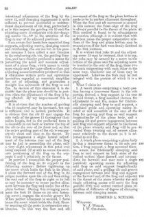
Witnesses:
FRED. J. DOLE,
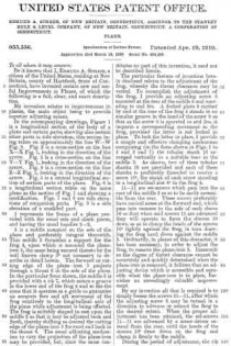
ROBT. U. RUDDELL.