No. 1,012,591 – Plane (Christian Bodmer And Edmund A. Schade) (1911)
[paiddownloads id=”680″]1012591


UNITED STATES PATENT OFFICE.

_________________

CHRISTIAN BODMER AND EDMUND A. SCHADE, OF NEW BRITAIN, CONNECTICUT, ASSIGNORS TO THE
STANLEY RULE & LEVEL COMPANY , OF NEW BRITAIN, CONNECTICUT, A CORPORATION OF CONNECTICUT.

PLANE.

_________________

1,012,591. Specification of Letters Patent. Patented Dec. 26, 1911.
Application filed July 28, 1911. Serial No. 641,094.

_________________

To all whom it may concern:

Be it known that we, CHRISTIAN BODMER and EDMUND A. SCHADE, citizens of the United States, residing at New Britain, county of Hartford, State of Connecticut, have invented certain new and useful Improvements in Planes, of which the following is a full, clear, and exact description.

Our invention relates to a new type of plane adapted to a wide range of work but especially adapted to enable the user to form shallow mortises for hinges, lock face plates, latch strike-plates and the like, with the greatest ease and accuracy. The tool is also designed in such manner that hinge mortises in the jamb and on the edge of a door may be formed without the necessity of using a butt gage, since the plane is equipped with a gage that obviates the use of a separate instrument for the marking out of the mortises. The construction is also such that a mortise may be readily formed in a rabbeted door jamb close to the face of the strike or stop, while the cutter arrangement and length of the plane allows of the forming of a mortise from one and a half inches in length to six inches in length, and also within a few inches, for example, five inches, of the upper casing or lower sill of a door casing. By a very simple adjustment, mortises longer than six inches may be made. The plane may also be used to advantage as a router, and, in the particular form shown herein, can effectively work two inches below the sole of the tool, thus giving a greater range of effective operation than possible with the ordinary router plane. With this outline, it will be seen that the plane is capable of a wide range of usefulness.

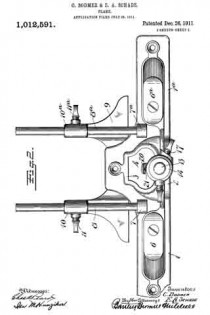
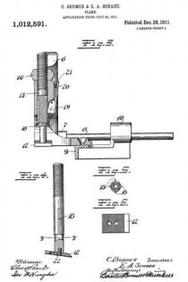
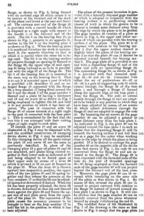
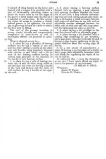
In the drawings Figure 1 is a side elevation of the plane. Fig. 2 is a plan view thereof. Fig. 3 is a section on the line x–x, Fig. 1. Fig. 4 is a side elevation of a detail. Fig. 5 is a section on the line y–y Fig. 4, looking up. Fig. 6 is a plan view of the cutter detached.

1–1a represent the two end sections of the sole of the plane.

2 is a connecting arch extending vertically from the plane of the sole sections 1–1a.

3 is a connecting arch extending horizontally from the sole sections 1–1a.

4 is a chip clearance passage between the arches 2–3.

5 is an upwardly extending tubular guide sleeve located above the arch 2.

6–6a are oppositely facing handles mounted on the two end sections 1–1a of the sole.

7–7a are bosses screw-threaded to receive horizontally extending guide rods 8–8a, when it is desired to use a gage.

9 represents a side gage having sleeves 10–10a arranged to slide upon the rods 8–8a respectively. The lower side of the arch 3 is smoothed off to form a continuation of the two sole sections 1–1a and to give a bearing of substantial width.

12 is a cutter connected to the lower end of an adjustable and slidable carrier post 13. This carrier post is mounted to slide up and down in the guide sleeve 5. The upper end of the carrier 13 is threaded and is provided with an adjustable stop 14 threaded thereon so that by rotating said stop, the downward projection of the carrier post 13 and cutter is limited.

15 is a spring arranged to press the carrier post 13 downwardly. In the preferred arrangement, this spring 15 is coiled around said post and rests at its upper end underneath the arch 2 and at its lower end against a washer 16, which may be rigidly connected to said post 13.

17 is a set screw which enters the guide sleeve 5 laterally, the inner end bearing against the carrier post 13 so that by setting up on said set-screw said post and cutter may be held against sliding movement up and down.

In the particular form shown, it will be seen that the side of the cutter carrier post 13 is provided with a plurality of longitudinal grooves 18–18.

19 is a spline carried by the guide 5, and in this instance hinged so as to be operated by a finger piece 20, said spline being suitably spring-pressed, as by a spring 21, to hold the spline projected into one of the grooves 18. In this instance, the spline and grooves are so placed that the cutting edge of the cutter 12 may be projected toward either end of the plane or laterally in either direction relative thereto. The cutter is preferably detachably connected to the carrier post 13 and is also preferably pitched downward at a slight angle. In this instance, the cutter has its upper surface cross-knurled, the lower end of the guide 13 being correspondingly knurled, so that by the aid of a fastening screw 22, said cutter may be rigidly secured to the lower end of the carrier post. As shown in Fig. 4, the cutter may have two screw passages, whereby, when the forward or cutting edge of the cutter, is worn back, the connection of the cutter to the carrier may be effected by passing the screw 22 through the second or rearmost screw passage.

In forming an ordinary shallow mortise for a hinge strike-plate or lock face-plate, incisions may be made by an ordinary chisel to determine merely the end lines of such a mortise. The gage 9 may be properly set and the cutter carrier post properly set so that it will project the cutter to the desired depth of said mortise, and no more. This being determined, the tool is then applied to the wood, and is preferably started close to the end line of the mortise facing the cutting edge of the cutter. A short chip is then taken. The operator works the plane back step by step until by taking out a succession of short chips he approaches the opposite end line of the mortise, whereupon, by pressing in on the finger-piece 20, the spline 19 is retracted and the cutter may be reversed to the position opposite from that shown in Fig. 1, whereupon the balance of the mortise may be formed without reversin the position of the plane on the piece being cut. During this operation, the cutter yieldingly engages the wood by reason of the spring pressure of spring 15, and will cut down to a depth corresponding to the desired depth of the mortise, at which depth it will be checked by the stop 14 aforesaid. When at the limit of this depth, the bottom of the mortise may be smoothed off by long strokes, so as to properly receive the part to be applied therein. By making the cutter carrier post 13 itself reversible, it is possible to work the tool in either direction in forming a mortise, without disturbing the position of the guide, and hence preserving the proper position of the cutter relatively to the mortise being formed. When the tool is to be used as a router, in some instances it is desirable to shift the tool so that the cutter will stand at right angles to the position shown in Fig. 1. This may be easily accomplished by releasing the spline 19 and shifting said carrier post 13 to the proper position. For routing at considerable depth, it may be desirable to lock the cutter post firmly against vertical movement. This may be accomplished by setting down upon the screw 17.

Obviously, cutters 12 of varying width may be substituted, depending upon the particular work to be performed and the character of wood to be operated upon.

In the above and in a variety of other ways, a mechanic skilled in the art of wood working will find this tool exceedingly useful and capable of performing, quickly and accurately, work which no other tool of the plane type is capable of performing.

What we claim is:

1. In a plane, two oppositely faced connected sole sections, an arch connecting said sections, a reversible cutter carrier, a guide in said arch for said cutter carrier, and means to permit said cutter carrier to move up and down in said guide during the operation of the plane, and disengageable means to hold said carrier against rotation at such times.

2. In a plane, two oppositely faced connected sole sections, an arch connecting said sections, a cutter carrier, a guide in said arch for said cutter carrier, means to permit said cutter carrier to yield longitudinally, said means including a spring for forcing said cutter carrier downwardly.

3. In a plane, two oppositely faced connected sole sections, an arch connecting said sections, a cutter carrier, a guide in said arch for said cutter carrier, means to permit said cutter carrier to yield longitudinally, said means including a spring for forcing said cutter carrier downwardly, and an adjusting stop coacting with said cutter carrier to check said downward movement.

4. In a plane, two oppositely arranged connected sole sections, an arch connecting said sections, an adjustable and reversible cutter carrier in said arch, and a cutter mounted on said carrier in the archway of said arch and a second arch horizontally arranged and constituting a continuation of said sole sections.

5. In a plane, two oppositely arranged connected sole sections, an arch connecting said sections, an adjustable and reversible cutter carrier in said arch, a cutter mounted on said carrier in the archway of said arch, a guide in said arch for said cutter carrier in which said cutter carrier is slidably mounted to permit said cutter to move up and down, and a spring operating to move said cutter in a downward direction and a stop to limit the downward movement of said carrier.

6. In a plane, two oppositely arranged connected sole sections, an arch connecting said sections, an adjustable and reversible cutter carrier in said arch, a cutter mounted on said carrier in the archway of said arch, a guide in said arch for said cutter carrier in which said cutter carrier is slidably mounted to permit said cutter to move up and down, a spring operating to move said cutter in a downward direction, and an adjustable stop mounted on the upper part of said carrier.

7. In a plane, two oppositely arranged connected sole sections, an arch connecting said sections, an adjustable and reversible cutter carrier in said arch, a cutter mounted on said carrier in the archway of said arch, a guide in said arch for said cutter carrier in which said cutter carrier is slidably mounted to permit said cutter to move up and down, a spring operating to move said cutter in a downward direction, an adjustable stop mounted on the upper part of said carrier, and a set screw in said guide to lock said carrier against movement.

8. In a plane, two oppositely arranged connected sole sections, an arch connecting said sections, an adjustable cutter carrier in said arch, a cutter mounted on said carrier in the archway of said arch, and a second arch horizontally arranged and constituting a continuation of said sole sections.

9. In a plane, two oppositely arranged connected sole sections, an arch connecting said sections, an adjustable cutter carrier in said arch, a cutter mounted on said carrier in the archway of said arch, a second arch horizontally arranged and constituting a continuation of said sole sections, and means for connecting a substantially flat cutter to the lower end of said carrier at an angle slightly out of the plane of the bottom of the sole sections.

CHRISTIAN BODMER.
EDMUND A. SCHADE.

Witnesses:
JOSEPH M. HANCE,
TREDICK K. HINE.

_________________

Copies of this patent may be obtained for five cents each, by addressing the “Commissioner of Patents, Washington, D. C.”
_________________

No. 972,645 – Plane (Charles B. Rice) (1910)

[paiddownloads id=”674″]972645


UNITED STATES PATENT OFFICE.

_________________

CHARLES B. RICE, OF WASHINGTON, DISTRICT OF COLUMBIA.

PLANE.

_________________

972,645. Specification of Letters Patent. Patented Oct. 11, 1910.
Application filed April 28, 1910. Serial No. 558,164.

_________________

To all whom it may concern:

Be it known that I, CHARLES B. RICE, a cltizen of the United States, residing at Washington, in the District of Columbia, have invented a, new and useful Plane, of which the following is a specification.

This invention relates to planes of the type which are employed for grooving purposes, although the tool of the present invention is susceptible of other uses if desired.

The object of the invention is to provide a strong simple, durable and inexpensive grooving tool which can be used in a variety of positions and for a large number of useful operations and which can be easily and quickly adjusted to meet the requirements of different kinds of work, such for example as the grooving of doors and door frames for the purpose of securing the door locks and fittings in position.

With the foregoing and other objects in view which will appear as the description proceeds, the invention resides in the combination and arrangement of parts and in the details of construction hereinafter described and claimed, it being understood that changes in the precise embodiment of invention herein disclosed can be made within the scope of the claims without departing from the spirit of the invention.

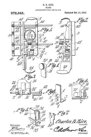
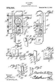
In the accompanying drawing forming part of this specification:– Figure 1 is a plan view of a grooving tool constructed in accordance with the invention. Fig. 2 is a side elevation thereof. Fig. 3 is a transverse section on the line 3–3 of Fig. 1. Fig. 4 is a similar section on the line 4–4 of Fig. 1. Fig. 5 is a detail perspective view showing a modified construction of bit post. Fig. 6 is a detail perspective view of one of the improved bits. Fig. 7 is a view similar to Fig. 6 showing another form of the improved bit. Fig. 8 is a perspective view of the clamping plate.

Like reference numerals indicate corresponding parts in the different figures of the drawings.

The reference numeral 1 indicates a base plate the lower surface 2 of which, as shown in Fig. 2, comprises a bearing surface which fits against the material to be operated upon, the bit 3 being caused to project beyond the bearing surface 2 through the opening 4 formed in the base 1. The base plate 1, at the forward end thereof, is provided with an upwardly extending curved handle or grip 5.

The bit 3 preferably is of the form indicated in Fig. 6. That is to say the bit is formed with a shank or plate 6 with which is adjustably connected the shank or plate 7 of a gage member 8 which determines the distance which the cutting tool 3 shall penetrate into the surface which is being operated upon. The gage 8 preferably consists of a tongue which projects in an oposite direction to the cutting edge of the tool 3. The preferred means of adjustably connecting the shank 7 with the shank 6, consists of a, screw 9 which projects through a slot 10 formed in the plate 7, said slot having an enlargement 11 at one end thereof to permit the initial introduction of the screw 9.

The means for securing the bit or cutting tool 3 in position within the opening 4 in the base plate, preferably consists of a post or standard 14 which, as shown in Fig 3, rises from the face of the base plate 1 adjacent the rear end of the opening 4, said post 14 being extended at its lower end to form the lateral shoulders 15 and the transversely extending flange 16. The shank 7 of the bit gage, and the shank 6 of the bit are fitted flat against the post 14 on the side thereof next to the openings 4 with the cutting edge of the tool projecting through said opening. A rectangular loop member 17 is then fitted downward over the post 14 so as to surround the bit shank 6 and plate 7, said loop member 17 resting at its lower end upon the shoulders 15 as shown in Fig. 5. A plate 18 is then fitted against the rear face of the post 14 between said post and the loop member 17. The plate 18, as shown in Fig. 8, is thickened adjacent its upper end as indicated at 19 and a set screw 20 is threaded through said thickened portion 19. By tightening the set screw 20 the point thereof projects against the rear face of the post 17 and the lower portion of the plate 18 serves to draw the loop member 17 tightly around the bit shank 6 whereby to bind the same firmly in any position to which it has been adjusted on the front face of the post 14.

For the purpose of providing a second bearing surface 25 which is arranged at a right angle to the bearing surface 2 and has an bit 3 projecting therefrom, the base plate 1 is formed or provided along one side thereof with an upstanding flange 26, said flange, as shown in Fig. 2, being formed with an inclined edge 26 which causes it to be narrow at the forward end of the stock of the plane and broad at the rear end thereof. The extreme rear end of the flange 26 is provided with a curved handle 28 which is disposed at a right angle with respect to the handle 5 at the forward end of the stock. The bit 3 on the bearing face 25, as shown in Fig. 1, projects in an opposite direction to the bit 3 on the bearing plate 2 as shown in Fig. 2. When the bearing plate 5 is employed therefore the stock is manipulated in the opposite direction to that in which it is moved when the other bit is being used. The bit 3 on the bearing surface 25 projects through an opening 30 formed in the flange 26, the upper edge of said opening 30 being inclined so as to be in parallelism with the edge 27 of the flange 26. The bit 3 of the bearing face 25 is mounted in the same way as the bearing face 2. That is to say it is mounted upon a post 14 which is provided with shoulders 15 and an enlarged flange 16 connected with the flange 26, a loop member 17 being fitted around the bit 2 and the shank 7 of the gage member 8 thereof and a plate 18 having a thickened end 19 and set screw 20 as shown in Fig. 8 being employed to tighten the bit and hold it in any position to which it has been adjusted. The post 14 connected with the flange 26 of course extends at a right angle to the post 14 connected with the base plate 1. This is necessitated by the fact that the two bits 3 are arranged with their cutting edges at right angles to each other.

If desired, the plate 18 and set screw 20 illustrated in Fig. 8 may be dispensed with, and the modified construction of clamping device shown in Fig. 5 may be employed. In this clamping device all the parts except the plate 18 and screw 20 are the same as previously described. In place of the clamping plate 18 a pair of plates 35 and 36 are employed, said plates being riveted together at their lower ends as indicated at 37 and being adapted to be forced apart at their upper ends by means of a lever 38 which is pivoted at 39 on ears 40 formed on the plate 35. When the lever 38 is thrown upward into inoperative position, the upper ends of the two plates 35 and 36 spring together and thus release the pressure on the loop members 17 so that the bit can be adjusted upward or downward if desired. When the bit has been properly adjusted, the lever 38 is thrown downward so that the end thereof bears against the plate 36 and forces the upper end of said plate away from the upper end of the plate 35. The separation of the plate causes the necessary pressure to be wrought to bear on the loop member 17 to hold the bit in the position to which it has been adjusted.

The plane of the resent invention is provided with a laterally disposed gage member 40 which is adapted to cooperate with the bearing surface 2 in performing certain classes of work in which the groove to be formed is located some distance away from the edge by which the plane is to be guided. The gage member 40 consists of a plate as shown in Fig. 3, the upper and lower surfaces of which are parallel with the bearing surface 2 of the plane. The plate 40 is so disposed with relation to the bearing surface 2 that the upper surface thereof is slightly below the plane of the bearing surface 2 so that the plate 40 can if desired be adjusted inward beneath the bearing surface 2. The gage plate 40 is provided at one end with a depending flange 41 and at the other end with an upstanding flange 42. The upstanding flange 42, as shown in Fig. 1 is provided with four threaded openings 43–43 and 44–44. Connected with either the set of perforations 43–43 or 44–44 is a pair of supporting rods 45 which extend through the flange 26 of the base plate 1 and through a flange 47 formed along the opposite edge of the base plate 1 from the flange 26. The rods 45 extent loosely through the flange 47 and are adapted to be locked in any position to which they have been adjusted by means of set screws 48 which extend downward through the flange 47 and are adapted to engage the rods 45. By loosening the set screws 48 the gage member 40 can be adjusted a greater or lesser distance away from the base plate 1. As indicated in Fig. 3, the plate 40 can be adjusted toward the base plate 1 to such an extent that the depending flange 41 will lie beneath the bearing surface 2 and will thus act as a gage for the cutter when working close to the edge by which the plane is being guided. If it be desired to arrange the gage member 40 on the opposite side of the device from that shown in Fig. 1, the rods 45 are unscrewed from the flange 42 and are reversed in the flange 47. The flange 42 is then connected with the threaded ends of the rods 45, the pair of threaded openings 43–43 being employed so that the forward ends of the gage member 40 will not project beyond the forward end of the base plate 1. Moreover, the gage plate 40 can be reversed while remaining on the same side of the plane as that shown in Fig. 1. By means of this reversal the plate 40 can be caused to project outward with relation to the flange 42 instead of inward toward the base plate 1 as shown in Fig. 3. It will also be obvious that the gage member 40 can be entirely removed from the plane whenever desired by simply withdrawing the rod 45.

The modified form of bit illustrated in Fig. 7 of the drawing is the same as that shown in Fig. 6 except that the gage plate instead of being formed at the lower end thereof with a tongue 8, is provided with a pair of downwardly extending cutters or points 50, which serve to cut the edges of the groove a little deeper than the flat bit 3 is adapted to cut the same. In this manner the cutter 50 serves to produce a cleanly defined groove in the operation, for example, of grooving the end of a door to receive the door lock or fitting.

The tool of the present invention is strong, simple, durable and comparatively inexpensive in construction as well as thoroughly efficient and practical in operation.

What is claimed as new is :–

1. A plane having a plurality of bearing surfaces one having a handle at one end and the other having a handle at the other end, said handles being angularly disposed with relation to each other, and a bit on each of said bearing surfaces having its cutting edge projected in the direction of the handle of said bearing surface.

2. A plane having a pair of bearing surfaces one of said surfaces being wider at one end than the other and having a handle at the wide end thereof and the other of said surfaces having a handle at the opposite end.

3. A plane having a bearing surface formed with an opening, a post adjacent said opening, shoulders adjacent the lower end of said post, a loop member surrounding said post and resting against said shoulders, a bit having a shank arranged between said posts and said loop on one side, and an adjustable member arranged between the other side of said post and said loop member for tightening the same on said bit.

4. A plane having a bit provided on the rear face thereof with an adjustable gage.

5. A plane having a bit provided with a cutting edge projecting in one direction, and a gage plate connected with said bit and having a gage tongue projecting in the opposite direction froin the cutting edge of the bit.

6. As a new article of manufacture, a plane bit having a cutting edge and a shank, and a gage plate adjustably connected with said shank for regulating the depth of the cut of said bit.

In testimony that I claim the foregoing as my own, I have hereto afhxed my signature in the presence of two witnesses.

CHARLES B. RICE.

Witnesses:
JAMES W. CROSS,
SAMUEL M. HOWELL.