No. 1,012,591 – Plane (Christian Bodmer And Edmund A. Schade) (1911)

[paiddownloads id=”680″]1012591


UNITED STATES PATENT OFFICE.

_________________

CHRISTIAN BODMER AND EDMUND A. SCHADE, OF NEW BRITAIN, CONNECTICUT, ASSIGNORS TO THE
STANLEY RULE & LEVEL COMPANY , OF NEW BRITAIN, CONNECTICUT, A CORPORATION OF CONNECTICUT.

PLANE.

_________________

1,012,591. Specification of Letters Patent. Patented Dec. 26, 1911.
Application filed July 28, 1911. Serial No. 641,094.

_________________

To all whom it may concern:

Be it known that we, CHRISTIAN BODMER and EDMUND A. SCHADE, citizens of the United States, residing at New Britain, county of Hartford, State of Connecticut, have invented certain new and useful Improvements in Planes, of which the following is a full, clear, and exact description.

Our invention relates to a new type of plane adapted to a wide range of work but especially adapted to enable the user to form shallow mortises for hinges, lock face plates, latch strike-plates and the like, with the greatest ease and accuracy. The tool is also designed in such manner that hinge mortises in the jamb and on the edge of a door may be formed without the necessity of using a butt gage, since the plane is equipped with a gage that obviates the use of a separate instrument for the marking out of the mortises. The construction is also such that a mortise may be readily formed in a rabbeted door jamb close to the face of the strike or stop, while the cutter arrangement and length of the plane allows of the forming of a mortise from one and a half inches in length to six inches in length, and also within a few inches, for example, five inches, of the upper casing or lower sill of a door casing. By a very simple adjustment, mortises longer than six inches may be made. The plane may also be used to advantage as a router, and, in the particular form shown herein, can effectively work two inches below the sole of the tool, thus giving a greater range of effective operation than possible with the ordinary router plane. With this outline, it will be seen that the plane is capable of a wide range of usefulness.

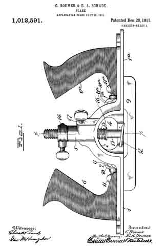
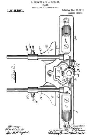
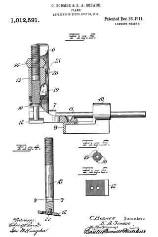
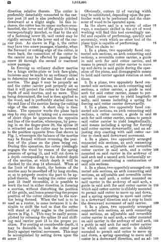
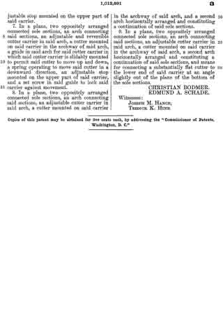
In the drawings Figure 1 is a side elevation of the plane. Fig. 2 is a plan view thereof. Fig. 3 is a section on the line x–x, Fig. 1. Fig. 4 is a side elevation of a detail. Fig. 5 is a section on the line y–y Fig. 4, looking up. Fig. 6 is a plan view of the cutter detached.

1–1a represent the two end sections of the sole of the plane.

2 is a connecting arch extending vertically from the plane of the sole sections 1–1a.

3 is a connecting arch extending horizontally from the sole sections 1–1a.

4 is a chip clearance passage between the arches 2–3.

5 is an upwardly extending tubular guide sleeve located above the arch 2.

6–6a are oppositely facing handles mounted on the two end sections 1–1a of the sole.

7–7a are bosses screw-threaded to receive horizontally extending guide rods 8–8a, when it is desired to use a gage.

9 represents a side gage having sleeves 10–10a arranged to slide upon the rods 8–8a respectively. The lower side of the arch 3 is smoothed off to form a continuation of the two sole sections 1–1a and to give a bearing of substantial width.

12 is a cutter connected to the lower end of an adjustable and slidable carrier post 13. This carrier post is mounted to slide up and down in the guide sleeve 5. The upper end of the carrier 13 is threaded and is provided with an adjustable stop 14 threaded thereon so that by rotating said stop, the downward projection of the carrier post 13 and cutter is limited.

15 is a spring arranged to press the carrier post 13 downwardly. In the preferred arrangement, this spring 15 is coiled around said post and rests at its upper end underneath the arch 2 and at its lower end against a washer 16, which may be rigidly connected to said post 13.

17 is a set screw which enters the guide sleeve 5 laterally, the inner end bearing against the carrier post 13 so that by setting up on said set-screw said post and cutter may be held against sliding movement up and down.

In the particular form shown, it will be seen that the side of the cutter carrier post 13 is provided with a plurality of longitudinal grooves 18–18.

19 is a spline carried by the guide 5, and in this instance hinged so as to be operated by a finger piece 20, said spline being suitably spring-pressed, as by a spring 21, to hold the spline projected into one of the grooves 18. In this instance, the spline and grooves are so placed that the cutting edge of the cutter 12 may be projected toward either end of the plane or laterally in either direction relative thereto. The cutter is preferably detachably connected to the carrier post 13 and is also preferably pitched downward at a slight angle. In this instance, the cutter has its upper surface cross-knurled, the lower end of the guide 13 being correspondingly knurled, so that by the aid of a fastening screw 22, said cutter may be rigidly secured to the lower end of the carrier post. As shown in Fig. 4, the cutter may have two screw passages, whereby, when the forward or cutting edge of the cutter, is worn back, the connection of the cutter to the carrier may be effected by passing the screw 22 through the second or rearmost screw passage.

In forming an ordinary shallow mortise for a hinge strike-plate or lock face-plate, incisions may be made by an ordinary chisel to determine merely the end lines of such a mortise. The gage 9 may be properly set and the cutter carrier post properly set so that it will project the cutter to the desired depth of said mortise, and no more. This being determined, the tool is then applied to the wood, and is preferably started close to the end line of the mortise facing the cutting edge of the cutter. A short chip is then taken. The operator works the plane back step by step until by taking out a succession of short chips he approaches the opposite end line of the mortise, whereupon, by pressing in on the finger-piece 20, the spline 19 is retracted and the cutter may be reversed to the position opposite from that shown in Fig. 1, whereupon the balance of the mortise may be formed without reversin the position of the plane on the piece being cut. During this operation, the cutter yieldingly engages the wood by reason of the spring pressure of spring 15, and will cut down to a depth corresponding to the desired depth of the mortise, at which depth it will be checked by the stop 14 aforesaid. When at the limit of this depth, the bottom of the mortise may be smoothed off by long strokes, so as to properly receive the part to be applied therein. By making the cutter carrier post 13 itself reversible, it is possible to work the tool in either direction in forming a mortise, without disturbing the position of the guide, and hence preserving the proper position of the cutter relatively to the mortise being formed. When the tool is to be used as a router, in some instances it is desirable to shift the tool so that the cutter will stand at right angles to the position shown in Fig. 1. This may be easily accomplished by releasing the spline 19 and shifting said carrier post 13 to the proper position. For routing at considerable depth, it may be desirable to lock the cutter post firmly against vertical movement. This may be accomplished by setting down upon the screw 17.

Obviously, cutters 12 of varying width may be substituted, depending upon the particular work to be performed and the character of wood to be operated upon.

In the above and in a variety of other ways, a mechanic skilled in the art of wood working will find this tool exceedingly useful and capable of performing, quickly and accurately, work which no other tool of the plane type is capable of performing.

What we claim is:

1. In a plane, two oppositely faced connected sole sections, an arch connecting said sections, a reversible cutter carrier, a guide in said arch for said cutter carrier, and means to permit said cutter carrier to move up and down in said guide during the operation of the plane, and disengageable means to hold said carrier against rotation at such times.

2. In a plane, two oppositely faced connected sole sections, an arch connecting said sections, a cutter carrier, a guide in said arch for said cutter carrier, means to permit said cutter carrier to yield longitudinally, said means including a spring for forcing said cutter carrier downwardly.

3. In a plane, two oppositely faced connected sole sections, an arch connecting said sections, a cutter carrier, a guide in said arch for said cutter carrier, means to permit said cutter carrier to yield longitudinally, said means including a spring for forcing said cutter carrier downwardly, and an adjusting stop coacting with said cutter carrier to check said downward movement.

4. In a plane, two oppositely arranged connected sole sections, an arch connecting said sections, an adjustable and reversible cutter carrier in said arch, and a cutter mounted on said carrier in the archway of said arch and a second arch horizontally arranged and constituting a continuation of said sole sections.

5. In a plane, two oppositely arranged connected sole sections, an arch connecting said sections, an adjustable and reversible cutter carrier in said arch, a cutter mounted on said carrier in the archway of said arch, a guide in said arch for said cutter carrier in which said cutter carrier is slidably mounted to permit said cutter to move up and down, and a spring operating to move said cutter in a downward direction and a stop to limit the downward movement of said carrier.

6. In a plane, two oppositely arranged connected sole sections, an arch connecting said sections, an adjustable and reversible cutter carrier in said arch, a cutter mounted on said carrier in the archway of said arch, a guide in said arch for said cutter carrier in which said cutter carrier is slidably mounted to permit said cutter to move up and down, a spring operating to move said cutter in a downward direction, and an adjustable stop mounted on the upper part of said carrier.

7. In a plane, two oppositely arranged connected sole sections, an arch connecting said sections, an adjustable and reversible cutter carrier in said arch, a cutter mounted on said carrier in the archway of said arch, a guide in said arch for said cutter carrier in which said cutter carrier is slidably mounted to permit said cutter to move up and down, a spring operating to move said cutter in a downward direction, an adjustable stop mounted on the upper part of said carrier, and a set screw in said guide to lock said carrier against movement.

8. In a plane, two oppositely arranged connected sole sections, an arch connecting said sections, an adjustable cutter carrier in said arch, a cutter mounted on said carrier in the archway of said arch, and a second arch horizontally arranged and constituting a continuation of said sole sections.

9. In a plane, two oppositely arranged connected sole sections, an arch connecting said sections, an adjustable cutter carrier in said arch, a cutter mounted on said carrier in the archway of said arch, a second arch horizontally arranged and constituting a continuation of said sole sections, and means for connecting a substantially flat cutter to the lower end of said carrier at an angle slightly out of the plane of the bottom of the sole sections.

CHRISTIAN BODMER.
EDMUND A. SCHADE.

Witnesses:
JOSEPH M. HANCE,
TREDICK K. HINE.

_________________

Copies of this patent may be obtained for five cents each, by addressing the “Commissioner of Patents, Washington, D. C.”
_________________

No. 992,392 – Woodworking-Tool (John Tucholski And Antoni Edmond Koziczenski) (1911)

[paiddownloads id=”679″]992392


UNITED STATES PATENT OFFICE.

_________________

JOHN TUCHOLSKI AND ANTONI EDMOND KOZICZENSKI, OF RACINE, WISCONSIN.

WOODWORKING-TOOL.

_________________

992,392. Specification of Letters Patent. Patented May 16, 1911.
Application filed April 30, 1910. Serial No. 558,576.

_________________

To all whom it may concern:

Be it known that we, JOHN TUCHOLSKI and ANTONI EDMOND KOZICZENSKI, both citizens of the United States, and residents of Racine, in the county of Racine and State of Wisconsin, have invented certain new and useful Improvements in Woodworking-Tools; and we do hereby declare that the following is a full, clear, and exact description thereof.

Our invention consists in what is herein particularly set forth with reference to the accompanying drawings and pointed out in the claim of this specification, its object being to provide simple, economical and efficient tools of the spoke-shave species designed to facilitate smoothing, rabbeting and molding work without injury to operators, as well as to provide for accurate gaging of width of cut in rabbeting and molding operations, whether said tools be drawn or pushed by their operators as the grain of the wood worked upon may require.

Figure 1 of the drawings represents a front elevation of a wood-working tool in accordance with our invention having a wedge clamping screw thereof partly broken away, and in this view the cutting of a rabbet is illustrated; Fig. 2, a plan view of the tool; Fig. 3, a similar view of the same reversed, and Fig. 4, a transverse section of said tool indicated by 4–4 in Fig. 2.

Referring by numerals to the drawings, 5 indicates the central stock, and 6 each of the oppositely extending handles of our improved tool said stock and handles being preferably cast together in one piece. The sole 7 is a central depending extension of the stock, whereby more than ordinary clearance is had under the handles, in order to prevent injury to the hands of an operator and to avoid marring of the work adjacent to a out of said tool, especially when the same is used upon curved work.

A longitudinal slot is provided in the forward portion of the stock through a depending flange 8 of the same, the under extremity of this flange being approximately flush with the sole, and said stock is provided with an angular bit and wedge opening such as is common in planes of various species. The bit 9, wedge 10 and clamp screws 11, 12 for the same herein shown, are also common in the art.

Matching the preferably beveled rear edge of the sole 7, we show hook-ends 13 of gage-bars 14, and each of these bars is provided with a socket-stud 15 that engages the slot 16 of the forward flanged portion of the tool-stock. The contour of each gage-bar stud and the tool-stock slot is such that there is wedging fit of one within the other, and a clamp-screw 17 is employed in engagement with said stud to draw and hold the same in said slot, the gage-bar being adjustable longitudinally of the sole (across which it extends) in proportion to the width of cut desired on the part of the bit in rabbeting or molding operations. By the employment of a pair of gage-bars, as is herein shown, adjusted equi-distant from the sides of the opposing sole, the tool may be drawn or pushed by an operator when cutting rabbets or moldings according as the grain of the wood worked upon is found to run one way or the other, said tool being turned about from time to time to change the cutting direction of its bit.

A straight edge bit being employed, as herein shown, the width of a rabbet may be accurately determined by an adjustment of one or both of the gage-bars 14, and the cutting of the rabbet can be more rapidly and accurately effected than is possible by chiseling. For smooth-work or wide molding, the gage-bars are omitted from the tool and said tool manipulated similar to those of the ordinary spoke-shave species, but to greater advantage because of the clearance afforded for the hands of the operator as above specified.

We claim:

In a woodworking tool of the spoke-shave species, the combination with its central stock having a forward depending and longitudinally slotted flange the under extremity of which is approximately flush with the sole of said stock, a gage-bar that crosses the aforesaid sole and has matching hook engagement with the same at the rear thereof, a socket-stud that extends from the gage-bar and has wedging fit with the slot of the stock-flange, and a clamp-screw engaging the stud.

In testimony that we claim the foregoing we have hereunto set our hands at Racine in the county of Racine and State of Wisconsin in the presence of two witnesses.

JOHN TUCHOLSKI.
ANTONI EDMOND KOZICZENSKI.

Witnesses:
CHRISTIAN JOHNSON,
MICHAEL OKOLEURKI.

_________________

Copies of this patent may be obtained for five cents each, by addressing the “Commissioner of Patents, Washington, D. C.”
_________________

No. 987,081 – Plane (Edmund A. Schade) (1911)

[paiddownloads id=”678″]987081


UNITED STATES PATENT OFFICE.

_________________

EDMUND A. SCHADE, OF NEW BRITAIN, CONNECTICUT, ASSIGNOR TO THE STANLEY RULE & LEVEL COMPANY, OF NEW BRITAIN, CONNECTICUT, A CORPORATION OF CONNECTICUT.

PLANE.

_________________

987,081. Specification of Letters Patent. Patented Mar. 14, 1911.
Application filed December 27, 1910. Serial No. 599,481.

_________________

To all whom it may concern:

Be it known that I, EDMUND A. SCHADE, a citizen of the United States, residing at New Britain, county of Hartford, State of Connecticut, have invented certain new and useful Improvements in Planes, of which the following is a full, clear, and exact description.

My invention relates to an improved frog adjustment for a bench plane, whereby the frog, which is the means for supporting the plane iron, may be readily adjusted to and fro, and which, when locked in position, is rigidly held in such a manner as to reduce to a minimum any chance of slippage or displacement.

In the drawings, Figure 1 is a longitudinal section of a plane showing my improved adjustment. Fig. 2 is a section on the plane of the line x–x, Fig. 1, looking from left to right. Figs. 3, 4 and 5 are detail views. Fig. 6 is a longitudinal section of part of a plane of slightly modified construction from that shown in Fig. 1, my invention being applied thereto. Fig. 7 is a cross section on the line y–y of Fig. 6, looking from right to left. Fig. 8 is a longitudinal section of a part of a plane of another modified form. Fig. 9 is a cross section on the line z–z Fig. 8, looking from left to right. Fig. 10 is a longitudinal section illustrating still another modification. Fig. 11 is a cross section thereof on the line w–w looking from right to left.

Referring to Figs. 1 to 5, 1 represents a sole of an iron bench-plane which may be, as to general details, of conventional form. 2 is a frog bearing, in this particular instance formed on an incline directly to the rear of the throat 3. 4 is a frog adjustably mounted on the support 2 for movement to and fro relatively to the throat 3. 5 is a plane iron. 6 is a cap of conventional form and by which the plane iron may be clamped to the frog 4. The invention in this case resides primarily in the means for adjustably securing the frog 4 to the frog support 2. In this instance the frog is provided with two longitudinal slots or passages 7 in which stand clamping or gripping studs 8–8. These studs are headed, the headed portions standing above the slots, the opposite ends projecting down into cavities or recesses in the support 2. Each stud is transversely recessed toward its lower end, as indicated at 9. 10 is what I will term a cam stud, there being one for each gripping stud 8. The cam studs are arranged in the support 2, suitable bores being provided therefor, the rear ends of said studs being arranged to receive a suitable tool, for example, a screw driver, the forward end of each cam stud being provided with an eccentric projection or cam 11. This cam 11 projects into the recess 9 of the respective gripping stud. 12 is a slot in the side of each cam stud. Entering from the side of the plane is a locking screw 14, the same being so arranged relatively to the slotted portion 11 of the cam stud that the forward ends of each screw 14 will engage the wall at the base of the recess 12 at one side of, or eccentric to, the axis of the cam stud.

In the operation of the parts thus far described, it will be seen that by rotating the cam stud in the proper direction, the cam 11 will engage with the wall at the lower end of the recess 9 in the gripping stud so that said gripping stud will be pulled down into firm gripping engagement with the frog 4. To give a further set to the cam and to guarantee against disengagement, the screw 14 may be turned in until its nose engages eccentrically said cam stud, tending to turn it in a direction to increase the tension of the cam on the gripping stud and also preventing any rotation of the cam stud in a reverse direction to release said gripping stud. I have found, by this means, that the frog may be very quickly and easily adjusted, and, at the same time, when locked in position, is held with exceeding rigidity.

In the other views I have shown slight modifications. For example, in Figs. 6 and 7 I have shown the frog 4a as mounted upon a support 2a having a two-point bearing for the frog. In this case as before, the frog is held by means of gripping studs 8a operated by cam studs 10a which are in turn controlled by screws 14a.

In Figs. 8 and 9 I have shown a modification in which instead of providing the gripping studs 8 for holding the frog to its seat, I have provided the frog 4b with a plate-like extension 8b which is preferably cast into the frog, so as to be a permanent part thereof, said plate 8b having passages to receve the cam ends 11b of the cam studs 10b. In this case, as previously, the side screws 14b may be employed to cooperate with the cam studs for the same purpose as before.

In Figs. 10 and 11 I have shown a modification more particularly of the construction shown in Fig. 8 in that instead of anchoring the aforesaid plate in the frog, I have anchored a similar plate in the frog support. In these views, 8c represents said plate anchored in the support 2c, and in this case the cam studs 10c are carried in passages in the rear of the frog 4c, the cam ends 11c engaging the walls of the slot in the plate 8c in the same manner as the cam ends 11b engage the walls of the slot in the plate 8b, shown in Figs. 8 and 9. Here again take-up screws are employed, the same being indicated at 14c. In this case the take-up screws are carried by threaded bores in the sides of the frog, suitable windows or clearance openings 15 being provided in the cheek pieces of the plane to permit a screw driver to be entered sufficiently to engage the slotted ends of said screws 14c for the purpose of operating the same.

In both forms of devices shown in Figs. 8 to 11, a suitable clearance space is provided for the plates 8b and 8c respectively whereby there may be a relative movement between said plate and the part carrying the cam screw. In these cases, the cam ends 11b and 11c respectively should be of sufficient length to engage the plates 8b and 8c respectively in all of the various positions of adjustment.

What I claim is:

1. In a plane, a main body portion having a throat therein, a frog support at the rear of said throat, a frog adjustable to and fro thereon, a locking means for holding said frog in different positions of adjustment comprising a clamping member operatively engaged with one of said parts, means for operating said clamping member carried by the other part and comprising a rearwardly projecting cam stud coacting with said clamping member, and a lock and tightener for said cam stud, said lock and tightener comprising a laterally projecting exposed screw engaging said cam stud in a direction to turn the same as said lock and tightener is advanced.

2. In a plane, a main body portion having a throat therein, a frog support at the rear of said throat, a frog adjustable to and fro thereon, a locking means for holding said frog in different positions of adjustment comprising a clamping member operatively engaged with one of said parts, means for operating said clamping member carried by the other part and comprising a rearwardly projecting cam stud coacting with said clamping member, a lock for said cam stud, said lock comprising a laterally projecting exposed screw, and a shoulder on one side of said cam stud eccentric thereto, said screw engaging said eccentric shoulder and pressing against the same in a direction to turn said cam stud so as to more tightly engage the clamping member.

3. In a plane, a body portion having a throat, a frog support at the rear of said throat, a frog adjustable to and fro on said support and relatively to said throat, a clamping member carried by said frog and projecting into said support, said support having a recess therefor, a cam stud carried in said support and exposed at its rear end, an eccentric pin extension at the forward end of said stud eccentrically engaging said clamping member, and a lock screw for engaging said clamping stud at one side and arranged laterally thereto.

4. In a plane, a body portion having a throat, a frog support at the rear of the throat, a frog mounted for adjustment to and fro on said support, said frog having a fore and aft slot therein, a clamping stud passing downwardly through said slot into said support, an operating device for said clamping stud comprising a cam stud mounted in said support, an eccentric pin projection at the forward end of said cam stud eccentrically engaged with said clamping stud, and a lock for said cam stud.

5. In a plane, a body portion having a throat, a frog support at the rear of the throat, a frog mounted for adjustment to and fro on said support, said frog having a fore and aft slot therein, a clamping stud passing downwardly through said slot into said support, an operating device for said clamping stud comprising a cam stud mounted in said support, an eccentric pin projection at the forward end of said cam stud eccentrically engaged with said clamping stud, and a lock for said cam stud, said lock comprising a screw entering said frog support from the side of the plane.

6. In a plane, a body portion having a throat, a frog support at the rear of the throat, a frog mounted for adjustment to and fro on said support, said frog having a fore and aft slot therein, a clamping stud passing downwardly through said slot into said support, an operating device for said clamping stud comprising a cam stud mounted in said support and eccentrically engaged with said clamping stud, and a lock for said cam stud, said lock comprising a screw entering said frog support from the side of the plane, said screw engaging said cam stud eccentrically to rotate the same in a direction to increase the pressure on the clamping stud.

EDMUND A. SCHADE.

Witnesses:
W. J. WORAM,
H. S. WALTER.

_________________

Copies of this patent may be obtained for five cents each, by addressing the “Commissioner of Patents, Washington, D. C.”
_________________

No. 984,610 – Dado-Plane (Henry Smiley) (1911)

[paiddownloads id=”677″]984610


UNITED STATES PATENT OFFICE.

_________________

HENRY SMILEY, OF BOSTON, MASSACHUSETTS.

DADO-PLANE.

_________________

984,610. Specification of Letters Patent. Patented Feb. 21, 1911.
Application filed November 30, 1909. Serial No. 530,706.

_________________

To all whom it may concern:

Be it known that I, HENRY SMILEY, a citizen of the United States, residing at the city of Boston, in the county of Suffolk and Commonwealth of Massachusetts, have invented certain new and useful Improvements in Dado-Planes, of which the following is a specification.

This invention relates to that class of groove cutting planes usually termed dado planes, and it has for its object the effecting of the improvements in details of construction hereinafter set forth.

Referring to the drawings forming part of this specification, Figure 1 is a side view of a plane made in accordance with my invention. Fig. 2 is a side view of the metallic part thereof, the wooden section forming part thereof being represented as removed. Fig. 3 is an edge view of the plane from beneath. Fig. 3a is an end view of the blade-engaging block. Fig. 3b is an end view of the blade-wedge. Fig. 4 is a transverse section on the dotted line X–X in Fig. 1; this and the following views being on a slightly larger scale than the preceding. Fig. 5 is a transverse section on the dotted line Y–Y in Fig. 1. Fig. 6 is a longitudinal vertical section of a part of the plane showing the gage for permitting adjustment of the depth to which the plane can cut. Fig. 7 is a similar view but from the opposite side. Fig. 8 is a side elevation of a portion of the plane from a point opposite to that from which Fig. 1 is taken. Fig. 9 is a transverse sectional view of the plane through the center of the grooving cutters. Fig. 10 is a perspective view of said grooving cutters. Fig. 11 is a face view of the cutting blade of the plane. Fig. 12 is a face view of one of the U-shaped locking devices.

The plane comprises two main parts, one of metal containing the operating members, and the other of wood or the like inclosing said members at one side and having the handle 1. Said metallic portion consists of the thin plate 3 from which rise certain ribs and also the bosses 4 into which are tapped the screws 5 by means of which said wooden part 6 is secured to said metallic part.

The blade 7, shown in Figs. 2 and 11, rests against the rib-section 8 and also against the adjusting block 9, being made to share the longitudinal movement of the latter by means of one of its transverse grooves 10 into which projects the rib 11 of said block. This block is moved along the surface of the inclined rib 12 by means of the adjusting screw 13; the latter being turned by its head 14, and held against longitudinal displacement by bearing 15 and the U-shaped locking device 16 located in a transverse slot in said bearing and engaging an annular groove 17 in the screw. Fig. 12 shows this locking device in face view, while Fig. 9 shows a duplicate of the same in section. Above the cutting edge of said blade 7 is a shaving-deflector mouth 18, which, as shown in Figs. 1, 2 and 3, is so conformed as to perfectly eject all the shavings ploughed up by said blade. As indicated by Fig. 1, said mouth is substantially horse-shoe shaped vertically, while, as in Fig. 3 it is trumpet shaped laterally, thereby performing the function above set forth. Said blade is clamped in place by the vertically moved triangular block 19, the means for its movement being the thumb-screw 20 turning in the bearing 21 and held from longitudinal displacementby the U-shaped lock 16a, a duplicate of that illustrated by Fig. 12. As shown in Fig. 2, the nose of this clamping block 19 comes quite close to the cutting end of the blade 7, and the entire length, nearly, of said blade is so tightly pressed by said block as to firmly hold it against all possibility of displacement or chattering. The vertical face or edge of this block abuts against the end of the rib 22 in order that there may be no lateral strain on the thumb screw 20, but have for its only function that of raising and lowering said block. To keep the cutting edge of said blade 7 flush with the metallic face of the plane and still leave the plate 3 intact, said blade is off-set somewhat, as shown in Fig. 11, and a part of said plate cut into as shown in Fig 8 to make room for the offset shoulder 23. To remove the blade for resharpening, the thumb screw 20 is turned to raise the block 19 a short distance, and then the screw 13 turned until the blade is carried far enough downward to bring its shoulder 23 out from beneath the lip 24. The blade can now be moved laterally out of its engagement with the rib 11 of the block 9, and then longitudinally withdrawn from the plane. Its return is in the reverse manner.

It is customary to provide these dado planes with cutters in advance of the blades for the purpose of scoring the lateral limits of the groove being plowed in the wood, in order that the shavings may be cut by the blade clear and clean from the wood, leaving the groove smooth and exact. There are numerous objections to those now in use, which I have overcome by my construction. Previous to my invention, the cutter points have been two in number, one at each side of the plane. I have found, however, that a plurality of these cutter points at each side give much better results, and consequently I provide a vertically adjustable bar 25 with four such points 26, two at a side, as shown in Figs. 2, 9 and 10. In the formation of these cutter points, not only is the metal of the bar cut away both laterally and longitudinally with respect to the plane, in order to leave such points in operative relief, but I form channels 27 in the opposite sides of the bar in order to provide cutting lateral edges. These edges 28 are sharpened by a suitable file which can under-cut the same slightly. The cutter points are lowered to take up for sharpening, and also rigidly held in place, by means of the adjusting screw 30 and the set screw 31 (Fig. 4), the former screw being held by its bearing 32 and locking device 16b like the one 16 already described. As shown in Fig. 9, this bar has also to be off-set, for the same reason as the blade 7.

Normally the dado plane can cut to the depth permitted by the under surface of the wooden section 2. To permit accurately gaged grooves of lesser depth to be formed, I provide the adjustable stop 33 shown in Figs. 3, 6 and 7. This is cut into the wooden section 6, and is adjusted by means of the screw 34 turning in the boss 35 and tapped into the boss 36 of the plate 37 which is fixed in place by suitable screws 38. Said screw 34 being kept from displacement in its boss 35 by a locking device 16c such as already described, is adjusted either down to desired specified point, or carried up to its normal flush position, by suitably rotating said screw. Said fixed plate 37 is formed with a circular boss 39 (Figs. 4 and 7) for receiving the set screw 31 already described; said boss extending out flush with the wooden section 6, and so providing said set screw with a metallic threaded member for its proper support. Thus made, this dado plane is strong, durable; its operative members are readily adjusted, cut clean and smooth, and in every way performs its work well and conveniently. It should be noticed that the cutter points 26 are each substantially like those of a saw tooth, being angular and having cutting edges both in front and behind. This enables them to cut and score the wood both when the plane is being advanced, and when it is being drawn backward, thus more perfectly preparing the way for the blade 7 to do its work. Moreover, the cutting edges 28 above described act to smooth the sides of the groove being planed.

It will be observed that by having the angular block 11 formed with a vertical face coming down sharply to the upper surface of the blade 7, there is no opportunity given for the lodgment of shavings against the same; hence, taking this in connection with the peculiar conformation of the mouth 18, there can be no choking at the cutting edge of said blade, and consequently no vexatious loss of time in digging out such accumulated chips.

As shown in Figs. 4, and 9, the U-shaped locking devices 16, 16a, 16b, 16c are held in place by the wooden section 6 fastened over the metallic section, and consequently all that requires to be done in order to take the various screws 13, 20, 30 and 34 out, is to first remove said wooden section, then pry out said U-shaped devices and unscrew said members. To keep the fastening screws 5 from digging into the wooden section 6, I prefer to provide therefor the metallic thimbles 40, shown in Figs. 1 and 5, the outer edges of which are fiush with the face of said section, and which receive the heads of said screws flush with the same also.

It is essential that the surface of the mouth 18 opposite the blade 7 shall be made to initiate in the shaving a spiral form as it leaves the edge of said blade. To accomplish this, I form said surface 18a with a twist in such a manner that the rear edge of the mouth will retire behind the front edge at 18b, as shown in Figs. 1 and 2. This twist extends upward from the blade edge for about five eighths of an inch; after that it being merged into the trumpet flare above described.

As shown in Fig. 3b, the block 9 is given a slightly oblique face on its side lying against the surface of the blade 7, inasmuch as the latter is laterally inclined in order to better cut the wood being grooved. In the same way, the wedge 19 must have its face lying against the blade similarly oblique, as shown in Fig. 3a.

What I claim as my invention and for which I desire Letters Patent is as follows, to wit;

1. The combination with a dado plane, of cutter points therefor comprising a metal bar having its end fashioned into four saw-shaped points, each pair of points on the faces of the bar parallel with the sides of the plane being separated a substantial distance one from the other by a vertical clearance channel extending up toward the upper end of said bar, the sides of said channels presenting cutting edges.

2. A dado plane comprising two parts one of which is metal and is formed with two vertical parallel walls, a cutter point bar fitted to said walls, the other of said two parts being of wood and inclosing said bar, a metal plate fitted to the inner surface of said wooden part and having a cylindrical boss passing through said wooden part to its outer surface, and a set screw tapped through said boss and butting against said bar.

3. The combination in a dado plane, of a metallic section, a cutter-point member carried thereby, a screw for the adjustment of said member having an annular groove therein, a bearing for said screw formed with a transverse slot, a U-shaped locking device located in said slot and engaging said groove, and a section fastened to the metallic section and retaining said locking device in place.

In testimony that I claim the foregoing invention, I have hereunto set my hand this 13 day of November, 1909.

HENRY SMILEY.

Witnesses:
A. B. UPHAM,
H. L. WHITTLESEY.

No. 984,083 – Floor-Plane (William J. Faber) (1911)

[paiddownloads id=”676″]984083


UNITED STATES PATENT OFFICE.

_________________

WILLIAM J. FABER, OF ONEIDA, NEW YORK.

FLOOR-PLANE.

_________________

984,083. Specification of Letters Patent. Patented Feb. 14, 1911.
Application filed March 28, 1910. Serial No. 551,829.

_________________

To all whom it may concern:

Be it known that I, WILLIAM J. FABER, of Oneida, in the county of Madison, in the State of New York, have invented new and useful Improvements in Floor-Planes, of which the following, taken in connection with the accompanying drawings, is a full, clear, and exact description.

This invention relates to certain improvements in floor planes for smoothing floors and other wood surfaces.

ln the use of ordinary planes the cutting blade is previously set or adjusted to produce the desired depth of cut and remains in this position until readjusted to vary the depth of the cut and under such conditions, preferably in smoothing the surface of hard wood, it is extremely difficult to start the plane on its initial movement owing to the fact that immediately upon the beginning of such movement the cutting edge is embedded to the full depth of its adjustment into the wood, thereby requiring considerable power to move the plane forward. Furthermore under the same conditions when the plane is drawn backward, the cutting edge is allowed to drag or ride over the surface of the floor, thereby producing excessive wear and more or less dulling effect upon such edge, and making it necessary to frequently regrind or re-sharpen the same.

The main object of my present invention is to provide means whereby the cutting edge of the blade will be held clear of the surface of the floor during the initial forward movement and will be gradually forced to its cutting position as the plane advances, thereby enabling the operator to move the plane forwardly under comparatively light pressure or force or until under sufficient momentum to permit the plane to be carried to the limit of its forward stroke with a minimum amount of power. In other words, the object sought is to cause the cutting edge of the blade to automatically clear the surface of the floor during the backward stroke and to be gradually moved to its cutting position during the forward stroke, so as to allow the plane to be moved through the complete forward stroke with a minimum degree of power and at the same time relieving the cutting edge from undue wear during the backward stroke.

Other objects and uses relating to specific parts of the device will be brought out in the following description.

In the drawings: Figure 1 is longitudinal sectional view of a plane embodying the various features of my invention. Fig. 2 is an inverted plan of the same. Fig. 3 is a transverse sectional view taken on line 3-3-, Fig. 2.

This plane comprises a base section –1– and a stop section –2– resting upon and movable relatively to the base section. The meeting faces of said sections are inclined rearwardly from the front end and are therefore disposed at an angle with the bottom of the base section –1– which is substantially flat. The object of the inclined meeting faces is to permit a slight vertical movement of the section –2– as the plane is moved forward and backward. The upper section –2– is adapted to be engaged by the hand of the operator and it therefore follows that during the operation of moving the plane forward the upper section will be moved down the incline or slightly lowered, while the backward movement will similarly elevate the top section. These sections –1– and –2– are limited in their relative endwise movement by suitable stops –3– consisting in this instance of bosses which are projected into elongated slots –4– near the front and rear ends respectively of the base section –1– and formed with threaded apertures in the under side of the top section –2–. The slots –4– are enlarged at the bottom to receive the heads of screws –3’– and to form shoulders against which said heads abut to hold the meeting faces of the sections –1– and –2– in sliding contact, the heads of the screws being wholly within the lower surface of the section –1– to prevent contact with the surface which is being planed. This lower section –1– is also provided with a comparatively narrow knife opening –5– through which the cutting edge of a knife blade, as –6–, is movable and adapted to protrude when in operative position, the lower surface of the section –1– just back of the cutting blade being reinforced by a metal plate –7–. The cutting blade –6– is adjustably mounted in and upon the upper section –2– where it is locked or held in its adjusted position by a set screw –8– or other suitable fastening means, not necessary to further illustrate or describe, it being understood that any well known fastening means common in this art may be employed for this purpose which will enable the blade to be adjusted so that its cutting edge protrudes more or lesss through the opening –5–.

The plane is operated back and forth by the engagement of one or both hands of the operator upon the upper section –2– and owing to the fact that this section is movable relatively to the lower section –1– it is apparent that as the plane is drawn back the upper section will be moved up the incline of the lower section a distance corresponding to the length of the slots –4– or until limited by the engagement of the limiting stops with the rear ends of the slots thereby elevating the cutting edge of the blade –6– above the lower face of the plane section –1– whereupon the continued backward movement of the upper section of the plane effects a corresponding backward movement of the lower section –1–, as soon as the limiting stops –3– engage the rear ends of the slots –4–, it being understood that when the cutting blade is in its lowermost position the protrusion of its cutting edge will not exceed the degree of rise of the incline for the length of the slot. In moving the plane forward for the cutting operation assuming that the upper section is then in its extreme backward position or at the highest point of incline, the upper section will be initially or first moved down the incline and relatively to the lower section until the cutting edge of the blade is brought into engagement with the surface to be planed or until the limiting stops –3– engage the front ends of the slots –4– whereupon both sections will be moved forwardly together. This initial movement of the upper section –2– relatively to the lower section –1– requires but little strength or force and enables the operator to get the plane under head-way or momentum before the cutting edge of the blade is embedded to its maximum degree of adjustment into the wood and therefore this momentum aids the operator in forcing the plane through its forward stroke during the cutting operation, thereby reducing the power required to operate the plane from one extreme to the other of its cutting stroke. Another advantage is that when the plane is drawn back by means of the upper section –2– which rides upwardly along the incline of the lower section, the blade is withdrawn from the face of the lower section thereby avoiding excessive wear or rounding of the cutting edge.

In order that the section –2– may be guided longitudinally of and parallel with the lower section –1–, I provide the meeting faces of said sections with one or more tongues –9– and corresponding grooves –10– interfitting with each other, although the limiting stops –3– playing in the grooves –4– perform a similar function.

The operation of my invention will now be readily understood upon reference to the foregoing description and accompanying drawings and though I have shown a specific mechanism for adjusting and clamping the cutting blade and specific form of stops for limiting the relative endwise movement of the plane sections, I do not wish to limit myself to any particular form of construction of either one of these mechanisms, nor to the exact means for moving the cutting blade into and out of the opening –5– or above or below the lower face of the lower section, further than it must be some means whereby the blade is elevated on the backward movement of the upper section and lowered to its cutting position upon the forward movement of the same section.

What I claim is:

1. In a hand operated plane, two frame sections mounted one upon the other and having their meeting faces inclined longitudinally from front to rear, a cutting blade adjustably mounted on the upper section and having its lower edge protruding through the bottom of the lower section when in its cutting position, the upper section being movable endwise relatively to the lower section whereby the cutting blade is raised and lowered as the upper section is moved backward and forward, and means for limiting such movement.

2. In a floor plane, two frame sections mounted one upon the other, the upper face of the lower section being inclined from front to rear and the upper section resting upon and movable along said inclined face, a cutting blade mounted upon the upper section and protruding through the bottom of the lower section when in its cutting position, and means for limiting the movement of the upper section relatively to the lower section.

3. In a floor plane, two frame sections mounted one upon the other and having inclined meeting faces in sliding contact, a cutting blade adjustably mounted upon the upper section and having its cutting edge movable to and from a position below the bottom face of the lower section as the upper section is moved forward and backward, and means for limiting such movement.

In witness whereof I have hereunto set my hand on this 19th day of March 1910.

WILLIAM J. FABER.

Witnesses:
HARRY H. JACOBS,
JAMES E. BREWER.