No. 1,331,280 – Carpenter’s Plane (Edmund A. Schade) (1920)

[paiddownloads id=”724″]1331280


UNITED STATES PATENT OFFICE.

_________________

EDMUND A. SCHADE, OF NEW BRITAIN, CONNECTICUT, ASSIGNOR TO THE STANLEY RULE &
LEVEL COMPANY, OF NEW BRITAIN, CONNECTICUT, A CORPORATION OF CONNECTICUT.

CARPENTER’ S PLANE.

_________________

1,331,280. Specification of Letters Patent. Patented Feb. 17, 1920.
Application filed November 6, 1919. Serial No. 336,122.

_________________

To all whom it may concern:

Be it known that I, EDMUND A. SCHADE, a citizen of the United States of America, residing at New Britain, Connecticut, have invented new and useful Carpenters’ Planes, of which the following is a specification.

The main object of my invention is to provide a simple, rigid construction in which the blade is so supported that it may be readily adjusted to vary the cutting depth and yet so that the blade may be readily removed and replaced in its proper position without changing the adjustment. Another object is to maintain the parallelism of the cutting edge of the cutter when adjusting the depth of cut.

In its preferred form the body of the plane is of metal and provided with a guide frame rigidly secured to the body. The cutter is provided with a detachable clamp block by means of which it is guided in the frame. The adjustment is effected by a screw coacting with the guide frame and the clamp block. A cap member holds the cutter in position.

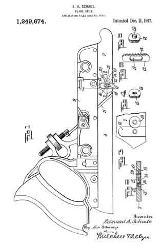
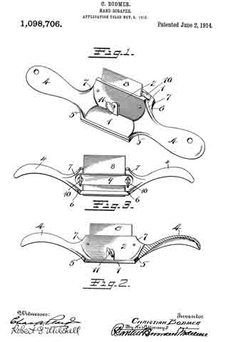
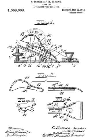
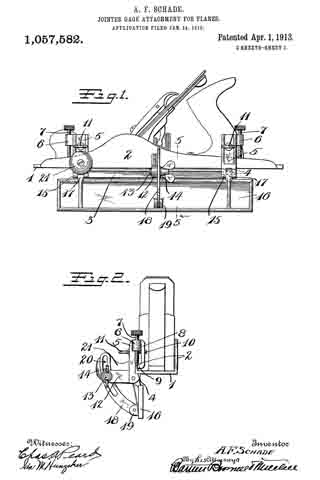
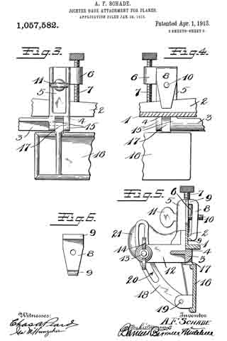
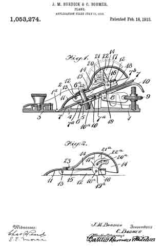
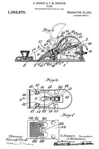
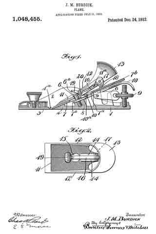
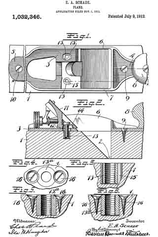
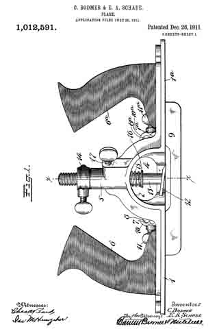
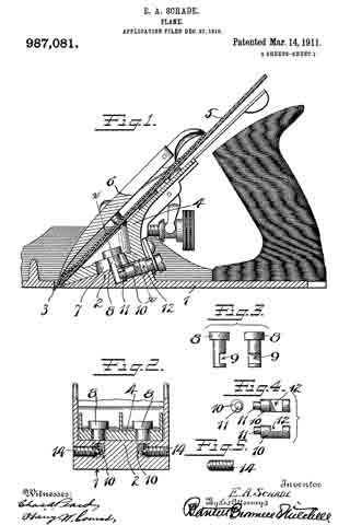
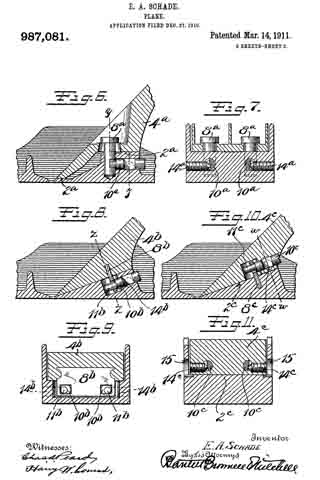
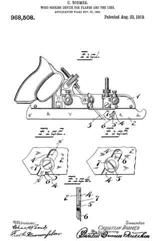
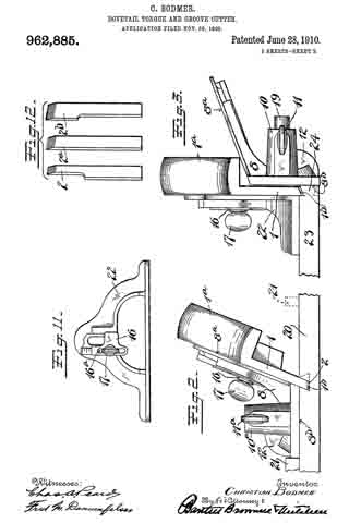
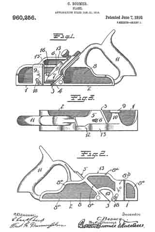
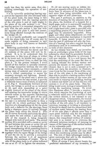
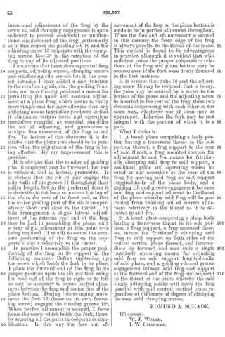
Figure 1, is a side view of a plane embodying the improvements of my invention.

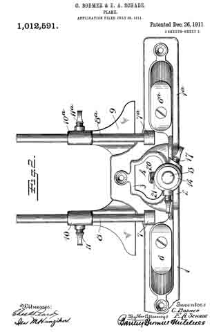
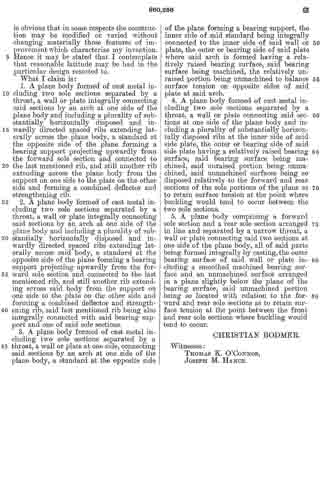
Fig. 2, is a longitudinal sectional view on the plane of the line 2–2 of Fig. 3 on a larger scale than Fig. 1.

Fig. 3, is a transverse sectional view on the plane of the line 3–3 of Fig. 2.

Fig. 4, is a fragmentary plan view of the parts of the body of the plane embodying my improvements.

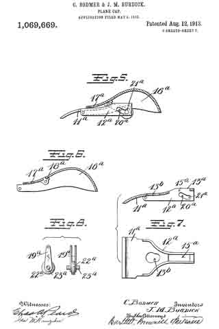
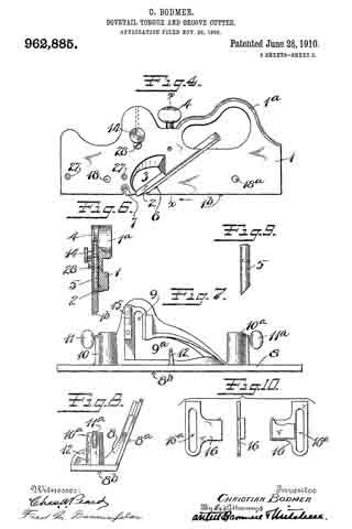
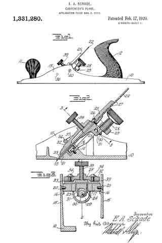
Fig. 5, is a detail plan view of the guide frame, detached.

Fig. 6, is a detail view showing the underside of the cutter and the clamp block.

Fig. 7, is a plan view of a cap member.

Fig. 8, is a bottom view of the cap member.

The body 10 of the plane is preferably of metal and in the form shown is provided with a front handle 11 and a rear handle 12. Just in rear of the slot or throat 13, is located an inclined seat 14 between the side flanges 15, 15. Above and to the rear of this seat are seats 16, 16. On these seats 14 and 16 is mounted the guide frame 17, the lower end of which rests on the seat 14 by which it is secured for instance, by means of a screw 18, the head of which is in the recess 19. The sides of this frame 17 are secured to the seats 16, 16 of the body by suitable rivets or screws such as 20, 20, so that the guide frame 17 is rigidly held in place braced between the seat 14 above the sole of the plane and the side flanges 15, 15. Below the guide frame the plane is provided with an inclined seat 21 which forms a continuation of the inclined upper face of the guide frame 17 for supporting the cutter 22.

Attached to the cutter is a block 23 adapted to slide up and down in the opening 24 in the guide frame 17. This block is secured to the cutter by means of an upper piece 25 and the screw 26 which passes through one of the slots such as 27 in the cutter. A thumbscrew 28 which has a threaded engagement with a lug 29 of the guide frame 17 has a grooved tip 30 which engages a forked part 31 on the block 23, so that by rotating the thumbscrew 28 the block 23 and cutter 22 may be adjusted up and down on the inclined seat formed by the guide frame 17 and the part 21 of the body of the plane.

The detachable cap is made up of the two parts 32 and 33 held together by screws such as 34 passing through the slots such as 35. A cross rod 36 connects the two sides of the plane just above the cutter and spaced apart from it sufliciently to permit of introduction of the cap member. The cap member is provided with a shoulder 37 adapted to limit the downward movement of the cap member. The under side of the cap member is recessed at 38 to allow for the clamp piece 25. A thumb screw 39 is adjustable through the cap member for clamping the parts tightly in place.

To remove the cutter it is simply necessary to retract the screw 39, lift out the cap member, whereupon the cutter and the block 23 may be lifted out without affecting the adjustment of the screw 28. To replace the cutter is simply necessary to insert its lower end below the cross rod 36 and drop the forked part 31 of the block 23 over the lower end of the adjusting screw 28, which brings the cutter into exactly the same position which it was before.

It is to be noted that the guide frame which carries the adjusting screw 28 is supported from the sole and side flanges by means of three securing elements 18, 20, 20 thus giving a rigid three point support and insuring against danger of the parts becoming displaced either accidentally or through wear. These seats being relatively small and projecting from the adjacent metal of the body can be readily and accurately finished.

I claim :–

1. A plane comprising a body having a sole and side flanges, a guide frame fitted between said flanges, means passing through said frame at the lower end rigidly securing said frame to said sole, and means passing through said flanges and into said frame for rigidly securing the upper part of said frame to said flanges.

2. A plane comprising a sole and side flanges projecting upwardly from the sole, a guide frame secured near one end to said sole and at another portion to one side flange.

3. In a plane having a sole and side flanges projecting upwardly from said sole, a guide frame secured to said sole and to the side flanges for securing a rigid three point support for the guide frame in the plane body.

4. ln a plane having a sole and side flanges projecting upwardly from said sole, a guide frame between said side flanges, and means passing through said side flanges and into said guide frame for securing the latter in place.

EDMUND A. SCHADE.

No. 1,249,674 – Plane-Spur (Edmund A. Schade) (1917)

[paiddownloads id=”719″]1249674


UNITED STATES PATENT OFFICE.

_________________

EDMUND A. SCHADE, OF NEW BRITAIN, CONNECTICUT, ASSIGNOR TO THE STANLEY RULE & LEVEL CO.,
OF NEW BRITAIN, CONNECTICUT, A CORPORATION OF CONNECTICUT.

PLANE-SPUR.

_________________

1,249,674. Specification of Letters Patent. Patented Dec. 11. 1917.
Application filed June 18, 1917. Serial No. 175,271.

_________________

To all whom it may concern:

Be it known that l, EDMUND A. SCHADE, a citizen of the United States of America, residing at New Britain, Connecticut, have invented a new and nuseful Plane-Spur, or which the following is a specification.

My present invention relates to planes and the general objects of the invention are to provide an improved and more efficient spur construction for rabbet, dado and other planes or similar type.

A special object is to rnaintain the setting or adjustment or the spar with respect to the cutting blade.

ln accomplishing the foregoing, I construct the plane stock with teeth projecting into the spur receiving channel and the spur is constructed with teeth to engage and mesh with the teeth on the stock, these teeth being disposed so as to resist the strain exerted on the spur and to thereby rnaintain the spur in its adjusted position. Usually the teeth on the steel are provided hy a hard metal insert seated in the body out the stock.

The accompanying drawing illustrates the invention embodied in a practical and preferred form, but it will be understood that changes and modifications may be made without departing from the true spirit and scope of the invention.

ln the drawing:

Figure 1 is a view in side elevation of a “Stanley Universal” plane having rny invention incorporated therein.

Fig. 2 is a horizontal sectional view taken through the spar construction substantially on the plane of the line 2–2 of Fig. 1.

Fig 3 is a fragmentary view of that portion of the plane stock in which the spur receiving channel and the recess for the anchoring element are formed.

Fig. 4 is a detail perspective view or the so-called anchoring element.

Fig, 5 is a detail perspective view of the spur.

Fig. 6 is a similar view of a modfied form of anchoring element.

The stock or the plane in the case illustrated is formed in front and rear sections 7 and 8 respectively, attached to a back or body member 9, said sections being separated by an angular opening or throat 10 through which the cutter blade 11 projects.

12 designates the spur, located in advance of the cutter and disposed in a channel or seat 13 formed in the side of the front stock section 7. This channel preferably extends substantially at right angles to the cutting plane of the tool, permitting of an up and down adjustment or the spur in the channel for the purpose of setting the spur with respect to the cutter blade, it being understood that the lower cuttiing edge of the spur is usually set slightly below the cutting edge or the blade so as to score the material in advance of the blade.

The spur is locked in its adjusted position in my invention, by providing it on the forward edge thereof with teeth or serrations 14 for engagement with corresponding teeth or serrations 15 on the stock, the spur being held seated in its channel and engaged with the teeth aforesaid by rneans such as a screw 16 extending through a slot 17 in the spur into engagement with a screw seat in the stock at the back or the channel. These interlocking teeth on the stock and spur are disposed in planes substantially parallel to the cutting plane and transversely with respect to the longitudinal adjustment of the spur so as to resist the strain on the spur when the plane is in use.

The teeth on the stock are provicled in the case illustrated by a hard metal disk or washer 18 in the nature of an “insert”, seated in a recess 19 at one side of and opening into the edge portion of the spur receiving channel, this disk having a flattened toothed edge portion projection into the edge part of the channel. The locking or anchor disk 18 may be secured in planes in various ways as by welding or riveting, it being shown in the present instance as held in its seat by a rivet 20. ln Fig. 6 the rivet is shown formed integral with the disk rnember.

This invention rnakes it possible to set the spur to the proper depth with respect to the cutter and to maintain that relation during the subsequent use of the tool and at the same time, it is possible as the cutting edge of the spur wears down, to easily set the spur to at new adjustment or when desirable, to change the position of the spur for cutting in softer or harder woods.

l claim :

1. ln a plane, a stock having a spur receiving channel in one side thereof, a recess in said stock at one side of said channel and opening into the edge of said channel, a hard metal locking device fixed in said recess and having a toothed edge at one side projecting into the side edge of the channel aforesaid, a spur having one edge toothed to coact with the teeth on said locking portion, the width of said spur corresponding to the width of said channel, said spur being adjustably engaged with said locking device by a lateral movement of said spur whereby the degree of projection of said spur below said stock may be controlled, and means for holding said spur against lateral disengagement from said locking device when the latter is in its adjusted operative position.

2. In a plane, a stock having a spur receiving channel in one side thereof, a recess in said stock at one side of said channel and opening into the edge of said channel, a hard metal locking device fixed in said recess and having a toothed edge at one side projecting into the side edge of the channel aforesaid, a spur having one edge toothed to coact with the teeth on said locking portion, the width of said spur corresponding to the width of said channel, said spur being adjustably engaged with said locking device by a lateral movement of said spur whereby the degree of projection of said spur below said stock may be controlled, and means for holding said spur against lateral disengagement from said locking device when the latter is in its adjusted operative position, said holding means comprising a screw passing through a longitudinal slot in said spur and screwing into said stock.

EDMUND A. SCHADE.

_________________

Copies of this patent may be obtained for five cents each, by addressing the “Commissioner of Patents, Washington, D. C.”
_________________

No. 1,201,433 – Plane (Christian Bodmer) (1916)

[paiddownloads id=”714″]1201433


UNITED STATES PATENT OFFICE.

_________________

CHRISTIAN BODIVIER, OF NEW BRITAIN, CONNECTICUT, ASSIGNOR TO THE STANLEY RULE
AND LEVEL COMPANY, OF NEW BRITAIN, CONNECTICUT, A CORPORATION OF CONNECTICUT.

PLANE.

_________________

1,201,433. Specification of Letters Patent. Patented Oct. 17, 1916.
Application filed June 2, 1916. Serial No. 101,233.

_________________

To all whom it may concern:

Be it known that I, CHRISTIAN BODMER, a citizen of the United States of America, residing at New Britain, Connecticut, have invented a new and useful Plane, of which the following is a specification.

My present invention relates to planes and has for its general objects to provide a practical and inexpensive form of plane which can be used for a number of purposes and which will therefore take the place of a plurality of planes usually employed for such special purposes.

Other objects are to increase the solidity and strength of the same and to make it easily regulatable or adjustable to meet the different conditions.

In the accomplishment of the foregoing and other objects I construct a plane in two parts and mount the cutter blade on the forward end of the rearward section so that when the front part or section is removed the cutter will be left exposed and therefore adapt the rearward section for working in corners, etc. The two sections are rigidly united but so as to permit quick separation of the parts.

A special feature of the invention is the provision of a handle arch on one of the members having a seat or platform with which the other member is engaged, said arch being of reduced width at a point above the cutter seat to accommodate the shank of a cutter and a shank and a cap which has bearing against the under side of the arch.

Other features and details of construction will appear as the specification proceeds.

In the accompanying drawing I have illustrated my invention embodied in a concrete and practical form but it will be understood that changes and modifications may be made without departing from the true spirit and scope of the invention.

In this drawing: Figure 1 is a perspective view of a plane constructed in accordance with and embodying the invention. Fig. 2 is a broken plan view of the same. Fig. 3 is a broken side view of the rear or main body section of the plane.

Referring to the drawing more in detail: 7 designates the rearward main body portion of the plane and 8 designates the forward member or section of the plane, said sections being shown as having plain under surfaces 9 alining to form the bottom of the plane and plain side faces 10 disposed at right angles to the bottom. The two body members are rigidly secured together in a manner to permit of their ready separation by providing a rearward section having a platform 11 on its opposite end to receive a rearwardly projecting lug or supporting portion 12 on the forward section, relative lateral movement of the two members being avoided by providing the forward section with shoulders 13 at the opposite ends of the supporting lug arranged to bear against shoulders 14 at the opposite ends of the platform on the rear member, a single screw 15 sufficing with this construction to rigidly and positively secure the two parts together.

The rearward section is made preferably with an arch 16 extending rearwardly and downwardly from the platform to constitute a handle and guard for parts housed therein and this arch is preferably reduced in width at 17 at a point below the platform to provide clearance for the cutter and the cutter holding cap.

The cutter is designated 18, the same being shown in the form of a blade supported on an inclined seat 19 on the forward end of the rearward plane section, the cutting edge of said cutter extending down through a slot 20 provided between the adjoining ends of the front and rear sections. This slot usually extends through from one side to the opposite side of the plane and the cutting edge of the blade is preferably the full width of the plane. At a point in rear of the cutting edge the blade is narrowed or reduced in width as indicated at 21 so as to be received at the side of the reduced portion 17 of the arch.

22 designates the cap for holding the cutter blade in place, this cap being preferably, like the cutter, of substantially the full width at its forward end and reduced in width as indicated at 23 to form the rearward extending shank mounted on the side of the reduced portion of the arch, said cap being herein shown as a fulcrum 24 against the under side of the arch and carrying a clamping screw 25 at its rearward end bearing on the rearward portion of the blade shank.

A throat for the cuttings is provided by forming the rearward wall of the forward plane section with an upward and rearward flare or incline and the front end of the rearward section and the top of the cap with rearward flares or inclines 26 and 27 respectively.

Means for adjusting the blade are provided in the illustration and formed with a lever 28 pivoted at 29 on a post 30 mounted in the rear of the cutter seat and engaging the toothed under surface 31 of the cutter blade shank. The use of the plane is facilitated by providing a finger or thumb hold 32 on the forward plane section and this section usually also is provided with a suitable depth gage 33 and spurs 34. The rearward plane section usually mounts a fence 35 carried by an outstanding post 36 which can be attached to either side face of the plane. These several devices enable the tool being used as fillister plane and for various rabbeting purposes and the removal of the depth gage and fence permits of the tool being turned and operated at both sides for working in a corner, a “full width” blade in such cases permitting the tool to work down into the extreme corner.

The front plane section is readily removable and when removed leaves the cutter blade exposed on the front end of the rear section in which case said plane section may be used in the manner of a chisel to work in corners, etc. The general structure of the tool is such that the parts are all rigid and well braced when in use and in addition the structure is relatively simple and inexpensive to manufacture.

What I claim is:

In a plane, a rear body section having a cutter seat at its forward end, a platform above said cutter seat and a handle arch extending rearwardly from said platform to the rear end of the body section, a cutter mounted on the cutter seat, cutter adjusting means on said rear body section within said handle arch and protected thereby, a front body section having a rearwardly extending supporting lug bearing on the platform on the rear body section and a securing screw extending through said supporting lug into engagement with the platform.

CHRISTIAN BODMER.

_________________

Copies of this patent may be obtained for five cents each, by addressing the “Commissioner of Patents, Washington, D. C.”
_________________

No. 1,164,615 – Plane (Edmund A. Schade) (1915)

[paiddownloads id=”707″]1164615


UNITED STATES PATENT OFFICE.

_________________

EDMUND A. SCHADE, OF NEW BRITAIN, CONNECTICUT, ASSIGNOR TO THE STANLEY RULE &
LEVEL COMPANY, OF NEW BRITAIN, CONNECTICUT, A CORPORATION OF CONNECTICUT.

PLANE.

_________________

1,164,615. Specification of Letters Patent. Patented Dec. 14, 1915.
Application filed March 26, 1915. Serial No. 17,143.

_________________

To all whom it may concern:

Be it known that I, EDMUND A. SCHADE, a citizen of the United States, residing at New Britain, county of Hartford, in the State of Connecticut, have invented certain new and useful Improvements in Planes, of which the following is a full, clear, and exact description.

This invention relates to metal tool bodies and the process of forming the same. The tool body so formed is designed to provide lightness as far as weight is concerned, with effectiveness of structure and strength to resist load strains under practical working conditions. The parts are so combined and connected that there will be practically no distortion due to load strain, or at least so that distortion is minimized. The tool body so formed is light yet substantial and combines with this desirable quality the further desideratum of rigidity.

For the purpose of illustrating and describing a specific embodiment thereof, I have selected a metal plane, the specific construction of which is described in the following detailed specification, taken in connection with the accompanying drawings which illustrate a preferable embodiment of such a plane body.

In these drawings, — Figure 1 is a plan view of the plane body, parts of the plane being omitted. Fig. 2 is a longitudinal vertical section on the line 2–2 of Fig. 1, portions of the operative parts of the plane being shown to illustrate the purpose of the body structure. Fig. 3 is a plan view of a metal blank from which the outer shell or case of the body is formed. Fig. 4 illustrates the metal blanks from which the inner face of the body is formed, these blanks being subsequently treated to provide the strengthening corrugations and tool seats. Fig. 5 is a detail of construction.

Referring to the drawings by numerals, 1 designates the base or shoe portion of the outer shell slotted at 2 to provide the usual cutter throat. This base is provided with side walls or flanges giving the shell or shoe a channel formation. Preferably this outer shell of the plane body is formed of sheet metal stock which may be bent up from a single blank, such as shown in Fig. 3, to form the side walls or flanges 3 and the base 1. This outer shell by itself will hardly be substantial enough to stand the load strain of actual working conditions. I have provided an inner bracing means for this outer shell which bracing means is designed to carry the operating parts of the tool and take a large portion of the load strain from the outer shell. I preferably form this bracing means also from sheet metal stock.

In Fig. 4, 4 designates a metal blank having laterally extending ears 5, and 6 designates a metal blank of the same width but greater length having similar laterally extending ears 7. The two blanks, before the bending operation about to be described, are each provided with threaded bores 3 therein to receive screws from the handle and other parts of the tool. The first blank 4 is of a width to fit between the side walls 3 of the outer shoe. It is treated in a press or other machine to form longitudinal strengthening corrugations 9 therein and preferably also laterally extending corrugations 10, the blank at the intersection of these corrugations being formed with a raised seat 11 for the hand-knob of the plane to rest upon. At the rear end of the longitudinal corrugation 9 the blank is bent laterally to form an upwardly extending bridge 12, the ears 5 being turned inwardly to rest against the side walls or flanges 3 of the outer shell. It will be understood that the side edges of the formed blank will have a snug fit within the side flanges 3 of the outer shell, and that the ears 5 and the edges of the bridge 12 will likewise abut thereagainst at a point substantially above the base 1. The formed blank 4 will be positioned forwardly of the throat 2 in the outer shell. The blank 6, which is designed to carry the cutter, handle, etc, is positioned to the rear of this cutter throat slot. Its forward edge is struck up to form a raised seat or bridge 13, which may constitute a seat for the plane-frog 14; (Fig. 2), this frog having attaching screws 15 which extend through the apertures 8 and into the threaded bores 16 in a strengthening metal piece or blanking 17, which will be positioned under the seat or bridge 13 and above the upper face of the base 1 of the outer shell. This blanking 17 is preferably previously secured to the seat in a suitable manner, as by riveting, although the welding process hereinafter described may also be employed.The ears 7 of the blank 6 are bent upwardly to abut against the sides 3 of the outer shell at points substantially at the base of said shell. The blank is also treated in a press or other instrumentality to provide it with longitudinally extending corrugations 18 and also preferably with a plurality of transversely extending corrugations 19. Intermediate its ends the corrugation 18 is enlarged and elevated to form the raised seat 20 to which the tool handle 21 may be attached by screws 22 taking into the threaded bores 8 previously formed in the blank. When these formed blanks have been assembled in their proper positions upon the upper face of the base of the outer shell, they are preferably secured thereto and rigidly united therewith by fusing the parts together. The method I preferably employ is known as “spot welding.” This spot welding operation preferably takes place about the outer edges of the formed plates so that these formed plates will be fused to the outer shell at points along the lines of the edges of the plates so as to make the outer shell stiii at the point where the side flanges are bent upwardly therefrom, which would otherwise make the body weak at that point. The ears 5 and 7 are also welded to the side walls and with the raised bridge edges, seats, etc., strengthen the outer shell at points above the bend of the side walls, the fusion of the metal taking place therefore, at both sides of the bend and the inner plates. The spot welding may take place both at the outer edges of the plates 4 and 6 and inwardly of said edges and between the edges and the corrugations. These corrugations materially strengthen the base against distortion through working strain, and as the seats for the tool operating parts are raised, these parts do not contact with the base. Consequently the operating load strain is largely taken by the corrugations which, together vvith the bridges, prevent distortion of the base.

What I claim therefore and desire to secure by Letters Patent is:

1. A plane having a tool body of deformable metal, comprising an outer shell having a base and integral upwardly extending side walls, and an inner plate permanently secured to said ba.se and to said upwardly extending side walls, said inner plate having intersecting longitudinally and laterally extending raised strengthening corrugations formed therein bracing the outer shell against longitudinal and lateral strains, and forming a handle support and securing means.

2. A tool body of deformable metal comprising an outer shell having a base and integral upwardly extending side walls and an inner plate permanently secured to said base and to said upwardly extending side walls, said inner plate having intersecting longitudinally and laterally extending raised strengthening corrugations formed therein and said corrugations being broadened at their intersection to provide a longitudinally and laterally braced seat for a tool operating part, raised above the plane of the base whereby communication of deforming strains from such tool operating part to said base is prevented.

EDMUND A. SCHADE.

Witnesses:
ALBERT L. WIARD,
W. J. WORAM.

_________________

Copies of this patent may be obtained for five cents each, by addressing the “Commissioner of Patents, Washington, D. C.”
_________________

No. 1,134,072 – Plane (Christian Bodmer) (1915)

[paiddownloads id=”702″]1134072


UNITED STATES PATENT OFFICE.

_________________

CHRISTIAN BODMER, OF NEW BRITAIN, CONNECTICUT, ASSIGNOR. TO THE STANLEY RULE &
LEVEL COMPANY, OF NEW BRITAIN, CONNECTICUT, A CORPORATION OF CONNECTICUT.

PLANE.

_________________

1,134,072. Specification of Letters Patent. Patented Mar. 30, 1915.
Application filed November 5, 1914. Serial No. 870,356.

_________________

To all whom it may concern:

Be it known that I, CHRISTIAN BODMER, a citizen of the United States, residing at New Britain, county of Hartford, State of Connecticut, have invented certain new and useful Improvements in Planes, of which the following is a full, clear, and exact description.

My invention relates to that class of planes commonly termed “dado” planes, the main function of which is to cut a groove across a grain of a piece of wood. Such a plane should be so constructed as to effectively score the wood ahead of the cutter.

One of the objects of my invention is to provide a simple and improved device for performing this operation.

Another object is to provide an improved plane body, so designed as to reliably carry the various parts thereon, said parts being so placed and spaced as to render the plane easy to operate, and under perfect control at all times.

In the accompanying drawings: Figure 1 is a perspective view of my improved plane. Fig. 2 is a plan view thereof. Fig. 3 is a section on the line 3–3. Fig. 4 is a section on the line 4–4. Fig. 5 is a perspective view of the scoring tool. Fig. 6 is a perspective view of the cutter.

The plane body or frame is formed integrally of cast iron, and has a central web section and lateral flanges so disposed as to make the frame comparatively light, and yet of maximum strength, the said several parts of the plane body or frame being so disposed or distributed, so a.s to afford a high degree of stability by a comparatively small amount of material.

1 represents the web portion, which is, as seen, comparatively thin, and occupies a position centrally in the plane body, and in the same plane as the runner or sole, except near the center, where the said web is offset sufficiently to form guide channels for the scoring tool and cutters.

2 represents the scoring tool, and 3 represents the cutter. The scoring tool is adjustably mounted in a vertical guide-way, and in line with the runner portion indicated at 4, the runner portion is interrupted intermediate its length to allow the effective ends of the scoring tool 2 and the cutter 3 to project down to the working position. At the rear of the plane body, the web section is extended upwardly to form the handle portion, the handle portion being bounded by the flanges 5, 6, 7 and 8, which extend on opposite sides of the web, these flanges being suitably rounded to at the hand.

9 is a circular opening located between the rear ends of the scoring tool 2 and the cutter 3, the said opening being bounded by a flange integrally connected with the web, and with a bridge flange 10 connected with the upper end of the handle. This opening is designed to receive the thumb of the left hand, while the right hand engages the handle. By this construction, the user is afforded a convenient and effective means for applying both hands to the tool in such a manner as to have the tool under complete control at all times, whereby it may be used with the greatest ease, facility and accuracy. Extending forward from the flange surrounding the thumb opening 9 is a flanged portion 11, which extends down to the toe of the plane. Extending rearwardly from the flange around the thumb opening 9 is a flanged portion 12, which merges into the fianged portion 13, directly in front of the hand opening, just forward of the handle. The flanged portion 3 extends forwardly to a point just to the rear of the cutter 3, where it is interrupted to allow the scoring tool 2 and cutter to pass. This flange is then continued onwardly, as at 8a, the bottom of the flange 8a being in the same plane with the bottom of the flange 8.

The scoring tool and cutter may be adjustably held in place by any suitable means, such as screws 14–14, which pass through slots in the said tools and take a threaded engagement in the web of the plane body adjacent thereto.

15 is an adjustable depth gage, which may be mounted just ahead of and close to the scoring tool 2.

The scoring tool is made of substantially the same width or thickness as the cutter, and is provided with a deep groove 2a to provide two beveled scoring edges designed to score the wood in advance of the cutter along two lines coincident with the overall width of the cutter, so that as the cutter proceeds into the wood, it will be prevented from chipping the same, and will make a clean cut of the full width of the score lines. The cutter should be of a width or thickness slightly in excess of the thickness of the runner 4, so that said runner 4 will not jam in the groove, and yet will be sufficiently steadied thereby to guide the cutter.

It will be observed that the flanges by extending on both sides of the web, reinforce the same and prevent buckling. Also that the lower flange forms a substantially flat sole below which extends the runner portion which is divided by the throat where the cutters are located, the rear end of the front sole section and the front end of the rear sole section affording seats for the cutters. Inasmuch as the runner portion is in the plane of the web, that is to say, is approximately centrally located relatively to the sole, both sides of the runner portions may be properly smoothed off or machined so that the releasing of the surface tension on one side of the runner portion is compensated by the releasing of surface tension on the opposite side thereof thus avoiding any tendency to buckling strain which might be present if the runner were machined on only one side.

What I claim is:

1. In a plane, an integral body casting comprising a longitudinal web section, lateral flange reinforcements bordering said web section and extending on each side thereof, the lower flange forming a flat sole, a relatively thin runner depending below said sole and in the plane of the web, said runner being separated intermediate its length to form a front runner section and a rear runner section, said runner sections being bridged and reinforced by said flanged web.

2. In a plane, an integral body casting comprising a longitudinal web section, lateral flange reinforcements bordering said web section and extending on each side thereof, the lower flange forming a flat sole, a relatively thin runner depending below said sole and in the plane of the web, said runner being separated intermediate its length to form a front runner section and a rear runner section, said runner sections being bridged and reinforced by said flanged web, two cutter guide grooves in the body casting in the plane of the runner, both grooves leading to the space separating the front and rear runner sections, the rear end of the front runner section and the forward end of the rear runner section forming cutter seats.

CHRISTIAN BODMER.

Witnesses:
JOHN V. JEWETT,
IRENE L. REYNOLDS.

_________________

Copies of this patent may be obtained for five cents each, by addressing the “Commissioner of Patents, Washington, D. C.”
_________________

No. 1,098,706 – Hand-Scraper (Christian Bodmer) (1914)

[paiddownloads id=”696″]1098706


UNITED STATES PATENT OFFICE.

_________________

CHRISTIAN BODMER, OF NEW BRITAIN, CONNECTICUT, ASSIGNOR TO THE STANLEY RULE &
LEVEL COMPANY, OF NEW BRITAIN, CONNECTICUT, A CORPORATION OF CONNECTICUT.

HAND-SCRAPER.

_________________

1,098,706. Specification of Letters Patent. Patented June 2, 1914.
Application filed November 8, 1913. Serial No. 799,854.

_________________

To all whom it may concern:

Be it known that I, CHRISTIAN BODMER, a citizen of the United States, residing at New Britain, Hartford county, State of Connecticut, have invented certain new and useful Improvements in Hand-Scrapers, of which the following is a full, clear, and exact description.

My invention relates to an improvement in tools, and particularly to so-called hand scrapers such as employed for scraping or smoothing the surfaces of floors or other woodwork.

The invention relates more particularly to the body portion, which is constructed integrally of cast iron and is so designed as to properly hold the cutter in position for service.

It is the purpose of my invention to provide certain improvements in the construction of the body or frame, and by said improvements to overcome the errors and weaknesses existing in tools of this general description as heretofore constructed; that is to say, by the present design the user may grasp the tool in such a way as to apply his power with the greatest efficiency; the construction also being such that the handle portions are connected to the central body portion by a much stronger connection than that heretofore employed in an iron scraper body or frame.

In the accompanying is a perspective view scraper. Fig. 2 is a front elevation, partly in section. Fig. 3 is a rear elevation.

1 is the sole portion or base.

2 is an upwardly projecting wall arranged longitudinally of the base and between the front and rear edges.

3 is a slot which extends transversely through the base about midway betvveen the front and rear edges and just to the rear of the wall 2. The cutter, later described, projects through this slot, the slot being of an appropriate length for the cutter. The sole 1 and the wall 2 constitute the central portion of the scraper body or frame.

4–4 are handles which are arranged at each end of the central or main portion, the handles being cast integrally therewith, each handle being united to the central body portion in the unique manner now described. A description of the means for drawings, Figure 1 of my improved connecting one handle with the main body will suihce for both, as the means of connection corresponds in each instance.

5 is a curved flange connecting the inner end of the handle 4 with the side edge of the sole portion 1 forward of the wall 2.

6 is a curved flange connecting the inner end of the handle with the side edge of the sole portion 1 back of the wall 2.

7 is an upwardly curved flange connecting the handle with the side edge of the wall 2. These flanges operate in effect as longitudinally arranged strengthening ribs which extend far enough into the handle portion to constitute a very powerful connection. Each handle proper is in effect corrugated so as to get the maximum strength with the least weight, the corrugation being on the under side and appearing in Fig. 2 at the right hand side.

8 is a cutter blade.

9 is a clamping plate connected in any suitable manner, as by thumb screws 10–10 to the rear of the wall 2. This clamping plate 9 serves to hold the blade 8 firmly against the back of the wall 2, with the edge thereof projecting therethrough to the desired extent.

11 is a thumb screw which is located about midway in the wall 2 on the opposite side from the thumb screws 10–10. The inner end of this thumb screw 11 is arranged to engage the blade 8 to bend it slightly baclr at the center, as it is found that it operates more easily when thus buckled or bent.

In operation, the operator grasps the handles 4–4 with the fingers, while his thumbs project down into the spaces at the meeting angles of the front part of the sole, the front part of the wall and that part of the handle between the flanges 7 and 5. The ball of each thumb rests well down on the upper surface of the sole 1 very close to the work, so that the pressure of the thumbs will be applied to the greatest advantage, the position of the thumbs being such that a minimum of exertion is required of the operator, each thumb standing in a substantially straight position rather than being bent. Heretofore in the construction of iron scraper bodies it has been customary to provide a substantially vertical wall at each end of the sole 1, forming a box-like structure, thus requiring the operator to bend each thumb in order to get any thumb pressure directly on the sole. This is not only tiresome, but it is obvious that the operator’s full power cannot be applied when the pressure is exerted through the end of the thumb. It is apparent, of course that each handle curves upwardly so as to afford clearance for the fingers. In this, however, there is no novelty, as it is common in all scrapers of this general class.

In the old box-like type of construction above referred to, the connection between the handles and the main central body is comparatively weak, with the result that if the tool is accidentally dropped, breakage frequently occurs where one or the other handle is united to the main body. By the present invention I not only avoid the box-like structure due to the old end wall formation, but I also connect each handle with the main central body so that a maximum of strength is afforded, very much minimizing the danger of breakage. I have referred to that part of the main body which faces the operator as the front part. It will be understood that in operating the scraper the cutting stroke is performed ordinarily by pushing the tool away from the operator while pressing it firmly against the surface which is to be smoothed.

What I claim is:

1. A scraper body including a main central portion comprising a sole having a slot therein constituting a cutter opening, a wall projecting upwardly at the forward edge of said cutter opening, two handles arranged at opposite ends of the main central portion and integrally connected therewith, said connection including a series of longitudinally arranged rib-like flanges extending from the edges of the sole portion and said wall and merging by gentle curves into and forming part of the handles.

2. A scraper body including a main central portion comprising a sole having a slot therein constituting a cutter opening, a wall projecting upwardly at the forward edge of said cutter opening, two handles arranged at opposite ends of the main central portion and integrally connected therewith, said connection including a series of longitudinally arranged rib-like flanges extending from the edges of the sole portion and said wall and merging by gentle curves into and forming part of the handles, each handle being connected to the cutter opening by not less than three of said rib-like flanges, one of said flanges extending forwardly to meet the side edge of the sole forward of the wall, another extending rearwardly to meet the edge of the sole to the rear of the wall, another extending upwardly to meet the edge of said wall.

3. A scraper body including a main central portion comprising a sole having a slot therein constituting a cutter opening, a wall projecting upwardly at the forward edge of said cutter opening, two handles arranged at opposite ends of the main central portion and integrally connected therewith, said connection including a series of rib-like flanges extending longitudinally from the edges of the sole portion and said wall and merging by gentle curves into and forming part of the handles, with means for holding a cutter against the rear surface of said wall.

CHRISTIAN BODMER.

Wlitnesses :
JNO. BURDICK,
K. J. HOFFDIAN.

_________________

Copies of this patent may be obtained for five cents each, by addressing the “Commissioner of Patents, Washington, D. C.”
_________________

No. 1,069,669 – Plane-Cap (Christian Bodmer And James M. Burdick) (1913)

[paiddownloads id=”692″]1069669


UNITED STATES PATENT OFFICE.

_________________

CHRISTIAN BODMER AND JAMES M. BURDICK, OF NEW BRITAIN, CONNECTICUT, ASSIGNORS TO THE
STANLEY RULE & LEVEL COMPANY, OF NEW BRITAIN, CONNECTICUT, A CORPORATION OF CONNECTICUT.

PLANE-CAP.

_________________

1,069,669. Specification of Letters Patent. Patented Aug. 12, 1913.
Application filed May 5, 1913. Serial No. 765,441.

_________________

To all whom it may concern:

Be it known that we, CHRISTIAN BODMER and JAMES M. BURDICK, citizens of the United States, residing at New Britain, county of Hartford, State of Connecticut, respectively, have invented certain new and useful Improvements in Plane-Caps, of which the following is a full, clear, and exact description.

This invention relates to improvements in the construction of planes and is more particularly concerned with cap pieces for the cutters or plane irons thereof of the type shown in our prior U. S. Patent No. 1,053,274, dated February 18, 1913.

The present invention aims to provide a cap piece of the general type shown in this prior patent, but embodying specific structural improvements.

A preferable embodiment of our improved form of cap piece is illustrated in the accompanying drawings in which —

Figure 1 is a longitudinal sectional view through a standard type of plane equipped with the cap piece of the present invention. Fig. 2 shows a longitudinal section through the palm rest and base sections, detached. Fig. 3 is a view in elevation of the cam lever. Fig. 4 is a bottom plan view of the base plate. Fig. 5 shows a side elevation, partly in section, of a modified form of cap piece, said cap piece being removed from the plane and the parts being shown in cutter clamping position. Fig. 6 is a longitudinal section of the palm rest section thereof, detached. Fig. 7 shows the base plate section thereof in longitudinal section and bottom plan. Fig. 8 is a detail of the clamping lever and its roller.

Referring to the drawings: numeral 1 designates the body of a plane of the channel type provided with side walls 2 and a detachable shoe 3 at the forward end thereof, the usual throat 1a being formed adjacent the forward end of the plane.

4 is a frog or seat for the forward end of the plane iron or cutter.

5 designates an interiorly threaded boss projecting upwardly from the plane body and carrying what is commonly termed a “cap screw” 6, provided with the usual headed end 6a. An adjusting lever 10 has its forward end seated over the boss 5 and is provided with an adjusting head 10a A second adjusting device is shown in the form of a lever member 8 pivotally mounted on the plane body and engaged at its rear end by an adjusting nut 9.

7 designates a plane iron or cutter provided with the usual longitudinal slot therein, this cutter being seated on the body of the plane with its forward end resting on the seat 4, and its cutting edge projecting into the throat 1a, the intermediate portions of the cutter resting respectively over the boss 5 and the end of the adjusting lever 8. The adjusting head 10a of lever 10 seats within the slot of the cutter. It will be, of course, understood that this slot is such as to enable the cutter to be seated on the plane body as described with the cap screw 6 projecting through the slot therein. We lay no claim to the specific structure of such a plane, inasmuch as it merely represents a standard type of plane with which the cap piece forming the subject matter of the present invention may be utilized. This cap piece embodies a base plate 11 having a curved forward end shaped to engage the forward end of the cutter resting on the seat 4, this base rearwardly of its curved end being provided with side flanges 12 preferably curving inwardly as seen in Fig. 4. Centrally of the base and intermediate the side flanges is a key-hole slot 13. Intermediate this lrey-hole slot and its rear end, this base plate is provided with a second and elongated slot 14 having lateral enlargements 14a intermediate its ends. Cooperating with this base member is a hollow convex cap 15 forming a palm rest, this palm rest section being hinged or pivoted to the base by means of a pivot pin 16 which may extend transversely of the base and through the side walls 12 at their forward ends. This palm rest section 15 is of sufficient width to inclose between its sides the rearwardly extending flanged portion of the base member 11, and in line with the narrow portion of the key-hole slot 13 thereof, is provided with an aperture 17 forming therewith an annular locking shoulder. 18 designates a bracket extending inwardly from the inner face of the palm rest section at a point in line with the forward end of the elongated slot 14 in the base member. To this bracket is pivotally secured the forward end of a clamping cam lever 19 which is provided with a cam slot 20 therein adjacent its rear or lower end, this cam slot having at its upper or forward end an angular offset forming a locking shoulder 21. This cam lever extends through the elongated slot 14 in the base and its end slot 20 guides upon a roller 22 journaled in the flanges 12 of the base and positioned within the lateral enlargement 14a of the elongated slot.

With the foregoing description in mind, it will be evident that in use, the plane cutter having been seated on the plane body in the desired position, the base 11 is brought to bring the enlarged end of its key-hole slot over the head 6a of the cap screw and is then moved upwardly to bring the head of the cap screw above the narrow portion of its key-hole slot, the palm rest section of the cap piece during this operation being held in the raised position indicated in dotted lines in Fig. 1. When this has been done, the palm rest section is then swung downwardly toward the base member 11, this movement causing the cam lever 19 to swing downwardly therewith to bring its lower edge into frictional clamping engagement with the upper face of the cutter (or of a clamping plate superposed thereon). This clamping action is effected through the cooperation of the cam slot 20 with the roller 22. When the palm rest section has been moved downwardly relative to the base sufficiently far to clamp the cutter on its seat, the roller 22 will have reached the upper or angularly offset end of the slot and will abut against the locking shoulder 21 formed thereby with the main body of the cam slot. At the same time, the aperture 17 at the forward end of the palm rest section will have been brought about the head ea of the cap screw. The edges of the palm rest adjacent said aperture being located at either side of said cap screw will prevent longitudinal movement of the entire cap piece relative to the cap screw and plane body with which it is rigid. The clamping engagement of the cam lever with the cutter is such that it holds the latter tightly on its seat, and under ordinary service conditions its position will be unchanged. The cutter, however, is always capable of being adjusted by the adjusting means provided without loosening the cap.

The frictional engagement of the cam lever with the cutter is maintained by reason of the engagement of the roller 22 with the locking shoulder 21 of the cam slot which shoulder serves to lock the cap piece in cutter clamping position and against accidental displacement. When it is necessary to detach the entire piece, however, a sharp pull on the palm rest section will move the shoulder 21 beyond the roller 22 and will permit the palm rest section to be raised, this action withdrawing the apertured forward end of the palm rest section from about the head of the cap screw so that the base may be moved relative to the cap screw to bring its head in alinement with the enlarged end of its key-hole slot 13, whereupon the base plate 11 and the attached palm rest section may be lifted from the plane body and from engagement with the cap screw.

In Figs 5 to 8, we have illustrated a modified form of cap piece embodying the same general idea. In Figs. 5 and 7, 11a designates the forward curved end of the base member, and 12a the side flanges thereof, the rear end of the base being preferably raised somewhat as at 13a and having formed in the forward end of its flange portion a key-hole slot 13b, and adjacent its rear end and rearwardly of said key-hole slot, an elongated slot 15a. A hollow convex palm rest section 16a is pivoted at its forward end to the flanges 12a and is provided at its forward end and at a point above the restricted end of the key-hole slot 15a with an aperture 17a providing the palm rest at that point with an annular locking shoulder. From the under face of the palm rest section adjacent the forward end of the slot 15a a bracket 18a extends inwardly. Complemental links 19a are pivoted to this bracket and extend through the elongated slot 15a in the base member. The flanges 12a adjacent their rear ends are provided with complemental alined cam slots 20a, these slots at their rear ends being provided with annular extensions or offsets forming locking shoulders 21a. The links 19a at their rear ends carry a clamping roller 22a whose spindle 23a guides in the cam slots 20a, the width of these slots corresponding substantially to the diameter of the spindle. The operation of this form is substantially the same as that of the first form of the cap piece described. The base member is seated on the cap screw and over the cutter in the same manner and the palm rest section is moved downwardly relative thereto, this movement moving the links 19a and their roller 22a downwardly, the cam slots 20a guiding the roller 22a into frictional clamping engagement with the upper face of the cutter and the spindles 23a of this roller seating at the end of its clamping roller in the offset extensions of these cam slots and engaging the locking shoulders to detachably lock the cap 6 in clamping frictional engagement with the cutter.

While we have herein illustrated preferable embodiments of the invention, it will, of course, be evident that the same is susceptible of modification in structure and relative arrangement of parts, within the spirit of the invention and the scope of the appended claims.

What we claim, therefore, and desire to secure by Letters Patent is :–

1. A cap piece for use in connection with plane bodies provided with abutment studs projecting upwardly from the cutter seats thereon, comprising a base adapted to be seated over a cutter, a palm rest pivotally secured to said base, a clamping lever carried by one of said parts, arranged upon movement of said palm rest relative to said base, to cooperate with means carried by the other of said parts to thereby clamp a cutter on its seat, said clamping means including a cam on one of said cooperating parts having a locking shoulder thereon, and a member carried by the other of said parts engaging said cam and arranged to engage said shoulder to lock said clamping lever in cutter clamping position.

2. A cap piece for use in connection with plane bodies provided with abutment studs projecting upwardly from the cutter seats thereon, comprising a base adapted to be seated over a cutter with its abutment stud projecting therethrough, a palm rest pivotally secured to said base and provided with a shoulder arranged to engage said stud upon relative movement of said palm rest and base, a clamping lever carried by one of said parts arranged, upon such relative movement, to cooperate with means carried by the other of said parts to thereby move said lever to clamp a cutter on its seat, said clamping means including a cam on one of said cooperating parts having a locking shoulder thereon, and a member carried by the other of said parts engaging said cam and arranged, upon such relative movement, to engage said shoulder whereby said clamping lever is detachably locked in cutter clamping position.

3. A cap piece for use in connection with plane bodies provided with abutment studs projecting upwardly from the cutter seats thereon, comprising a base adapted to be seated over a cutter, a palm rest pivotally secured to said base, a clamping lever pivotally carried by said palm rest and guiding on said base, a cam slot formed in one of said parts, said slot having an offset therein forming a locking shoulder, and a stud carried by the other of said parts engaging in said cam slot and arranged upon movement of said palm rest relative to said base, to move said clamping lever into frictional clamping engagement with a plane cutter, said stud at the end of such clamping movement, being positioned within said slot offset and against said shoulder to thereby detachably lock said parts in counter clamping position.

4. A cap piece for use in connection with plane bodies provided with abutment studs projecting upwardly from the cutter seats thereon, comprising a base adapted to be seated over a cutter with its abutment stud projecting therethrough, a palm rest pivotally secured to said base and provided with a shoulder arranged to engage said stud upon relative movement of said palm rest and base, a clamping lever pivotally carried by said palm rest and guiding on said base, and arranged, upon such relative movement of the parts, to cooperate with means carried by said base to clamp a cutter on its seat, said clamping means including a cam slot formed in one of said parts and having an offset thereon providing a locking shoulder or abutment, and a stud carried by the other of said parts engaging in said cam slot and arranged, upon movement of said palm rest relative to said base, to move said clamping lever into frictional clamping engagement with a plane cutter, said stud engaging with said shoulder or abutment at the end of such relative movement, to detachably lock said clamping lever in cutter clamping position.

CHRISTIAN BODMER.
JAMES M. BURDICK.

Witnesses:
ALBERT W. RITTER,
PHILIP B. STANLEY.

_________________

Copies of this patent may be obtained for five cents each, by addressing the “Commissioner of Patents, Washington, D. C.”
_________________

No. 1,057,582 – Jointer-Gage Attachment For Planes (Albert F. Schade) (1913)

[paiddownloads id=”690″]1057582


UNITED STATES PATENT OFFICE.

_________________

ALBERT F. SCHADE, OF NEW BRITAIN, CONNECTICUT, ASSIGNOR TO THE STANLEY RULE &
LEVEL COMPANY, OF NEW BRITAIN, CONNECTICUT, A CORPORATION OF CONNECTICUT.

JOINTER-GAGE ATTACHMENT FOR PLANES.

_________________

1,057,582. Specification of Letters Patent. Patented Apr. 1, 1913.
Application filed January 14, 1913. Serial No. 741,896.

_________________

To all whom it may concern:

Be it known that I, ALBERT F. SCHADE, a citizen of the United States, residing at New Britain, Hartford county, State of Connecticut, have invented certain new and useful lmprovements in Jointer~Gage Attachments for Planes, of which the following is a full, clear, and exact description.

This invention relates to planes, and particularly to an improved form of jointer gage attachment therefor, providing means for securely clamping the attachment to the plane body, which means will permit the use of the attachment in connection with various standard makes and sizes of plane bodies irrespective of thickness of the side walls of said bodies or the angle of junction of said side walls with the base of the plane body. Furthermore the clamping means are such that they may be readily moved to either clamping or unclamping position and, when once moved to clamping position, are firmly held in such position. These and other advantages will be more clearly seen from the taken in detailed specification following, connection with the accompanying drawings forming part thereof and showing a preferable embodiment of the invention.

In these drawings, Figure 1 is a view in side elevation of a jack plane having my improved form of jointer gage attached thereto. Fig. 2 is a rear end view of the parts shown in Fig. 1. Fig. 3 is a fragmentary view in elevation, of the plane body with the gage attached, on an enlarged scale. Fig. 4 is a fragmentary longitudinal section through the plane body looking outward toward the gage attached thereto. Fig. 5 is a vertical section on an enlarged scale taken on the line 5–5 of Fig. 1. Fig. 6 is a detailed view in elevation of one of the clamping plates.

Referring to the drawings by numerals, 1 indicates the base and 2 the side walls of a metal plane body of standard channel section type, the side walls 2 being beveled upwardly toward the center from their ends, as is usual in this type of plane. The device of the present invention is adapted for application to a plane body of this type and provides a gage whereby the angle of out may be varied to suit different requirements, such as in joining two parts at an angle. It consists in the present instance of a base member or bar 3 adapted to extend longitudinally of the outer edge of the plane body beneath its lower edge, this bar being provided with inwardly extending flanges 11 adapted to seat against the under face of the base 1 of the plane body. This bar is provided with a plurality of upwardly extending standards 5, these standards being preferably located at or adjacent the ends of the bar and each being provided with a lateral and preferably integral offset 6 having its lower edge positioned above the maximum point to which the forward and rear ends of the side walls of a plane of standard make extend. These offsets are provided with vertically extending threaded bores therein through which are inserted clamping screws 7, the lower ends of which are adapted to be brought into contact with the upper edge of the side wall of the plane body, drawing the flanges 4 of the base bar firmly against the under face of the base 1 of the plane body. The standards 5 of the base member are provided with clamping plates 8 having end flanges 9, these clamping plates being provided with threaded bores therein. A clamping screw 10 extends through an alined bore formed in each standard 5 and engages the threaded bore of its clamping plate 8, this screw preferably having its outer end winged, as at 11, to provide means for manual operation. The clamping screws 10 are of such length that the clamping plates 8 carried thereby will extend inwardly of the plane body beyond the inner face of a side wall 2 of maximum thickness so that by manipulating the clamping screws 10, these plates may be moved outwardly to bring their lower flanges into clamping engagement with the inner face of the side walls 2 of the plane body, their upper flanges resting against the inner face of a standard 5, and the inner faces of the standards engaging the outer face of the side wall. lt will be evident that the base member 3 may be attached to a plane body and held against either lateral or longitudinal movement relatively thereto by means of its plurality of clamping plates 8 which engage the inner face of a side wall of the plane body, and by means of its plurality of clamping screws 7 which engage the upper edge of said side wall. In this connection, it will be noted that once these clamping screws 7 have been moved to bring the flanged portions 4 of the bar against the under face of the base 1 of the plane body, they firmly hold the base member against movement longitudinally of the body by reason of the upwardly extending beveled edges of the side wall 2 with which they are engaged. I find that in practice it is necessary to provide at least two lateral operating clamping members in order to hold the device securely to the plane body and prevent loosening thereof. Furthermore, the provision of the clamping screws adjacent each end of the base member and of the plane body prevent endwise movement of the base member relative to the body by reason of the incline of the side walls of said body.

Extending laterally and outwardly from the base member 3 and preferably integral therewith is an arm 12 having its outer end apertured to receive a bolt 13, upon the outer end of which is mounted a wing nut 14. The base member or bar 3, adjacent its ends, is provided with bifurcations 15 forming bearings between which an angle plate 16 is hinged by means of knuckles 17. A link 18 is provided, pivotally connected at 19 to the angle plate 16 adjacent its lower edge, and having a curved slot 20 formed therein, this slot being formed on an arc with the hinge point of the knuckle 17 as the center. The bolt 13 extends through this curved slot as well as through the aperture in the arm 12, the link 18 being positioned against the face of the arm 12 and the wing nut 14 being mounted over the end of the bolt 18 so that it can be screwed up to engage the face of the link 18 and clamp the same firmly against the arm 12. By this means the angle of the plate 16 relative to the base 1 of the plane body may be varied at will, and the angle of the planing action thereby varied to suit varying conditions. In order to assist the operator in holding the forward end of the plane against the work when my improved attachment is secured to the plane body, I provide a handle member 21 extending outwardly from the forward standard 5 of the attachment so that by grasping the handle proper of the plane body and this auxiliary handle 21, the angle plate 16 may be held firmly against the work.

While I have herein described a preferable embodiment of my invention, it should be understood that the same may be modified within the spirit of the invention and the scope of the appended claims.

What I claim, therefore, and desire to secure by Letters Patent is:

1. In a device of the character described, in combination with a plane body of channel section, a base member adapted to engage the base and adjacent side wall of said plane body, a plurality of spaced clamping plates connected with said base member and adapted to be moved laterally into clamping engagement with the inner face of said side wall, a clamping member carried by said base member and adapted to be moved vertically into clamping engagement with the top edge of said side wall, an angle plate pivotally carried by said base member adjacent its lower edge, and means for adjusting said angle plate relative to its base member.

2. In a device of the character described, in combination with a plane body of channel section, a base bar provided with a plurality of spaced upwardly extending standards adapted to engage the side wall of said plane body and with a flange adapted to engage the base of said plane body, clamping plates connected to said standards and adapted to be moved laterally into clamping engagement with the inner face of said side wall, a plurality of spaced clamping members carried by said base bar adapted to be moved vertically into clamping engagement with the top edge of said side wall, an angle plate hinged at its edge to said base bar adjacent its lower edge, and means for adjusting the angle of said plate relative to said base bar and plane body.

3. In a device of the character described, in combination with a plane body of channel section having the top edges of a side wall inclining upwardly from the ends toward the center, a base member adapted to engage said side wall and the base of said plane body and extending longitudinally thereof, clamping means connected to said member adapted to be moved laterally into clamping engagement with the inner face of said side wall, a clamping screw carried by said base member adjacent the opposite ends thereof and adapted to be moved vertically into clamping engagement with the upwardly inclining top edges of said side wall, an angle plate pivotally connected adjacent its upper edge to said base member adjacent its lower edge, and means for adjusting the angle of said plate relative to said base bar and plane body.

4. In a device of the character described, in combination with a plane body of channel section, a base bar extending longitudinally of the plane body and provided with spaced upwardly extending standards adjacent each end thereof adapted to engage the side wall of said plane body and with a flange adapted to engage the base of said plane body, a clamping plate connected to each of said standards and adapted to be moved laterally into clamping engagement with the inner face of said side wall, offsets from said standards, clamping screws threaded through said offsets and adapted to be moved vertically into clamping engagement with the top edge of said side wall, an arm extending outwardly from said base bar, an angle plate pivoted adjacent its upper edge to said base bar adjacent its lower edge, and connections between said plate and arm whereby the angle of said plate relative to said base bar and plane body may be adjusted.

ALBERT F. SCHADE.

Witnesses:
JOHN DIXON,
ANNA McKEON.

_________________

Copies of this patent may be obtained for five cents each, by addressing the “Commissioner of Patents, Washington, D. C.”
_________________

No. 1,053,356 – Plane (James M. Burdick And Hubert P. Richards) (1913)

[paiddownloads id=”689″]1053356


UNITED STATES PATENT OFFICE.

_________________

JAMES M. BURDICK AND HUBERT P. RICHARDS, OF NEW BRITAIN, CONNECTICUT, ASSIGNORS TO THE
STANLEY RULE & LEVEL COMPANY, OF NEW BRITAIN, CONNECTICUT, A CORPORATION OF CONNECTICUT.

PLANE.

_________________

1,053,356. Specification of Letters Patent. Patented Feb. 18, 1913.
Application filed July 11, 1912. Serial No. 708,763.

_________________

To all whom it may concern:

Be it known that we, JAMES M. BURDICK and HUBERT P. RICHARDS, citizens of the United States, residing at New Britain, county of Hartford, State of Connecticut, have invented certain new and useful Improvements in Planes, of which the following is a full, clear, and exact description.

This invention relates to an improvement in the construction of planes, and is more particularly concerned with the construction of a detachable cap piece for the cutter or “plane iron”. In such cap pieces, it has hitherto been the practice to provide a detachable cap piece provided with means for engaging with the cutter and clamping it in position upon its seat upon the plane body.

The present invention contemplates forming such a cap piece as a base portion adapted to be seated on the plane body and to engage and fulcrum on an abutment carried thereby, and a palm rest connected with and movable relatively to said base portion, the latter being provided with a clamping lever and the palm rest being operatively connected therewith so that when moved relative to the base, it will move said clamping lever into and out of engagement with the plane cutter. Furthermore the cap is so constructed that when the palm rest is moved to clamp the cutter on its seat, the base is locked against movement relative to its fulcruin and the clamping lever and its connections are themselves automatically locked against accidental retraction from such clamping position.

In the drawings, which illustrate a preferable embodiment of the present invention; Figure 1 is a longitudinal sectional view through a standard type of plane equipped with a detachable cap constructed in accordance with the present invention. Fig. 2 is a bottom plan view of the cap detached from the plane body.

Referring to the drawings by numerals: 1 designates the body of a plane provided with side walls or flanges 2 and a detachable shoe 3 at the forward end thereof, a throat le being formed at the forward end of the plane and in the rear of the detachable shoe portion thereof. 4 designates a frog or seat for the forward end of the “plane iron” or cutter, and 5 an interiorly threaded boss projecting upwardly from the plane body and carrying what is commonly termed a “cap screw” 6 provided with the usual headed end 6a. An adjusting lever 10 has its forward end seated over the boss 5 and the plane is provided with a second adjusting device comprising a lever member 8 pivotally mounted at its forward end in the plane body and engaged at its rear end by an adjusting nut 9. A “plane iron” or cutter 7 is seated on the body of the plane with its forward end resting upon the frog or seat 4 and its cutting edge projecting into the throat 1a, the intermediate portions of the cutter resting respectively over the forward ends of the adjusting lever 10 and of the second adjusting lever 8. This cutter is provided with the usual longitudinal slot through which the cap screw 6 projects and through and within which the adjusting head 10a extends, and with a plurality of corrugations 7b formed in its under face which are engaged by the forward end of the adjusting lever 8 to effect vertical adjustment of the cutting edge of the cutter. The lever 10, through its adjusting head 10a, effects angular adjustment of said cutting edge within the throat 1a, while the adjusting lever 8 is adapted to tilt the cutter to move its cutting edge vertically in said throat and thereby adjust the depth of cut.

The parts so far described are merely those of a standard type of plane which has been selected for the illustrative application of the detachable cap embodying our invention.

The cap constituting the present invention embodies a base plate 11 having its forward end 11a curved downwardly to engage with the forward end of the cutter 7. At its rear end the base plate 11 is provided with trunnions 12 formed by rolling back the rear edge of the base plate. A narrow slot 13 extends forwardly and centrally from the rear end of the base plate and is provided with an enlargement 14 forming a continuation thereof and with a second enlargement 15 forming the terminal of the slot. The under face of the base plate at either side of the terminal enlargement 15 is provided with downwardly extending ears 16. A hollow convex body 17 forming a palm rest has its forward end narrowed and provided with spaced lugs 18 fitting through the terminal slot 15 in the base plate and lying in transverse alinement with the ears 16. A link member 19 has its forward end formed as a U shaped bracket 19a and has its rearwardly extending end slotted to form spaced links 19b. The forward bracket end of this link member is seated between the spaced lugs 18 of the palm rest and a pivoted pin 20 is inserted through alining apertures formed in the ear 16, lugs 18 and bracket end 19a of the link member, thereby pivotally connecting the palm rest to the base plate and journaling the link member 19 on the pin 20. A lever member 21 forming in effect a bell crank lever is pivotally mounted at the apex of its angle between the trunnions 12 by means of a pivot pin 22, the lever extending down through the slots 13, 14, and having its lower end formed as a cam 23. The forward end of this bell crank lever is formed with a slot 24 and is positioned between the spaced links 19b at the rear end of link member 19, a pin 25 connecting these links and extending through the slot 24 in the forward end of the lever. The slotted enlargement 14 is of sufficient width to admit the movement of the link ends 19b therethrough and the lugs and the terminal enlargement 15 is of sufficient width to permit the insertion therethrough of the lugs 18 depending from the forward end of the palm rest and positioned between the ears 19 of the base plate 11. It will be evident from the foregoing that when the palm rest 17 is moved on its pivot pin 20 relative to the base plate, it will through the connecting link member 19, move the bell crank lever to bring its cam end into and out of engagement with the cutter 7. The connection of link member 19 with the slotted end of the bell crank lever 21 is such that when the palm rest is moved downwardly to bring the cam end of the lever into cutter clamping position, the link and lever automatically lock themselves against accidental retracting movement. This is caused by the fact that the pin 25 connecting the link member 19 with the bell crank lever 21 is brought below the “dead center” between pivot points 20 and 22 when the palm rest is so moved (see Fig. 1).

The base plate 11 adjacent its forward end and centrally thereof is provided a key-hole slot 26, the enlarged portion of the slot being at the forward end of the base plate and the end of the narrowed portion of the slot rearwardly of the base plate being beveled to conform to the beveling of the head 6a of the cap screw.

With the foregoing construction of the parts in mind the operation and use of the cap is as follows: Assuming that the cutter 7 is seated on the plane body as shown in Fig. 1, with the cap screw 6 extending through the slot 7a therein and the cutter being properly positioned relative to the adjusting devices, the cap with the palm rest raised, is seated thereover by bringing the enlarged end of the key-hole slot 20 over the head of cap screw 6 and then moving the base plate 11 downwardly on the cutter to bring the narrowed portion of the key-hole slot around the head 6a of the cap screw and with the beveled edges of the base plate at the end of said slot abutting against the head 6a. The palm rest 17 may now be moved downwardly this movement causing the base plate to press against and fulcrum on the abutment formed by the headed cap screw 6 and causing the pin 25 carried by the link member 19 to move in the slot 24 of lever 21 and move the cam 23 at the lower end of said lever into frictional clamping engagement with the upper face of the cutter 7 (or when a clamping plate is employed in conjunction with the cutter, into frictional clamping engagement with said plate). The pin 25 will then be beyond the dead center and the link member and clamping lever will therefore be automatically locked against accidental retracting movement. This will also hold the beveled edges of the base plate 11 at the end of the key-hole slot locked against the head 6a of the cap screw abutment thereby affording additional means for preventing movement of the base plate and cap relative to the plane body during service and retaining the cap and its parts in clamping position on the cutter. The degree of frictional clamping engagement of the cam with the cutter is such that the cutter is held fixed on its seat during ordinary service but may be adjusted relative to the cap piece and plane body at any time and by any suitable means without loosening the cap piece or moving it relative to the plane body.

To detach the cap from the plane, it is only necessary to move the palm rest upwardly from the base plate, the application of sufficient force causing the pin 25 to move in slot 24 of the lever and by frictional contact therewith move said lever and its cam end from frictional clamping engagement with the cutter 7. When this has been accomplished, the pressure against the fulcrum head 6a of the cap screw is removed and the base plate 11 may now be moved upwardly on the cutter 7 to bring the enlarged end of its key-hole slot in line with the head of the cam screw, whereupon the cap may be readily detached from the cutter and plane body.

We are aware that the broad combination of elements recited herein is described and claimed in the co-pending application of Christian Bodmer and James M. Burdick, Serial No. 708,733, and lay no claim to such broad combination, our present invention residing in the specific structure embodying such broad combination, as illustrated and described herein and as recited in the appended claims. Furthermore, we desire it understood that while we have described and shown a specific structural embodiment of cap, its structure may be varied in detail within the spirit of the invention and the scope of the appended claims.

What we claim and desire to secure by Letters Patent is:

1. In a plane in combination, a body provided with a cutter seat, a cutter positioned thereon, an abutment carried by said body and a detachable cap comprising a base adapted to be seated over said cutter and engage the forward end thereof and also adapted to engage said abutment, and a palm rest pivotally connected adjacent one end to said base between its ends, a separately formed bell-crank lever pivotally carried by said base in rear of the pivoted end of said palm rest and intermediate the ends of the cap, said lever being provided with a cam member adapted to clamp the cutter on its seat, and said lever being actuated by the movement of said palm rest relative to said base to clamp said cutter on its seat.

2. In a plane, in combination, a body provided with a cutter seat, a cutter positioned thereon, an abutment carried by said body and a detachable cap comprising a base adapted to be seated over said cutter and engage the forward end thereof and also adapted to engage said abutment, and a palm rest pivotally connected adjacent one end of said base between its ends, a separately formed bell-crank lever pivotally carried by said base in rear of the pivoted end of said palm rest and between the ends of the cap, said lever being provided with a cam adapted to clamp the cutter on its seat, operative connections between said palm rest and said bell-crank lever whereby movement of said palm rest relative to said base actuates said lever to clamp said cutter on its seat, said base fulcruming on and being locked against said abutment when the parts are so moved.

3. In a plane, in combination, a body provided with a cutter seat, a cutter positioned thereon, an abutment carried by said body and a detachable cap comprising a base adapted to be seated over said cutter and engage the forward end thereof and also adapted to engage said abutment, and a palm rest pivotally connected adjacent one end of said base between its ends, a separately formed bell-crank lever pivotally carried by said base in rear of the pivoted end of said palm rest and between the ends of the cap, said lever being provided with a cam adapted to clamp the cutter on its seat, operative connections between said palm rest and said bell-crank lever whereby movement of said palm rest relative to said base actuates said lever to clamp said cutter on its seat, said base fulcruming on and being locked against said abutment when the parts are so moved, and said clamping lever and its connection to said palm rest automatically locking themselves against accidental retracting movement.

4. In a plane, in combination, a body provided with a cutter seat, a cutter positioned thereon, an abutment projecting upwardly from said plane body, and a detachable cap for said cutter comprising a base slotted adjacent its rear end, and adapted to be seated over said cutter and engage said abutment, a palm rest having its forward end extending through the slotted portion of said base and pivotally connected to the under side thereof and movable relative thereto, a bell crank lever pivotally mounted at the rear end of said base and extending downwardly through the slot therein and having one end formed as a cam adapted to engage and clamp said cutter on its seat, a link carried by the forward pivoted end of said palm rest, and pin and slot connections between the other end of said lever and said link whereby when said palm rest is moved relative to said base, said cam is moved into and out of clamping engagement with said cutter, said base fulcruming on and being locked against said abutment and said palm rest housing said lever and its connections against accidental displacement when the parts are moved to cutter clamping position.

JAMES M. BURDICK.
HUBERT P. RICHARDS.

Witnesses:
I. W. CHAPMAN,
W. J . WORAM.

_________________

Copies of this patent may be obtained for five cents each, by addressing the “Commissioner of Patents, Washington, D. C.”
_________________

No. 1,053,274 – Plane (James M. Burdick And Christian Bodmer) (1913)

[paiddownloads id=”688″]1053274


UNITED STATES PATENT OFFICE.

_________________

JAMES M. BURDICK AND CHRISTIAN BODMER, OF NEW BRITAIN, CONNECTICUT, ASSIGNORS TO THE
STANLEY RULE & LEVEL COMPANY, OF NEW BRITAIN, CONNECTICUT, A CORPORATION OF CONNECTICUT.

PLANE.

_________________

1,053,274. Specification of Letters Patent. Patented feb. 21, 1913.
Application filed July 11, 1912. Serial No. 708,762.

_________________

To all whom it may concern:

Be it known that we, JAMES M. BURDICK and CHRISTIAN BODMER, citizens of the United States, residing at New Britain, Hartford county, State of Connecticut, respectively, have invented certain new and useful Improvements in Planes, of which the following is a full, clear, and exact description.

This invention relates to an improvement in the construction of planes, and is more particularly concerned with the construction of a detachable cap piece for the cutter or “plane iron”. In such cap pieces, it has hitherto been the practice to provide a detachable cap piece provided with means for engaging with the cutter and clamping it in position upon its seat upon the plane body.

Our invention contemplates employing such a cap piece and utilizing one of the parts thereof as a palm rest. More specifically, the invention contemplates the employement of a base plate adapted to be seated over the cutter and a relatively movable palm rest portion, the cutter clamping means being carried by said cap piece and placed in clamping position by the movement of the palm rest relative to the base plate when the cap is seated on the plane over the cutter. In such a construction the locking parts are housed within the palm rest portion of the cap and thereby protected against accidental displacement. Furthermore, the cap is locked against loosening movement on the plane after the parts have once been moved to clamping position. Such a construction is shown and broadly claimed in our co-pending application Serial No. 708,733.

Our present invention comprises a new specific embodiment of the broad combinations of structure contained in said co-pending application and comprises more especially the specific combinations of parts recited in detail in the following specification and illustrated in the accompanying drawings.

In the drawings: Figure 1 is a longitudinal sectional view through a standard type of plane equipped with a detachable cap constructed in accordance with the present invention. Fig. 2 is a longitudinal section through a modified form of cap detached from the plane body.

Referring to the drawings by numerals: 1 designates the body of a plane provided with side walls or flanges 2 and a detachable shoe 3 at the forward end thereof, a throat 1a being formed at the forward end of the plane and in the rear of the detachable shoe portion thereof. 4 designates a frog or seat for the forward end of the “plane iron” or cutter, and 5 an interiorly threaded boss projecting upwardly from the plane body and carrying what is commonly termed a “cap screw” 6 provided with the usual headed end 6a. An adjusting lever 10 has its forward end seated over the boss 5 and is provided with an adjusting head 10a. To the rear of said head is a second adjusting device comprising a lever member 8 plvotally mounted at its forward end in the plane body and engaged at its rear end by an adjusting nut 9. A “plane iron” or cutter 7 is seated on the body of the plane with its forward end resting upon the frog or seat A and its cutting edge projecting into the throat 1a, the intermediate portions of the cutter resting respectively over the forward ends of the adjusting lever 10 and of the second adjusting lever 8. This cutter is provided with the usual longitudinal slot 7a through which the cap screw 6 projects and through and within which the adjusting head 10a extends, and with a plurality of corrugations 7b formed in its under face which are engaged by the forward end of the adjusting lever 8 to effect vertical adjustment of the cutting edge of the cutter. The lever 10, through its adjusting head 10a, effects lateral or angular adjustment of said cutting edge.

The parts so far described are merely those of a standard type of plane which has been selected for the illustrative application of the detachable cap embodying our invention. This cap embodies a base plate 11 having its forward end beveled and adapted for engagement with the forward end of the cutter 7, and is provided with the side walls or flanges 12. A pivot pin 13 extends transversely of the base plate 11 through the side walls 12 thereof, and has pivotally mounted upon its ends the forward ends of a palm rest section 14 the rear portion of which is formed as a hollow convex body serving as a palm rest. The body of the base plate adjacent the location of the forward end of the palm rest section is provided with a key-hole slot 15, and rearwardly thereof and adjacent the end of the base plate, with a second slot 16 through which extends the lower end of a lever member 17 pivotally carried by said base plate by means of the pivot pin 18 extending transversely of the base plate between the side walls 12 thereof. The lower edge of this lever is formed as a cam 19 and its upper end is formed with a curved oifset provided with a curved slot 20 therein. Projecting downwardly from the interior face of the palm rest 14 is an arm or bracket 21 provided with a pin 22 fitting within the curved slot 20 and designed, when the palm rest section is moved relative to the base plate, to cooperate with said slot and the upper end of said lever to move the lower cam end of the lever toward and away from the upper face of the cutter 7, or, when a clamping plate is employed in connection with said cutter, toward and away from said clamping plate. The forward end of the palm rest section of the cap in alinement with the forward edge of the keyhole slot 15 of the base plate, is provided with an aperture 23 designed to lit over the head 6a of the cap screw when the palm rest is moved downwardly, the sides of the palm rest adjacent said aperture forming an annular shoulder engaging the abutment formed by the head of said cap screw.

In Fig. 2, the cap shown therein is provided with the base plate 11, side walls or flanges 12, pivot pin 13, palm rest 14 pivotally carried thereby, keyhole slot 15, a second slot 16 to the rear of said keyhole slot and adjacent the rear of the base plate, and with an aperture 23 in alinement with the forward edge of the keyhole slot, these parts being the same as those shown and described in connection with Fig. 1. The lever member 17a, however, which is pivotally mounted in the base plate by means of the pivot pin 18a and has its lower end formed as a cam 19a is provided with a rearwardly extending offset instead of the forwardly extending curved offset shown in Fig. 1. This rearwardly extending offset is provided with a curved slot 20a and an arm or bracket 21a extending downwardly from the inner face of the palm rest section 14 and carries a pin 22a engaging in and cooperating with the curved slot 20a and the upper end of the lever member 17a’ to move the lower cam end 19a of the lever into and out of clamping engagement with the face of the cutter 7.

The application and operation of both forms of cap is substantially the same, and is as follows: Assuming that the cutter 7 is seated on the plane body and its parts, as is shown in Fig. 1, the detachable cap is seated over said cutter by bringing the enlarged end of the keyhole slot 15 in its base plate 11 over the head of the cap screw 6 and then moving the base plate and its attached palm rest section upwardly on the cutter to bring the narrow portion of the keyhole slot under the head 6a of the cap screw. When this is being done, the palm rest section of the cap is in raised position, as indicated in dotted lines in Fig. 1 of the drawings. After the base plate has been engaged with the cutter and cap screw 6, as described, the palm rest section is swung downwardly relatively to the base plate, this movement, through pins 22–22a, swinging the lower cam edges 19–19a of the clamping levers into frictional clamping engagement with the upper face of the cutter 7 so that by the time the pins 22–22a reach the lower ends of slots 20–20a to stop the further relative movement between the palm rest and base plate, the cam ends 19–19a will have frictionally engaged and securely clamped the cutter 7 in position on the plane body. This clamping engagement is such that it holds the cutter so tightly on its seat that under ordinary service conditions, its position relative to the plane body will remain unchanged. The cutter, however, is always capable of being adjusted without in any way loosening the cap.

Owing to the engagement of the keyhole slot 15 with the cap screw 6, there is a possibility that during service the cap might be loosened and slide longitudinally of the cutter 7 despite the fact that its bottom plate is held to said cutter by the frictional engagement therewith of its clamping lever. The provision of the apertures 23 in the forward end of the palm rest section is designed to prevent any possibility of such movement, and when the palm rest is moved downwardly to actuate the clamping lever to frictional clamping engagement with the cutter, the head 6a of the cap screw projects through this aperture 23, the edges of the palm rest section adjacent said aperture forming annular shoulders engaging the abutment formed by the head of the cap screw and preventing movement of the cap relative to the plane body.

To detach the cap from the plane, it is only necessary to move the palm rest upwardly from the base plate, the application of sufiicient force causing the pin 22 or 22a to move in the curved slot of the clamping lever member and by frictional pressure, move the lower cam end of the lever out of clamping engagement with the cutter 7. When the palm rest has thus been moved upwardly and the cam end of the lever retracted from engagement with the cutter, the forward apertured end of this palm rest section will have been moved from locking engagement with the head of the cap screw, and the base plate 11 may now be moved downwardly on the cutter 7 to bring the enlarged end of the keyhole slot in line with the cap screw 6, whereupon the base plate and its attached palm rest may be removed from the cutter and plane body.

The structure of the cap and its connections is susceptible of modification within the spirit of our invention and the scope of the appended claims.

What we claim, therefore, and desire to secure by Letters Patent is:

1. In a plane, in combination, a body provided with a cutter seat, a cutter positioned thereon, an abutment carried by said body and a detachable cap comprising a base adapted to be seated over said cutter and engage the forward end thereof and also adapted to engage said abutment, and a palm rest pivotally connected adjacent one end to said base between its ends, a separately formed cam lever being pivotally carried by one of said parts in rear of the pivoted end of the palm rest and having a curved slot therein, and a pin being carried by the other of said parts and being seated in said curved slot whereby the movement of said palm rest relative to its base actuates said cam lever to clamp said cutter on its seat.

2. In a plane, in combination, a body provided with a cutter seat, a cutter positioned thereon, an abutment carried by said body and a detachable cap comprising a base adapted to be seated over said cutter and engage the forward end thereof and also adapted to engage said abutment, and a palm rest pivotally connected adjacent one end to said base between its ends, a separately formed cam lever being pivotally carried by one of said parts in rear of the pivoted end of the palm rest and having a curved slot therein, and a pin being carried by the other of said parts and being seated in said curved slot whereby the movement of said palm rest relative to its base actuates said cam lever to clamp said cutter on its seat, the end of said palm rest being provided with a shoulder adapted to engage said abutment upon such movement to thereby lock the cap against movement relative to the abutment and its plane body.

JAMES M. BURDICK.
CHRISTIAN BODMER.

Witnesses:
I. W. CHAPMAN,
W. J. WORAM.

_________________

Copies of this patent may be obtained for five cents each, by addressing the “Commissioner of Patents, Washington, D. C.”
_________________

No. 1,053,270 – Plane (Christian Bodmer And James M. Burdick) (1913)

[paiddownloads id=”687″]1053270


UNITED STATES PATENT OFFICE.

_________________

CHRISTIAN BODMER AND JAMES M. BURDICK, OF NEW BRITAIN, CONNECTICUT, ASSIGNORS TO THE
STANLEY RULE & LEVEL COMPANY, OF NEW BRITAIN, CONNECTICUT, A CORPORATION OF CONNECTICUT.

PLANE.

_________________

1,053,270. Specification of Letters Patent. Patented Feb. 18, 1913.
Application filed July 10, 1913. Serial No. 708,733.

_________________

To all whom it may concern:

Be it known that we, CHRISTIAN BODMER and JAMES M. BURDICK, citizens of the United States, residing at New Britain, Hartford county, State of Connecticut, have invented certain new and useful Improvements in Planes, of which the following is a full, clear, and exact description.

This invention relates to planes and particularly to an improved form of “plane iron” or cutter cap.

In planes heretofore it has been customary to provide the cutters or “plane irons” with a detachable cap piece adapted to be seated thereover and provided with means for clamping the cutter in its adjusted position on its seat.

Our invention contemplates forming such a detachable cap with a plurality of relatively movable parts, one of which constitutes a palm rest, the cap being provided with means cooperating in one position of the parts to clamp the cutter in position on its seat against accidental displacement and to hold the cap against movement when in such locking position. The clamping of the cutter on its seat is such that it may be adjusted through suitable means without disturbing the position of the cap parts which will act to hold the cutter in its new position against accidental displacement.

In the specific embodiment of the invention selected for illustration, the parts easily susceptible of accidental actuation are housed within the palm rest when the cap is seated over the cutter in clamping position, and are thereby protected against accidental actuation to destroy the adjustment. In addition the positioning of the parts of the cap over the cutter to hold the same upon its seat against accidental displacement serves to retain the cap on the cutter against displacement relative thereto and to the plane, although, of course, adjustment of the cutter itself is possible as already stated. These and other advantages will be seen from the more detailed description following and from the accompanying drawings in which:

Figure 1 is a longitudinal section through a standard type of plane equipped with one form of detachable cutter cap constructed in accordance with our invention. Fig. 2 is a bottom plan view of the cap shown in Fig. 1, detached from the plane. Fig. 3 is a longitudinal section through a detachable cap of slightly modified form with the parts thereof in locking position and the cooperating parts of the plane omitted, the palm rest being shown in dotted lines in raised unlocked position. Fig. 4 is a partial end view of the cap shown in Fig. 3, the palm rest being raised. Fig. 5 is a bottom plan view of the cap shown in Figs. 3 and 4. Fig. 6 is a longitudinal sectional view of another modified form of cap. Fig. 7 is a fragmentary plan view of a cap illustrating a modified form of locking abutment shoulder.

Referring to the drawings by numerals: 1 indicates the body of a plane of conventional design and 2 the side flanges or walls thereof. 3 denotes a detachable shoe carried by the forward end of the plane body, a throat 1a being formed in the body adjacent and to the rear of said shoe.

4 indicates a frog or se-at for the end of the cutter and 5 an interiorly apertured and threaded boss projecting upwardly from the body of the plane intermediate its ends and to the rear of the frog or seat 4. Screwed into the threaded aperture of and extending from the boss 5, is what is commonly termed a “cap screw” 6 forming an abutment for the cap. A plane iron or cutter 7 provided with the usual longitudinal slot 7a and corrugations 7b on its under face, is seated on the plane body with its forward end resting upon the frog 4 and its cutting edge extending into and through the throat 1a. The corrugated under face of the cutter 7 rests upon and is engaged by the toothed end of a pivoted adjusting lever 8 having a cooperating actuator member 9 and designed to be operated to effect vertical adjustment of the cutting edge of the cutter 7 in the usual manner. An adjusting lever 10 is mounted upon the boss 5 and carries an adjusting head 10a which fits through the longitudinal slot forming the cutter, and is adapted to be moved through the lever 10 to effect angular adjustment of the cutting edge of the cutter 7. The cutter itself rests on the plane body with its forward edge supported on the frog or seat 4 and its intermediate portions seated over the ends of adjusting levers 10 and 8. The cap screw 6 extends up through the longitudinal slot 7a formed in the cutter and is provided with the usual shouldered head 6a.

The parts so far described are merely those of a standard type of plane selected as a type appropriate for use with the detachable cap embodying our invention. This cap is preferably formed of either cast iron or steel, or of a combination of both. In Figs. 1 and 2 of the drawings we have shown a cap as formed of cast iron and in Figs. 3, 4, 5 and 6 the cap shown therein illustrates the article as made from steel. Referring more specifically to the construction shown in Figs. 1 and 2, this cap embodies a base plate 11 having a beveled forward edge 11a and side walls 12 extending around the edges of the plate from its forward end. A slot 13 is formed in and extends longitudinally of the base plate from its rear end and terminates at its outer end in a key-hole slotted portion 14. Intermediate of its ends, base plate 11 is formed with bearings 15 projecting inwardly from the side walls 12 and serving as journals for pivot pins 16 on which are pivotally mounted the forward end portions 17 of a hollow convexed body 18 forming a palm rest. A lever 19 extends within the slot 13 adjacent its rear end and is pivotally mounted upon the base plate by means of the pivot pin 20 extending transversely of the base at such point and mounted in the side walls 12 thereof. The lower edge of this lever 19 is formed as a cam 21 and its upper end is shouldered at 22 and a link 23 pivoted thereto at 24. The other end of this link is pivotally carried at 26 by a bearing bracket 25 extending from the under face of the palm rest 18. This palm rest at its forward end and in alinement with the forward or narrow end of the key-hole slot 14, is provided with an aperture 27 designed to fit over the head 6a of the cap screw, the edges of the palm rest adjacent said aperture forming an annular shoulder engaging the abutment formed by the head of said cap screw.

In the operation of the cap thus described, the cutter 7 being seated in proper position on the plane body with its cutting edge suitably adjusted, the base plate is seated over the head of the cap screw 6 with the enlarged portion of the key-hole slot over the head of the screw 6 and is moved upwardly to bring the narrowed portion of the key-hole slot 15 under the head of the cap screw 6. The palm rest 18 (which, when the cap is being mounted on the plane, is in raised position such as indicated in dotted lines in Fig. 1), is now moved downwardly toward the cutter 7 and base plate 11. This movement of the palm rest will, through the connecting link 23, move the lower cam edge 21 of the lever 19 forwardly and into frictional contact with the upper face of cutter 7 (or when a clamping plate is employed in conjunction therewith, into contact with said clamping plate). This action of the cam 21 will cause the cutter to be clamped upon its seat against accidental adjustment destroying movement. The clamping action is such that the cutter is held on its seat with enough force to maintain such position thereon during ordinary use, but as before stated, it can always be adjusted when so held without loosening the cap. The parts are so constructed that during such positioning of the palm rest 18 to effect this clamping action the pivot. 26 will be brought below the “dead center” line between pivots 24 and 16 thereby frictionally locking the parts in such cutter clamping position, the upper end of the link 23 abutting against the under face of the palm rest 18 and preventing further downward movement.

Owing to the engagement of the key-hole slot 14 with the cap screw 6, there is some possibility of the cap loosening and drawing back during use. To prevent such action the palm rest 18 when the parts are moved to clamp the cutter on its seat, moves its aperture 27 over the head 6a of the cap screw so that the sides of the palm rest adjacent said aperture form an annular locking shoulder engaging the abutment formed by the head of said cap screw. As this cap screw is fixed relative to the body of the plane it is evident that movement of the cap relative to said body is impossible.

In the form of the cap shown in Figs. 3, 4 and 5 of the drawings, the cap comprises a base plate 28 having its forward edge shaped for engagement. with the forward edge of the cutter and provided with tianges or side walls 29. A pivot. pin 30 extends transversely of the body of the base plate and between its side walls 29 and serves to pivot on said body the forward ends of a hollow convened body 32 forming a palm rest. The body of the base plate 28 at a point adjacent the said end of the palm rest 32 is provided with a key-hole slot 31 and adjacent its rear end and between its side walls 29 is provided with a second slot 33 through which extends the lower end of a lever 34 pivotally mounted adjacent its lower edge by pivot pin 35 carried by the side walls 29 and extending transversely of the base plate. The lower edge of this lever 34 is formed with a cam 36 and at its upper end, the lever is shouldered at 37. Complemental links 38 are pivotally secured to the upper end of lever 34 by means of the pivot pin 39. These links at their other ends are secured to a bearing bracket 40 carried by the palm rest 32, a pivot pin 41 serving to pivotally attach the forward ends of these links to said bearing bracket. The front end of the palm rest 32 in line with the forward or neck portion of the key-hole slot 31, is provided with an aperture 42 designed, when the palm rest is moved from the position indicated in dotted lines in Fig. 3 to that shown in full lines, to rest over the head 6a of the cap screw 6 of the plane. The action and operation of this form of cap is the same as that of the form shown in Figs. 1 and 2, the two forms differing in detail of construction only.

In Fig. 6 we have shown a further and more radical modification. In the two forms heretofore described, the link connections between the cam lever and the palm rest are locked against accidental retraction when the cap is seated on the plane in cutter clamping position, this being effected in part by the fact that the pivots 26 and 41 of these two respective forms are moved beyond “dead center” when the cap is moved to cutter clamping position. In the present modification, the base plate 43 is provided with side flanges or walls 44, a key-hole slot 45 and a second and rearward slot 46 through which a lever 49 projects, a pivot pin 50 serving to pivotally connect the lower end of the lever to the side walls 44 of the base plate and the parts so far described corresponding substantially to those shown and described in Figs. 3 and 4. At its lower edge the lever 49 is provided with a cam 51 and is shouldered adjacent its upper end at 52, and a link 54 pivotally connected to said upper end by the pivot pin 53. The hollow convened palm rest 48 is pivotally connected to the base plate 43 by means of the pivot pin 47 extending transversely thereof and through the forward ends of its side walls 44. From its interior face and intermediate its ends, a bearing bracket 56 extends and the other and forward end of the link 54 is pivotally connected to this bearing bracket by means of the pivot pin 55. Adjacent its forward end and in line with the forward end of the key-hole slot 45, a palm rest is provided with the locking aperture 57 corresponding in location and action with those shown in the other figures of the drawing. In the use of this modified form of cap, when the base 43 has been seated on the plane body in the usual manner and moved to bring the narrow portion of its key-hole slot 45 under the head of the cap screw 6, the palm rest 48 is moved downwardly relatively to the base plate 43; this movement, through the connecting link 54, swings the lower end of the lever 49 forwardly to bring its cam end 51 into frictional clamping engagement with the upper face of the cutter, further downward movement on the part of the palm rest being prevented by the engagement of the forward end of the link 54 with the upper face of the body of the base plate 43. When the parts are so moved, the aperture 57 in the forward end of the palm rest, will be seated over the head of the cap screw thereby locking the cap against movement relative to said screw. The frictional engagement of the cam end 51 of lever 49 retains said lever and its actuating link in locking position.

In the forms previously described, the cap has been locked against loosening movement by the fact that apertures formed adjacent the forward end of the palm rest section. of the cap have been seated over the head of the cap screw, the sides of the palm rest section adjacent such apertures forming annular locking shoulders. In Fig. 7 we have shown a modification of this locking feature wherein the locking aperture is omitted and a single lip or locking shoulder provided. Referring specifically to Fig. 7, 58 indicates the base plate of a detachable cap and 59 the palm rest section thereof pivotally connected thereto at 60. 61 indicates the forward end of a key-hole slot formed in the base plate, the position of the head of the “cap screw” being indicated in dotted lines at 62. The forward edge of the palm rest section is provided with a central lip or shoulder 63 which, when the cap is seated in cutter clamping position will move down over and abut against the edge of the screw head and lock the cap against displacement relative thereto during service.

In order to detach a cap from the plane, it is only necessary to move the palm rest upwardly from the base-plate, the application of sufiicient pressure thereagainst serving through the connecting links to move the lower cam end of the lever from frictional clamping engagement with the cutter 7. When the palm rest has been thus moved upwardly, the forward apertured or shouldered end of the palm rest section will have been moved out of locking engagement with the head of the cap screw and the base plate may now be moved to bring the enlarged end of its key-hole slot in line with the cap screw 6, whereupon the base plate and its attached palm rest may be removed from the cutter and plane body.

While we have herein described and illustrated specific embodiments of our invention, various modifications thereof are possible within the spirit of the invention and of the appended claims.

What we claim is:

1. In a plane, in combination, a body provided with a cutter seat, a cutter positioned thereon, an abutment carried by said body, and a detachable cap comprising a base adapted to be seated over said cutter and engage the forward end thereof and also adapted to engage said abutment, a palm rest pivotally connected adjacent one end to said base between its ends, and a separately formed cutter clamping member carried by one of said parts in rear of the pivoted end of said palm rest and intermediate the ends of the cap, said member being actuated by the movement of said palm rest relative to said base to clamp said cutter on its seat.

2. In a plane, in combination, a body provided with a cutter seat, a cutter positioned thereon, an abutment carried by said body, and a detachable cap comprising a base adapted to be seated over said cutter and engage the forward end thereof and also adapted to engage said abutment, a palm rest pivotally connected adjacent one end to said base between its ends, and separately formed and cooperating cutter clamping members connected to said base and palm rest and in rear of the pivoted end of said palm rest and intermediate the ends of the cap, said members being actuated by the movement of said palm rest relative to said base to clamp said cutter on its seat.

3. In a plane, in combination, a body provided with a cutter seat, a cutter positioned thereon, an abutment carried by said body, and a detachable cap comprising a base adapted to be seated over said cutter and engage the forward end thereof and also adapted to engage said abutment, a palm rest pivotally connected adjacent one end to said base between its ends, and a separately formed cutter clamping member carried by one of said parts in rear of the pivoted end of said palm rest and intermediate the ends of the cap, said member being actuated by the movement of said palm rest relative to said base to clamp said cutter on its seat, and said palm rest engaging said abutment to lock said cap against movement relative to said abutment and plane body.

4. In a plane, in combination, a body provided with a cutter seat, a cutter positioned thereon, an abutment projecting from said body, and a detachable cap comprising a slotted base adapted to be seated over said cutter to engage said abutment with said abutment projecting through the slot therein, a palm rest pivotally connected adjacent one end to said base, a cam member pivotally carried by said base in rear of the pivoted end of the palm rest, connections between said cam member and said palm rest operative by the movement of said palm rest relative to said base, to actuate said cam member to frictionally clamp said cutter on its seat, said palm rest being provided with an abutment positioned by said locking movement to engage the plane body abutment to thereby lock said base and palm rest against movement relative to said abutment and plane body, said cam member and its connections being so positioned by such locking movement of the palm rest as to automatically lock themselves against accidental retracting movement.

5. In a plane, in combination, a body provided with a cutter seat, a cutter positioned thereon, an abutment projecting upwardly from said body, and a detachable cap comprising a slotted base adapted to be seated over said cutter to engage said abutment with said abutment projecting through the slot therein, a palm rest pivotally connected to said base, a lever pivotally carried by said base and provided with a cam at its lower end, a link pivotally connected to the upper end of said lever and to said palm rest adapted, when said palm rest is moved relative to the base, to actuate said lever and bring its cam in frictional clamping engagement with said cutter, said palm rest being provided with a shoulder adapted to be positioned by said locking movement to engage said abutment and thereby lock said base and palm rest against movement relative to said abutment and plane body, and said link and lever being positioned by such movement to automatically lock themselves against accidental retracting movement.

CHRISTIAN BODMER.
JAMES M. BURDICK.

Witnesses:
ALBERT W. PECK, Jr.,
I. W. CHAPMAN.

_________________

Copies of this patent may be obtained for five cents each, by addressing the “Commissioner of Patents, Washington, D. C.”
_________________

No. 1,048,455 – Plane (James M. Burdick) (1912)

[paiddownloads id=”686″]1048455


UNITED STATES PATENT OFFICE.

_________________

JAMES M. BURDICK, OF NEW BRITAIN, CONNECTICUT, ASSIGNOR TO THE STANLEY RULE &
LEVEL COMPANY, OF NEW BRITAIN, CONNECTICUT, A CORPORATION OF CONNECTICUT.

PLANE.

_________________

1,048,455. Specification of Letters Patent. Patented Dec. 24, 1912.
Application filed July 11, 1912. Serial No. 708,840.

_________________

To all whom it may concern:

Be it known that I, JAMES M. BURDICK, a citizen of the United States, residing at New Britain, Hartford county, State of Connecticut, have invented certain new and useful Irnprovements in Planes, of winch the following is a full, clear, and exact description.

This invention relates to an improvement in the construction of planes, and is more particularly concerned with the construction of a detachable cap piece for the cutter or “plane iron”. In such cap pieces, it has hitherto been the practice to provide a detachable cap piece provided with means for engaging with the cutter and clamping it in position upon its seat upon the plane body.

My present invention contemplates employing such a cap piece in the form of a main body portion provided with a palm rest and carrying a relatively movable clamping member adapted to be positioned to engage and clamp the cutter on its seat and to lock said cap piece against movement relative to the plane body.

In the drawings illustrating a preferable embodiment of the invention: Figure 1 is a longitudinal section through a standard type of plane equipped with a detachable cap constructed in accordance with the present invention. Fig. 2 is a top plan view of said cap removed from the plane body.

Referring to the drawing by numerals: 1 designates the body of a plane provided with side walls or fianges 2 and a detachable shoe 3 at the forward end thereof, a throat 1a being formed at the forward end of the plane and in the rear of the detachable shoe portion thereof. 4 designates a frog or seat for the forward end of the “plane iron” or cutter, and 5 an interiorly threaded boss projecting upwardly from the plane body and carrying what is commonly termed a “cap screw” 6 provided with the usual headed end 6a. An adjusting lever 10 has its forward end seated over the boss 5 and is provided with an adjusting head 10a. To the rear of said head is a second adjusting device comprising a lever member 8 pivotally mounted at its forward end in the plane body and engaged at its rear end by an adjusting nut 9. A “plane iron” or cutter 7 is seated on the body of the plane with its forward end resting upon the frog or seat 4 and its cutting edge projecting into the throat 1a, the intermediate portions of the cutter resting respectively over the forward ends of the adjusting lever 10 and of the second adjusting lever 8. This cutter is provided with the usual longitudinal slot through which the cap screw 6 projects and through and within which the adjusting head 10a extends, and with a plurality of corrugations 7b formed in its under face which are engaged by the forward end of the adjusting lever 8 to effect vertical adjustment of the cutting edge of the cutter. The lever 10, through its adjusting head 10a, effects lateral or angular adjustment of said cutting edge.

The parts so far described are merely those of a standard type of plane which has been selected for the illustrative application of the detachable cap embodying the invention. This cap is formed as a main body portion comprising a base portion 11 adapted to be seated over the cutter and having side walls or flanges 12 extending longitudinally thereof and beyond the end of the base portion 11, said flanges being widened and joined to form the rounded hollow palm rest 13. The base portion 11, at its rear end, is formed with a slot 11a and with spaced ears 14 extending upwardly from said base portion at the rear end thereof and positioned on either side of said slot. Intermediate its ends, and forward of the ears 14, the base portion 11 is provided with a key-hole slot 15. A clamping lever 16 is pivotally mounted adjacent its rear end between the ears 14, said end extending downwardly between the ears 14 and through the slotted portion 11a and being formed at its extremity as a cam 18. This lever 16 extends forwardly to a point adjacent the key-hole slot 15 and is provided at its forward end with an upwardly extending handle or finger piece 19 and adjacent said handle, with a locking shoulder 20 extending downwardly therefrom. This shoulder is posi-
tioned to lie in substantial alinement with the rear end of the narrowed portion of the key-hole slot 15. The main body portion, with its ears 14, side walls 12 and rearward extension 13 forming the palm rest, may be, and preferably is, formed as an integral structure.

With the foregoing construction of the parts in mind, the application and operation of the cap is as follows: Assuming that the cutter 7 is seated on the plane body as shown in Fig. 1 with the cap screw 6 extending up through its slotted portion 7a, the detachable cap is seated over the cutter by bringing the enlarged end of the key-hole slot 15 in its base over the head of the cap screw 6 and then moving the body portion upwardly to bring the narrowed portion of the slot under the head 6a of the cap-screw. When this has been done, the operator grasps the handle 19 of the clamping lever and moves it downwardly to bring the cam 18 into frictional clamping engagement with the upper face of the cutter 7 (or, when a clamping plate is employed in conjunction with the cutter, with the upper face of said clamping plate). When the cam has been thus moved to clamping engagement with the cutter, the locking shoulder 20 will have been moved over the head 6a of the cap screw and will abut and be locked thereagainst by reason of the frictional engagement of the cam 18 with the cutter 7. From this, it will be evident that the cutter is firmly held on its seat and that the cap cannot be accidentally moved longitudinally of the plane body to break the clamping engagement of the cam 18 therewith. The frictional clamping engagement of the cam with the cutter is such that it is sufficient to retain the cutter fixed on the seat under ordinary conditions of service, but permits adjustment of the cutter by suitable means without disturbing or loosening the cap.

While I have shown and described a specific embodiment of a detachable cap, various modifications and changes in structure thereof are possible within the spirit of the invention and the scope of the appended claims.

What I claim, therefore, and desire to secure by Letters Patent, is:

1. In a plane, in combination, a plane body provided with a cutter seat, a cutter positioned thereon, an abutment carried by said plane body, and a detachable cap for said cutter comprising a main body portion adapted to be seated over said cutter and a palm rest connected to said main body portion and a relatively movable member carried by said body portion and adapted to be positioned to engage and clamp said cutter on its seat and to engage said abutment and lock said body portion against movement relative thereto and to said plane body.

2. In a plane, in combination, a plane body provided with a cutter seat, a cutter positioned thereon, an abutment carried by said body portion, and a detachable cap for said cutter comprising a base adapted to be seated over said cutter to engage said abutment and a paim rest extending rearwardly of said base, and a clamping lever pivotally carried by said cap and formed for simultaneous engagement with said abutment and said cutter whereby said lever may be actuated to engage and clamp said cutter on its seat and also to simultaneously engage said abutment and lock said body portion against movement relative to said plane body.

3. In combination with a plane body provided with a cutter seat and with an upwardly projecting abutment, a detachable cutter cap comprising an integral body portion embodying a base adapted to be seated over the plane cutter and to engage said abutment, and a portion extended rearwardly of said base to form a palm rest, and a lever pivoted adjacent one end to said rearwardly extending portion and having said pivoted end provided with a cutter-clamping cam and having its outer end formed with a locking shoulder adapted to engage said plane abutment when said lever is moved to cutter clamping position, thereby locking said body portion against movement relative to said abutment and to said plane body.

JAMES M. BURDICK.

Witnesses:
I. W. CHAPMAN,
W. J. WORAM.

_________________

Copies of this patent may be obtained for five cents each, by addressing the “Commissioner of Patents, Washington, D. C.”
_________________

Corrections in Letters Patent No.1,048,455.


It is hereby certified that in Letters Patent No. 1,0143,455, granted December 24, 1912, upon the application of James M. Burdick, of New Britain, Connecticut, for an improvement in “Planes,” an error appears in the printed specification requiring correction as follows: Page 2, line 50, after the word “cutter” insert the words to engage said abutment; and that the said Letters Patent should be read with this correction therein that the same may conform to the record of the case in the Patent Office.

Signed and sealed this 28th day of January, A. D., 1913.
[SEAL]

C. C. BILLINGS,
Acting Commissioner of Patents.

No. 1,032,346 – Plane (Edmund A. Schade) (1912)

[paiddownloads id=”684″]1032346


UNITED STATES PATENT OFFICE.

_________________

EDMUND A. SCHADE, OF NEW BRITAIN, CONNECTICUT, ASSIGNOR TO THE STANLEY RULE &
LEVEL COMPANY, OF NEW BRITAIN, CONNECTICUT, A CORPORATION OF CONNECTICUT.

PLANE.

_________________

1,032,346. Specification of Letters Patent. Patented July 9, 1912.
Application filed November 1, 1911. Serial No. 657,934.

_________________

To all whom it may concern:

Be it known that I, EDMUND A. SCHADE, a citizen of the United States, residing at New Britain, county of Hartford, State of Connecticut, have invented certain new and useful lmprovements in Planes, of which the following is a full, clear, and exact description.

My invention relates to improvements in planes, and particularly to that type of plane in which the main body or stock is formed of wood.

My improvement aims at providing an improved construction for reinforcing the wood stock at the weakest point, namely, at the throat opening, where much of the wood is out away. Incidentally, but none the less important, the means for reinforcing the wood body cooperates in an improved manner with other new features of construction to hold the frog or cutter carrier seat securely in position.

ln the drawings Figure 1 is a plan view of a part of a plane, constructed to embody my invention, the frog and plane iron being removed, the ends of the main reinforcement being broken away. Fig. 2 is a section on the line x–x Fig. 1, showing the cutter carrier, or frog, in place. Fig. 3 is a relatively enlarged sectional view of a detail of construction, on the section y–y Fig. 1. Fig. 4 is a plan view of a modification of the same detail. Fig. 5 is a sectional view of the modified detail shown in Fig. 4. Fig. 6 is a sectional view of still another modification of the same detail.

1 represents the main body or stock of a plane, the same being of substantial length, breadth and thickness, and being formed of wood. At an intermediate point in the length of the main body the stock is cut away down to the throat passage 2 to form a space for the plane iron and for the clearance of shavings. This cut-away portion always tends, in planes of this character, to substantially weaken the stock 1. To reinforce and strengthen said stock 1, I apply to the top side thereof a metal bracing or reinforcing piece of peculiar design, including a relatively wide plate 3 terminating in relatively narrowed-in extensions 4–5.

6–7 are integral upright reinforcing ribs bordering the sides of the reinforcing plate and bridging the plane iron passage in said plate and also in said stock. These ribs 6–7 give great rigidity to the reinforcing plate, so that when the same is properly secured to the stock 1, the weakened part thereof, as before pointed out, will be adequately strengthened so as to prevent all danger of breakage.

The usual hand grips may be provided at each end of the plane, the forward grip being shown at 8, the rear grip being omitted for want of room on the drawings.

Both ends of the reinforcing plate are secured to the wood stock 1 by means of screws 9–10. It is obvious that unless the middle portion of the reinforcing plate 3 is adequately secured to the stock, that the latter will not be properly braced. Hence I have provided means which not only serve to secure the plate at a middle point, between the screw fastenings 9–10, to the wood stock, but also serve to effectively hold the frog in any of the adjusted positions without strain upon the reinforcing plate.

11 represents the cutter support or frog, which in general is of well known design, and hence needs no detailed description. 12 represents the base of said frog. In this base, at each side, are provided screw-slots or passages, one of which appears in the upper portion of Fig. 1. Directly under these passages, and securely anchored in the wood stock 1, are cylindrical anchor blocks 13–13 drilled and tapped to receive the clamping screws 14, one of which appears in Fig. 2. The screws 14 pass through longitudinal slots in the frog, and enter the anchor blocks 13. These anchor blocks 13–13 may be shaped on the outside in any desired way, so long as they may be securely embedded and retained in the wood stock 1 in a rigid manner. For example, in the drawings, Figs. 1 to 3, each block 13 is shown as having an external coarse thread, which permits said block to be screwed into the wood stock 1. When said block is screwed down firmly in place, it is held against turning preferably by a pin 15, which acts as a key. The outer side of each block may have one or more vertical grooves or key-ways to permit one side of said key pin 15 to project partly into said anchor block when the latter has been screwed home.

ln Figs. 4 and 5, I have shown a slight modification of the anchor block, in which the outer wall thereof is unthreaded and arranged to be forced directly into a bore in the stock 1. In this modiiication the block is indicated at 13a and is held in place by means of wood screws 16, the upper end of the block being cut away or notched to permit part of the screw-head of each screw 16 to enter the notch and hold the block down in place and at the same time prevent it from turning with the clamping screw 14.

In Fig. 6, I have shown another modification of the block, said block being indicated at 13b, the same being similar to the block 13a with the exception that the outer side is provided with a coarse thread. In this instance the block is held in place against vertical displacement by the screw-threads and against turning by screws 16–16, as in Fig. 5.

The effect of this combination of parts is as follows: When the reinforcing plate is applied to the base 1, it is held at its ends by the screws 9–10, and, while an additional screw or screws may be provided whenever desired, the same are unnecessary, in view of the fact that when the frog 11 is in place and is clamped down by the screws 14, the drag of said screws tends to hold not only the frog 11 tightly on the reinforcing plate 3, but also holds the reinforcing plate 3 rigidly down upon the stock 1. By this arrangement, a long screw-bearing is provided for the clamping screws 14, as would not be the case if the screws 14; relied alone upon threads cut in screw passages on the comparatively thin reinforcing plate 3, for in such a case there would be danger of stripping the threads. Not only is it important to secure a firm and effective anchorage for the clamping screws 14 for the purpose of holding the clamping plate 3 tightly to the stock 1, but it is also important for the purpose of holding the frog 11 tightly upon its seat so as to prevent all danger of chattering of the plane iron. It is clear that it is of the greatest advantage to secure the plate 3 to the wood stock 1 directly at, or as near as possible to, the point where the strain occurs. Since the anchor blocks 13–13 are arranged closely adjacent to the rear of the plane iron passage in the reinforcing plate, it is obvious that a maximum of resistance to strains is adorded at this point, whereby the frog, top iron and stock 1 are securely braced at a point close to the mouth or cutter passage.

From the foregoing it will be observed that the plane of stress of the clamping screw or screws is always within the zone of resistance against upward movement of the means for holding the anchoring device, and it is also apparent that the plane of stress of said clamping screws is in advance of the rear fulcrum of the frog, hence the frog cannot by any possibility yield and chatter by any upward pressure applied to the front portion of the frog, as when the plane is in use.

What I claim is:

In a plane of the character described, a wood stock having a cutter passage extending through the same from the top to the bottom at a point intermediate its ends, an anchoring means rigidly embedded in said stock close to the rear of said cutter passage, means for holding said anchoring means from movement in any direction in said stock, a frog mounted on said stock at the rear of said cutter passage, and a clamping screw passing through said frog and arranged to screw into said anchoring means, said frog having a longitudinally slotted passage for said clamping screw to permit adjustment fore and aft, the plane of stress of said clamping screw being with-
in the zone of resistance to upward movement of the anchor holding means and forward of the rear fulcrum of said frog.

EDMUND A. SCHADE.

Witnesses:
I. W. CHAPMAN,
W. J. WORAM.

_________________

Copies of this patent may be obtained for five cents each, by addressing the “Commissioner of Patents, Washington, D. C.”
_________________

No. 1,026,636 – Plane (Christian Bodmer) (1912)

[paiddownloads id=”683″]1026636


UNITED STATES PATENT OFFICE.

_________________

CHRISTIAN BODMER, OF NEW BRITAIN, CONNECTICUT, ASSIGNOR TO THE STANLEY RULE &
LEVEL COMPANY, OF NEW BRITAIN, CONNECTICUT, A CORPORATION OF CONNECTICUT.

PLANE.

_________________

1,026,636. Specification of Letters Patent. Patented May 14, 1912.
Application filed July 26, 1911. Serial No. 640,618.

_________________

To all whom it may concern:

Be it known that I, CHRISTIAN BODMER, a citizen of the United States, residing at New Britain, county of Hartford, State of Connecticut, have invented certain new and useful Improvements in Planes, of which the following is a full clear and exact description.

My invention relates to an improvement in planes, the object of the invention being to provide a simple and efficient plane construction which may be used for the purpose of accurately truing up or squaring up the edges of boards. Where heretofore various more or less complex constructions, including separate attachments, have been provided in conjunction with plane bodies for accomplishing this purpose, in the present invention the plane body itself is of unique construction, being integral throughout, the handle portion being so arranged that the pressure applied to the plane is in such a direction relatively to the work being done that said plane naturally seeks a true position upon the board being planed.

In the drawings Figure 1 is a plan view of the plane complete, ready for use and practically full size. Fig. 2 is a side elevation thereof. Fig. 3 is a front end elevation.

The frame is made of a single body casting and comprises two right-angle side fianges 1–2, which furnish the two right-angle bearing faces 1a–2a respectively. The flange 1 is continued upwardly at its front end to form an inclined and rearwardly facing thumb-rest 3. To the rear of the thumb-rest 3 and back of the middle line of the plane is a palm-rest 4 formed by a cross-web or flange set at an angle on the upper end of flange 1 and projecting above flange 2. This palm-rest is bulged to conform to the palm of the hand, so that the position of the hand upon the plane body will be such that pressure applied will cause both bearing surfaces 1a–2a to press uniformly upon the surface and edge of the board being planed. Upon the outer side of the plane is supported at a proper angle a cutter 5. The side flange 1 is provided with a throat, preferably oblique, in which throat the cutting edge of the plane iron or cutter 5 stands.

6 is a cap detachably held at the middle by the usual screw 7. 8 is a clamp screw at the rear of the cap, for causing said cap to properly engage the cutter to hold it tightly upon its support and in its properly adjusted position. The palm-rest 4 is preferably connected with the flange 2 by means of flanges or ribs 9–10, formed by widening the ends of the cross-web and which serve to rigidly hold the two flanges against distortion.

11 is a lug to support the cutter at its side edge to prevent it from turning during the progress of the work. The width of the cutter is such that it extends the full width of the bearing surface 1a.

12 is a reinforcing rib, which bridges the plane body at the end of the throat in which the cutter stands, so as to stiffen the same at this otherwise weakened point, due to forming the throat. The rib 12 is preferably extended around the forward end of the plane and also rearwardly back to the bulged palm support or bearing.

What I claim is :–

1. As an article of manufacture, a one-piece metal casting forming the body of a plane and comprising a work collocating tool guiding flange and a slotted tool carrying flange extending therefrom and forming a right angle, and an integral palm rest arranged at the rear end of said casting extending outwardly from and obliquely to the line of junction of said flanges and formed by a cross-web or fiange set at an angle on the upper edge of the tool carrying flange and which projects above the first mentioned flange.

2. As an article of manufacture, a one-piece metal casting forming the body of a plane and comprising a work collocating tool guiding flange and a slotted tool carrying flange extending therefrom and forming a right angle, and an integral palm rest arranged at the rear end of said casting extending outwardly from and obliquely to the line of junction of said flanges and formed by a cross-web or flange set at an angle on the upper edge of the tool carrying flange and which projects above the first mentioned flange, the ends of said web being widened to form flanges across the latter flange.

CHRISTIAN BODMER.

Witnesses:
JOSEPH M. HANCE,
CLARENCE L. BENEDICT.

_________________

Copies of this patent may be obtained for five cents each, by addressing the “Commissioner of Patents, Washington, D. C.”
_________________

No. 1,012,591 – Plane (Christian Bodmer And Edmund A. Schade) (1911)

[paiddownloads id=”680″]1012591


UNITED STATES PATENT OFFICE.

_________________

CHRISTIAN BODMER AND EDMUND A. SCHADE, OF NEW BRITAIN, CONNECTICUT, ASSIGNORS TO THE
STANLEY RULE & LEVEL COMPANY , OF NEW BRITAIN, CONNECTICUT, A CORPORATION OF CONNECTICUT.

PLANE.

_________________

1,012,591. Specification of Letters Patent. Patented Dec. 26, 1911.
Application filed July 28, 1911. Serial No. 641,094.

_________________

To all whom it may concern:

Be it known that we, CHRISTIAN BODMER and EDMUND A. SCHADE, citizens of the United States, residing at New Britain, county of Hartford, State of Connecticut, have invented certain new and useful Improvements in Planes, of which the following is a full, clear, and exact description.

Our invention relates to a new type of plane adapted to a wide range of work but especially adapted to enable the user to form shallow mortises for hinges, lock face plates, latch strike-plates and the like, with the greatest ease and accuracy. The tool is also designed in such manner that hinge mortises in the jamb and on the edge of a door may be formed without the necessity of using a butt gage, since the plane is equipped with a gage that obviates the use of a separate instrument for the marking out of the mortises. The construction is also such that a mortise may be readily formed in a rabbeted door jamb close to the face of the strike or stop, while the cutter arrangement and length of the plane allows of the forming of a mortise from one and a half inches in length to six inches in length, and also within a few inches, for example, five inches, of the upper casing or lower sill of a door casing. By a very simple adjustment, mortises longer than six inches may be made. The plane may also be used to advantage as a router, and, in the particular form shown herein, can effectively work two inches below the sole of the tool, thus giving a greater range of effective operation than possible with the ordinary router plane. With this outline, it will be seen that the plane is capable of a wide range of usefulness.

In the drawings Figure 1 is a side elevation of the plane. Fig. 2 is a plan view thereof. Fig. 3 is a section on the line x–x, Fig. 1. Fig. 4 is a side elevation of a detail. Fig. 5 is a section on the line y–y Fig. 4, looking up. Fig. 6 is a plan view of the cutter detached.

1–1a represent the two end sections of the sole of the plane.

2 is a connecting arch extending vertically from the plane of the sole sections 1–1a.

3 is a connecting arch extending horizontally from the sole sections 1–1a.

4 is a chip clearance passage between the arches 2–3.

5 is an upwardly extending tubular guide sleeve located above the arch 2.

6–6a are oppositely facing handles mounted on the two end sections 1–1a of the sole.

7–7a are bosses screw-threaded to receive horizontally extending guide rods 8–8a, when it is desired to use a gage.

9 represents a side gage having sleeves 10–10a arranged to slide upon the rods 8–8a respectively. The lower side of the arch 3 is smoothed off to form a continuation of the two sole sections 1–1a and to give a bearing of substantial width.

12 is a cutter connected to the lower end of an adjustable and slidable carrier post 13. This carrier post is mounted to slide up and down in the guide sleeve 5. The upper end of the carrier 13 is threaded and is provided with an adjustable stop 14 threaded thereon so that by rotating said stop, the downward projection of the carrier post 13 and cutter is limited.

15 is a spring arranged to press the carrier post 13 downwardly. In the preferred arrangement, this spring 15 is coiled around said post and rests at its upper end underneath the arch 2 and at its lower end against a washer 16, which may be rigidly connected to said post 13.

17 is a set screw which enters the guide sleeve 5 laterally, the inner end bearing against the carrier post 13 so that by setting up on said set-screw said post and cutter may be held against sliding movement up and down.

In the particular form shown, it will be seen that the side of the cutter carrier post 13 is provided with a plurality of longitudinal grooves 18–18.

19 is a spline carried by the guide 5, and in this instance hinged so as to be operated by a finger piece 20, said spline being suitably spring-pressed, as by a spring 21, to hold the spline projected into one of the grooves 18. In this instance, the spline and grooves are so placed that the cutting edge of the cutter 12 may be projected toward either end of the plane or laterally in either direction relative thereto. The cutter is preferably detachably connected to the carrier post 13 and is also preferably pitched downward at a slight angle. In this instance, the cutter has its upper surface cross-knurled, the lower end of the guide 13 being correspondingly knurled, so that by the aid of a fastening screw 22, said cutter may be rigidly secured to the lower end of the carrier post. As shown in Fig. 4, the cutter may have two screw passages, whereby, when the forward or cutting edge of the cutter, is worn back, the connection of the cutter to the carrier may be effected by passing the screw 22 through the second or rearmost screw passage.

In forming an ordinary shallow mortise for a hinge strike-plate or lock face-plate, incisions may be made by an ordinary chisel to determine merely the end lines of such a mortise. The gage 9 may be properly set and the cutter carrier post properly set so that it will project the cutter to the desired depth of said mortise, and no more. This being determined, the tool is then applied to the wood, and is preferably started close to the end line of the mortise facing the cutting edge of the cutter. A short chip is then taken. The operator works the plane back step by step until by taking out a succession of short chips he approaches the opposite end line of the mortise, whereupon, by pressing in on the finger-piece 20, the spline 19 is retracted and the cutter may be reversed to the position opposite from that shown in Fig. 1, whereupon the balance of the mortise may be formed without reversin the position of the plane on the piece being cut. During this operation, the cutter yieldingly engages the wood by reason of the spring pressure of spring 15, and will cut down to a depth corresponding to the desired depth of the mortise, at which depth it will be checked by the stop 14 aforesaid. When at the limit of this depth, the bottom of the mortise may be smoothed off by long strokes, so as to properly receive the part to be applied therein. By making the cutter carrier post 13 itself reversible, it is possible to work the tool in either direction in forming a mortise, without disturbing the position of the guide, and hence preserving the proper position of the cutter relatively to the mortise being formed. When the tool is to be used as a router, in some instances it is desirable to shift the tool so that the cutter will stand at right angles to the position shown in Fig. 1. This may be easily accomplished by releasing the spline 19 and shifting said carrier post 13 to the proper position. For routing at considerable depth, it may be desirable to lock the cutter post firmly against vertical movement. This may be accomplished by setting down upon the screw 17.

Obviously, cutters 12 of varying width may be substituted, depending upon the particular work to be performed and the character of wood to be operated upon.

In the above and in a variety of other ways, a mechanic skilled in the art of wood working will find this tool exceedingly useful and capable of performing, quickly and accurately, work which no other tool of the plane type is capable of performing.

What we claim is:

1. In a plane, two oppositely faced connected sole sections, an arch connecting said sections, a reversible cutter carrier, a guide in said arch for said cutter carrier, and means to permit said cutter carrier to move up and down in said guide during the operation of the plane, and disengageable means to hold said carrier against rotation at such times.

2. In a plane, two oppositely faced connected sole sections, an arch connecting said sections, a cutter carrier, a guide in said arch for said cutter carrier, means to permit said cutter carrier to yield longitudinally, said means including a spring for forcing said cutter carrier downwardly.

3. In a plane, two oppositely faced connected sole sections, an arch connecting said sections, a cutter carrier, a guide in said arch for said cutter carrier, means to permit said cutter carrier to yield longitudinally, said means including a spring for forcing said cutter carrier downwardly, and an adjusting stop coacting with said cutter carrier to check said downward movement.

4. In a plane, two oppositely arranged connected sole sections, an arch connecting said sections, an adjustable and reversible cutter carrier in said arch, and a cutter mounted on said carrier in the archway of said arch and a second arch horizontally arranged and constituting a continuation of said sole sections.

5. In a plane, two oppositely arranged connected sole sections, an arch connecting said sections, an adjustable and reversible cutter carrier in said arch, a cutter mounted on said carrier in the archway of said arch, a guide in said arch for said cutter carrier in which said cutter carrier is slidably mounted to permit said cutter to move up and down, and a spring operating to move said cutter in a downward direction and a stop to limit the downward movement of said carrier.

6. In a plane, two oppositely arranged connected sole sections, an arch connecting said sections, an adjustable and reversible cutter carrier in said arch, a cutter mounted on said carrier in the archway of said arch, a guide in said arch for said cutter carrier in which said cutter carrier is slidably mounted to permit said cutter to move up and down, a spring operating to move said cutter in a downward direction, and an adjustable stop mounted on the upper part of said carrier.

7. In a plane, two oppositely arranged connected sole sections, an arch connecting said sections, an adjustable and reversible cutter carrier in said arch, a cutter mounted on said carrier in the archway of said arch, a guide in said arch for said cutter carrier in which said cutter carrier is slidably mounted to permit said cutter to move up and down, a spring operating to move said cutter in a downward direction, an adjustable stop mounted on the upper part of said carrier, and a set screw in said guide to lock said carrier against movement.

8. In a plane, two oppositely arranged connected sole sections, an arch connecting said sections, an adjustable cutter carrier in said arch, a cutter mounted on said carrier in the archway of said arch, and a second arch horizontally arranged and constituting a continuation of said sole sections.

9. In a plane, two oppositely arranged connected sole sections, an arch connecting said sections, an adjustable cutter carrier in said arch, a cutter mounted on said carrier in the archway of said arch, a second arch horizontally arranged and constituting a continuation of said sole sections, and means for connecting a substantially flat cutter to the lower end of said carrier at an angle slightly out of the plane of the bottom of the sole sections.

CHRISTIAN BODMER.
EDMUND A. SCHADE.

Witnesses:
JOSEPH M. HANCE,
TREDICK K. HINE.

_________________

Copies of this patent may be obtained for five cents each, by addressing the “Commissioner of Patents, Washington, D. C.”
_________________

No. 987,081 – Plane (Edmund A. Schade) (1911)

[paiddownloads id=”678″]987081


UNITED STATES PATENT OFFICE.

_________________

EDMUND A. SCHADE, OF NEW BRITAIN, CONNECTICUT, ASSIGNOR TO THE STANLEY RULE & LEVEL COMPANY, OF NEW BRITAIN, CONNECTICUT, A CORPORATION OF CONNECTICUT.

PLANE.

_________________

987,081. Specification of Letters Patent. Patented Mar. 14, 1911.
Application filed December 27, 1910. Serial No. 599,481.

_________________

To all whom it may concern:

Be it known that I, EDMUND A. SCHADE, a citizen of the United States, residing at New Britain, county of Hartford, State of Connecticut, have invented certain new and useful Improvements in Planes, of which the following is a full, clear, and exact description.

My invention relates to an improved frog adjustment for a bench plane, whereby the frog, which is the means for supporting the plane iron, may be readily adjusted to and fro, and which, when locked in position, is rigidly held in such a manner as to reduce to a minimum any chance of slippage or displacement.

In the drawings, Figure 1 is a longitudinal section of a plane showing my improved adjustment. Fig. 2 is a section on the plane of the line x–x, Fig. 1, looking from left to right. Figs. 3, 4 and 5 are detail views. Fig. 6 is a longitudinal section of part of a plane of slightly modified construction from that shown in Fig. 1, my invention being applied thereto. Fig. 7 is a cross section on the line y–y of Fig. 6, looking from right to left. Fig. 8 is a longitudinal section of a part of a plane of another modified form. Fig. 9 is a cross section on the line z–z Fig. 8, looking from left to right. Fig. 10 is a longitudinal section illustrating still another modification. Fig. 11 is a cross section thereof on the line w–w looking from right to left.

Referring to Figs. 1 to 5, 1 represents a sole of an iron bench-plane which may be, as to general details, of conventional form. 2 is a frog bearing, in this particular instance formed on an incline directly to the rear of the throat 3. 4 is a frog adjustably mounted on the support 2 for movement to and fro relatively to the throat 3. 5 is a plane iron. 6 is a cap of conventional form and by which the plane iron may be clamped to the frog 4. The invention in this case resides primarily in the means for adjustably securing the frog 4 to the frog support 2. In this instance the frog is provided with two longitudinal slots or passages 7 in which stand clamping or gripping studs 8–8. These studs are headed, the headed portions standing above the slots, the opposite ends projecting down into cavities or recesses in the support 2. Each stud is transversely recessed toward its lower end, as indicated at 9. 10 is what I will term a cam stud, there being one for each gripping stud 8. The cam studs are arranged in the support 2, suitable bores being provided therefor, the rear ends of said studs being arranged to receive a suitable tool, for example, a screw driver, the forward end of each cam stud being provided with an eccentric projection or cam 11. This cam 11 projects into the recess 9 of the respective gripping stud. 12 is a slot in the side of each cam stud. Entering from the side of the plane is a locking screw 14, the same being so arranged relatively to the slotted portion 11 of the cam stud that the forward ends of each screw 14 will engage the wall at the base of the recess 12 at one side of, or eccentric to, the axis of the cam stud.

In the operation of the parts thus far described, it will be seen that by rotating the cam stud in the proper direction, the cam 11 will engage with the wall at the lower end of the recess 9 in the gripping stud so that said gripping stud will be pulled down into firm gripping engagement with the frog 4. To give a further set to the cam and to guarantee against disengagement, the screw 14 may be turned in until its nose engages eccentrically said cam stud, tending to turn it in a direction to increase the tension of the cam on the gripping stud and also preventing any rotation of the cam stud in a reverse direction to release said gripping stud. I have found, by this means, that the frog may be very quickly and easily adjusted, and, at the same time, when locked in position, is held with exceeding rigidity.

In the other views I have shown slight modifications. For example, in Figs. 6 and 7 I have shown the frog 4a as mounted upon a support 2a having a two-point bearing for the frog. In this case as before, the frog is held by means of gripping studs 8a operated by cam studs 10a which are in turn controlled by screws 14a.

In Figs. 8 and 9 I have shown a modification in which instead of providing the gripping studs 8 for holding the frog to its seat, I have provided the frog 4b with a plate-like extension 8b which is preferably cast into the frog, so as to be a permanent part thereof, said plate 8b having passages to receve the cam ends 11b of the cam studs 10b. In this case, as previously, the side screws 14b may be employed to cooperate with the cam studs for the same purpose as before.

In Figs. 10 and 11 I have shown a modification more particularly of the construction shown in Fig. 8 in that instead of anchoring the aforesaid plate in the frog, I have anchored a similar plate in the frog support. In these views, 8c represents said plate anchored in the support 2c, and in this case the cam studs 10c are carried in passages in the rear of the frog 4c, the cam ends 11c engaging the walls of the slot in the plate 8c in the same manner as the cam ends 11b engage the walls of the slot in the plate 8b, shown in Figs. 8 and 9. Here again take-up screws are employed, the same being indicated at 14c. In this case the take-up screws are carried by threaded bores in the sides of the frog, suitable windows or clearance openings 15 being provided in the cheek pieces of the plane to permit a screw driver to be entered sufficiently to engage the slotted ends of said screws 14c for the purpose of operating the same.

In both forms of devices shown in Figs. 8 to 11, a suitable clearance space is provided for the plates 8b and 8c respectively whereby there may be a relative movement between said plate and the part carrying the cam screw. In these cases, the cam ends 11b and 11c respectively should be of sufficient length to engage the plates 8b and 8c respectively in all of the various positions of adjustment.

What I claim is:

1. In a plane, a main body portion having a throat therein, a frog support at the rear of said throat, a frog adjustable to and fro thereon, a locking means for holding said frog in different positions of adjustment comprising a clamping member operatively engaged with one of said parts, means for operating said clamping member carried by the other part and comprising a rearwardly projecting cam stud coacting with said clamping member, and a lock and tightener for said cam stud, said lock and tightener comprising a laterally projecting exposed screw engaging said cam stud in a direction to turn the same as said lock and tightener is advanced.

2. In a plane, a main body portion having a throat therein, a frog support at the rear of said throat, a frog adjustable to and fro thereon, a locking means for holding said frog in different positions of adjustment comprising a clamping member operatively engaged with one of said parts, means for operating said clamping member carried by the other part and comprising a rearwardly projecting cam stud coacting with said clamping member, a lock for said cam stud, said lock comprising a laterally projecting exposed screw, and a shoulder on one side of said cam stud eccentric thereto, said screw engaging said eccentric shoulder and pressing against the same in a direction to turn said cam stud so as to more tightly engage the clamping member.

3. In a plane, a body portion having a throat, a frog support at the rear of said throat, a frog adjustable to and fro on said support and relatively to said throat, a clamping member carried by said frog and projecting into said support, said support having a recess therefor, a cam stud carried in said support and exposed at its rear end, an eccentric pin extension at the forward end of said stud eccentrically engaging said clamping member, and a lock screw for engaging said clamping stud at one side and arranged laterally thereto.

4. In a plane, a body portion having a throat, a frog support at the rear of the throat, a frog mounted for adjustment to and fro on said support, said frog having a fore and aft slot therein, a clamping stud passing downwardly through said slot into said support, an operating device for said clamping stud comprising a cam stud mounted in said support, an eccentric pin projection at the forward end of said cam stud eccentrically engaged with said clamping stud, and a lock for said cam stud.

5. In a plane, a body portion having a throat, a frog support at the rear of the throat, a frog mounted for adjustment to and fro on said support, said frog having a fore and aft slot therein, a clamping stud passing downwardly through said slot into said support, an operating device for said clamping stud comprising a cam stud mounted in said support, an eccentric pin projection at the forward end of said cam stud eccentrically engaged with said clamping stud, and a lock for said cam stud, said lock comprising a screw entering said frog support from the side of the plane.

6. In a plane, a body portion having a throat, a frog support at the rear of the throat, a frog mounted for adjustment to and fro on said support, said frog having a fore and aft slot therein, a clamping stud passing downwardly through said slot into said support, an operating device for said clamping stud comprising a cam stud mounted in said support and eccentrically engaged with said clamping stud, and a lock for said cam stud, said lock comprising a screw entering said frog support from the side of the plane, said screw engaging said cam stud eccentrically to rotate the same in a direction to increase the pressure on the clamping stud.

EDMUND A. SCHADE.

Witnesses:
W. J. WORAM,
H. S. WALTER.

_________________

Copies of this patent may be obtained for five cents each, by addressing the “Commissioner of Patents, Washington, D. C.”
_________________

No. 968,508 – Wood-Scoring Device For Planes And The Like (Christian Bodmer) (1910)

[paiddownloads id=”673″]968508


UNITED STATES PATENT OFFICE.

_________________

CHRISTIAN BODMER, OF NEW BRITAIN, CONNECTICUT, ASSIGNOR TO THE STANLEY RULE & LEVEL COMPANY, OF NEW BRITAIN, CONNECTICUT, A CORPORATION OF CONNECTICUT.

WOOD-SCORING DEVICE FOR PLANES AND THE LIKE.

_________________

968,508. Specification of Letters Patent. Patented Aug. 23, 1910.
Application filed November 30, 1909. Serial No. 530,556.

_________________

To all whom it may concern:

Be it known that I, CHRISTIAN BODMER, a citizen of the United States, residing at New Britain, county of Hartford, State of Connecticut, have invented certain new and useful Improvements in Wood-Scoring Devices for Planes and the Like, of which the following is a full, clear, and exact description.

My invention relates to improvements in wood cutting instruments such as planes and the like, the object being to provide in such constructions a scoring device or spur to partially cut the wood in advance of the plane iron.

A valuable incident of this invention is the provision of means whereby the scoring device or spur may be adjusted to cause said cutting edge to project to a greater or lesser degree from the main body of the instrument to make a shallow or a deep cut as required and to also compensate for variations in length of the spur due to sharpening the latter from time to time.

In the drawings: Figure 1 is a side elevation of a plane of the plow type fitted with my improved scoring device or spur; Fig. 2 is a relatively enlarged detail view of the spur in operative position; Fig. 3 is a similar view showing the spur in non operative position; Fig. 4 is a section on the line x–x of Fig. 2.

The wood cutting device of the type illustrated in Fig. 1 is a species of plane in which 1 is the plane body; 2 is the sole portion thereof provided with the usual throat in which is located the cutting iron 3. In advance of the cutting iron is located a spur, said spur being arranged in a recess 4 in the side of the sole 2. The spur is held by a screw 5. The spur construction itself comprises the cutting end 6 and the head 7. The head 7 is of circular outline preferably and has a central perforation in which a holding screw 5 is located, said screw taking into a threaded opening in the sole 2. The recess 4 has its intermediate portion conformed to the circular part or head 7 of the spur, thereby relieving the screw in a large measure of strain. Above and below this circular part the recess is extended to receive the cutting end 6 of the spur.

As shown in the detail views Figs. 2 and 3, the ends of the recess 4 are diagonally arranged with reference to the base of the sole 2. The outer edge of the spur is arranged obliquely to a radial line from the center of the screw 5, the cutting edge itself being preferably somewhat rounded as shown and sharpened so that said cutting edge proper will lie approximately in the plane of one side of the cutter 3, whereby, when the plane is pushed forwardly, the spur will score the wood directly in advance of one edge of the cutter 3. A corresponding spur may be arranged on the opposite side of the sole 2 to score a corresponding line in line with the opposite edge of the cutter 3. Since these spurs correspond a description and illustration of one is sufficient for both. The lower end of the recess 4 is widened somewhat so as to permit the spur to be swung upon its screw mounting 5 whereby by swinging said spur its cutting edge may be projected more or less as desired. By the particular arrangement shown a forward movement of the plane across a board will produce through the medium of the spur a score line corresponding in depth to the extent to which the spur is projected.

By reason of the method of mounting the spur there is little or no danger of dislodgment of the same after it has been adjusted, the cut of the spur being an easy draw cut. By this means all chattering of the parts as the plane is advanced over the wood is avoided. The cutting edge 6 of the spur being formed on a plane oblique to a radial line from the center of the screw 5 permits the said spur to be sharpened from time to time without grinding away such a portion of the cutting edge as to render it ineffective. Since even though a portion is ground away, the cutting edge of the spur may be projected to the desired extent by the swinging movement above referred to. When it is desired to omit the spur, it is simply necessary to withdraw the screw 5 somewhat and swing the spur from the position indicated in Fig. 2 to that indicated in Fig. 3, the cutting end of the spur being then housed in the upper end of the recess 4 and flush with the outer side of the sole.

What I claim is:

1. In a plane, a main body having a sole portion, a scoring device comprising a spur having a head portion, a screw passing through said head portion arranged to adjustably hold said spur against said body, the cutting end of said spur extending radially from said head portion, the cutting edge of said cutting end being arranged obliquely to said radius, an inclined recess in said body arranged to receive said spur, the lower part of said recess being wider than the cutting end of said spur to permit the cutting edge of said spur to be projected more or less by an angular shifting of said spur in said recess.

2. A scoring device for a plane or the like comprising a spur having a main body of circular outline, a central passage arranged to receive a holding screw, a cutting portion extending radially from said main body, the cutting edge of said cutting portion being oblique to the radius, a plane body having ca sole portion, a recess in the side of said portion arranged to receive said scoring device, a portion of said recess being shaped to snugly receive the main body of the scoring device, another portion of said recess extending downwardly and rearwardly from the first mentioned portion and being wider than the cutting end of said spur to permit the latter to be adjusted by the shifting of said spur angularly relatively to the center of the head and a holding screw arranged to pass concentrically through the head into the sole portion of said body.

3. In a plane, a main body having a sole portion, a scoring device comprising a spur, a screw passing through said spur and arranged to adjustably hold said spur against said body, said spur extending radially from said screw, said spur having at its outer end a cutting edge, said cutting edge being oblique to the radius of said spur, said body having a recess in its side arranged to receive said spur, the lower end of said recess being wider than said spur to permit the cutting edge of the latter to be projected more or less by an angular shifting of said spur in said recess.

4. A scoring spur for planes, a main body portion having a screw passage and having a radially extending arm at one side of said screw passage, a cutting edge at the outer end of said arm, said edge being oblique to the radius of said arm, one end of said edge being nearer to the said screw passage than the other end of said edge.

CHRISTIAN BODMER.

Witnesses:
I. W. CHAPMAN,
W. J. WORAM.

No. 962,885 – Dovetail Tongue And Groove Cutter (Christian Bodmer) (1910)

No. 962,885 – Dovetail Tongue And Groove Cutter (Christian Bodmer) (1910)

[paiddownloads id=”672″]962885


UNITED STATES PATENT OFFICE.

_________________

CHRISTIAN BODMER, OF NEW BRITAIN, CONNECTICUT, ASSIGNOR TO THE STANLEY RULE
& LEVEL COMPANY, OF NEW BRITAIN, CONNECTICUT, A CORPORATION OF CONNECTICUT.

DOVETAIL TONGUE AND GROOVE CUTTER.

_________________

962,885. Specification of Letters Patent. Patented June 28, 1910.
Application filed November 26, 1909. Serial No. 529,864.

_________________

To all whom it may concern:

Be it known that I, CHRISTIAN BODMER, a citizen of the United States, residing at New Britain, county of Hartford, State of Connecticut, have invented certain new and useful Iinprovements in Dovetail Tongue and Groove Cutters, of which the following is a full, clear, and exact description.

My invention relates to an improved means in the nature of a plane for forming dovetailed or undercut tongues and grooves.

The object of the invention is to provide a means for performing the above function which shall be so constructed as to permit the forming of such tongues or grooves with the greatest facility and accuracy.

In the drawings, Figure 1 is a side elevation of the tool assembled and adjusted for the purpose of forming an undercut groove. Fig. 2 is a rear end elevation of Fig. 1, showing the tool as it appears in the act of forming a groove. Fig. 3 is an end elevation of the tool assembled and adjusted for the purpose of cutting a tongue. Fig. 4 is a side elevation of the main body and certain parts on a somewhat reduced scale. Fig. 5 is a view of the reverse side of the parts shown in Fig. 4. Fig. 6 is a sectional view on the line x–x of the Fig. 4, looking in the direction of the arrow. Fig. 7 is a side elevation of a guide frame, arranged for association with the main body of the plane. Fig. 8 is an end view of the guide frame shown in Fig. 7. Fig. 9 is a side elevation of a detail. Fig. 10 illustrates another detail in diderent positions. Fig. 11 is a side elevation of another guide frame arranged for association with the main body of the plane. Fig. 12 illustrates three different sizes of plane irons, on the scale indicated in Fig. 4. Fig. 13 is a side elevation of a detachable spur carrier.

1 is the main body or cutter carrier of the tool, the same being provided with a handle 1a and with a long narrow sole 1b.

2 is a cutter or plane iron, the cutting edge of the same being adjustable in a throat in the sole 1b.

3 is a clearance outlet for shavings or chips and located above the aforesaid throat.

4 is a clamp screw for locking the cutter in various positions of adjustment.

The cutter is located in a channel arranged obliquely in the side of the main body 1.

5 is a clutch operated by screw 4, for wedging down upon the cutter 2 when the latter is in position to prevent its unintentional or accidental dislodgment.

The oblique channel for receiving the plane iron is so arranged as to support the upper and lower surface of the shank of the cutter, the lower side of that part of the cutter opposite the recess 3 being supported on the incline 6. As will later be seen, cutters having cutting edges of different widths may be substituted, but to secure the best results the shank portion of each cutter should be substantially alike, the variations in sizes occurring at and directly above the cutting edge.

As will be seen by Figs. 2 and 3, the sole 1b of the body 1 is formed at an oblique angle to the opposite side walls thereof and in practice it is obvious that the edge of the cutter should be shaped to correspond.

7–7a are spurs arranged on opposite sides of the main body 1, both spurs being arranged to be projected to any desired degree or to be entirely retracted as desired. The function of said spurs is to score the wood in advance of the cutter 2, whereby, when said tool is used across the grain, the score lines made by the spurs 7–7a will prevent splintering the wood, thereby enabling the cutter 2 to plow out or to cut a clean channel. It should be stated that the width or thickness of the sole edge of the main body 1 is not greater than the minimum width of the smallest channel which it is possible to form.

The foregoing is a general description of the main body or cutter carrier element of the tool.

8 is the main body portion of what I term the composite guide frame, which frame is arranged for association with the cutter carrier 1 for the purpose hereinafter described.

8a is the side flange of the frame 8, said side flange being arranged obliquely to the sole 8b of said frame.

9 is an upright slot in the fiange 8a terminating at its lower end in an opening 9a.

10–10a are bosses, having passages therein at right angles to the sole 8b of the guide frame 8.

11–11a are set screws carried by the bosses 10–10a respectively.

12 is a thumb piece arranged to receive the thumb of the operator to facilitate the operation of the tool.

14 is a headed stud carried by the main body of the cutter carrier 1, the shank of said stud standing in the upright slot 9 of the frame 8 when the parts are assembled.

15 is a scale at one side of the slot 9.

16 is a gage arranged to co-act with the scale for the purpose hereinafter described. The gage 16 has a slot 16a. 17 is a set screw passing through slot 16a and into the body of the cutter carrier 1, whereby said gage may be adjusted up and down, said scale facilitating said adjustment.

18–18a are threaded holes arranged fore and aft in the body 1 of the cutter carrier, these threaded holes being arranged to receive the two guide posts, spaced apart properly to register with the sockets 10–10a of the guide 8. One of these guide posts is shown at 19, Fig. 3. These guide posts may be readily applied or removed by simply turning the screw end of each into the threaded openings 18–18a. These guide posts are used only when the tool is asembled for forming a tongue.

It will be observed that the stud 14 is arranged directly above the cutting edge of the plane iron 2, the purpose of this being later seen.

I will now describe the tool as assembled and employed in forming an undercut or dovetail groove. In this connection particular reference is directed to Figs. 1 and 2. In these figures it will be seen that the cutter carrier 1 is combined with the guide frame 8 and it may be assumed that the gage 16 is secured by the screw 17 on the scale 15 at the proper elevation to limit the depth of the cut. The intention now is to form a dove-tail groove in a piece of wood indicated at 20 (Fig. 2). To do this, the location of the groove is determined and a guide cleat 21 is tacked down to said piece of wood in a line parallel to the groove to be formed, and at one side thereof a distance corresponding to the width of the bottom of the sole 8b of the guide frame 8. The tool is then placed in the position indicated in Fig. 2 bearing against the cleat 21 and is moved to and fro until the cutter has descended into the wood 20 to the desired depth determined by stop 16. In forming this cut, both spurs 7–7a should be turned down, particularly if cut is to be made across the grain. The cutter carrier 1, being connected to the guide frame 8 only by the stud 14, may take an oscillating movement relatively to the guide frame 8 and hence may follow any warped portion of the wood in which the cut is being formed. By reason of the location of the stud connection 14 relatively to the cutter 2, the oscillating movement of the carrier relatively to the guide frame will not permit the cutter 2 to descend into any part of the wood 20 more than the amount predetermined by the gage 16. When an oblique groove has been cut as indicated in Fig. 2 the tool is removed and the cleat 21 is taken off and tacked down on the opposite side of the groove as indicated in dotted lines, being spaced apart from the adjacent edge to be of the groove a distance corresponding to the width of the bottom of sole 8a of the guide frame. The instrument is then turned around and operated as first described, the cutter 2 working down in the wood until the balance of the intended dove-tail groove is formed, as indicated in the dotted lines, Fig. 2. In forming this last part of the groove, it is unnecessary to employ the spur 7a which may be turned back into the position shown in Fig. 5, a recess in the said main body 1 receiving the same, so that it will stand flush, the spurs themselves being held in all positions by ordinary machine screws. The spur 7a will be seen to be unnecessary at this time because as the cutter descends, the wood on that side of the plane iron (the side toward the spur 7a) has previously been cut away in forming the first part of the groove, hence no chipping or splintering is possible on that side.

In forming a dove-tail tongue, another adjustment is employed, namely, the right angle guide 22, the same being substituted in the place formerly occupied by the guide 8, which latter is transferred to the opposite side of the frame 1 (as shown in Fig. 3) and mounted upon the posts 19–19, the sole 8b of the said guide 8, being spaced apart from the opposite side of the cutter carrier 1, a distance corresponding to the depth of the tongue to be formed. 23 represents the piece of wood upon which the dove-tail tongue is to be formed, said tongue portion being indicated at 24. The gage 16 is now adjusted on the scale 15 to such a position as to properly limit the descent of the cutter carrier 1. The instrument is placed in the position indicated in the Fig. 3, and moved to and fro. The right angle guide 22 cooperates with the guide 8 in holding the cutter carrier 1 in the proper position to cause the cutter to enter the wood as shown in Fig. 3, in which one-half of the tongue is represented as completed. In performing this work, the guide 8 obviates the use of a batten such as 21, although the latter could be used if desirable. To form the other half of the tongue 24 (indicated by dotted lines), the piece of wood 23 is simply turned over and the tool is used on the opposite surface in the same manner. In the formation of the tongue only one spur need be employed, namely the spur 7.

From the foregoing it will be seen that a dove-tail groove and a tongue of corresponding size and cross section may be formed with the greatest accuracy and ease.

Thus far I have described the device as fitted to produce tongues and grooves of the minimum size. When it is desired to produce a tongue and groove of greater size it is merely necessary to substitute a cutter having a cutting edge of greater width than the thickness of the sole 1b of the cutter carrier. When such wider cutter is employed it is obvious that one edge of the same will project beyond one side edge of the sole 1b, and in such an event, in order to provide a spur adjacent to that edge of the cutter, a supporting spur carrier or spacer 25 may be secured to the adjacent side of the main body 1. An illustration of this spacer 25 with the spur 7a is indicated in Fig. 13 and its construction is too obvious to require detailed description. The spacer 25 may be secured to the main body of the cutter by screws which may screw into threaded openings 27–27, Fig. 4.

28 is a projecting stud or screw head, which is arranged below the stud 14, the width of said screw head 28 being less than the width of the slot 9. This projecting head 28 is preferably employed to prevent unnecessary oscillation of the guides 8–22, relatively to the main body 1 of the plane iron carrier, but obviously it may be dispensed with.

In Fig. 12 I have shown cutters 2, 2a, 2b of three different sizes, said cutters being on a scale adapted to the scale of Figs. 4 and 5.

The frame 8 I have termed a composite guide, since it may be applied to either side of the cutter carrier. While in the drawings the outer edge of the guide 8 is shown as straight to furnish a bearing to parallel the sole of the cutter carrier, obviously this and other features may be modified in a variety of ways, so long as the results described are accomplished by means equivalent to those shown and in substantially the same way.

What I claim is:

1. In a tool of the character described, a cutter carrier comprising a body portion, a relatively long narrow obliquely arranged sole, a cutter therefor, a movable guide cooperating with said cutter carrier secured to the side thereof, said guide including a sole portion arranged obliquely to the adjacent side of the cutter carrier, the outer edge of said sole having a bearing paralleling the side of the sole portion of the cutter carrier.

2. In a tool of the character described, a cutter carrier including a long narrow sole arranged obliquely to the sides of the carrier, a bearing support for a cutter, and means for securing a cutter in said carrier, a cutter, a guide including two sides arranged obliquely, means for securing one of said sides to said cutter carrier, said means permitting said parts to partake of limited independent movement.

3. In a tool of the character described, a cutter carrier comprising a body portion, a long narrow sole portion arranged obliquely to the sides of the body, with means for supporting and securing the cutter, a cutter, means for holding said cutter carrier at an angle relatively to the work, and a connection between said means and said cutter carrier to permit said parts to move one on the other.

4. In a tool of the character described, a cutter carrier comprising a body portion, a long narrow sole portion arranged obliquely to the sides of the body, with means for supporting and securing the cutter, a cutter, means for holding said cutter carrier at an angle relatively to the work, a connection between said means and said cutter carrier to permit said parts to move one on the other, and means to limit the degree of movement of said parts in one direction.

5. In a tool of the character described, a cutter carrier comprising a body portion, a long narrow sole portion arranged obliquely to the sides of the body, with means for supporting and securing the cutter, a cutter, means for holding said cutter carrier at an angle relatively to the work, a connection between said means and said cutter carrier to permit said parts to move one on the other, and means to limit the degree of movement of said parts in one direction, said means being adjustable.

6. in a tool of the character described, a cutter carrier comprising a body, a long narrow sole at the base of said cutter carrier arranged obliquely to the sides, a cutter carried by said carrier, a scoring spur carried by said carrier at one edge of said sole and in advance of said cutter, and means for holding said cutter carrier at an angle relatively to the work, and a connection between said means and said cutter carrier arranged to permit relative independent movement of said parts without disturbing the angle of said cutter carrier to said work.

7. In a tool of the character described, a cutter carrier comprising a body, a long narrow sole at the base of said cutter carrier arranged obliquely to the sides, a cutter carried by said carrier, a scoring spur carried by said carrier at each edge of said sole and in advance of said cutter, means for holding said cutter carrier at an angle relatively to the work, and a connection between said means and said cutter carrier arranged to permit relative independent movement of said parts without disturbing the angle of said cutter carrier to said work.

8. In a tool of the character described, a cutter carrier including a body portion and a long narrow sole portion arranged obliquely to the sides of the body, and a guide including two obliquely arranged surfaces with means for operatively securing said guide to either side of said cutter carrier whereby in either position it will serve as a guide in the performing of work.

9. In a tool of the character described, a cutter carrier including a body portion and a long narrow sole portion arranged obliquely to the sides of the body, a guide including two obliquely arranged surfaces with means for operatively securing said guide to either side of said cutter carrier whereby in either position it will serve as a guide in the performing of work, and a second guide having right angle faces arranged under certain conditions to cooperate with said cutter carrier and the first mentioned guide.

10. In a tool of the character described, a cutter carrier including a body portion and a. long narrow sole portion arranged obliquely to the sides of the body, a guide including two obliquely arranged surfaces with means for operatively securing said guide to either side of said cutter carrier whereby in either position it will serve as a guide in the performing of work, and a second guide having right angle faces arranged under certain conditions to cooperate with said cutter carrier and the first mentioned guide, with means for permitting relative independent movement between said cutter carrier and said second guide without disturbing the operative angle of the cutter carrier to the work.

11. In a tool for forming undercut recesses, a cutter carrier comprising a main body and a relatively long narrow sole arranged obliquely to the sides of said body, a cutter carried by said carrier, a guide for said carrier, a sliding connection between said guide and carrier, a sole on said guide arranged obliquely to the side of said carrier when the parts are assembled in operative position, and a side bearing at the outer edge of said sole portion.

12. In a tool for forming undercut recesses, a cutter carrier comprising a main body and a relatively long narrow sole arranged obliquely to the sides of said body, a cutter carried by said carrier, a guide tor said carrier, a sliding connection between said guide and carrier, a sole on said guide arranged obliquely to the side of said carrier when the parts are assembled in operative position, a side bearing at the outer edge of said sole portion, and an adjustable stop for said sliding connection to limit the sliding movement of one part relatively to the other part in one direction.

13. In a tool for forming undercut recesses, a cutter carrier comprising a main body and a relatively long narrow sole arranged obliquely to the sides of said body, a cutter carried by said carrier, a guide for said carrier, a sliding connection between said guide and carrier, a sole on said guide arranged obliquely to the side of said carrier when the parts are assembled in operative position, a side bearing at the outer edge of said sole portion, an adjustable stop for said sliding connection to limit the sliding movement of one part relatively to the other part in one direction, and a scale on one of said parts arranged to cooperate with said stop.

14. In a tool of the character described, a cutter carrier including a main body, a relatively long narrow sole arranged obliquely to the sides of said body, a cutter carried thereby, a guide arranged to be secured to one side of said carrier, and a sole on said guide arranged obliquely to the side of the carrier, said securing means being arranged directly over the cutting edge of the cutter.

15. In a tool of the character described, a cutter carrier including a main body, a relatively long narrow sole arranged obliquely to the sides of said body, a cutter carried thereby, a guide arranged to be secured to one side of said carrier, and a sole on said guide arranged obliquely to the side of the carrier, said securing means being arranged directly over the cutting edge of the cutter, and including a stud and slot.

10. In a tool of the character described, a cutter carrier including a main body, a relatively long narrow sole arranged obliquely to the sides of said body, a cutter carried thereby, a guide arranged to be secured to one side of said carrier, and a sole on said guide arranged obliquely to the side ot the carrier, said securing ineans being arranged directly over the cutting edge of the cutter, and including a stud and slot, said stud being carried by the body of the carrier, said slot being formed in one side of the guide.

CHRISTIAN BODMER.

Witnesses:
W. J. WORAM,
I. W. CHAPMAN.

No. 960,256 – Plane (Christian Bodmer) (1910)

[paiddownloads id=”671″]960256


UNITED STATES PATENT OFFICE.

_________________

CHRISTIAN BODMER, OF NEW BRITAIN, CONNECTICUT, ASSIGNOR TO THE STANLEY RULE
& LEVEL COMPANY, OF NEW BRITAIN, CONNECTICUT, A CORPORATION OF CONNECTICUT.

PLANE.

_________________

960,256. Specification of Letters Patent. Patented June 7, 1910.
Application filed January 31, 1910. Serial No. 540,967.

_________________

To all whom it may concern:

Be it known that I, CHRISTIAN BODMER, a citizen of the United States, residing at New Britain, county of Hartford, State of Connecticut, have invented certain new and useful Improvements in Planes, of which the following is a full, clear, and exact description.

My invention relates to planes and particularly to that type of plane known as a fillister or rabbet plane.

The invention has particular reference to the construction of the plane body, my object being to overcome certain weaknesses that have heretofore existed in planes of this type.

In a fillister or rabbet plane, the cutting edge of the plane-iron is made the full width of the sole, or so that the side edges of the plane iron will be coincident with the sides of the plane, whereby the cut may be formed square up to each side edge or surface of the plane body. It follows that the throat or opening in the plane sole must therefore be the full width of the sole. This results in separating the sole transversely at a point intermediate its length, and places, therefore, the entire responsibility of holding the forward and rear sections of the sole in proper spaced relation upon the single side plate of the frame. It is at this point that heretofore has not only great weakness existed, but in the casting of the plane body great difliculty has been encountered in preventing warping and twisting of the parts, tending to throw the sections out of correct alinement and making the process of machining not only laborious but exceedingly difficult. By my improvement great strength is added at this point, warping and twisting during the process of casting are prevented, and machining is simplified and expedited. The plane body is made from cast iron and since this tool is usually a hand tool, it is obvious that it must be so constructed as to withstand severe usage. Heretofore planes of this type made from cast iron as in the present case have almost always been broken across the relatively narrow connection between the two sections of the plane. By my construction such a greater degree of strength is added that there is very little danger of breakage at any point even when the tool is roughly handled. The tool being a hand tool, it is obvious that great consideration must be attached to the element of weight, since unnecessary weight unduly taxes the strength of the workman. In this connection I have constructed a plane body so that the metal is economically disposed and well balanced throughout, my aim being to secure the highest degree of stability with a mininium amount of material.

In the accompanying drawings, Figure 1 is a side elevation of the complete plane, looking up from the left hand side. Fig. 2 is a view of the reverse or right hand side of the plane body. Fig. 3 is a plan view of Fig. 2. Fig. 4 is a relatively enlarged view showing a part of the plane in longitudinal section. Fig. 5 is a cross section of the plane on the line x–x. Fig, 6 is a cross section of the plane on the line y–y.

The plane body is cast in iron or steel and comprises the forward sole section 1 and the rear sole section 2, separated by a throat 3, in which the cutting edge of the plane-iron 4 stands when the plane is set up and adjusted ready for use.

5 is a seat for the plane-iron.

The throat 3 extends transversely and obliquely entirely across the plane body as best seen in Fig. 1, and it follows therefore, that the seat 5 not only inclines rearwardly but slants down toward one side of the plane. Any suitable mechanism may be employed for holding the plane-iron to the seat, such as the headed screw-stud 6 and the cap 7. The two sections 1–2. of the sole are integrally connected by a side plate 8 formed in this instance at the right hand side of the body, a part of the side plate bridging the throat 3 and being constructed, as hereinafter described, to afford great strength and to prevent warping and twisting. The plate 8 is provided with a raised bearing portion which is machined smooth, as indicated by the laterally offset ribs 8a–8a. These bearings 8a are raised with reference to the plain unfinished side of the said side plate 8, the area of said bearing portion being suflicient to afford a sufficiently long and broad seat, at the same time being much less than the entire area, thus simplifying exceedingly the operation of machining.

9 is an upwardly projecting bearing support at the opposite side (the left hand side) of the plane body, the same being in this instance parallel with the bearing portion of the side plate 8, and at right angles to the plane of the sole sections 1–2. This bearing-section 9 is connected integrally not only with the sole section 1, but also with the opposite side plate 8, said last connections being effected through the medium of the bridge rib 10.

11 is a handle preferably cast integrally with the plane body, but of course may be made capable of being connected to said plane body in any well known or desirable manner.

Referring particularly to the views 4–6, the connections between the throat and the rib sections of the plane will now be described. It is to be understood that the plane-iron, in this type of plane, is widest at its lower end, its middle and upper portion being narrowed down to clear the side plate 8. In the present instance, I avail myself of this feature to specially construct the bridge connection between the two sole sections, providing, where necessary, a solid strong mass of material and wherever possible a ribbed construction to secure the necessary strength and lightness. Immediately adjacent to the plane seat 5, where the side plate 8 leaves the rear section, I provide a relatively heavy mass of stock, as indicated at 12, Fig. 6. Immediately forward of this point, the bridge is arched up as indicated at 13, said arch descending at a point slightly forward of the plane of the throat and meeting the transverse bridge 10 which extends across to the opposite side-bearing or support 9. The lower part of the solid mass of material 12 near the lower end of the seat 5 is extended forwardly to form a curved rib 14, which performs the double function of a strengthening rib for the plane body and a deflector for the shavings, there being a clearance space 15 entirely through the plane body above the throat 3. This rib 14 curves forwardly and across the plane and meets the sole section 1 and the inner side of the support 9, being integrally formed with both of said parts. The arched portion 13 is provided with a recess or cavity 13a and between this recess or cavity 13a and the base of the rib 14 is a horizontally disposed strengthening rib 16, extending back to the heavy mass of material 12, and serving, together with the upper flange of the bridge 13 and the rib 14, to provide a connection between the sections 1–2 of maximum strength and minimum of weight. The inside of the plane body is of course hollowed out as at 17–17 to lighten the structure.

18–18 are scoring spurs or cutters employed on opposite sides of the plane to form score lines in advance of the plane-iron 4, said score lines being coincident with the opposite edges of said plane-iron.

The part 9 performs, in addition to the function of bearing for the adjacent side of the plane, the function of a support for a depth gage, such as is customarily employed in planes of this character. The opposite side (right hand side) plate is provided with a supporting portion 8b, upon which a depth gage may be adjustably supported. Since gages and other plane attachments are well known, no particular description is required herewith, it being merely proper to state that the part 8b performs not only the function of a bearing, but also a support for any attachment such as is customarily employed in tools of this character.

As has already been stated, my invention aims at producing a plane body of the type referred to which shall be accurately formed. One of the great difficulties to overcome I will now describe. It is a well known fact that the machining of the outer flat face of a casting releases the surface tension and permits the tension on the opposite (unmachined) face to act in such a manner as to twist and warp the structure; to illustrate, were it not for the recessed form of the outer face of the side plate 8, the machining of that side to produce a bearing surface would release the surface tension on the outer side and result in warping and buckling, tending to distort and throw out of line the two sole sections 1–2 of the plane body. This buckling would occur during or immediately following the machining process. To avoid this disastrous effect, I provide a construction which requires the machining of such a relatively small area of the surface 8 that the surface tension is not released to any dangerous extent. Consequently, the tension being substantially balanced on the opposite surface of the side plate 8, all tendency to injurious warping or twisting is eliminated. It should be stated that the unmachined held of surface metal between the bearing faces 8a of the side plate 8 affords more than a mere panel intended only for the reception of a name or number. In the present instance, this unmachined surface of substantial area is so located as to overcome the aforesaid injurious tendency of warping by reason of the lessening of the surface tension at the vulnerable point.

A further advantage growing out of this construction is the rapidity and ease with which this machining process may be effected. The sum of these advantages results in great economies that add to the durability or accuracy of the instrument.

While of course I have shown herein the preferred embodiment of my invention, it is obvious that in some respects the construction may be modified or varied without changing materially those features of improvement which characterize my invention. Hence it may be stated that I contemplate that reasonable latitude may be had in the particular design resorted to.

What I claim is:

1. A plane body formed of cast metal including two sole sections separated by a throat, a wall or plate integrally connecting said sections by an arch at one side of the plane body and including a plurality of substantially horizontally disposed and inwardly directed spaced ribs extending laterally across the plane body, a standard at the opposite side of the plane forming a bearing support projecting upwardly from the forward sole section and connected to the last mentioned rib, and still another rib extending across the plane body from the support on one side to the plate on the other side and forming a combined deflector and strengthening rib.

2. A plane body formed of cast metal including two sole sections separated by a throat, a wall or plate integrally connecting said sections by an arch at one side of the plane body and including a plurality of substantially horizontally disposed and inwardly directed spaced ribs extending laterally across said body, a standard at the opposite side of the plane forming a bearing support projecting upwardly from the forward sole section and connected to the last mentioned rib, and still another rib extending across said body from the support on one side to the plate on the other side and forming a combined deflector and strengthening rib, said last mentioned rib being also integrally connected with said bearing support and one of said sole sections.

3. A plane body formed of cast metal including two sole sections separated by a throat, a wall or plate at one side, connecting said sections by an arch at one side of the plane body, a standard at the opposite side of the plane forming a bearing support, the inner side of said standard being integrally connected to the inner side of said wall or plate, the outer or bearing side of said plate where said arch is formed having a relatively raised bearing surface, said bearing surface being machined, the relatively unraised portion being unmachined to balance surface tension on opposite sides of said plate at said arch.

4. A plane body formed of cast metal including two sole sections separated by a throat, a wall or plate connecting said sections at one side of the plane body and including a plurality of substantially horizontally disposed ribs at the inner side of said side plate, the outer or bearing side of said side plate having a relatively raised bearing surface, said bearing surface being machined, said unraised portion being unmachined, said unmachined surfaces being so disposed relatively to the forward and rear sections of the sole portions of the plane as to retain surface tension at the point where buckling would tend to occur between the two sole sections.

5. A plane body comprising a forward sole section and a rear sole section arranged in line and separated by a narrow throat, a wall or plate connecting said two sections at one side of the plane body, all of said parts being formed integrally by casting, the outer bearing surface of said wall or plate including a smoothed machined bearing surface and an umnachined surface arranged in a plane slightly below the plane of the bearing surface, said unmachined portion being so located with relation to the forward and rear sole sections as to retain surface tension at the point between the front and rear sole sections where buckling would tend to occur.

CHRISTIAN BODMER.

Witnesses:
THOMAS K. O’CONNOR,
JOSEPH M. HANCE.

No. 955,557 – Plane (Edmund A. Schade) (1910)

[paiddownloads id=”670″]955557


UNITED STATES PATENT OFFICE.

_________________

EDMUND A. SCHADE, OF NEW BRITAIN, CONNECTICUT, ASSIGNOR TO STANLEY RULE &
LEVEL COMPANY, OF NEW BRITAIN, CONNECTICUT, A CORPORATION OF CONNECTICUT.

PLANE.

_________________

955,557. Specification of Letters Patent. Patented Apr. 19, 1910.
Application filed November 4, 1909. Serial No. 526,204.

_________________

To all whom it may concern:

Be it known that I, EDMUND A. SCHADE, a citizen of the United States, residing at New Britain, county of Hartford, State of Connecticut, have invented certain new and useful Improvements in Planes, of which the following is a full, clear, and exact description.

My invention relates to improvements in planes.

The object of the invention is to provide a simple and effective means to facilitate the adjustment of the plane frog to and fro for the proper positioning of the cutting edge of the plane iron in the throat of the plane.

In the drawings — Figure 1 is a longitudinal section of a plane taken approximately on the plane of the line x–x of Fig. 2, certain parts being shown in elevation; Fig. 2 is a cross section of the body of the plane on the line y–y, Fig. 1, showing a portion of the plane frog in elevation; F ig. 3 is a view of the under side of the forward part of the plane frog; Fig. 4 is a plan view of that part of the body of the plane which supports the frog.

1 represents the sole of the plane body; 2 the throat therein, and 3–3 are the cheek pieces. Immediately to the rear of the throat 2 is a smooth bearing support 5 designed to receive a cooperating bearing surface 7 at the forward end of the frog 6. Still farther to the rear of the throat 2 is an elevated bearing support 8, the rear portion of which is constructed to receive and support a cooperating bearing surface 9 on the frog. The bearing supports 5–8 are spaced apart so that the frog will be supported at two different points.

10 is a longitudinally arranged guide and strengthening rib on the upper side of the sole of the plane extending rearwardly from a point at or near the throat 2.

11 is a groove or slot in the under side of the frog, the side walls of which are arranged to take a bearing upon the side walls of the rib 10 whereby said rib 10 will serve to hold the frog in correct aiinement and guide the frog in its movement to and fro, thereby avoiding any twist or lateral displacement of the frog as it is being adjusted.

12–12a are longitudinal slots in the frog, parallel with the groove 11 but somewhat to the rear of the same. These slots are arranged to receive clamping screws 13–13a respectively. The lower ends of these clamping screws take into threaded openings 14–14a respectively in the sole of the plane which openings are arranged forward of the most elevated portion of the support 8.

15 is an adjusting screw carried by the sole of the plane at the rear of and below the bearing 8. This screw has a groove 15a arranged to receive a yoke 16, which is secured to the rear of the frog. When the screw 15 is moved to and fro, it will impart a corresponding movement to the frog.

17 is the plane iron or cutter held in place on the frog by the usual cap 18.

In operation, the frog is secured in place by means of the screws 13–13a, the same being set down snugly so as to prevent accidental or unintentional displacement of the frog. The strain of these screws, as shown, comes upon an intermediate part of the frog between the supports 5–8. The plane iron and cap are then applied. The adjustment of the plane iron for the purpose of projecting or retracting the cutting edge of the same may be accomplished in any well known manner, that being immaterial to my invention. If it is found that the position of the plane iron, fore and aft, in the throat 2 should be changed, it is merely necessary to move the screw 15 in the proper direction and to the desired extent, producing thereby the desired movement and adjustment of the frog. If by chance (and it is practically impossible to prevent it) one of the screws 13 or 13a is screwed down more tightly than the other, it is obvious that any movement to and fro of the frog would tend to twist the same upon its bearing supports by reason of an abnormal drag on one side of the center line. The provision of the guide rib 10 which fits between the guide walls of the groove 11 will prevent this displacement. I have found that even though the screws 13–13a be screwed down very tightly nevertheless adjustment of the frog by means of the screw 15 alone may be readily effected, due doubtless to the smooth bearing supports 5–8 and the co-acting smooth bearing surfaces 7–9 and to the fact that there is sufficient elasticity or spring in the frog along the line of the clamping screws 13–13a to prevent the absolute locking of the frog. While the clamping engagement of the screws 13–13a is not sufficient to prevent the intentional adjustment of the frog by the screw 15, said clamping engagement is quite sufficient to prevent accidental or unintentional displacement of the frog, particularly as in this respect the guiding rib 10 and the adjusting screw 15 cooperate with the clamping screws 13–13a in the retention of the frog in any of its adjusted positions.

l am aware that heretofore separated frog supports, adjusting screws, clamping screws and reinforcing ribs are old but in the present instance I have added a new function to the reinforcing rib, viz., the guiding function, and have thereby produced a means for permitting the quick and accurate adjustment of a plane frog, which means is vastly more simple and far more effective than any adjusting means heretofore produced in that it eliminates certain parts and operations heretofore regarded as essential, simplifies the act of adjusting, and guarantees a straight line movement of the frog to and fro. ln devices of this character it is desirable that the plane iron should be in position when the adjustment of the frog is being effected. By my improvement this is possible.

It is obvious that the number of guiding ribs 10 employed may be increased, but one is sufficient, and is, indeed, preferable. It is obvious that the rib 10 may engage the side walls of the groove 11 throughout their entire length, but in the preferred form it is desirable to cut back or narrow the top of the rib to the rear of its front end, so that the active guiding part of the rib is comparatively short and close to the throat. By this arrangement a slight lateral adjustment of the extreme rear end of the frog may be had in assembling the plane, only a very slight adjustment at this point ever being required (if at all) to secure the accurate positioning of the frog on the supports 5 and 8 relatively to the throat.

In practice I accomplish the proper positioning of the frog on its support in the following manner: Before tightening up the screw which holds the fork in its place, I place the forward end of the frog in its proper position upon the rib and then swing the rear end of the frog to right or to left as may be necessary to secure perfect alinement between the frog and center line of the plane bottom. During this swinging movement the fork 16 (loose on its own fastening screw) engages the circular groove 15a. When perfect alinement is secured, I force home the screw which holds the fork, thereby securing all the parts in cooperative combination. In this way the fore and aft movement of the frog on the plane bottom is made to be in perfect alinement throughout. When the fore and aft movement is secured in this manner the front edge of the frog is always parallel to the throat of the plane. This method is found to be advantageous in practice, although it is evident that with sufficient pains the proper cooperative relations of the frog and plane bottom may be secured even if the fork were firmly fastened in the first instance.

It is evident that yoke 16 and the adjusting screw 15 may be reversed, that is to say, the yoke may be secured by a screw to the bottom of the plane and the adjusting screw be inserted in the rear of the frog, these two elements cooperating with each other in the same way, whichever one of them may be uppermost. Likewise the fork may be cast integral with the portion of which it is a part.

What I claim is:

1. A bench plane comprising a body portion having a transverse throat in the sole portion thereof, a frog support to the rear of said throat, a frog mounted thereon for adjustment to and fro, means for frictionally clamping said frog to said support, a combined guide and operating means located at and accessible at the rear of the frog for moving said frog on said support longitudinally of the plane body, and a guiding rib and groove engagement between said frog and support adjacent to the throat of the plane whereby said frog will be prevented from twisting out of correct alinement relatively to the throat as it is adjusted to and fro.

2. A bench plane comprising a plane body having a transverse throat in its sole portion, a frog support, a frog mounted thereon, means for frictionally clamping said frog to said support on both sides of the central vertical plane thereof, and intermediate its forward and rear ends a single positively operating means for adjusting said frog on said support longitudinally of said plane, and a guiding rib and groove engagement between said frog and support at the forward end of the frog and adjacent to the throat of the plane whereby the said single adjusting means will move the frog parallel with said central vertical plane regardless of difference of degree of clamping between said clamping means.

EDMUND A. SCHADE.

Witnesses:
W. J. WORAM,
I. W. CHAPMAN.