No. 917,568 – Scraper (Andrew Ekman) (1909)

[paiddownloads id=”660″]917568


UNITED STATES PATENT OFFICE.

_________________

ANDREW EKMAN, OF GRAND RAPIDS, MICHIGAN.

SCRAPER.

_________________

917,568. Specification of Letters Patent. Patented April 6, 1909.
Application filed June 22, 1908. Serial No. 439,883.

_________________

To all whom it may concern:

Be it known that I, ANDREW EKMAN, a citizen of the United States, residing at Grand Rapids, in the county of Kent and State of Michigan, have invented certain new and useful Improvements in Scrapers, of which the following is a specification.

My invention relates to improvements in scrapers for use in scraping and smoothing the surface of lumber, as in the manufacture of furniture, inside finish, &c., and its objects are: first, to provide a means for readily and securely fastening the scraper bit to place in such a manner that there will be no possible chance for it to tremble when being worked upon the surface of lumber, and, second, to provide a means whereby the scraper bit may be readily clamped to place by the use of an eccentric cam without danger of draiving the bit up from the desired position. I attain these objects by the mechanism illustrated in the accompanying drawing, in which —

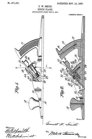
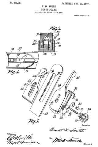
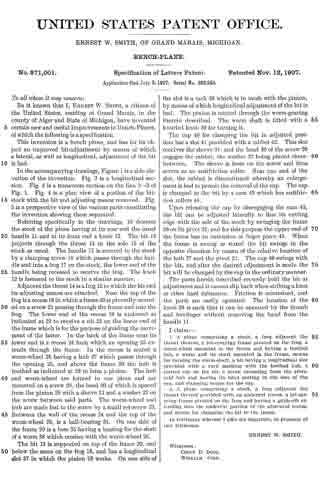
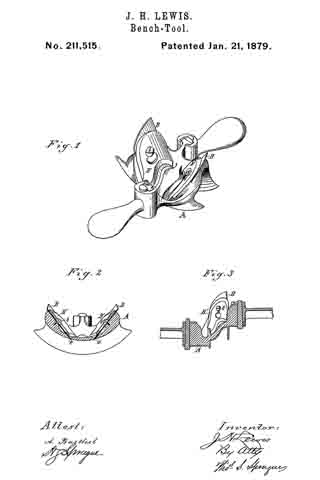
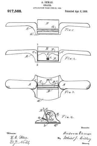
Figure 1 is a front elevation of the scraper. Fig. 2 is a back elevation of the same. Fig. 3 is a top plan of the same, and Fig. 4 is a transverse section of the same on the line x x of Fig. 2.

Similar letters refer to similar parts throughout the several views.

In the construction of this scraper I make use of a frame A, having handles projecting sidewise from the bit-holding portion of the frame, somewhat after the form of an ordinary spoke shave frame. The bottom, a’ of this frame is thin and broad and has a slot through its center, as at a” in Fig. 4, for the passage of the edge of the bit B, and an integral girth a arranged to bear equally across the entire length of the force of the bit a short distance above the bottom a’ so that with the bit in its proper position, as indicated in Fig. 4, the back of the lower edge of the bit will bear against the bottom a’ with the scraping edge b projecting just far enough below the bottom of the frame to engage the wood being scraped, to the desired depth. To secure the bit to place I provide an eccentric cam C, having a short lever c integral therewith, for actuating the cam to press its edge against the surface of the bit its entire length, thus forcing the upper edge of the bit forward so that its hotly will be forced against the girth a in such a manner that the back surface of the lower edge of the bit will bear heavily against the edge of the bottom a’, in the slot a”, the entire length of the bit, thus readily clamping the bit to place and holding it so securely the whole length that it will be impossible for any portion of the bit to tremble or “chatter” and render the surface being scraped, rough and uneven. This cam may be flattened at the point so that the pressure of the bit against it will hold it to place to retain the bit firmly in position.

I provide for averting the danger of drawing the bit upward with the cam C, by securing a thin metal plate D to the frame in such a manner that one lip thereof will extend upward between the point of the cam and the surface of the bit, so that the movement of the cam when clamping the bit to place will act upon the surface of the plate D, thus having no effect upon the bit to draw it upward. Without this, or some equivalent appliance, this tool would be inoperative, or practically so, for the reason that it would be almost impossible to hold the bit to the desired position while clamping it to place with the cam C. The cam C is pivotally supported in the frame A by means of a rod passing through it and forming short gudgeons projecting from each end, as at c’, into corresponding holes in the frame, as indicated in Figs. 2 and 3, and has a short lever c projecting down from its longitudinal center, with which to actuate it for securing or liberating the bit, as hereinbefore described and as shown in Figs. 2. 3, and 4.

It will be noticed that the bit B, in this tool, inclines to the front, instead of to the back as with planes &c., which position is bit the finished than the cutting designed for use necessary to give to the results of a scraper rather results of a plane, it being after the plane has reduced the surface to as near a finished surface as is possible with a plane, and before the application of sandpaper for a final finish.

I find that the most convenient, and in fact, the only really practical way to pivot the cam C into the frame is to drill a hole through the side of the frame and the length of the cam and pass a rod through of suflicient length to engage the frame at both ends of the cam, in which case the rod must be securely clamped into the cam to avert the danger of its sliding endwise and one end becoming disengaged from the frame. Another object to be carefully provided for is to so place the cam, and so finish its bearing edge, the bearing edge of the girth a and the bearing edge of the bottom plate a’ in the slot a” that the corresponding portions of the bit B will have perfect contact the entire length of the several bearing edges here mentioned. To release the bit B for removing it from the frame, it is only necessary to throw the handle c of the cam C up to the position indicated by the dotted lines in Fig. 4 when the plate D will be released and the bit may be readily removed or inserted.

What I claim as my invention, and desire to secure by Letters Patent, is:

In a furniture scraper, a supporting frame, a thin bottom thereto having a longitudinal slot through it, a girth connecting the sides of the trains above the bottom plate, in position so that a line from the bearing b on the bottom directly across the bearing face of the girth will incline sharply forwad, a bit extending up from the slot to and some distance above the girth, a protecting plate secured to the bottom of the frame and extending up along the surface of the bit, and a cam pivotally secured in the frame in position to bear against the protecting plate and force the bit solidly between the cam and the bearing b in the bottom of the frame on one side, and the girth on on the other side.

Signed at Grand Rapids Michigan June 19th, 1908.

ANDREW EKMAN.

In presence of —
T. M. NESBITT,
GEORGE L. KELNER.

No. 871,001 – Bench-Plane (Ernest W. Smith) (1907)

[paiddownloads id=”651″]871001


UNITED STATES PATENT OFFICE.

_________________

ERNEST W. SMITH, OF GRAND MARAIS, MICHIGAN.

BENCH-PLANE.

_________________

871,001. Specification of Letters Patent. Patented Nov. 12, 1907.
Application filed July 5, 1907. Serial No. 382,245.

_________________

To all whom it may concern:

Be it known that I, ERNEST W. SMITH, a citizen of the United States, residing at Grand Marais, in the county of Alger and State of Michigan, have invented certain new and useful Improvements in Bench-Planes, of which the following is a specification.

This invention is a bench plane, and has for its object an improved bit-adjustment by means of which a lateral, as well as longitudinal, adjustment of the bit is had.

In the accompanying drawings, Figure 1 is a side elevation of the invention. Fig. 2 is a longitudinal section. Fig. 3 is a transverse section on the line 3–3 of Fig. 1. Fig. 4 is a plan view of a portion of the bit-stock with the bit and adjusting means removed. Fig. 5 is a perspective view of the various parts constituting the invention showing them separated.

Referring specifically to the drawings, 10 denotes the stock of the plane having at its rear end the usual handle 11 and at its front end a knob 12. The bit 13 projects through the throat 14 in the sole 15 of the stock as usual. The handle 11 is secured to the stock by a clamping screw 16 which passes through the handle and into a frog 17 on the stock, the lower end of the handle being recessed to receive the frog. The knob 12 is fastened to the stock in a similar manner.

Adjacent the throat 14 is a frog 18 to which the bit and its adjusting means are attached. Near the top of the frog is a recess 19 in which a frame 20 is pivotally mounted on a screw 21 passing through the frame and into the frog. The lower end of the recess 19 is undercut as indicated at 22 to receive a rib 23 on the lower end of the frame which is for the purpose of guiding the movement of the latter. In the back of the frame near its lower end is a recess 24 from which an opening 25 extends through the frame. In the recess is seated a worm-wheel 26 having a hub 27 which passes through the opening 25, and above the frame 20 the hub is toothed as indicated at 28 to form a pinion. The hub and worm-wheel are formed in one piece and are mounted on a screw 29, the head 30 of which is spaced from the pinion 28 with a sleeve 31 and a washer 32 on the screw between said parts. The worm-wheel and hub are made fast to the screw by a small set-screw 33. Between the wall of the recess 24 and the top of the worm-wheel 26, is a ball-bearing 34. On one side of the frame 20 is a boss 35 having a bearing for the shaft of a worm 36 which meshes with the worm-wheel 26.

The bit 13 is supported on top of the frame 20, and below the same on the frog 18, and has a longitudinal slot 37 in which the pinion 28 works. On one side of the slot is a rack 38 which is in mesh with the pinion, by means of which longitudinal adjustment of the bit is had. The pinion is rotated through the worm-gearing therein described. The worm shaft is fitted with a knurled knob 39 for turning it.

The cap 40 for clamping the bit in adjusted position has a slot 41 provided with a rabbet 42. This slot receives the sleeve 31, and the head 30 of the screw 29 engages the rabbet, the washer 32 being placed therebetween. The sleeve is loose on the screw and thus serves as an antifriction roller. Near one end of the slot, the rabbet is discontinued whereby an enlargement is had to permit the removal of the cap. The cap is clamped to the bit by a cam 43 which has antifriction rollers 44.

Upon releasing the cap by disengaging the cam 43, the bit can be adjusted laterally to line its cutting edge with the sole of the stock by swinging the frame 20 on its pivot 21, and for this purpose the upper end of the frame has an extension or finger piece 45. When the frame is swung as stated the bit swings in the opposite direction by reason of the relative location of the hub 27 and the pivot 21. The cap 40 swings with the bit, and after the desired adjustment is made the bit will be clamped by the cap in the ordinary manner.

The parts herein described securely hold the bit at adjustment and it cannot slip back when striking a knot or other hard substance. Friction is minimized, and the parts are easily operated. The location of the knob 39 is such that it can be operated by the thumb and forefinger without removing the hand from the handle 11.

I claim:–

1. A plane comprising a stock, a frog adjacent the throat thercof, a bit-carrying frame pivoted on the frog, a worm-wheel mounted in the frame and having a toothed hub, a worm and its shaft mounted in the frame, means for turning the worm-shaft, a bit having a longitudinal slot provided with a rack meshing with the toothed hub, a slotted cap on the bit, a screw extending from the aforesaid hub and having its head seating in the slot ot the cap, and clamping means for the cap.

2. A plane comprising a stock, a frog adjacent the throat thereof provided with an undercut recess, a bit-carrying frame pivoted on the frog and having a guide-rib extending into the undercut portion of the aforesaid recess, and means for clamping the bit to the frame.

In testimony whereof I affix my signature, in presence of two witnesses.

ERNEST W. SMITH.

Witnesses:
COLIN D. DOIG,
WILLIAM VION.

No. 868,803 – Beading Or Molding Tool (Alphonse Pellrin) (1907)

[paiddownloads id=”648″]868803


UNITED STATES PATENT OFFICE.

_________________

ALPHONSE PELLRIN, OF DETROIT, MICHIGAN.

BEADING OR MOLDING TOOL.

_________________

868,803. Specification of Letters Patent. Patented Oct. 22, 1907.
Application filed January 28, 1905. Serial No. 243,162.

_________________

To all whom it may concern:

Be it known that I, ALPHONSE PELLRIN, a citizen of the United States of America, residing at Detroit, in the county of Wayne and State of Michigan, have invented certain new and useful Improvements in Beading or Molding Tools, of which the following is a specification, reference being had therein to the accompanying drawings.

This invention relates to improvements in beading or molding tools, and its object is to provide a simple, cheap and efficient device so constructed that the cutting bit or blade may be rotated or turned to advance one end of the lower or cutting edge ot the bit along the line of its travel to give the same a shearing cut, and also to provide simple means for adjustably holding the bit which may be readily attached or detached.

A further object of the invention is to provide the same with a detachable sole plate and with certain other new and useful features, all as hereinafter more fully described, reference being had to the accompanying drawings, in which

Figure 1, is a front edge elevation of a device embodying the invention and showing the same partly in longitudinal section; Fig. 2, is an inverted plan view ot the stock with all detachable parts removed; Fig. 3, is a side elevation of one of the knife or bit holders, detached; Fig. 4, is a perspective view of one of the sole plates, detached; Fig. 5, is an end view of the device with the handle broken away; and Fig. 6, is an enlarged perspective view of one end of the device showing the same in transverse section through the center of one ol the bit holders.

As shown in the drawing 1 is the stock of the tool consisting of a flat bar which is formed with a handle 2 at each end and with two circular openings 3, one near each end of the flat bar or stock, to receive the bit holders 4, each consisting of a casting formed with an upwardly extending inclined bed 5 for the knife or bit 6, and with a downwardly extending ring-shaped flange 7 to fit the circular opening 3 in the stock. The ring 7 is provided with an outwardly extending circular flange 8 to engage the upper surface of the stock and the holder is adjustably secured in the opening by providing an elongated slot 9 in said flange 8 to receive a screw 10 extending throughout and engaging a screw-threaded opening in the stock. Extending forward from the bed 5 at each side of the bit is the side flange 11, each of which is provided with a notch 12 extending downward from its upper end to receive laterally extending arms 13 on the clamping plate 14 which is provided with a screw-threaded opening near its upper end to receive a clamping thumb screw 15 adapted to extend through said opening and engage the bit, thus rocking said plate on its arms and causing the lower end thereof to press upon the bit and clamp the same firmly to its bed.

The lower end or cutting edge ot the bit 6 is shaped to give the article worked upon the desired form and a sole or wear plate 16 formed on its lower face to conform to the configuration of said cutting edge, is secured to the under surface of the stock over each opening 3 by providing said plate 16 with upwardly extending lugs 17 at one end, forming a dovetail opening between them to receive a dovetail rib 18 on the adjacent end of the stock, beneath the handle, and to further secure each sole plate in place, a screw 19 is provided. An opening 20 in said sole plate is provided for the end of the bit, through which it extends and which is of a size to permit the shavings to pass.

A longitudinal slot 21 is formed in the stock between the openings 3 and the lower face of the stock is cut away adjacent to said slot to term a longitudinal groove 22 to receive the stops 23 adapted to be adjusted along said groove and held therein by screws extending through the slot. These stops are provided to engage the edge of the board or other article being grooved or formed and cause the groove to be formed at the desired distance from the edge thereof.

For convenience the tool is provided with two bits or cutters but it is obvious that only one may be employed and by the particular construction of clamping plate but one screw is necessary and the plate and bit may be quickly removed by simply loosening the thumb screw.

By loosening the screws 10, the holders 4 may be turned within the openings 3 to set the blades or bits at an angle to the longitudinal axis of the stock or bar 1, so that one end of the cutting edge of each will cut in advance of the other end thereof and thus have a shearing action and so that the ends of said cutting edges may be moved nearer or farther from each other, thereby permitting line adjustment of the distance between the outer lines of the cut to be made.

Having thus fully described the invention what I claim is:

1. A routing tool comprising a stock adapted to be moved laterally across the work, a pair of bit holders each secured near one end of the stock, rotatable on an axis vertical to the plane of the stock, and each provided with a bit throat, a bit bed, a bit clamping plate and a bit having a cutting edge whose outer end projects beyond the body of the edge, so disposed that limited relative adjustment of the stock is obtained by the rotation of the bit holders, a guide slot between the bit holders in their axial plane, a gage plate for each bit holder adjustably secured in the slot, and a sole platefor each bit detachably interlocked with the stock outside of each bit holder, extending over and in register with the throat of the holder.

2. A routing tool comprising a narrow, substantially rectangular stock, adapted to be laterally moved across the work, handles on each end of the stock, integral therewith, a pair of bit holders, each consisting of a cylindrical base rotatably secured near one end of the stock vertically to the face of the stock, with its lower face flush with the stock face, means for clamping the holders in any desired angular relation to the stock, comprising a peripheral flange on the base, bearing on the upper side of the stock, a segmental slot in the flange, and a stud screw clamping the flange to the stock, passing through said slot, oblique means for securing a bit in each holder consisting of a bit bed extending obliquely up from the base, marginal, longitudinal flanges on the bed, longitudinally disposed grooves in the upper end portions of the flanges, a bit clamping plate provided with integral, alined lateral lugs between its ends, rocking and sliding in said grooves, and a thumb screw in the upper part of the clamping plate above the lugs, substantially perpendicular to the bed, means for centering the bit holders in relation to a neutral zone, consisting of a longitudinal slot in the stock between the bit holders in axial alinement therewith, whose margins in the stock bed are rabbeted to form a guide, gage plates for the bit holders, each provided with a longitudinal rib engaging the guide, adapted to center the bits in relation to a neutral surface between them, means for shielding bits in the holder comprising soles for each bit holder, each comprising a plate having an opening whose margins register substantially with the working edge of a bit, detachably held in alinement with a bit holder by a rib integrally fortned on the underside of the adjacent handle shank, adapted to dovetail with a lug integral with the plate, and a screw clamping the plate to the stock face over the bit holder.

3. A routing tool comprising a stock having a rectangular plane bed, handles integrally formed at each end thereof, a pair of bit holders in parallel spaced relation, each comprising a cylinder whose axis is perpendicular to the stock bed, each rotatably secured in an aperture in the bed near one end thereof, with their lower end faces flush with the bed, an annular flange on the upper end of each cylinder bearing on the upper side of the stock, a segmental slot in each flange, a screw passing through the slot, secured in the bed, a diametrically disposed throat opening in each cylinder, a lug extending obliquely from each cylinder, whose upper face is longitudinally grooved for a bit bed, a bit clamping plate, tiltably secured over each bed by integral, lateral lugs between the ends of the plate, sliding and rocking in parallel, longitudinal grooves in the side faces of the bed groove, a clamping thumb screw for each plate engaging a screw-threaded aperture in the upper end beyond the lugs, longitudinal, alined, undercut ribs on the under sides of the handle shanks, a shoe for each bit holder, provided with a lug adapted to detachably engage the adjacent undercut rib, and a countersunk screw engaging the stock, a longitudinal, rabbeted slot between the holders in their axial plane, an angle gage plate for each bit holder engaging said rabbeted slot, and a screw clamping each gage plate.

4. A routing tool comprising a stock, draw handles integrally formed at each end thereof, a bit holder rotatably secured at its lower end in the stock, axially perpendicular thereto, whose lower face is flush with the face of the stock, and is diametrically slotted to form a throat, a bit bed extending obliquely upward from the throat, parallel, longitudinal flanges on the sides of the bed integral with the holder, parallel slots in the upper parts of the flanges, a bit clamping plate provided with lateral alined lugs between its ends adapted to slide and rock in said grooves, a thumb-screw in the upper end of the plate transverse to the bed, a sole plate adapted to shield the projecting portion of the bit below the stock, a lug integral with the sole, detachably dovetailed to a rib integral with one of the handle-shanks beyond the end of the bed, a longitudinal guide slot in the bed between the bit holder and the other handle, and an adjustable gage for the bit longitudinally movable in said guide slot.

In testimony whereof I aflix my signature in presence of two witnesses.

ALPHONSE PELLRIN.

Witnesses:
OTTO F. BARTHEL,
THOMAS G. LONGSTAFF.

No. 827,473 – Plane (Lewis Dorus Smith) (1906)

[paiddownloads id=”634″]827473


UNITED STATES PATENT OFFICE.

_________________

LEWIS DORUS SMITH, OF PORT HURON, MICHIGAN, ASSIGNOR TO
STANLEY RULE AND LEVEL COMPANY, A CORPORATION OF CONNECTICUT.

PLANE.

_________________

827,473. Specification of Letters Patent. Patented July 31, 1906.
Application filed March 15, 1904. Serial No. 198,203.

_________________

To all whom it may concern:

Be it known that I, LEWIS DORUS SMITH, a citizen of the United States, residing at Port Huron, county of St. Clair, State of Michigan, have invented certain new and useful Improvements in Planes, of which the following is a full, clear, and exact description.

My invention relates to improvements in planes, and particularly to a plane which is adapted to carry any one of a large variety of cutters or plane-irons. A plane of the same general class is shown in the United States Letters Patent No. 532,84.

The object of my invention is to construct a plane which shall be efficient and readily interchangeable and adjustable for different classes of work. I have also sought to make the construction as simple as possible, so that the adjustments and interchanges may be effected easily, and the cost of manufacture may be reasonable. I have also sought to construct a plane which shall be useful in connection with classes of work hitherto impossible to planes of this type.

A plane embodying my invention is shown in the accompanying single sheet of drawings. Two parts of the plane are adjustable laterally with relation to one another and adapted to carry a plane-iron. Between the two adjustable portions is located a gage for limiting the cutting depth of the iron. This gage is adjustable vertically and laterally and is readily removable. When desired , an auxiliary guide may be employed.

Figure 1 is a side elevation of a plane embodying the improvements of my invention, a portion of an auxiliary guide being shown dotted. Fig. 2 is a front elevation of a plane embodying the improvements of my invention shown as in operation. Fig. 3 is a detail perspective view of the center gage and attachments. Fig. 4 is a bottom view of the complete plane. Fig. 5 is a vertical sectional view on the plane of the gage-support.

1 is the main stock portion having a handle 2 and a guide-blade 3.

4 is a plane-iron, having a suitable cutting edge — as, for instance, a “hollow.”

5 is a screw of suitable construction for clamping the plane-iron to the main stock 1.

6 is an adjusting screw for varying the cutting depth.

7 is a gage carried at the outer side of the main stock and adjustable in a suitable manner by means of the screw 8.

9 is a guide-rod which extends laterally from the main stock 1 and may be secured thereto by means of the screw 10. 11 is a similar guide-rod at the rear, which may be attached to the main stock by means of the screw 12.

13 is what may be conveniently termed a “sliding section,” having the guide-blades 14 and 15 corresponding to the guide-blades 3 and 30 of the main stock. This section 13 is adjustable laterally on the guide-rods 9 and 11 to and from the main stock 1. 16 and 17 are thumb-screws for holding it in the desired position. In the instance herein shown the distance from the outer surface of the guide-blade 3 to the outer surface of the guide-blade 14 is approximately equal to the width of the cutter or plane-iron 4.

18 indicates a section of a molding, a portion of which has just been formed by the cutter 4. It will be obvious to one acquainted with this art that cutters of many different forms may be employed with a tool of this character to shape a molding, as desired.

19 is a gage for steadying the plane and limiting the cutting depth of the plane-iron 4. 20 is a post which is vertically adjustable in a recess in the outer surface of the sliding section 13. 21 is a thumb-screw for securing it in place. 22 is a horizontal member for connecting the adjustable post 20 and the gage 19. In this instance the horizontal bar is carried by the post 20. 23 is a thumb-screw which clamps the gage to the horizontal cross-bar 22. The gage preferably has an enlarged portion 24 at the top, which is open at the rear, so that the gage may be removed by simply loosening the screw 23 and slipping the gage forward. The gage in this way may be removed without being obstructed by the guide-rod 9. By this construction the center gage 19 may be adjusted vertically and also laterally, so as to provide for different widths and conformations of cutters.

25 is a longitudinal guide or fence which may be carried by the longitudinal guide-rods 9 and 11 and adjustable laterally thereon. 26 is a handle for convenience in operation. Such a guide or fence is not necessary in all kinds of work; but in forming a molding, as herein illustrated, it is advantageous.

What I claim is —

1. In a plane, the combination of a handle member, a sliding section member adjustable relatively thereto, a laterally-projecting lug carried by one of said members and having a vertical passage-way, a post passing through and vertically adjustable in said passage-way, a laterally-extending thumb-screw passing through said lug for coacting with said post, and a center gage located between said members and means for supporting said gage from said vertical post.

2. A plane-gage attachment of the character described comprising the combination of two substantially parallel rods, a shoe member carried by one of said rods, a connecting member having one endf fixedly secured to one rod and an adjustable clamping means carried by the other rod for engagement with said member and having an open horizontal slot, substantially as described for the purpose specified.

3. A plane-gage attachment of the character described, and for the purpose specified, comprising the combination of two substantially parallel rods spaced apart from each other, a shoe member carried by one of said rods, a laterally-projecting connecting member having one end fixedly secured to one of said rods, the other rod being laterally adjustable upon the connecting member of the first rod, and means for clamping the second rod upon said connecting member.

Signed at Port Huron, Michigan, this 5th day of March, 1904.

LEWIS DORUS SMITH.

Witnesses:
S. V. JONES,
LEWIS ATKINS.

No. 715,352 – Plane (Lewis M. Curry) (1902)

[paiddownloads id=”575″]715352


UNITED STATES PATENT OFFICE.

_________________

LEWIS M. CURRY, OF BRIGHTON , MICHIGAN.

PLANE.

_________________

SPECIFICATION forming part of Letters Patent No. 715,352, dated December 9, 1902.
Application filed March 29, 1902. Serial No. 100,512. (No model.)

_________________

To all whom it may concern:

Be it known that I, LEWIS M. CURRY, a citizen of the United States of America, residing at Brighton, in the county of Livingston and State of Michigan, have invented certain new and useful Improvements in Planes, of which the following is a specification, reference being had therein to the accompanying drawings.

My invention relates to improvements in carpenters’ planes; and its object is to provide a cheap and simple construction which is strong and durable, having few parts, easily assembled, and not liable to get out of order, and to provide ready means for accurately adjusting the plane-bit longitudinally within the throat and to so construct the parts as to allow for a slight lateral adjustment of the bit, it also being the object of this invention to provide means for clamping the bit and its shavings-breaker to the support therefor, so that they are firmly held without the necessity of a clamping-plate or other obstruction on the upper side of the breaker, and the bit will be frictionally held against accidental lateral movement thereby, but may be so adjusted by the operator.

To this end the invention consists in providing a longitudinally-movable carrier for the bit, which carrier is supported at an inclination substantially the same as that of the bed and free to move laterally on its support, and in providing suitable means for securing the bit to the carrier at one end, which means also serves to hold the lower end of the bit in strong frictional contact with the bed to prevent such lateral movement of the bit except when adjusted by the operator; and the invention further consists in providing suitable mechanism for moving the carrier and attached bit longitudinally to regulate the cut, and also in the particular construction, arrangement, and combination of parts, all as more fully hereinafter described, reference being had to the accompanying drawings, in which —

Figure l is a perspective view of a device embodying my invention; Fig. 2, a longitudinal vertical section through the bit and adjacent parts and a portion of the stock on the line 2 2 of Fig. 3. Fig. 3 is a section on the 2, showing a plan view of the line 3 3 of Fig. 2; Fig. 4, a section on the line 4 4 of Fig. 2, showing the carrier in plan; Fig. 5, the same, showing the carrier in section and illustrating the manner in which the bit is adjusted laterally; and Fig. 6 is a longitudinal vertical section similar to Fig. 2, showing a modified adjustment for the carrier and showing the bit unclamped to illustrate the manner in which it is held against the bed.

A is the stock of the plane, formed, in the usual manner, of hard wood, with a throat A’, having the mouth A2, and one side extended at an inclination of about forty-five degrees to form the bed A3, upon which the bit-iron or knife rests.

B is a casting secured to the top of the stock and provided with upwardly-extended supporting flanges or sides B’, which form bearings for the transverse pin C and eccentric-rod D, which support the bit-carrier E. Said carrier E consists of a rectangular casting having its middle portion cut away to lighten the same and provided with a lug E’, projecting from its lower end, which lug has an elongated opening E2 or slot through which the pin C extends, and through a transverse opening E3, near its upper end, extends the eccentric-rod D, which rod is provided with bearing ends D’ and D2 to engage the bearings in said sides B’. The rod D is set eccentrically to its bearing ends, so that when the same is turned by the knurled head D3, which is secured on the outer end of the reduced portion D4, the carrier will be moved a distance equal to the throw of said eccentric, and to secure the eccentric in place and connect the sides B’ a yoke F is provided, which embraces the sides B’ and is secured at its lower ends by the pin C, which extends therethrough and is riveted at its outer ends and near the top of the sides by the screws F’, said yoke extending over and closing the outer end of the opening forming the bearing for the end D’ of the eccentric and has an opening to at the reduced portion D4, thus securing the eccentric in place and forming a brace for the sides B’.

The knife or bit-iron G and its cap-iron or shavings-breaker H are secured together in the usual manner by a set-screw H’ engaging a slot G’ in the bit. The breaker is nearly as long as the bit and is provided with openings H2, having lateral extensions H3, located opposite the slot G’, to receive the heads of the screws I and J, which screws engage screw-threaded openings I’ and J’ in the carrier E, the head of the screw I forming an abutment to engage the upper side of the breaker.

The carrier E is supported at substantially the same inclination as the inclination of the bed A3, and the screw I is adjusted to bring its head at such a height relative to the bed that when said head is passed through the openings H2 and the breaker moved to engage the extension H3 with the shank of the screw the lower end of the bit will engage the bed adjacent to the mouth.

A binding-screw K engages a screw-threaded opening K’ in the carrier E, and on the inner end of said screw is a head K2, a recess K3 being provided in said carrier for said head, which head is forced upward by the turning of the screw into engagement with the under side of the bit and forces the lower end of the bit against the bed, the screw J being properly adjusted relative to the screw I to form a stop to prevent the bit from being bent too far by the action of the screw. The turning of the binding-screw K thus not only secures the bit to the carrier, but forces the same into frictional contact with the bed by the spring of the said bit, and by adjusting the screws I and J the frictional contact may be increased or diminished and the angle of the bit changed, so that it will lie flat upon the bed or will contact the same only at its lower end.

The carrier is made somewhat narrower than the space between the sides B’, and the eccentric is made to have a little play in its bearings, so that said carrier may be shifted laterally. When the bit is in place, the frictional contact thereof with the bed will hold the lower end of the bit so that when the upper end of the carrier is shifted the bit will be tilted to bring its cutting edge even with the sole of the stock when the bit is not ground exactly true, as shown in Fig. 5, and the spring action of the bit and its breaker causes a friction on the eccentric D, so that it will not be accidentally turned.

If desired, an adjusting-screw L, passing through an opening in the yoke F and engaging screw-threaded openings in the carrier, may be provided to move the carrier instead of the eccentric D; but I prefer said eccentric, as it is more accurate, is simple, cheap, and more durable.

Having thus fully described my invention, what I claim is —

1. In a plane, the combination with the stock; of side flanges on said stock, a bit, a movable carrier to which the bit is secured, and means supported by said flanges for supporting and moving the carrier to adjust the bit.

2. In a plane, the combination with the stock; of side flanges on said stock, a laterally-movable bit-carrier, a bit secured to said carrier, and means on the flanges for supporting the carrier and upon which it may be moved laterally of the stock to tilt the bit.

3. In a plane, the combination with the stock; of side flanges on said stock, a bit-carrier supported by said flanges and adapted to be moved laterally between the same, a bit on said carrier, and means for securing said bit to the carrier and for causing a frictional resistance to such lateral movement of the carrier.

4. In a plane, the combination with the stock; of a bit adapted to be moved longitudinally, side flanges on said stock and an eccentric supported by said flanges and adapted to move said bit.

5. In a plane, the combination with the stock thereof having a bed; of a carrier supported upon said stock and provided with screw-threaded openings a bit having an opening and engaging said bed at one end, a screw engaging one of the openings in the carrier and projecting through said opening in the bit to engage its head with the upper side of said bit, and a binding-screw engaging the other opening in the carrier and contacting the under side of said bit.

6. In a plane, the combination with the stock and a bit thereof; of supporting-flanges on said stock, a carrier to which the bit is secured, supported by said flanges to move longitudinally and provided with a transverse opening, and an eccentric within said opening.

7. In a plane, the combination with the stock thereof; of supporting-flanges on said stock, a carrier having a slot and a transverse opening, a pin supported by the flanges and engaging said slot, a rod in said opening having eccentric ends engaging bearings in said flanges, a bit, and means for securing said bit to said carrier.

8. In a plane, in combination a stock having a bed, supporting-flanges on said stock, a carrier having a slot at its lower end and a transverse opening near its upper end and screw-threaded openings, a pin secured at its ends to the supporting-flanges and extended through said slot, a rod in the transverse opening and having eccentric ends engaging bearings in the flanges, and provided with a head, a bit having openings, screws having heads projecting through said openings and engaging the upper side of the bit and adjustable in the screw-threaded openings in the carrier, a binding-screw extending through said carrier and a head on said binding-screw engaging said bit.

9. In a plane, the combination of a stock a casing secured to the upper side of said stock, the supporting-flanges on said casings having openings, a longitudinaily-movable carrier having a slot and a transverse opening, a pin extending through the opening in the flanges and the slot in the carrier, a rod engaging the transverse opening in the carrier and provided with eccentric ends engaging bearings in said flanges and having a reduced portion provided with a knurled head, a yoke embracing the flanges and provided with an opening to receive the reduced portion of the eccentric, and a bit secured to said carrier.

In testimony whereof I affix my signature in presence of two witnesses.

LEWIS M. CURRY.

Witnesses:
LEWIS E. FLANDERS,
OTTO F. BARTHEL.

No. 556,835 – Carpenter’s Plane (George S. Smith) (1896)

[paiddownloads id=”527″]556835


UNITED STATES PATENT OFFICE.

_________________

GEORGE S. SMITH, OF GRAND RAPIDS, MICHIGAN.

CARPENTER’S PLANE.

_________________

SPECIFICATION forming part of Letters Patent No. 556,835, dated March 24, 1896.
Application filed April 20, 1894. Serial No. 508,365. (No model.)

_________________

To all whom it may concern:

Be it known that I, GEORGE S. SMITH, a citizen of the United States, residing at Grand Rapids, in the county of Kent and State of Michigan, have invented certain new and useful Improvements in Carpenters’ Planes; and I do hereby declare the following to be a full, clear, and exact description of the invention, such as will enable others skilled in the art to which it appertains to make and use the same.

My invention relates to an improved carpenter’s plane; and its object is to provide the same with certain new and useful features hereinafter more fully described and particularly pointed out in the claims, reference being had to the accompanying drawings, in which —

Figure 1 is a longitudinal vertical section, on the line 1 1 of Fig. 2, of a device embodying my invention 5 Fig. 2, a plan view of the same with the blade and wedge removed; Fig. 3, a vertical section on the line 3 3 of Fig. 1; Fig. 4, an inclined transverse section on the line 4 4 of Fig. 1, and Fig. 5 details showing openings to receive the adjusting-screw H.
Like letters refer to like parts in all of the figures.

A is the main frame of the plane, B the blade-supporting block, C the blade, D the wedge, E the adjusting-lever, and F the adjusting-screw, all being ot the usual construction.

In a suitable opening near the upper end of the blade-block B and laterally movable therein is a bar G, having a widened outer end, which is formed with lugs G’ to engage the sides of the blade and shift it laterally to square the edge of the same with the under surface of the plane. Said bar G is provided at its lower side with a screw-threaded concave surface engaging the side of a screw H. Said screw is provided with a milled head I and journaled in openings J’ J” in lugs J on the back of the block B. Said openings are elongated in the direction of the bar G, and one of the bearings of the screw H is reduced, and the corresponding opening J” is reduced at the lower end to engage this reduced bearing, whereby the screw is prevented from moving longitudinally.

The bar G is held in place in the block B by a screw K, the head of which screw overlaps said bar at one side for this purpose. By removing this screw K and bar G the screw H may be moved into the upper ends of the openings J’ J” and thence removed longitudinally, and when in place said screw is held by the engaging screw-threaded side of the bar G.

Within a suitable recess in the bottom of the plane and with its rear angle close to the cutting-edge of the blade C is a throat-slide L, having upwardly-projecting bosses L’, extending through elongated openings R. Screws P are inserted in said lugs, whereby the slide L is held in the recess and permitted to move longitudinally therein. A spring N is attached to a suitable yoke-frame M at its upper end and engages the slide L at its lower end to press said slide toward the blade C. A screw O engages said spring and a transverse rib Q, and serves to adjust the spring to determine the approach of the slide L to the blade C and thus adjust the opening or throat in front of said blade. Said block L, being movable and pressed toward the blade C by the spring, will yield to the shaving as it passes through the throat. It can therefore be adjusted very close to the blade and thus cause the tool to do very smooth work.

I am aware that a throat-block of somewhat similar construction to mine and capable of being adjusted to and from the blade has heretofore been patented, but said throat-block was not provided with a spring and was incapable of automatically yielding to the shavings, for which reason it did not prevent clogging of the throat.

I am also aware that an adjustable spring has been proposed to take the place of the sliding throat-block, which spring will of course yield to the shaving passing up through the month of the plane, but it will yield for a time only during the operation of the plane, as the space between its forward surface and the forward wall of the throat soon receives a sufficient quantity of shavings to force and hold the spring into contact with the cutter, thus not only preventing the spring from yielding, but entirely closing the exit for the shavings. By combining the sliding throat-block with a spring, which causes it automatically to yield to the quantity of shavings passing upward into the throat of the plane, said throat will not become choked and an open exit for the shavings is kept at all times, as will be readily seen.

What I claim is —

1. In a plane, the combination with the blade and its supporting-block, said block having elongated openings one of which has a reduced lower end, of a bar, laterally movable in said block, and engaged with said blade, an adjusting-screw for the bar and blade, said screw being seated in said openings in the block and having a reduced end corresponding with the reduction in the end of one of said openings, and a screw in said block, having its head overlapping one side of said bar and securing the same in place.

2. In a plane, the combination with the blade and its supporting-block, said block having an opening near its upper end and also having lugs formed with elongated openings, one of which latter has a reduced lower end, of a bar laterally movable in said block, said bar having a widened end formed with lugs engaging the sides of the blade, an adjusting-screw for the bar and blade, said screw being seated in the openings in the lugs of the block and having a reduced end corresponding with the reduction in the end of one of said openings, and a screw in said block having its head overlapping one side of said bar and securing the same in place.

3. In a plane, the body, having a recess in its under side adjacent to its throat, and also having an elongated opening, an upwardly-projecting rib and a yoke-frame, in combination with a movable throat-block in said recess, having an end extending upward into the throat of the plane and a boss extending through said elongated opening, a screw engaging said boss, a spring secured at its upper end to said yoke-frame and having its lower end engaged with the upturned end of said throat-block, and an adjusting-screw engaging said rib and spring, substantially as described.

4. In a plane, the body having a recess in its under side adjacent to its throat, in combination with a sliding throat-block within said recess, said block having an upturned part, and a spring engaging said upturned part of the throat-block and causing the latter automatically to adjust itself to the quantity of the shavings passing upward into the throat of the plane, substantially as described.

In testimony whereof I affiix my signature in presence of two witnesses.

GEORGE S. SMITH.

Witnesses:
LUTHER V. MOULTON,
LOIS MOULTON.

No. 323,595 – Plane-Guide (William Wallace Preston) (1885)

[paiddownloads id=”397″]323595


UNITED STATES PATENT OFFICE.

_________________

WILLIAM WALLACE PRESTON , OF COLDWATER, ASSIGNOR TO HIMSELF
AND EDWARD FLOYD PRESTON, OF BISMARCK, MICHIGAN.

PLANE-GUIDE.

_________________

SPECIFICATION forming part of Letters Patent No. 323,595, dated August 4, 1885.
Application filed January 3, 1885. (No model.)

_________________

To all whom it may concern:

Be it known that I, WILLIAM WALLACE PRESTON, of Coldwater, in the county of Branch, and State of Michigan, have invented a new and Improved Plane-Guide, of which the following is a full, clear, and exact description.

The object of my invention is to provide a simple, inexpensive guide or device of improved construction, for attachment to planes, to enable the edges of lumber to be squared or to be beveled at any desired angle either way by the planes, with accuracy and without the aid of a try-square or bevel, and with economy of time and labor.

The invention consists in particular constructions and combinations of parts of the plane-guide and its attachments to the plane, all as hereinafter fully described and claimed.

Reference is to be had to the accompanying drawings, forming part of this specification, in which similar letters of reference indicate corresponding parts in all the figures.

Figure 1 is a side elevation showing my improved plane-guide attached to a plane, as in use in squaring the edge of a board. Fig. 2 is a rear end sectional view of the same. Fig. 3 shows in end view the plane and its guide adjusted to bevel the edge of a board downward toward its finished face. Fig. 4 is an end view with the plane and its guide adjusted to utilize the outer part of the sharp edge of the plane-iron; and Fig. 5 is an end view illustrating the adjustment of the plane and its guide for beveling the edges of boards downward and backward from their finished faces.

The plane-guide in its preferred form consists, mainly, of three meta! parts: the fence A, or guide proper, the plate B, which is to be fixed to the side of the plane-stock, and the part C, which connects the parts A B by the aid of thumb-screws in the various adjustments of the plane-guide, as hereinafter more fully explained.

The fence A consists of a plate, A’, made either solid throughout or cut away at various places to decrease its weight, and having a strong flange, D, projecting at a right angle and in vertical plane from its back or outer face, and preferably from about the center of the plate A’ (See Fig. I.) I prefer to make the plate B with flanges b b at opposite edges, and to form a boss, b’, at the center of its face, to give sufficient body of metal to firrnly hold a thumb-screw, E, which is threaded into the boss. I attach the plate B by screws f, or otherwise, and it may be permanently, to the side of the stock F of the plane, and preferably near where the plane-iron or cutter G passes through the working-face H of the plane, and so that the flanges b b range up and down the side of the plane. The connecting-piece C is made with an upper portion, I, fitted to slide on the plate B between its flanges b b, and having a slot, i, through which the screw E passes, the flange or shoulder e of the screw being wider than the slot, so it may bind the part I to the plate B at any desired adjustment. The lower part, J, of the connection C is in the form of a flange which projects to one side or face of the upper part I, and in a plane at a right angle with said part, I, and so part J may lie face to face with the flange D of the fence A and be fastened to it by the thumb-screws K L, the screw K serving, when loosened, as a pivot on which to swing the parts A C to their various angles of adjustment, and the screw L, which passes through a curved slot, M, of plate D, serving, with the tightened screw K, to bind the parts C A firrnly together when set. The screws K L enter threaded holes in the lower part or flange, J, of the connection C. I cut away the upper edge of the fence-plate A’, as at a, and for a depth a little greater than the maxirnum projection of the plane-iron G from the plane-face H, so that said face always may lie closely on the upper edge of the fence-plate, and the pivot-screw K is located in such relation to the parts A C of the plane-guide that the corner of the plane-iron nest the guide always will project inward beyond the contacting faces of the fence A and the board O to be jointed, as seen best in Figs. 2 and 3. The adjustment and operation of my improvement are as follows: In jointing the edges of boards O squarely with their finished face o, against which the fence-plate A is held and moves as the plane is operated, or in jointing at a slight back bevel or undercut suitable for the edges of base-boards, door-jambs, and the like, or in jointing at any bevel from forty-five degrees (more or less) downward toward the face o of the work, the part C will be adjusted with its lower part or flange, J, outward, so that the screw K may be entered into the threaded hole 1 of said flange, as shown in Figs. 2 and 3. In square-jointing the boards the fence-plate A’ will be set square with the edge of the plane-iron when the screw E binds the parts C B together, so that the plane-face H rests on the top of the fence-plate A’, as seen in Fig. 2, and the screw L then will be passed through the slot M into the threaded hole 2 of the flange J, and the screws K L then are tightened and the plane is ready for work. To bevel the edge of the board O under slightly toward the back, the screws E K L will be loosened and the plane will be swung over to the right hand on pivot K, or the fence A swung under the plane to the desired angle, and the screws K L will be tightened. The loose screw E, which had allowed the plate B to lift or draw upward on the part I of connection C, will then be tightened, when the plane-face H rests on the upper edge of the fence-plate A’, and the plane is ready for work. To bevel the edge of the board O downward toward its face o, the screws K L will be loosened, and the connection C and the plane will be swung downward to the left hand, the screw L then moving through the slot M, and when the plane-face H stands at the desired angle with the working-face of the fence-plate A’, the screws K L will be tightened; but this adjustment throws the plane-face H away from the fence-plate A’, and to bring them in contact the screw E will be loosened, so that the part I of connection C may be slid upward, or the plane and its plate B be slid downward until the plane-face H rests against the top of the fence-plate A’, the flange D being out away at d to allow this adjustment, and the screw E then will be tightened and the plane is ready for work, as seen in Fig. 3, which shows the tool set to joint the edge of the board at an angle of forty-five degrees; but the adjustments to work at angles greater or less than that shown may readily be made as the work to be done shall require. In squaring or slightly back-beveling the edges of the boards, with the pivot-pin K entered in the screw-hole 1 of the flange J, as in Fig. 2, the left-hand side or edge portion, g, of the plane-iron G will be used, and to provide for utilizing the right-hand sharp edge portion, g’, of the iron when the portion g becomes dulled by use so as to avoid frequent whetting or sharpening of the iron, and also to provide for jointing the boards at a considerable back bevel, the connection C will be reversed in position, and the pivot-screw K will be entered into the screw-hole 2, and the screw L will be turned into the screw-hole 3 of the flange portion J of connection C, as in Figs. 4 and 5. In squaring the edges with the part g’ of the plane-iron, as in Fig. 4, the screws K L will be tightened when the screw L is at or near the lower part of the slot M of flange D; but in setting the plane over to joint at a back downward bevel at any desired inclination from a square edge to an angle of forty-five degrees or more, the screw L will move upward in the slot M, more or less, as required, and the screw E will be tightened when the face H of the plane rests on the top edge of the fence-piece A’. In Fig. 5 the plane is set to back-bevel the lumber at an angle of forty-five degrees.

It will be seen that in every described adjustment of the plane and guide the plane-face is in contact with the guide fence-piece A’, and that it only is necessary in using the plane to hold the fence-piece flat against the finished face of the lumber to secure accurately squared or beveled edges of the lumber, and without the inconveniences and delays incident to the use of try-squares or bevels, thus enabling the workman to do more accurate work and a largely-increased amount of it in a given time.

If desired, the plate B may be let in flush with the side face of the plane, and when a plane is to be used for squaring or for beveling at one angle only, the plate B may be dispensed with and the upper plate or part, I, of the connection C will then be fastened directly to the side of the plane-stock; but the use of the plate B and screw E is preferred for securing the various adjustments allowed by them with a single plane, as above described.

Any suitable fastenings may be substituted for the thumb-screws K L which will serve their purpose — such as nutted bolts; but the thumb screws are preferred because of their convenience in effecting the adjustments of the plane-guide.

Having thus described my invention, what I claim as new, and desire to secure by Letters Patent, is —

1. A plane-guide comprising a fence, A, formed of a plate, A’, having a flange, D, provided with a curved slot, M, and a set-screw, K, passing through the said flange in the same horizontal plane as the upper end of the slot, a reversible connecting-piece, C, formed with the lower flange, J, and upper plate, I, in planes at right angles to each other, the said flange J having holes 1 and 2 in horizontal alignment, and the set-screw L, whereby the set-screw K may serve as a pivotal point and the set-screw L the adjusting point to allow of adjustments, substantially as set forth.

2. A plane-guide comprising a fence, A, formed of a plate, A’, having a flange, D, provided with a curved slot, M, and a set-screw, K, passing through the said flange in the same horizontal plane as the upper end of the slot, a reversible connecting-piece, C, formed with the lower flange, J, and upper plate, I, in planes at right angles to each other, the said flange J having holes 1 and 2 near its upper edge in the same horizontal plane, and a hole, 3, near its lower edge, and the set-screw L, adapted to engage either one of the said holes, for adjustment when one of the other holes is engaged by the set-screw K as a pivotal point.

3. In a plane-guide, the combination, with the fence A and its flange D at right angles therewith, of the reversible connecting-plate C, having a flange, J , in the plane of flange D, and adljustably pivoted to said flange D, and a binding-screw for locking said parts in their adjusted positions, substantially as set forth.

WILLIAM WALLACE PRESTON.

Witnesses:
WM. H. BENEDICT,
GEO. T. CULVER.

No. 316,296 – Plane (Louis C. Rodier) (1885)

[paiddownloads id=”391″]316296


UNITED STATES PATENT OFFICE.

_________________

LOUIS C. RODIER, OF DETROIT, MICHIGAN.

PLANE.

_________________

SPECIFICATION forming part of Letters Patent No. 316,296, dated April 21, 1885.
Application filed November 8, 1884. (Model.)

_________________

To all whom it may concern:

Be it known that I, LOUIS C. RODIER, of Detroit, county of Wayne, State of Michigan, have invented a new and useful Improvement in Planes; and I do hereby declare the following to be a full, clear, and exact description of the same, such as will enable others skilled in the art to which it pertains to make and use it, reference being had to the accompanying drawings, which form a part of this specification.

My invention relates to bench-planes, and more particularly to metallic bench-planes, and has for its object, first, the combination, with a stock, of an improved knife holder or carriage provided with devices for operating the same and adjusting the knife to secure the desired depth of cut; second, the combination, with a stock, of a novel attachment for holding a toothing iron or scraper; third, to combine in a bench-plane the said knife-holder and said attachment for toothing irons and scrapers, said attachment being removable, so that the knife or bit may be removed and the toothing or scraper attachment be engaged with the stock,or said attachment be removed and the knife inserted, the plane being thus readily convertible for various uses; and, fourth, it consists in the general construction and arrangement of the novel devices, hereinafter described, and more particularly pointed out in the claims.

I carry out my invention as follows:

In the drawings, Figure 1 is a longitudinal section of a jack-plane, showing the knife-holder in position with the knife or bit in place. Fig. 2 is a similar section showing the toothing or scraper attachment in position. Fig. 3 is a modihcation adapting features of the device more particularly for a smoothing-plane or block-plane. Fig. 4. is a separate view of the toothing iron and scraper attachment. Fig. 5 is a cross-section along the line at x y, Fig. 6. Fig. 6 is a view showing the knife-carriage and its operating devices. Fig. 7 is a side elevation.

A represents the stock provided with a throat, a.

B is the knife-rest, which may be constructed of any suitable form or pattern, and adapted to hold the knife on a proper incline. It may be provided with ears b extending upward at the side of the knife, or these ears may be dispensed with, as shown in Fig. 3. This knife-rest is provided with a rearwardly-extending arm, b’, provided with a screw-orifice, b2, (shown in Fig. 1,) or otherwise adapted to receive the head of a screw, and to receive its force, as shown in Fig. 3. I also prefer to construct the knife-rest, when applied to jack-planes, with an extended knife-brace, b8. This knife-rest may be secured within the walls of the stock and suitably adjacent to the throat in any suitable manner, as sh own in Fig. 5. The knife-rest is screw-tapped to receive the screws b3 and b4 These screws are preferably constructed with rounded ends to engage in corresponding sockets, a’ and a2, in the base of the stock, the construction being such that the knife-rest may have a movable or slightly-vibratory movement, so that either side of said knife-rest may be elevated or depressed to more effectually adjust the knife to cut evenly across its entire edge.

C is a spring engaged with the knife-rest at one end, as shown at c, and under the arm b’
and upon a raised bed, A’, upon the base of the stock.

D is a bridging constructed preferably integral with the stock, under which the spring is extended, said bridging also preferably provided with a screw, d, adapted to bear upon the spring to give it greater tension upon the knife-rest. I do not limit myself to any special construction of this bridging.

The bed A’ is screw-tapped, as shown at a3, to receive a screw, B’.

B2 is a thumb-nut adapted to operate upon said screw, and to bear upon the rear of the arm b’ to tilt the knife-rest to any desired angle.

E is a knife-clamp provided with hooked arms e, adapted to engage over the ears b of the knife-rest, said ears being suitably cut away at their rear edge to receive said hooked arms, so that the one will be flush with the other, as shown in Fig. 7. The side walls of the stock are preferably cut away slightly to receive said ears and arms also, as shown also in Fig. 7.

E’ is a thumb-screw tapped into said clamp and adapted to tighten and hold the knife upon the knife-rest beneath. F is the knife. The clamp may have, however, any suitable engagement with the knife-rest.

When the thumb-nut B2 is forced down upon the arms b’ of the knife-rest, the effect will be to tilt the knife-rest and so adjust the knife relatively to the throat, said rest being adapted to have a slight longitudinal vibratory motion upon the ends of the screws b3 and b4, as well as a vibratory motion across the stock, while the pressure of the thumb-screw E clamps the lower part of the knife-clamp upon the knife near its cutting-edge, so that the knife is held firmly between said clamp and the knife-rest. The knife is thus readily held in position. The knife may be put in place by loosening the clamp, which is then raised to disengage its hooked arms from the ears of the knife-rest. When the knife is in place, the clamp is forced down so that its hooked arms shall be engaged over the ears of the knife-rest, and the thumb-screw may be tightened thereon when the cutting-edge of the knife has been properly adjusted.

As shown in Fig. 3, instead of providing the knife-rest with the screws b3 and b4, having rounded ends, forming the bearings of said rest, I may construct said rest with integral bearings or lugs b5, answering the same purpose as the screws in Fig. 5, the only difference being that the knife-rest cannot readily be adjusted across the stock as can be done, as already described, where the screws b3 and b4 are employed. So, also, instead of engaging the spring in the knife-rest, as shown in Figs. 1 and 2, the tension may be secured in essentially the same way by constructing the arm b with a cross-bar, as shown at b6, in which case the end of the spring may be engaged under the bridging, being passed over said cross-bar, as shown in Fig. 3, the tension being secured by means of the screw B’. By operating said screw the knife-rest may be tilted, as before, to secure the desired adjustment of the knife relative to the throat to make it cut more or less, as may desired.

To insure the proper location of the knife upon the rest and relatively to the throat, I also prefer to construct the knife with an orifice, f adapted to engage over a lug, G, which may be adjustably located beneath it either upon the spring, as shown in Fig. 3, or upon an arm, b7, integral with the knife-rest. This device when the lug is once adjusted properly will permit the ready engagement of the knife relatively to the throat, and when the knife becomes worn the lug can be adjusted to compensate for the wear.

H represents my improved toothing iron or scraper attachment, substantially as shown in Fig. 2, consisting of a suitable front clamp, H’, and rear clamp, H2, the front clamp being preferably provided with engaging-arms h, adapted to engage upon the rear clamp, said clamps provided with thumb-screws h and h2 to bind the toothing iron or scraper H3 between said clamps, as shown in Fig. 2. By means of the said screws the toothing-iron may be readily engaged in said clamps or removed thereupon for the insertion of the scraper, as desired, said clamps forming a holder or harness for the cutting-tool.

The rear clamp is provided with a wing, h3, constructed and arranged to be seated upon the knife-rest B. The knife-clamp E is then clamped upon the wing, the knife F being removed, which holds the said attachment firmly in place. It is evident that this attachment may be readily removed and the knife inserted, and vice versa.

Instead of engaging the wing h3 upon the knife-rest by means of the knife-clamp already described, the wing itself may be provided with engaging-shoulders h4, similar to the hooked arms e of said clamp, and serving a similar purpose.

I design to provide the stock of the plane with a scale-bar or measure, as shown in Fig. 7. The spring serves to take up any slack which may result in the adjustment of the knife-rest by means of the screw B’.

In the jack-plane, as shown in Figs. 1 and 2, the spring is engaged with the knife-rest forward of the bearings b3 and b4. In Fig. 3 the spring is engaged with the rest in the rear of the bearings, the spring operating simply in a reverse manner to take up the slack.

Instead of a screw, B’, a suitable cam may be employed. I would have it understood that I do not limit myself to the screw alone to secure this proper adjustment.

I do not limit myself to the definite and precise construction of the parts H’ and H2 of the attachment, as shown, nor providing the part H2 with a wing, h3, as they may be of any suitable construction to removably hold the toothing iron or scraper suitably in position in the stock.

What I claim is —

1. The combination of a plane-stock, a knife-rest provided near its lower end with a support which permits the rest to be tilted in the direction of the length of the stock and also transversely thereto, a spring to exert an upward pressure upon the rest, and means to regulate the longitudinal tilting of the rest, substantially as described.

2. The combination of a plane-stock, a knife-rest, screws passed through said rest near opposite sides thereof and bearing against said stock to permit the rest to be tilted in the direction of the length of the stock and transversely thereto, a spring to exert an upward pressure upon the rest, and means to regulate the longitudinal tilting of the rest, substantially as described.

3. The combination of a plane-stock, a knife-rest, screws passed through said rest near the opposite sides thereof and bearing against said stock to permit the rest to be tilted in the direction of the length of the stock and transversely thereto, a spring to exert an upward pressure upon the rest, means to regulate the tension of said spring, and a screw to regulate the longitudinal tilting of the rest, substantially as described.

4. The combination of the plane-stock, the knife-rest, a support under the rest, a lug, G, supported by and capable of sliding longitudinally on the support and adapted to engage and move with a knife, a knife-clamp above the rest, and a screw engaging a screw-socket in the clamp for holding the knife upon the rest, substantially as described.

5. The combination, with a metallic plane-stock, of a removable toothing iron or scraper composed of two clamps provided each with a clamping-screw, one of said clamps being provided with a wing to engage with a knife-rest on the stock, substantially as described.

6. The combination, with a plane-stock provided with a knife-rest and knife-clamp, of a removable toothing iron or scraper attachment consisting of front and rear clamps constructed and arranged to be engaged with each other and provided with clamping-screws, said rear clamp provided with a wing, h3, adapted to be engaged upon the knife-rest, the construction being such that said attachment may be removed and the knife be clamped upon the rest, and vice versa, substantially as described.

In testimony whereof I sign this specification in the presence of two witnesses.

LOUIS C. RODIER.

Witnesses:
N. S. WRIGHT,
W. B. O’DOGHERTY.

No. 294,724 – Router-Plane (Henry P. Cope) (1884)

[paiddownloads id=”357″]294724


UNITED STATES PATENT OFFICE.

_________________

HENRY F. COPE, OF DETROIT, MICHIGAN, ASSIGNOR OF
ONE-HALF TO JOHN H. BISSELL, OF SAME PLACE.

ROUTER-PLANE.

_________________

SPECIFICATION forming part of Letters Patent No. 294,724, dated March 4, 1884.
Application filed January 12, 1884. (No model.)

_________________

To all whom it may concern:

Be it known that I, HENRY P. COPE, of Detroit, in the county of Wayne and State of Michigan, have invented a new and useful Improvement in Router-Planes, of which the following is a specification.

Figure 1 is a perspective, the iron and clamp being removed. Figs. 2 and 3 are vertical sections on the center of the iron, and Fig. 4 is a horizontal section through the thumb-screw which holds the iron in place.

My invention consists in an improvement in router-planes, whereby the iron can be set either within or without the stock, to adapt the plane for working into corners.

A represents the stock, having an opening therein, as is usual in router-planes. I usually make the stock of cast metal, thickened around the edges and opening, as shown in Fig. 1; but this is not material, as the stock may be made of any suitable shape and material.

B B represent handles secured to the stock.

C represents a post cast with or secured to the stock between one edge thereof and the opening therein. The opposite sides of post C are flattened, and a groove, D, cut therein on each of the two flattened sides.

E represents the plane-iron, which is shown as having a square shank, the sides thereof being the same or nearly the same width as the flattened sides of post C, and having a cutting end projecting at an angle from the lower end of the shank.

F represents a metal clamp having one portion adapted to fit post C, and another portion adapted to fit the shank of the iron, as clearly shown in Fig. 4.

G represents a set-screw working in a screw-thread tapped through clamp F, its end being adapted to engage with one of the grooves D, as clearly shown in Figs. 2, 3.

The operation of my invention is as follows: The iron being set as shown in Fig. 2, so that the cutting-edge projects through the opening in the stock, clamp F is slipped over the square shank of the iron and post C, until set-screw G is opposite one of the grooves D, when, by turning up set-screw G, the iron E is firmly clamped to post C, and the plane is ready for all work which can be done by an ordinary router-plane. By loosening the set-screw the iron can be raised or lowered to suit the work to be done. When it is necessary to rout out a channel close to a projecting piece which cannot be reached by the ordinary router-plane, because the stock comes in contact with the projecting piece before the iron reaches the end of the channel, I shift the iron E to the outer side of post C and reverse clamp F, as shown in Fig. 3, so that the iron works entirely outside of the stock and will work close up to a projection.

It is evident that many alterations may be made in the shape of the post, the shape of the iron, and the manner of securing the iron to the post, so that its cutting-edge may be placed at will inside or outside of the stock, without departing from the principle of my invention.

What I claim as my invention, and desire to secure by Letters Patent, is —

1. A router-plane having a support secured to its stock between one edge thereof and an opening therethrough, combined with means for connecting the plane-iron to either the inner or the outer portion of said support, to bring the cutting-edge of the plane-iron within or without the stock, substantially as described.

2. A router-plane having a post secured to its stock between one edge thereof and an opening therethrough, and a clamp adapted to secure the plane-iron to either the inner or outer side of said post, substantially as shown and described.

3. A router-plane having a post, C, secured to its stock, and having grooves D on its inner and outer sides, respectively, combined with the plane-iron E, the clamp F, and the set-screw G, passing through the clamp and entering one of the grooves, for holding the plane-iron on either the inner or the outer side of the post, to bring the cutting-edge of said iron within or without the stock, substantially as described.

H. P. COPE.

Witnesses:
SUMNER COLLINS,
GEO. H. LOTHROP.

No. 211,516 – Improvement In Bench-Planes (James H. Lewis) (1879)

[paiddownloads id=”298″]211516


UNITED STATES PATENT OFFICE.

_________________

JAMES H. LEWIS, OF DETROIT, MICHIGAN, ASSIGNOR OF ONE-HALF HIS RIGHT TO GEORGE H. STELLWAGEN, OF SAME PLACE.

IMPROVEMENT IN BENCH-PLANES.

_________________

Specification forming part of Letters Patent No. 211,516, dated January 21, 1879; application filed September 18, 1878.

_________________

To all whom it may concern:

Be it known that I, JAMES H. LEWIS, of Detroit, in the county of Wayne and State of Michigan, have invented an Improvement in Bench-Tools,of which the following is a specification:

The nature of my invention relates to certain new and useful improvements in hand or bench tools of the plane class, and is particularly designed for use in sticking a bead or molding upon circle or irregular work.

The invention consists in a double-faced plane-stock, in which are removably secured proper heads, carrying the cutting-blades, all as more fully hereinafter set forth.

Figure 1 is a perspective view of my improved device ready for use. Fig. 2 is a perspective view of one of the cutter-heads removed. Fig. 3 is a bottom plan of the same, and Fig. 4 is a longitudinal section on the line x x in Fig. 2.

In the accompanying drawing, which forms a part of this specification, A represent a metallic stock with the plane-faces d, in which are cut proper openings to receive the heads and cutters, hereinafter described. B represent cutter-heads provided with throats. Upon these heads B are removably secured the blades C, which are held in position by means of the plates D and screws b, or in any other suitable manner. Adjustably secured to one side of the heads B are spur-blades E, which cut the straight side of the channel in a beading.

Extending downward from the faces of the heads B are two ribs, F G, the latter of which is oval in longitudinal section, while the inner face of the former has a contour corresponding to the cutting-edge of the blade C, which passes through it, and which produces the molding desired. The faces of these ribs are formed in the segment of a given circle. When the heads are placed in the stock, they are held in position by buttons H, or other suitable means.

In practice, when it is desired to cut a bead or molding upon the inner edge of an arch or circle, the device is placed to its work, so as to cut with the grain, the rib G following the line of the edge of the board, while the blade C and spur-blade E cut the inner half of the bead and channel. To cut the remaining half of the bead, the device is reversed or turned over, and the other head used, as the nature of the work may require, so that the cut will always be with the grain.

While the ribs F G are formed in the segment of a given circle, the device is by no means limited to work in such circle, but can be used in work the radii of which is greater or upon straight work.

The heads carrying the cutting-blades may be constructed to out different sizes, and be interchangable, using but one stock for a set of heads.

What I claim as my invention is —

1. The double-faced triangular stock A, having the cutter-heads B on opposite sides, and the cutters C E, adjustably secured in such heads, substantially as and for the purposes set forth.

2. A bench-tool for cutting circular or irregular moldings, consisting of a double-faced triangular stock, A, cutter-heads B on opposite sides of said stock interchangeably held therein, cutters C E adjustably secured in such cutter-heads, guide-ribs E G, and button H, for holding the cutter-heads in position, all substantially as described and shown.

JAMES H. LEWIS.

Witnesses:
H. S. SPRAGUE,
A. BARTHEL.

No. 211,515 – Improvement In Bench-Tools (James H. Lewis) (1879)

[paiddownloads id=”297″]211515


UNITED STATES PATENT OFFICE.

_________________

JAMES H. LEWIS, OF DETROIT, MICHIGAN, ASSIGNOR OF ONE-HALF HIS RIGHT TO GEORGE H. STELLWAGEN, OF SAME PLACE.

IMPROVEMENT IN BENCH-TOOLS.

_________________

Specification forming part of Letters Patent No. 211,515, dated January 21, 1879; application filed September 18, 1878.

_________________

To all whom it may concern:

Be it known that I, JAMES H. LEWIS, of Detroit, in the county of Wayne and State of Michigan, have invented an Improvement in Bench-Tools, of which the following is a specification:

The nature of my invention relates to certain new and useful improvements in hand or bench tools of the spokeshave class for working curved moldings, having for its object to so construct the same as to enable the operator to work with the grain of the timber when it reverses in direction, thus avoiding the expense of a second tool of the same configuration.

The invention consists in providing the segment stock or head with two throats and cutters, inclined toward each other, as is more fully hereinafter set forth.

In the drawings, Figure 1 is a perspective view of my device. Fig. 2 is a cross-section of the same; and Fig. 3 is a vertical longitudinal section, showing the relative position of the centers.

In the accompanying drawings, which form a part of this specification, A represents a metal stock or head, being a segment whose face has the cross-section of the molding that is to be produced. a are throats, inclined toward each other, as shown, and in which are secured the cutter-bits B by means of clamp-plates B’ and screws b, or in any other convenient manner. These bits have a contour at the cutting-edge adapted to produce a molding of the desired cross-section, but are designed to out in opposite directions, so that in working a curved molding either bit may be used to cut with the grain when it reverses its direction, as it necessarily does, thus avoiding the necessity of having a pair of such tools for working each pattern of molding, the one having a reverse cut from that of the other.

The handles are made detachable, as shown; but it is evident that the stock may be provided with permanent or stationary handles, if desired.

What I claim as my invention is —

The bench-tool described, consisting of the segmental head A, having the throats a a and the cutters B, secured in opposite directions in said head by the adjustable plates B’ and screw b, substantially as and for the purpose set forth.

JAMES H. LEWIS.

Witnesses:
H. S. SPRAGUE,
A. BARTHEL.

No. 193,373 – Improvement In Hand-Tools For Working Moldings (James H. Lewis) (1877)

[paiddownloads id=”281″]193373


UNITED STATES PATENT OFFICE.

_________________

JAMES H. LEWIS, OF DETROIT, MICHIGAN.

IMPROVEMENT IN HAND-TOOLS FOR WORKING MOLDINGS.

_________________

Specification forming part of Letters Patent No. 193,373, dated July 24, 1877; application filed January 4, 1877.

_________________

To all whom it may concern:

Be it known that I, JAMES H. LEWIS, of Detroit, in the county of Wayne and State of Michigan, have invented an Improvement in Hand-Tools for Working Moldings, of which the following is a specification:

The nature of my invention relates to an improvement in hand-tools for working moldings, of which there is a great variety of shapes and sizes in a set; and has for its object to so construct the same that one pair of removable handles will fit and can be secured to any of the heads of the various tools.

The invention consists in the peculiar construction of the tool-heads and the handles, as more fully hereinafter set forth.

Figure 1 is a perspective view of one of my improved tools, with one handle detached. Fig. 2 is a longitudinal section through one handle.

In the drawing, A represents a metal stock or head, adapted to receive and have secured to it a bit, B, of the form to produce a given cross-section of molding. The head is cast at each side with a double-flanged rib, a, over which slides a T-slotted head, b, on the inner end of a wooden handle, C, which is secured thereon by driving in a taper key, c.

As hereinbefore stated, a full set comprises a great variety of forms and sizes of molding-tools, the heads alone of which take up but very little space in a joiner’s chest. In the present case one pair of handles will answer for the entire set, which costs less and takes up less space than a set with handles permanently attached.

What I claim as my invention is —

The head A of a hand molding-tool, cast with the flanged ribs a a and the handles C C, provided with the slotted heads b, adapted to be secured to said ribs by a taper key, c, driven in each, substantially as described.

JAMES H. LEWIS.

Witnesses:
H. F. EBERTS,
H. S. SPRAGUE.

No. 157,162 – Improvement In Bench-Planes (James Duncan And William H. Talbot) (1874)

[paiddownloads id=”234″]157162


UNITED STATES PATENT OFFICE.

_________________

JAMES DUNCAN AND WILLIAM H. TALBOT, OF BUCHANAN, MICHIGAN.

IMPROVEMENT IN BENCH-PLANES.

_________________

Specification forming part of Letters Patent No. 157,162, dated November 24, 1874; application filed June 17, 1874.

_________________

To all whom it may concern:

Be it known that we, JAMES DUNCAN and WILLIAM H. TALBOT, of Buchanan, in the county of Berrien and State of Michigan, have invented a new and useful Bench-Plane for Scraping Veneers, of which the following is a specification:

The nature of our invention relates to the combination, with a small metallic plane-stock, of a scraping-bit, and certain devices for securing the said bit at any angle or inclination with the plane-throat; and it consists in the peculiar construction and arrangement of the devices for adjusting and securing the scraping-bit in the plane-stock, as more fully hereinafter set forth.

Figure 1 is a perspective view. Fig. 2 is a longitudinal vertical section through the center of the tool. Fig. 3 is a cross-section at x x, in Fig. 4, which is a perspective view of the plane-stock, the bit, segment, and pressure-plate being removed. Fig. 5 is a perspective view of the segment. Fig. 6 is a similar view of the scraper-bit. Fig. -7 is a similar view of the pressure-plate and screw.

In the drawing, A represents a small metallic plane-stock, having the form of the metallic smoothing-plane in common use, provided with the usual handles, and with a transverse throat, a. To the inner side of each cheek is secured or formed therewith a semi-circular shoulder, b, in the radius of the throat a, from which the circle is struck. In the middle, and behind the throat, a shell-like quadrant, A’, rises from the flat of the plane-stock, having the same radius as the shoulders b. c is a screw-threaded bolt tapped through the cheek of one side of the plane-stock, passing through the quadrant and the other cheek, where it receives on its threaded protruding end a tail-nut, C’, by means of which the cheeks may be slightly sprung toward each other, and thus clamp anything fitted between them. B is a sliding segment lying on the shoulders b b and quadrant A’, to the latter of which it may be secured at any point by a set or clamp screw, c’, passing through a longitudinal slot in the segment, and tapped into the quadrant. The segment is still more firmly secured by clamping its sides between the cheeks of the plane-stock by means of the screw c and nut C’. In the fore end of the segment is a transverse slot, d, from the back of which rises a plate, e, which serves as a rest for the steel scraping-bit C which is inserted in the slot, its lower end projecting through the throat a. In front of the bit a pressure-plate, D, is inserted in the slot. A set-screw, f, is tapped through the top of the plate D bearing against the bit, as does the lower edge of said plate D, forcing the bit against the bearing-plate e, thus securing the scraping-bit to the segment B, the former being adjusted to take more or less cut, like an ordinary plane-iron, while it may be adjusted to a vertical position or to any inclination with relation to the work without altering its set, an essential feature in finishing veneers of different woods and structure of fiber or grain.

What we claim as our invention, and desire to secure by Letters Patent, is —

1. The combination, with the plane-stock A having the throat a, of the shoulders b, quadrant A’, segment B, scraper-bit C, pressure-plate D, and screws c’ f, substantially as and for the purpose set forth.

2. The combination, with the plane-stock A, of the shoulder b, quadrant A’, segment B, bolt c, nut C’, scraping-bit C, pressure-plate D, and screws c’ f, as and for the purpose set forth.

JAMES DUNCAN.
WM. H. TALBOT.

Witnesses:
L. P. FOX,
JAMES K. WOODS.

No. 98,475 – Improvement In Spoke-Shave (Joshua Davies) (1870)

[paiddownloads id=”161″]98475


United States Patent Office.


JOSHUA DAVIES, OF MUSKEGON, MICHIGAN.

Letters Patent No. 98,475, dated January 4, 1870.
_________________

IMPROVEMENT IN SPOKE-SHAVE.

_________________

The Schedule referred to in these Letters Patent and making part of the same.

_________________

To all whom it may concern:

Be it known that I, JOSHUA DAVIES, of Muskegon, in the county of Muskegon, and State of Michigan, have invented a new and useful Improvement in Spoke-Shaves; and I do declare that the following is a true and accurate description thereof, reference being had to the accompanying drawings, and to the letters of reference marked thereon, and being a part of this specification, in which the drawing is a rear elevation.

The nature of this invention relates to an improvement in that class of wood-working tools, known as spoke-shaves, and consists in constructing the same with an adjustable guide-gauge, so that the tool may be guided to plane square, or any desired angle.

In the drawing —

A represents a spoke-shave, provided with the usual bit B.
C is a pair of lugs, cast on the handle of the spoke-shave, in line with the throat, which extends their length.

Between these lugs is pivoted a guide-gauge, D, which is adjustable so as to direct the cut of the bit at right angles thereto, and to form a polygonal surface, it having a sweep of forty-five degrees for that purpose, and is secured by screw a passing through its quadrant b, into the lug E, which is cast on the spoke-shave, as shown.

What I claim as my invention, and desire to secure by Letters Patent, is —

The spoke-shave A, having cast therewith the lugs E and C, and having pivoted, in the latter, the guide-gauge D, substantially as and for the purpose set forth.

JOSHUA DAVIES.

Witnesses :
H. S. SPRAGUE,
M. VAN ALLEN.

No. 97,328 – Improvement In Carpenters’ Plows (Harmon Vanbuskirk) (1869)

[paiddownloads id=”156″]97328


UNITED STATES PATENT OFFICE.

_________________

HARMON VANBUSKIRK, OF VIENNA, MICHIGAN.

IMPROVEMENT IN CARPENTERS’ PLOWS.

_________________

Specification forming part of Letters Patent No. 97,328, dated November 30, 1869; antedated November 21, 1869.

_________________

To all whom it may concern:

Be it known that I, HARMON VANBUSKIRK, of Vienna, in the county of Genesee and State of Michigan, have invented a new and useful Improvement in Plow-Planes for Carpenters’ Use; and I do declare that the following is a true and acurate description thereof, reference being had to the accompanying drawings, and to the letters of reference marked thereon, and being a part of this specification.

The nature of this invention relates to an improvement in the construction of plow-planes for the use of carpenters and joiners, by means of which the implement maybe set for use more accurately and readily than when constructed in the ordinary manner; and it consists in the employment of a right-and-left-hand screw, and a suitable guide, and arms secured to said guide and passing through the stock.

In the drawings, A represents the stock, and B the guide, which are both constructed in the usual manner.

C are the arms, rigidly secured at one end to the guide, while the opposite ends are inserted into and pass through proper holes through the stock, which holes should be of the size of the arms, allowing them to slide freely through said holes without play.

D is a right-and-left hand screw, provided with small hand-wheel a in its longitudinal center. Suitable female screws are cut through the body A and guide B, which engage with either end of this screw.

E are set-screws passing downward through the top of the body, and are intended, when the tool is set for use, to impinge on the arms and prevent the same from slipping.

The right-and-left-hand screw may be made of wood or metal, as may be most desirable.

In plow-planes of the usual construction the arms are both provided with suitable screw-threads and nuts, rendering it necessary for the operator to adjust both ends of the implement separately, requiring considerable skill and time. With my improvement the proper set is obtained by the one screw, and the operator saves time and trouble.

What I claim as my invention, and desire to secure by Letters Patent, is —

The right-and-left-hand screw D, when used in the construction of carpenters’ plow-planes, as herein described, in combination with stock A and guide B, all operating substantially as herein set forth.

HARMON VANBUSKIRK.

Witnesses:
JAS. I. DAY,
THOS. S. SPRAGUE.

No. 81,335 – Improvement In Planes (George Buckel) (1868)

[paiddownloads id=”140″]81335


United States Patent Office.


GEORGE BUCKEL, OF DETROIT, MICHIGAN.

Letters Patent No. 81,335, dated August 25, 1868
_________________

IMPROVEMENT IN PLANES.

_________________

The Schedule referred to in these Letters Patent and making part of the same.

_________________

TO ALL WHOM IT MAY CONCERN:

Be it known that I, GEORGE BUCKEL, of Detroit, in the county of Wayne, and State of Michigan, have invented a new and improved Plane; and I do hereby declare that the following is a full, clear, and exact description thereof, which will enable those skilled in the art to make and use the same, reference being had to the accompanying drawings, forming part of this specification.

The object of this invention is to provide a plane so arranged that the out may be regulated either in a positive manner or by the pressure of the hand, and that the bit may be raised out of contact with the board being operated on when it is being moved back.

It consists in making the stock in two parts, one part, which supports the bit, being pivoted at the rear end in a longitudinal channel through the other, and provided with a spring and adjusting-screw at the other end, the springs being so arranged as to throw the bit out of contact with the board when the pressure of the hand is removed, and the set-screw governs the amount of such movement.

Figure 1 represents a longitudinal sectional elevation of my improved plane, and
Figure 2 represents a transverse section on the line x x of fig. 1.

Similar letters of reference indicate corresponding parts.

A represents one part of the stock, which is provided with a deep and wide channel in the upper portion from end to end, as clearly shown in fig. 2, and with an opening through the bottom for the plane-bit, as shown at B.

C represents the other part of the stock, which is fitted to the channel in the part A, and pivoted thereto at the rear end, as shown at D.

It is provided with the usual opening for the plane-bit and wedge, and for the escape of the shavings, and at the front end with a spring, E, in a recess in the under face of the same. The said spring bears upon the bottom of the channel, and has a constant tendency to raise the part C away from the said bottom of the channel.

F represents a set-screw, which screws into a nut in the bottom of the channel in the part A, and arrests the upward movement of the part C, due to the action of the spring. The said screw may be adjusted to regulate the said movement of the part C, as desired.

The plane-bit being set by the wedge in the part C as desired, the operator, in using the plane, may, on shoving it forward, so press down the front end of the part C as to cause the bit to take the full cut for which it is set, or, by a lighter pressure, take but a part of the said cut, and when the cut has been made, and the pressure necessary for making the same is relaxed, the spring will throw the part C up so as to take the edge of the bit out of contact with the surface being planed while the plane is being drawn back, thereby protecting the edge from being worn round from that cause.

I claim as new, and desire to secure by Letters Patent —

A plane-stock, constructed of the parts A and C, pivoted together, and provided with a spring, E, and set-screw, F, substantially as and for the purpose set forth.

The above specification of my invention signed by me, this eighth day of July, 1868.

GEORGE BUCKEL.

Witnesses:
JOSEPH KUHN,
CHARLES STARKLOFF.

No. 77,434 – Improvement In Splint-Planes (D.E. Aiken And A.A. Aiken) (1868)

[paiddownloads id=”138″]77434


United States Patent Office.


D. E. AIKEN AND A. A. AIKEN, OF ADRIAN, MICHIGAN.

Letters Patent No. 77,434, dated May 5, 1868.
_________________

IMPROVEMENT IN SPLINT-PLANES.

_________________

The Schedule referred to in these Letters Patent and making part of the same.

_________________

ALL WHOM IT MAY CONCERN:

Be it known that we, D. E. AIKEN and A. A. AIKEN, of Adrian, in the county of Lenawee, and State of Michigan, have invented a new and improved Plane; and we do hereby declare that the following is a full, clear, and exact description thereof, which will enable others skilled in the art to make and use the same, reference being had to the accompanying drawings, forming part of this specification.

The present invention relates to a new and improved plane, or machine for the cutting of slats to be used more particularly in making curtains; and the invention consists in making the throat of the cutter in the wedge, and also in the use of a spring within the throat, so constructed as to cause one slat to push another out, whereby the throat and bit are left free, and all danger of the throat becoming clogged rendered impossible.

This spring also acts to press the slat uniformly and closely up against the bit, thus leaving the slat smooth and straight, and is arranged so as to be susceptible of adjustment for thick or thin slats.
In the accompanying plate of drawings our improved plane is illustrated —

Figure 1 being a central longitudinal vertical section through the plane,
Figure 2 a plan or top view, and
Figure 3 a view of the plane at one end.

Similar letters of reference indicate corresponding parts.

A, in the drawings, represents the stock to the plane made upon its running-face of a right-angular shape, as shown in fig. 3 by an end view.

B, the cutter arranged in the stock A, as in ordinary planes, and there secured by driving a wedge, C, into the stock over the cutter, this wedge being cut out upon its under side to form or leave a passage or throat, D, between it and the top ofthe cutter B.

E, a bent spring secured in wedge C along its under side, with its loose end toward the opening F in the running-surface of the plane, which spring is susceptible of adjustment by means of a set-screw, G, in the wedge C, in proper position to bear therein.

Among the many advantages of our improved plane or slat-cutter may be here mentioned that for the following reasons it is superior to all others:

It is simple, cheap, and easily kept in order, runs remarkably easy, makes a superior slat, lighter, smoother, and more durable than any other, producing what is called a wafer-slat, which is more durable, for the reason that it does not cut the thread used in forming the slats into curtains.

We claim as new, and desire to secure by Letters Patent —

The wedge C of the plane provided with a longitudinal groove in its under side, in which is secured one end of the spring E, whose free end is adjusted to regulate the thickness of the slat to be cut by the screw G passing through the wedge, all constructed, arranged, and operating as described for the purpose specified.

D. E. AIKEN,
A. A. AIKEN.

Witnesses:
A. M. ALLEN,
C. B. JOHNSON.

No. 29,962 – Molding Plane (Charles Fleming) (1860)

[paiddownloads id=”88″]29962


UNITED STATES PATENT OFFICE.

_________________

CHARLES FLEMING, OF YPSILANTI, MICHIGAN.

MOLDING-PLANE.

_________________

Specification of Letters Patent No. 29,962, dated September 11, 1860.

_________________

To all whom it may concern:

Be it known that I, CHARLES FLEMING, of the city of Ypsilanti, in Washtenaw county and State of Michigan, have invented a new and useful Improvement on Tools for Making Quarter-Round and Ogee Moldings, the board to be worked standing on edge, which I call “Fleming’s self-regulating quarter-round and ogee molding tool;” and I do hereby declare that the following is a full, clear, and exact description of the construction and operation of the same, reference being had to the annexed drawings, making a part of this specification, in which the figure represents a perspective of the quartenround tool as arranged and prepared for use.

A represents the body of the quarter round tool as commonly made.

B, B, represents the key holding the iron in place.

C, C, represents the iron-and E, the face gage. Parts so far described represent the common form of this tool.

D, represents a Wood or metal gage placed upon the side of the tool as seen in the figure, Where it is attached and kept in place by the screws S, S, S.

In the ogee tool the same gage is applied in the same manner and with like effect. This gage can be applied with perfect success to any ordinary 1/4 round or ogee tool.

To use the tools, either 1/4 round or ogee, attach the gage D, as seen in the drawings. Let the iron C, C, be so ground and set in the tool that it shall out a fair shaving at the face gage E, and scarcely cut at all at the side F. Set the board on edge in the vise of the workman, and apply the tool in the ordinary way, and when the work is complete, the gage D, will arrest the further working of the tool without thought or care on the part of the workman. While with the ordinary tool, without this self-regulating gage, the tool will continue to out until the whole board is wasted, and its operation must be carefully watched by the workman, to arrest it at the proper time, and then the work will not be as perfect and uniform as with the gage D, added.

I claim —

The combination of the guide strip (D) with 1/4 round and ogee molding planes, for the purposes set forth.

CHARLES FLEMING.

Signed in presence of —
D. B. GREENE,
H. CAMP.

No. 16,569 – Joiner’s Plane (J.F. Palmer) (1857)

[paiddownloads id=”36″]16569


UNITED STATES PATENT OFFICE.

_________________

J. F. PALMER, OF AUBURN, NEW YORK, ASSIGNOR TO S. W. PALMER, OF DETROIT, MICHIGAN.

JOINER’S PLANE.

_________________

Specification of Letters Patent No. 16,569, dated February 3, 1857.

_________________

To all whom it may concern:

Be it known that I, J. F. PALMER, of Auburn, in the county of Cayuga and State of New York, have invented a. new and useful Improvement in Joiners’ Planes; and I do hereby declare that the following is a full, clear, and exact description of the same, reference being had to the annexed drawing, making a part of this specification, said drawing being a longitudinal vertical section of my improvement.

My invention consists in the peculiar means employed for adjusting the plane iron, as will be hereinafter fully shown and described, whereby the plane iron may be set with the greatest facility and also be raised free from the work as the plane is drawn back so that the cutting edge of the iron is not impaired thereby.

To enable those skilled in the art to fully understand and construct my invention, I will proceed to describe it.

A represents the plane stock which is constructed of wood and in the usual manner. B is the opening or throat in the plane, and C is a metal plate which is screwed to the back side of the opening or throat, the lower edge of the said plate being beveled and made flush with the bottom or face of the stock. The upper end of the plate is also flush with the upper surface of the stock. The plate C has an oblong recess (a) made in it to receive a spiral spring (b) and also has four guide slots made in it to receive pins (d) which are attached to the back of a plate D which is fitted over the plate C, the plate D being a trifle shorter than the plate C. The plate D has a projection or lip (e) on its back side, said projection or lip fitting over the spring (b) in the recess (a) of the plate C. The projection or lip (e) is notched, or it may be formed of two parts to allow a screw rod E to pass through it. The upper end of the screw rod has a small thumb wheel (f) upon it, and a groove or recess (g) is made circumferentially in the upper part of said rod to receive a fork (h) which is attached to the back side of the plane iron E’. The lower part of the screw rod has a nut F upon it which leans upon the projection or lip (e) on the plate D, and this nut has a screw (i)attached to it, said screw passing through a hole (j) in the plate D, and through a slot (j’) in the plane iron E’, and having a thumb nut (k) on its outer end. The lower part of the plane iron E’ has a cover iron G attached to it.

The upper edge of the nut F is beveled as plainly shown in the drawing, and a rod H is fitted longitudinally in the stock A, said rod having a vertical plate I attached to its back end, the plate I being at the back side of the tote or handle J. The front end of the rod H has a fork (l) formed on it, and when the rod H is pressed forward, it passes through an opening in the plate C and bears upon the upper nut F — a spiral spring (m) is placed upon the rod H, said spring keeping the fork free from the nut F.

From the above description will be seen that by turning the screw rod E, the plane iron E’ may be raised or lowered so as to give it the required “set,” and the plane iron is firmly secured in position or prevented from turning casually. The plate D is connected with the plate C by a guide pin so as to regulate the length of vibration of the plate D and plane iron E’, which are forced downward as the plane is shoved forward by pressing the palm of the hand against the plate I, the rod H being shoved forward thereby and the fork (l) bearing or pressing down the nut F, and consequently the plate D and plane iron E’, said plate and plane iron being kept up above the work or board being planed by means of the spring (b).

By the above improvement the plane iron may not only be set with facility but it is kept up from the work as the plane is drawn backward and consequently the cutting edge of the iron E’ is prevented from being rounded and rendered dull. The plane irons of ordinary planes are soon deprived of their sharp edges in consequence of being drawn backward over the work.

Having thus described my invention, what I claim as new and desire to secure by Letters Patent, is,

The two plates C, D, and plane iron E’ arranged relatively with each other as shown and used in connection with the screw rod E, and rod H as herein described and for purpose set forth.

J. F. PALMER.

Witnesses:
HORACE T. COOK,
C. H. JENKIN.