
No. 323,595 – Plane-Guide (William Wallace Preston) (1885)
UNITED STATES PATENT OFFICE.
_________________
WILLIAM WALLACE PRESTON , OF COLDWATER, ASSIGNOR TO HIMSELF
AND EDWARD FLOYD PRESTON, OF BISMARCK, MICHIGAN.
PLANE-GUIDE.
_________________
SPECIFICATION forming part of Letters Patent No. 323,595, dated August 4, 1885.
Application filed January 3, 1885. (No model.)
_________________
To all whom it may concern:
Be it known that I, WILLIAM WALLACE PRESTON, of Coldwater, in the county of Branch, and State of Michigan, have invented a new and Improved Plane-Guide, of which the following is a full, clear, and exact description.
The object of my invention is to provide a simple, inexpensive guide or device of improved construction, for attachment to planes, to enable the edges of lumber to be squared or to be beveled at any desired angle either way by the planes, with accuracy and without the aid of a try-square or bevel, and with economy of time and labor.
The invention consists in particular constructions and combinations of parts of the plane-guide and its attachments to the plane, all as hereinafter fully described and claimed.
Reference is to be had to the accompanying drawings, forming part of this specification, in which similar letters of reference indicate corresponding parts in all the figures.
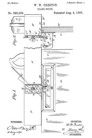
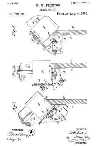
Figure 1 is a side elevation showing my improved plane-guide attached to a plane, as in use in squaring the edge of a board. Fig. 2 is a rear end sectional view of the same. Fig. 3 shows in end view the plane and its guide adjusted to bevel the edge of a board downward toward its finished face. Fig. 4 is an end view with the plane and its guide adjusted to utilize the outer part of the sharp edge of the plane-iron; and Fig. 5 is an end view illustrating the adjustment of the plane and its guide for beveling the edges of boards downward and backward from their finished faces.
The plane-guide in its preferred form consists, mainly, of three meta! parts: the fence A, or guide proper, the plate B, which is to be fixed to the side of the plane-stock, and the part C, which connects the parts A B by the aid of thumb-screws in the various adjustments of the plane-guide, as hereinafter more fully explained.
The fence A consists of a plate, A’, made either solid throughout or cut away at various places to decrease its weight, and having a strong flange, D, projecting at a right angle and in vertical plane from its back or outer face, and preferably from about the center of the plate A’ (See Fig. I.) I prefer to make the plate B with flanges b b at opposite edges, and to form a boss, b’, at the center of its face, to give sufficient body of metal to firrnly hold a thumb-screw, E, which is threaded into the boss. I attach the plate B by screws f, or otherwise, and it may be permanently, to the side of the stock F of the plane, and preferably near where the plane-iron or cutter G passes through the working-face H of the plane, and so that the flanges b b range up and down the side of the plane. The connecting-piece C is made with an upper portion, I, fitted to slide on the plate B between its flanges b b, and having a slot, i, through which the screw E passes, the flange or shoulder e of the screw being wider than the slot, so it may bind the part I to the plate B at any desired adjustment. The lower part, J, of the connection C is in the form of a flange which projects to one side or face of the upper part I, and in a plane at a right angle with said part, I, and so part J may lie face to face with the flange D of the fence A and be fastened to it by the thumb-screws K L, the screw K serving, when loosened, as a pivot on which to swing the parts A C to their various angles of adjustment, and the screw L, which passes through a curved slot, M, of plate D, serving, with the tightened screw K, to bind the parts C A firrnly together when set. The screws K L enter threaded holes in the lower part or flange, J, of the connection C. I cut away the upper edge of the fence-plate A’, as at a, and for a depth a little greater than the maxirnum projection of the plane-iron G from the plane-face H, so that said face always may lie closely on the upper edge of the fence-plate, and the pivot-screw K is located in such relation to the parts A C of the plane-guide that the corner of the plane-iron nest the guide always will project inward beyond the contacting faces of the fence A and the board O to be jointed, as seen best in Figs. 2 and 3. The adjustment and operation of my improvement are as follows: In jointing the edges of boards O squarely with their finished face o, against which the fence-plate A is held and moves as the plane is operated, or in jointing at a slight back bevel or undercut suitable for the edges of base-boards, door-jambs, and the like, or in jointing at any bevel from forty-five degrees (more or less) downward toward the face o of the work, the part C will be adjusted with its lower part or flange, J, outward, so that the screw K may be entered into the threaded hole 1 of said flange, as shown in Figs. 2 and 3. In square-jointing the boards the fence-plate A’ will be set square with the edge of the plane-iron when the screw E binds the parts C B together, so that the plane-face H rests on the top of the fence-plate A’, as seen in Fig. 2, and the screw L then will be passed through the slot M into the threaded hole 2 of the flange J, and the screws K L then are tightened and the plane is ready for work. To bevel the edge of the board O under slightly toward the back, the screws E K L will be loosened and the plane will be swung over to the right hand on pivot K, or the fence A swung under the plane to the desired angle, and the screws K L will be tightened. The loose screw E, which had allowed the plate B to lift or draw upward on the part I of connection C, will then be tightened, when the plane-face H rests on the upper edge of the fence-plate A’, and the plane is ready for work. To bevel the edge of the board O downward toward its face o, the screws K L will be loosened, and the connection C and the plane will be swung downward to the left hand, the screw L then moving through the slot M, and when the plane-face H stands at the desired angle with the working-face of the fence-plate A’, the screws K L will be tightened; but this adjustment throws the plane-face H away from the fence-plate A’, and to bring them in contact the screw E will be loosened, so that the part I of connection C may be slid upward, or the plane and its plate B be slid downward until the plane-face H rests against the top of the fence-plate A’, the flange D being out away at d to allow this adjustment, and the screw E then will be tightened and the plane is ready for work, as seen in Fig. 3, which shows the tool set to joint the edge of the board at an angle of forty-five degrees; but the adjustments to work at angles greater or less than that shown may readily be made as the work to be done shall require. In squaring or slightly back-beveling the edges of the boards, with the pivot-pin K entered in the screw-hole 1 of the flange J, as in Fig. 2, the left-hand side or edge portion, g, of the plane-iron G will be used, and to provide for utilizing the right-hand sharp edge portion, g’, of the iron when the portion g becomes dulled by use so as to avoid frequent whetting or sharpening of the iron, and also to provide for jointing the boards at a considerable back bevel, the connection C will be reversed in position, and the pivot-screw K will be entered into the screw-hole 2, and the screw L will be turned into the screw-hole 3 of the flange portion J of connection C, as in Figs. 4 and 5. In squaring the edges with the part g’ of the plane-iron, as in Fig. 4, the screws K L will be tightened when the screw L is at or near the lower part of the slot M of flange D; but in setting the plane over to joint at a back downward bevel at any desired inclination from a square edge to an angle of forty-five degrees or more, the screw L will move upward in the slot M, more or less, as required, and the screw E will be tightened when the face H of the plane rests on the top edge of the fence-piece A’. In Fig. 5 the plane is set to back-bevel the lumber at an angle of forty-five degrees.
It will be seen that in every described adjustment of the plane and guide the plane-face is in contact with the guide fence-piece A’, and that it only is necessary in using the plane to hold the fence-piece flat against the finished face of the lumber to secure accurately squared or beveled edges of the lumber, and without the inconveniences and delays incident to the use of try-squares or bevels, thus enabling the workman to do more accurate work and a largely-increased amount of it in a given time.
If desired, the plate B may be let in flush with the side face of the plane, and when a plane is to be used for squaring or for beveling at one angle only, the plate B may be dispensed with and the upper plate or part, I, of the connection C will then be fastened directly to the side of the plane-stock; but the use of the plate B and screw E is preferred for securing the various adjustments allowed by them with a single plane, as above described.
Any suitable fastenings may be substituted for the thumb-screws K L which will serve their purpose — such as nutted bolts; but the thumb screws are preferred because of their convenience in effecting the adjustments of the plane-guide.
Having thus described my invention, what I claim as new, and desire to secure by Letters Patent, is —
1. A plane-guide comprising a fence, A, formed of a plate, A’, having a flange, D, provided with a curved slot, M, and a set-screw, K, passing through the said flange in the same horizontal plane as the upper end of the slot, a reversible connecting-piece, C, formed with the lower flange, J, and upper plate, I, in planes at right angles to each other, the said flange J having holes 1 and 2 in horizontal alignment, and the set-screw L, whereby the set-screw K may serve as a pivotal point and the set-screw L the adjusting point to allow of adjustments, substantially as set forth.
2. A plane-guide comprising a fence, A, formed of a plate, A’, having a flange, D, provided with a curved slot, M, and a set-screw, K, passing through the said flange in the same horizontal plane as the upper end of the slot, a reversible connecting-piece, C, formed with the lower flange, J, and upper plate, I, in planes at right angles to each other, the said flange J having holes 1 and 2 near its upper edge in the same horizontal plane, and a hole, 3, near its lower edge, and the set-screw L, adapted to engage either one of the said holes, for adjustment when one of the other holes is engaged by the set-screw K as a pivotal point.
3. In a plane-guide, the combination, with the fence A and its flange D at right angles therewith, of the reversible connecting-plate C, having a flange, J , in the plane of flange D, and adljustably pivoted to said flange D, and a binding-screw for locking said parts in their adjusted positions, substantially as set forth.
WILLIAM WALLACE PRESTON.
Witnesses:
WM. H. BENEDICT,
GEO. T. CULVER.