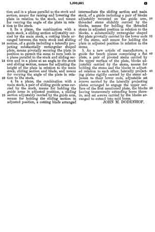
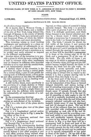
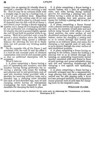
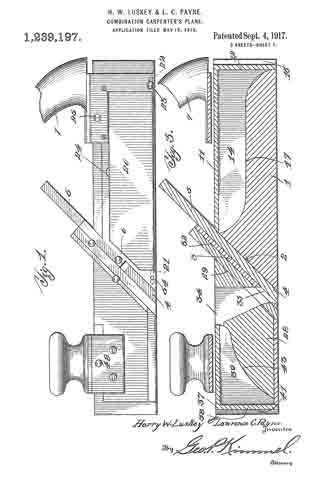
No. 1,412,609 – Gauge For Carpenter’s Planes And The Like (George Eger) (1922)

[paiddownloads id=”731″]1412609


UNITED STATES PATENT OFFICE.

_________________

GEORGE EGER, OF PLAINVILLE, CONNECTICUT, ASSIGNOR TO THE STANLEY WORKS,
OF NEW BRITAIN, CONNECTICUT, A CORPORATION OF CONNECTICUT.

GAUGE FOR CARPENTER’S PLANES AND THE LIKE.

SPECIFICATION of Letters Patent No. 1,412,609, dated December 18, 1855.
Application filed December 18, 1880. (No model.)

1,412,609. Specification of Letters Patent. Patented April 11, 1922.
Application filed June 6, 1920. Serial No. 475,240.

_________________

To all whom it may concern:

Be it known that I, GEORGE EGER, a citizen of the United States, and a resident of Plainville, county of Hartford, State of Connecticut, have invented certain new and useful Improvements in a Gauge for Carpenters’ Planes and the like, of which the following is a specification.

The present invention relates to a gauge or fence for use in connection with a combination tool or plane of the type for forming beads, grooves and all kinds of moldings, and the aim of the invention is to provide a gauge of this kind with means for preventing it from being thrown out of set adjustment or alinement relative to the cutter.

In the accompanying drawing:

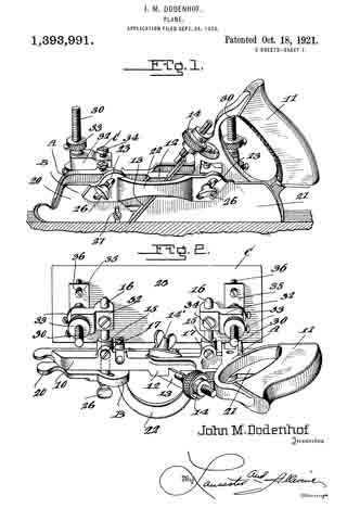
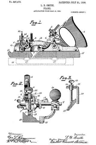
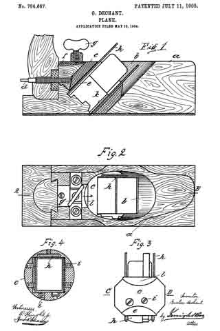
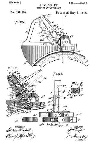
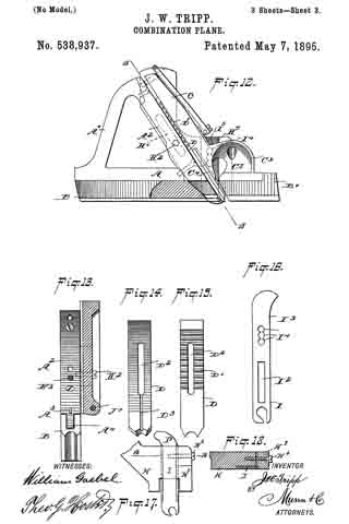
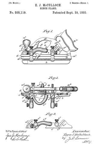
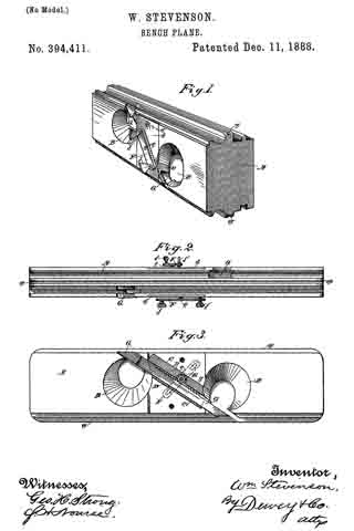
Fig. 1 is a perspective view of a plane or carpenters plow to which the improved gauge of the present invention is applied.

Fig. 2 is a fragmentary view looking at the front of the plane.

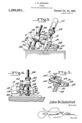
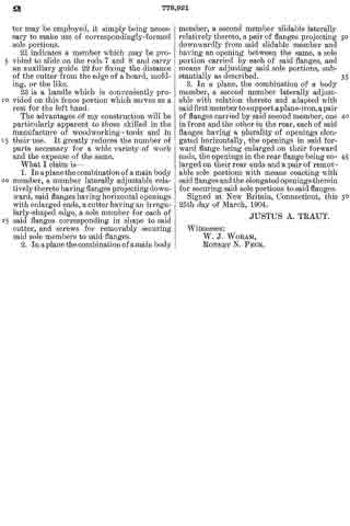
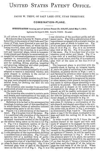
Fig. 3 is a perspective view of my improved gauge or fence.

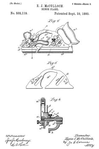
The plane or plow shown in Fig. 1 is of an old and well known type and, as here shown, the parts are set up or adjusted to form a bead on the corner or edge of a matched timber, shown in dotted lines Fig. 1. The plane in its main parts comprises a main stock a provided with a runner b and a handle c. d is a sliding section adjustably supported on arms e and carrying an adjustable runner f. The letter g denotes the cutter which is adjustably supported on the main stock a.

The gauge or fence to which the present invention particuiarly relates comprises an upper plate 10, a lower piate 11 adjustably connected thereto, and a post 12 extending into a socket or opening in a housing 13. The post is clamped in this socket by means of a thumb screw 14. In the present instance, the lower plate is connected to the upper one by screws 15, and the openings 16 in the upper plate 10 through which these screws extend are elongated so as to allow for adjustment of the lovver plate 11.

The present invention resides in providing for such interengagement between the gauge and one of the runners that the gauge is secureiy held against movement or displacement from its properly adjusted position. In the present instance, this result is accomplished by providing in the upper face of the plate 11 and adjacent its active edge a longitudinally extending groove or slot 17 which is adapted to receive the lower edge of one of the runners, in the present instance runner f.

As previously stated, the parts of the plow are shown as being adjustably set up to form a bead along the edge or corner of a matched timber. The gauge is so set that the edge of the plate 11 engages the side face of the timber so that the gauge acts in the nature of a fence or guide. The inner edge of the plate 11 is immediately beneath the inner point of the cutter g so that the round of the bead will merge without a break or shoulder into the straight face out the timber. In the absence of the groove 17, it has been found that in operation considerable difficulty and trouble have been experienced in that owing to the pressure which must be exerted to keep the edge of the plate 11 flush against the side edge of the timber, the gauge will tend to turn in the housing 13 resulting in faulty work. This difficulty is obviated by providing the groove 17 in the plate, for it will be seen that when the edge of the runner engages in this groove, the plate is securely anchored and is effectively prevented from turning or twisting or being forced out of alinement.

I claim as my invention :–

1. A gauge or fence for use in connection with a plane having a runner, including a vertical post, a plate carried by said post, and means on said plate adapted to cooperate with said runner for anchoring said plate against lateral displacement relative thereto.

2. A gauge or fence for use in connection with a plane having a runner, including a plate having a groove adapted to receive the bottom edge of the runner, and means for connecting said piate to the plane.

3. A. gauge for use in connection with a plane having a runner, including a post, a plate adjustably connected to said first plate and having a longitudinally extending groove adjacent one edge adapted to receive the bottom edge of the runner of the plane.

4. In combination a plane having a runner and a socket; and a gauge including a post secured in said socket, a plate carried by said post, and means on said plate adapted to cooperate with said runner for anchoring said plate against lateral displacement relative thereto.

GEORGE EGER.

No. 1,393,991 – Plane (John M. Dodenhof) (1921)

[paiddownloads id=”729″]1393991


UNITED STATES PATENT OFFICE.

_________________

JOHN H. DODENHOF, OF ST. LOUIS, MISSOURI.

PLANE.

_________________

1,393,991. Specification of Letters Patent. Patented Oct. 18, 1921.
Application filed September 24, 1920. Serial No. 412,431.

_________________

To all whom it may concern:

Be it known that I, JOHN M. DODENHOF a citizen of the United States, residing at St. Louis, in the county of St. Louis and State of Missouri, have invented certain new and useful Improvements in Planes, of which the following is a specification.

This invention relates to planes for dove-tailing tongue and grooving, dado work and the like, and the primary object of the invention is to provide an improved attachment for planes of this character, which is so constructed that dove tail tongue and grooving can be cut at any angle in an expeditious and simple manner.

Another object of the present invention is to provide an improved guide for dove tail tongue and grooving work and the like, which will hold the plane and its cutting blade at the correct and desired angle, the guide being so arranged and associated with the main stock of the plane in such a manner as to permit the same to be swung at any angle and at any distance from the main stock.

A still further object of the invention is to provide an improved sliding section for the main stock of the plane, so as to permit various sizes and shapes of cutting blades to be used with the plane, the sliding section being formed in separate pieces which are adjustable toward and away from the work, and toward the main stock.

A still further object of the invention is to provide an improved attachment for planes of the above character, which will be durable and efficient in use, one that will be simple and easy to manufacture, and one which can be placed upon the market and associated witii planes at a reasonable cost.

With these and other objects in view, the invention consists in the novel construction, arrangement and formation of parts as will be hereinafter more specifically described, claimed and illustrated in the accompanying drawings, forming a part of this specification, in which drawings:

Figure 1 is a side elevation of the improved plane showing the same in use, the work being shown in longitudinal section.

Fig. 2 is a top plan view of the plane and its attachment.

Fig. 3 is a front elevation of the plane and its attachment showing the use of the same for making dove tail grooves, the work being shown in transverse section.

Fig. 4 is a fragmentary side elevation of the plane and attachment looking in the opposite direction from Fig. 1, illustrating the position of the plane and attachment when in use, the work being shown in section, and

Fig. 5 is a detail transverse section taken through the main stock and sliding section illustrating the means of adjustably connecting the sliding section with the main stock.

Referring to the drawings in detail, wherein similar reference characters designate corresponding parts throughout the several views, the letter A indicates the plane, B, its sliding section, and C, the improved adjustable guide therefor.

The plane A may be of the usual or any preferred form and of any desired make, or of the type utilized for making dove tails, tongue and grooving, dado work and the like. As shown the plane A includes the main stock 10 having the handle 11 arranged on one end of the same. The main stock 10 is provided with the usual cutting blade or tool guide 12 for the tool or blade 13. As shown the guide is arranged at an angle to the vertical in the usual manner and is provided with the usual holding blade nut and bolt 14’. As shown the bolt extends transversely of the stock. The handle 11 supports at its forward end the usual adjusting device 14, which may be of any preferred construction. The main stock 10 is provided with the straight laterally extending hollow bosses 15, which slidably support the guide arms 16, which are held in their preferred adjusted positions by means of set screws or the like 17. These arms 16 may be of any preferred length and are utilized for supporting the sliding section B and the improved attachment C.

The improved sliding section B of the plane is constructed similar to the usual sliding sections for planes of this character, with the exception that the same is constructed in three sections, namely, the forward body section 20, the rear body section 21 and the connecting bridge piece 22. The body sections 20 and 21 are formed of any preferred material and are in direct vertical alinement with each other and are adapted to receive between the same the cutting blades or tools which are carried by the main stock 10. The forward edge of the body piece 21 of the sliding section B is inclined to conform to the inclination of the guide 12 for the cutting tool or blade.

The bridge piece 22 may be connected to the body sections 20 and 21 in any preferred manner, and if so desired the terminals thereof may be welded or brazed to the body section. As shown the bridge piece 22 is substantially arcuate shaped in plan and is so shaped as to permit blades or cutting tools of various widths to be used. The body pieces 20 and 21 are provided with inclined guide slots 23, which slidably receive the flattened or polygonal shaped terminals 25 of the guide arms 16. It can be seen that the slidin section B may be raised or lowered according to the depth of the groove, tongue or the like being made. To hold the sliding section B in its adjusted position, the flattened or polygonal shaped terminals 25 of the guide arms 16 are provided with threaded bores for the set screws 26 which are adapted to frictionally engage the outer surface of the sliding section B. If so desired the sliding section B may be provided with the swinging spur 27 for cross grain work.

The improved attachment or side section C includes the flat rectangular shaped plate or bottom 28, which is adapted to engage the work and hold the main stock 10 with its cutting blade or tool at the desired angle for making the desired dove tail groove or tongue. The upper surface of the base plate or bottom 28 is provided adjacent to its opposite ends with the upstanding ears 29 which are connected to the lower terminals of the adjusting screw threaded stems 30 by means of pivot ins or the like 31. These screw threaded adjusting stems 30 are slidably carried by blocks 32 which are provided with transverse bores for the reception of the guide arms 16. It can be seen by referring to Fig. 2 of the drawings that the blocks 32 project laterally from the guide arms 16 and are adjustably mounted thereon toward or away from the main stock 10. These blocks are held in their adjusted positions on the guide arms by means of set screws or the like 34. It is to be also noted that not only are the guide arms themselves adjustable but that the blocks 32 are adjustably mounted thereon.

The screw threaded guide stems 30 are, as stated, slidably carried by the blocks 32 and these stems are held in their adjusted positions by means of upper and lower lock nuts 33 which are threaded on the stems into engagement with the opposite sides of the blocks. The lower terminals of the stems 30 are provided with the outwardly extending rigid plates 35, which adjustably support the screw threaded members 36, which are adapted to engage the upper surface of the guide plate or bottom 28 for holding the same at the desired angle in relation to the main stock 10 of the plane A. These screws 36 are held in their adjusted position by means of nuts 37 which are threaded thereon into engagement with the plates 35.

In operation of the plane and guide, the desired tool or cutting blade is placed in the guide 12 in the usual manner and the blade or tool is adjusted by means of the device 14. The sliding section B is then adjusted toward the blade by means of the sliding arms 16 until the section is at the desired point. The guide plate or bottom 28 is then slid on the guide arms 16 to the desired point and held in place by means of the set screws 34 provided for that purpose, after which the plate or bottom 28 is swung to the desired angle at which the dove tail grooves or tongues are to be made on the pivot pins 31, after which the set screws 36 are adjusted so as to hold the plates or bottoms in this position. The plate or bottom engaging the work will effectively hold the main stock 10 and its cutting blade at the desired angle and the dove tail will be made with the desired inclination to the walls thereof. The depth of the groove to be made can be determined by the distance on the plate 28 from the tool and this distance can be varied as desired by means of the threaded stem 30. If so desired, the position of the plate 28 can be changed from one side to the other to suit varying conditions.

The plane, if so desired, can also be used with the usual sliding section and fence (not shown) for rabbeting or the like, but the same forms no part of this invention.

Changes in details may be made without departing from the spirit or scope of this invention; but, I claim:

1. In a plane, the combination with a main stock, a sliding section adjustably carried by the main stock and arranged in parallel relation to the main stock, a cutting blade arranged between the sliding section and the main stock, of a guide including a laterally projecting pivoted plate arranged to turn both in a plane at right angles to the stock and in a plane parallel to the stock and sliding section, and means for varying the angle of the plate in relation to the main stock, sliding section and blade.

2. In a plane, the combination with a main stock, a sliding section adjustably carried by the main stock and arranged in spaced parallel relation thereto, a cutting blade arranged between the main stock and sliding section, of a guide including a laterally projecting plate adjustably toward and away from the main stock, means pivotally securing the plate in position to permit the same to turn both in a lane at right angles to the stock and sliding section and in a plane parallel to the stock and section, means for raising and lowering the plate in relation to the stock, and means for varying the angle of the plate in relation to the stock.

3. In a plane, the combination with a main stock, a sliding section adjustably carried by the main stock, a cutting blade arranged between the main stock and sliding section, of a guide including a laterally projecting substantially rectangular shaped plate, means pivotally securing the plate in position to permit the same to turn both in a plane parallel to the stock and sliding section and in a plane at an angle to the stock and sliding section, means for adjusting the height of the plate in relation to the main stock, sliding section and blade, and means for varying the angle of the plate in relation to the stock.

4. In a plane, the combination with a main stock, a pair of sliding guide arms carried by the stock, means for holding the guide arms in adjusted position, a sliding section adjustably carried by the guide arm, means for holding the sliding section in adjusted position, a cutting blade arranged intermediate the sliding section and main stock, of a guide including a pair of blocks adjustably mounted on the guide arm, threaded stems slidably carried by the blocks, means for holding the threaded stems in adjusted position in relation to the blocks, a substantially rectangular shaped flat plate pivotally carried by the lower ends of the stems, and means for holding the plate in adjusted position in relation to the stems.

5. As a new article of manufacture, a guide for bench planes comprising a flat plate, a pair of pivoted stems carried by the upper surface of the plate, blocks adjustably carried by the stems, means for holding the stems and the blocks in adjusted relation to each other, laterally projecting plates rigidly carried by the stems adjacent to their lower ends, adjustable set screws carried by the laterally projecting plates arranged to engage the upper surface of the first mentioned plate, the blocks having transversely extending bores therein, and set screws carried by the blocks arranged to extend into said bores.

JOHN M. DODENHOF.

No. 1,279,263 – Plane (William Clark) (1918)

[paiddownloads id=”721″]1279263


UNITED STATES PATENT OFFICE.

_________________

WILLIAM CLARK, OF NEW YORK, N. Y., ASSIGNOR OF ONE-HALF
TO JOHN T. HILBERT, OF LONG ISLAND CITY, NEW YORK.

PLANE.

_________________

1,279,263. Specification of Letters Patent. Patented Sept. 17, 1918.
Application filed February 19, 1918. Serial No. 218,115.

_________________

To all whom it may concern:

Be it known that I, WILLIAM CLARK, a citizen of the United States, and a resident of the city of New York, Long Island City, borough of Queens, in the county of Queens and State of New York, have invented a new and Improved Plane, of which the following is a full, clear, and exact description.

This invention relates to wood working implements and particularly to a plane capable of a plurality of adjustments to accomplish different purposes, and has for an object the provision of such a structure as to be quickly and easily adjusted to respond to the different requirements.

Another object of the invention is to provide a plane in which the main cutting blade is held in runways while other implements may be clamped on different sides provided therefor so as to coact with the central blade, or act independently thereof.

A further object of the invention is the provision of a plane having a central guide for a central blade, a pair of side guides for cutting tools of different kinds, a front guide and offset portions on the sides for allowing the side implements to act as beading tools, grooving tools, and the like.

A still further object, more specifically is the provision of a single skeleton or frame and a plurality of tools and clamps associated therewith whereby a single frame can be used with the different tools necessary for substantially all requirements of a carpenter.

In the accompanying drawing:

Figure 1 is a top plan view of a plane disclosing an embodiment of the invention.

Fig. 2 is a side view of the plane shown in Fig. 1.

Fig, 3 is a bottom plan view of the plane shown in Fig. 1.

Fig. 4 is a longitudinal vertical section through the plane shown in Fig. 1, same being taken on line 4–4.

Fig. 5 is a transverse sectional view through Fig. 1 on line 5–5.

Fig. 6 is a fragmentary detail sectional view through Fig. 4 on line 6–6.

Referring to the accompanying drawing by numerals, 1 indicates a frame or skeleton of a plane, which plane is provided with a smooth bottom 2 and offset portions 3 and 4, said offset portions being utilized when one of the side tools is being used as a beading tool, or when a piece of material is being specially formed. The body 1 is provided with a pair of grooves 5 and 6 in which the blade 7 is slidingly positioned, said blade being clamped in any desired adjusted position by a thumb screw 8 which extends through a transverse bar 9 connected at the ends to the body 1 or formed integral therewith. The blade 7 extends for almost the full width of the bottom 2 and projects through a comparatively large opening 10, and the grooves 5 and 6 causing the blade to extend through the opening in such a manner, as there will be provided a passageway 11 in front of the cutting edge 12 of the blade and a passageway 13 at the rear of the blade. The side walls of frame 1 are cut away at 14 which is opposite the cutting edge 12 whereby chips, shavings and the like cannot become wedged beneath the blade or between the blade and the side walls. As the blade 7 moves upwardly and downwardly in the guiding grooves 5 and 6 the cutting edge is always true in respect to the bottom 2 so that a proper shaving will be produced when this blade is in use.

At the front part of the frame 1 a transverse plate or section 15 is provided which may be independent of the frame or formed integral therewith, said section having a slot 16 extending transversely of the body 1 as shown more particularly in Fig. 1. A thumb screw 17 extends through this slot and also through the slot 18 in the tool 19, slot 18 extending at right angles to slot 16. A nut 20 is normally positioned on the end of screw 17 so that when the tool 19 has been properly adjusted vertically and also horizontally thumb screw 17 may be tightened and tool 19 clamped in place. The nut 20 may be of the ordinary type, but is preferably provided with overhangin shoulders 21 projecting on each side of the tool 20. The tool 19 may be used for providing a central bead, rabbit, or any other desired structure and preferably extends through an aperture in the bottom 2 centrally thereof as shown in Fig. 4 so that there will be a passageway both in front and back of the tool as well as on both sides, as the aperture 22 usually extends for the full width of the section 15 though the tool may be positioned so as to operate substantially at any point in front of the blade 7. On one side of the frame 1 is positioned the offset 3 which merges into an opening 23 whereby there is provided a shoulder 24 for receiving a tool 25. Tool 25 may be an ordinary blade with a straight edge or may be a beading tool, or a tool of any preferred kind. Regardless of the form of the cutting edge 26 on tool 25 said tool is held in place by a thumb screw 27 threaded into the side wall 28 of frame 1, said thumb screw having a thumb engaging member and a flange 29 overlapping the tool 25, but preferably not overlapping shoulder 24 whereby the tool is pressed tightly against the wall 28 and held in position while in operation. Wall 28 is provided with a boss 30 spaced a short distance above the shoulder 24, said shoulder being spaced a sufficient distance for allowing the tool 25 to freely slide, but will prevent any twisting motion thereof.

On the opposite side of the frame 1 and associated with the wall 31 and the offset 4 is a tool 32 and associate parts of identical construction with tool 25 and associate parts so that no additional description will be necessary.

What I claim is:

1. A plane comprising a frame having a pair of upstanding side members, said side members having facing guideways for receiving a planing tool, means for holding said planing tool in said guideways, each of said side members being provided with a shoulder for receiving auxiliary tools, and a threaded lug, a clamping screw threaded into each of said threaded lugs, each of said clamping screws having an enlargement overlapping the tools supported by said shoulders for clamping the tools in place.

2. A plane comprising a frame having a smooth bottom and a pair of upstanding sides, said sides having facing inclined grooves for receiving a planing tool, said bottom having a notch at the base of said grooves merging into said grooves, and means for locking a planing tool in said inclined grooves.

3. A plane comprising a frame formed with a smooth bottom and a pair of upstanding sides, the juncture of said sides and said bottom being formed with offsets or shouldered portions, the outer surface of said shouldered portions being parallel with said bottom, means for clamping a cutting tool so as to extend through said bottom and operate as an ordinary plane, and means for clamping a tool against each of said sides so as to project through the outer surface of said shouldered portions.

4. A plane comprising a frame having an opening in the bottom, means for holding a planing tool so as to extend through said opening, an upstanding transversely slotted member connected with said frame in front of said opening, and means adjustable along said slot and extending therethrough for clamping a tool against said upstanding member.

5. A plane comprising a frame having a centrally arranged seat for a comparatively large planing tool, side seats adjacent said central seat for side planing tools, a front tool seat arranged centrally, and independent means adjacent each of said seats for clamping tools on the respective seats.

WILLIAM CLARK.

_________________

Copies of this patent may be obtained for five cents each, by addressing the “Commissioner of Patents, Washington, D. C.”
_________________

No. 1,239,197 – Combination Carpenter’s Plane (Harry W. Luskey And Lawrence C. Payne) (1917)

[paiddownloads id=”718″]1239197


UNITED STATES PATENT OFFICE.

_________________

HARRY W. LUSKEY AND LAWRENCE C. PAYNE, OF PENSACOLA, FLORIDA.

COMBINATION CARPENTER’S PLANE.

_________________

1,239,197. Specification of Letters Patent. Patented Sept. 4, 1917.
Application filed May 18, 1916. Serial No. 98,401.

_________________

To all whom it may concern:

Be it known that we, HARRY W. LUSKEY and LAWRENCE C. PAYNE, citizens of the United States, and residents of Pensacola, in the county of Escambia and State of Florida, respectively, have invented certain new and useful Improvements in Combination Carpenters’ Planes, of which the following is a specification.

The present invention relates to new and useful improvements in wood-working tools and has particular reference to an improved type of bench-plane.

The primary object of our invention is to provide a plane of the class described having a combination of elements associated therewith whereby to adapt the plane for various uses other than those to which the usual benchplane is limited.

Another object of our invention is to provide a plane formed in a plurality of sections, said sections having associated therewith extension and adjustment members for permitting the adaptation of the plane to use as an ordinary plane or to permit the use of the device as a circular plane or the like.

A further object of our invention is to provide a plane of the class described, having a removable cutting element, reversible extensions, and means for retaining said entensions in their various positions.

A still further object of our invention is to provide an improved plane of the class described, having an improved type of gage for use in connection with the plane.

A still further object of our invention is to provide a plane of the class described which is simple in construction, strong and durable, cheap to manufacture and effective in operation.

Other objects and advantages to be derived from the use of our improved plane will appear from the following detail description and the claims, taken with an inspection of the accompanying drawings, in which :

Figure 1 is a side elevational view of a plane embodying the improvements of our invention;

Fig. 2 is a top plan view of the same;

Fig. 3 is a longitudinal sectional view taken on the line 3–3 of Fig. 2 looking in the direction of the arrow;

Fig. 4 is a transverse vertical sectional view taken on the line 4–4 of Fig. 2 looking in the direction of the arrow;

Fig. 5 is a similar view taken on the line 5–5 of Fig. 2 looking in the direction of the arrow;
Fig. 6 is a reduced perspective view of our improved plane showing the same in use; and

Fig. 7 is an enlarged perspective view of the cutting element removed and in use as a chisel.

Referring more particularly to the drawings, wherein similar characters of reference designate like and corresponding parts throughout the various views, 1 designates the main body of our improved plane, said body being provided with an inclined front wall 2 having a plate 3 rigidly associated therewith. The cutting member of the plane is shown and is composed of a blade 4 having a shank 5 extending therefrom, said shank 5 lying on the inclined wall 2 beneath the plate 3. A set screw 6 is provided for adjustably maintaining the blade 4 in desired position. its best shown in Fig. 5 the body is provided with a manipulating handle 7 carried on a laterally extending arm 8 provided with a downturned portion 9 secured to the body 1 by means of screws 10 or the like. A rear extension member R is provided, the same having a right-angle wall portion 19, the main portion or sole 11 being provided with dove-tailed flanges 13 engageable with complemental recesses formed on the top portion of the body 1. The strengthening web 14 is cast integral with the main portion and the wall 12. The outer face of the wall 12 is provided with dove-tailed flanges 15 for engagement, at times, with complementally formed recesses on the marginal end edges of the body 1. This is best shown in Fig. 2, one corner of the member 11 being broken away to illustrate one of the dove-tailed recesses which is designated 16. Of course, a slot or recess 17 is provided in the body 1 to accommodate the strengthening web 14.

The one side portion of the body 1 is provided with a recess 19 at the base of which is hingedly mounted an angle-gage 20. The angle-gage is mounted on trunnions 21 and 29. extending from the free end thereof and arranged in complemental openings in the body. A set screw 23 serves to maintain the gage 20 in the angle to which the same has been set, said screw engaging the trunnion 22 as best shown in Fig. 1. A recess 24 is provided in the body 1 adjacent the upper marginal edge of the gage 20 for facilitating engagement of the user’s finger with said gage to remove the same from the recess. A set screw 25 serves to prevent accidental dislodgment of the member 11.

We provide a front section for the plane, said section including a body 28 having a diagonal rear wall 29 having dove-tailed flanges 30 along the marginal edges thereof. The flanges 30 serve to form a sliding engagement with complementally arranged recesses 31 formed along the marginal edges of a plate 32, said plate being in turn engaged with the plate 3 hereinbefore referred to, said plate 32 and plate 3 being detachably engaged, the dove-tailed engagement being indicated at 33. The body 28 is provided with a tapering opening 34, said opening being adapted to aline with registering openings 35 formed in the plates 3 and 32.

A front extension member is provided and is formed with a main body portion or sole 37 and a right-angle wall portion 38, said portions being strengthened by a web 39, the marginal edges of the portion 37 being formed with dove-tailed flanges 40 for engagement with complementally arranged dove-tailed recesses 40’ formed on the body 28. The outer face of the wall 38 is provided with flanges 41 for engagement with recesses 42 formed in the end portion of the body 28, said engagement being best shown in Fig. 6. A suitable recess 43 is provided in the body 38 for accommodating the web 39.

A knob or handle 44 is provided, carried on a bracket 45, having a downturned portion 46 secured to the side of the body 28 by means of screws 47 or the like. A set screw 48 carried in the downturned portion 46 of the bracket 45 serves to engage the member 37 to prevent dislodgment of the same. The base of the body 28 is provided with marginally arranged dove-tailed recesses 49, a plate 50 being receivable on the bottom of said body and being formed with dove-tailed flanges 51 for engagement with said recesses. The flanges 51 are also engageable, at times, with the recesses 42 formed on the end of said body for a purpose which will hereinafter appear.

We provide a gage for use in connection with the plane, said gage including a rod 53 adapted for threaded engagement with an opening 54 provided in the body 1 of the plane, said rod extending laterally therefrom. A slidable gage member 54’ is carried on the rod, said gage member being provided with a flange 55 for engagement with the marginal edge of the work, a set screw 56 being provided for engagement with the rod 53, whereby to lock the gage member at a desired point on said rod.

It will thus be seen that in our improved plane we have provided a device, which owing to the detachable association of the parts provided, is capable of use in connection with various classes of work. The plane may be used as an ordinary plane, and when used in this capacity the parts are associated as shown in Fig. 1. Should it be desired to use the plane as a nose plane the front portion 28 is removed, the plate 32 being permitted to remain in position on the portion 1. This permits the plane to reach otherwise inaccessible points owing to the absence of any extension interfering with the blade 4. Should it be desired to lengthen the plane the extensions 11 and 37 may be applied to the sections 1 and 28, respectiveiy, as shown in Fig. 6. A set screw 58 is provided on the wall 12 of the section 11, said set screw engaging the end of the body 1 and maintaining the extension 11 against vertical movement when applied as shown in Fig. 6. A similar set screw 59 is provided in the wall 38 of the extension 37 for a purpose similar to that of the screw 58.

The function of the gage 54 will be best apparent in using the device as a nose plane as hereinbefore set forth, said gage serving to engage the marginal edge of the work for guiding the plane.

The plane is also adapted for use on curved surfaces, either convex or concave. When using the plane on a convex surface, all of the parts are shown in Fig. 1, with the exception of the extension 37 and the plate 50. The extension 37 is removed entirely and the plate 50 substituted therefor, the lower end of the plate 50 extending below the under surface of the plane body to guide the same when moving over a convex surface.

In using the device for concave work all of the parts are maintained as shown in Fig. 1 with the exception of the relative positions of the bodies 1 and 28, in this instance the body 28 being moved upwardly relative to the body 1 so as to expose the knife blade A for engagement with the concave surface over which the plane is operating.

Referring to Fig. 7 the peculiar construction of the blade at permits of ready removal from the plane, the shank 5 being adapted to engage a suitable handle 60 adapting the blade to use as a chisel. Thus it will be seen that we have provided a plane which is applicable for use in connection with various classes of work, the novel arrangement of the elements permitting a wide range of adjustment. A spirit level 61 is provided in one wall of the body 1 for an obvious purpose.

The plane is also adapted for use on laterally beveled surfaces, the angle-gage 20 being adapted to be set at various angles relative to the plane body for this purpose.

It is thought that the detail construction and arrangement of the parts of our improved plane will be apparent from the foregoing description taken in connection with the accompanying drawings, the simplicity and durability of said structure being one of its greatest advantages over the prior devices of this character. It is, of course, to be understood that the various parts of the device may be cast, suitable milling being employed to cause the dove-tailed grooves and the like to snugly engage.

While we have described our invention and shown the same as embodying a specific structure, it is of course, to be understood that we do not limit ourselves to this structure, but reserve the right to make such changes in the same as do not depart from the spirit and scope of the invention as claimed.

Having thus fully described our invention, what we claim as new and desire to secure by Letters Patent, is :–

1. in a bench plane including a body portion, the forward and rearward ends of the body being provided with dove-tailed flanges, extension members having complementally formed recesses therein to receive said flanges, the extensions being vertically adjustable relative to the body, and the extensions being adapted to be housed upon the body when detached from the ends.

2. In a bench plane including a body portion, the forward and rearward portions of the body being provided with longitudinally extending slots, extension members detachably associated with the forward and rearward portions of the body, webs formed on each extension member adapted to be received in said slots when the extensions are detached from the forward and rearward portions of the body.

3. In a bench plane including a body portion, the forward and rearward portions of the plane being provided with a longitudinally extending slot, an extension member adapted to be detachably associated with the forward and rearward end portions of the plane, a web formed on said extension ment ber, the sole of the extension member being adapted to be retained in alinement with the sole of the plane when used as extensions, the webs adapted to be received in said slots when the extensions are detached from the ends of the plane, the under surface of the extension soles being adapted to engage the upper surface of the plane.

In testimony whereof, we affix our signatures hereto.

HARRY W. LUSKEY.
LAWRENCE C. PAYNE.

_________________

Copies of this patent may be obtained for five cents each, by addressing the “Commissioner of Patents, Washington, D. C.”
_________________

No. 968,508 – Wood-Scoring Device For Planes And The Like (Christian Bodmer) (1910)

[paiddownloads id=”673″]968508


UNITED STATES PATENT OFFICE.

_________________

CHRISTIAN BODMER, OF NEW BRITAIN, CONNECTICUT, ASSIGNOR TO THE STANLEY RULE & LEVEL COMPANY, OF NEW BRITAIN, CONNECTICUT, A CORPORATION OF CONNECTICUT.

WOOD-SCORING DEVICE FOR PLANES AND THE LIKE.

_________________

968,508. Specification of Letters Patent. Patented Aug. 23, 1910.
Application filed November 30, 1909. Serial No. 530,556.

_________________

To all whom it may concern:

Be it known that I, CHRISTIAN BODMER, a citizen of the United States, residing at New Britain, county of Hartford, State of Connecticut, have invented certain new and useful Improvements in Wood-Scoring Devices for Planes and the Like, of which the following is a full, clear, and exact description.

My invention relates to improvements in wood cutting instruments such as planes and the like, the object being to provide in such constructions a scoring device or spur to partially cut the wood in advance of the plane iron.

A valuable incident of this invention is the provision of means whereby the scoring device or spur may be adjusted to cause said cutting edge to project to a greater or lesser degree from the main body of the instrument to make a shallow or a deep cut as required and to also compensate for variations in length of the spur due to sharpening the latter from time to time.

In the drawings: Figure 1 is a side elevation of a plane of the plow type fitted with my improved scoring device or spur; Fig. 2 is a relatively enlarged detail view of the spur in operative position; Fig. 3 is a similar view showing the spur in non operative position; Fig. 4 is a section on the line x–x of Fig. 2.

The wood cutting device of the type illustrated in Fig. 1 is a species of plane in which 1 is the plane body; 2 is the sole portion thereof provided with the usual throat in which is located the cutting iron 3. In advance of the cutting iron is located a spur, said spur being arranged in a recess 4 in the side of the sole 2. The spur is held by a screw 5. The spur construction itself comprises the cutting end 6 and the head 7. The head 7 is of circular outline preferably and has a central perforation in which a holding screw 5 is located, said screw taking into a threaded opening in the sole 2. The recess 4 has its intermediate portion conformed to the circular part or head 7 of the spur, thereby relieving the screw in a large measure of strain. Above and below this circular part the recess is extended to receive the cutting end 6 of the spur.

As shown in the detail views Figs. 2 and 3, the ends of the recess 4 are diagonally arranged with reference to the base of the sole 2. The outer edge of the spur is arranged obliquely to a radial line from the center of the screw 5, the cutting edge itself being preferably somewhat rounded as shown and sharpened so that said cutting edge proper will lie approximately in the plane of one side of the cutter 3, whereby, when the plane is pushed forwardly, the spur will score the wood directly in advance of one edge of the cutter 3. A corresponding spur may be arranged on the opposite side of the sole 2 to score a corresponding line in line with the opposite edge of the cutter 3. Since these spurs correspond a description and illustration of one is sufficient for both. The lower end of the recess 4 is widened somewhat so as to permit the spur to be swung upon its screw mounting 5 whereby by swinging said spur its cutting edge may be projected more or less as desired. By the particular arrangement shown a forward movement of the plane across a board will produce through the medium of the spur a score line corresponding in depth to the extent to which the spur is projected.

By reason of the method of mounting the spur there is little or no danger of dislodgment of the same after it has been adjusted, the cut of the spur being an easy draw cut. By this means all chattering of the parts as the plane is advanced over the wood is avoided. The cutting edge 6 of the spur being formed on a plane oblique to a radial line from the center of the screw 5 permits the said spur to be sharpened from time to time without grinding away such a portion of the cutting edge as to render it ineffective. Since even though a portion is ground away, the cutting edge of the spur may be projected to the desired extent by the swinging movement above referred to. When it is desired to omit the spur, it is simply necessary to withdraw the screw 5 somewhat and swing the spur from the position indicated in Fig. 2 to that indicated in Fig. 3, the cutting end of the spur being then housed in the upper end of the recess 4 and flush with the outer side of the sole.

What I claim is:

1. In a plane, a main body having a sole portion, a scoring device comprising a spur having a head portion, a screw passing through said head portion arranged to adjustably hold said spur against said body, the cutting end of said spur extending radially from said head portion, the cutting edge of said cutting end being arranged obliquely to said radius, an inclined recess in said body arranged to receive said spur, the lower part of said recess being wider than the cutting end of said spur to permit the cutting edge of said spur to be projected more or less by an angular shifting of said spur in said recess.

2. A scoring device for a plane or the like comprising a spur having a main body of circular outline, a central passage arranged to receive a holding screw, a cutting portion extending radially from said main body, the cutting edge of said cutting portion being oblique to the radius, a plane body having ca sole portion, a recess in the side of said portion arranged to receive said scoring device, a portion of said recess being shaped to snugly receive the main body of the scoring device, another portion of said recess extending downwardly and rearwardly from the first mentioned portion and being wider than the cutting end of said spur to permit the latter to be adjusted by the shifting of said spur angularly relatively to the center of the head and a holding screw arranged to pass concentrically through the head into the sole portion of said body.

3. In a plane, a main body having a sole portion, a scoring device comprising a spur, a screw passing through said spur and arranged to adjustably hold said spur against said body, said spur extending radially from said screw, said spur having at its outer end a cutting edge, said cutting edge being oblique to the radius of said spur, said body having a recess in its side arranged to receive said spur, the lower end of said recess being wider than said spur to permit the cutting edge of the latter to be projected more or less by an angular shifting of said spur in said recess.

4. A scoring spur for planes, a main body portion having a screw passage and having a radially extending arm at one side of said screw passage, a cutting edge at the outer end of said arm, said edge being oblique to the radius of said arm, one end of said edge being nearer to the said screw passage than the other end of said edge.

CHRISTIAN BODMER.

Witnesses:
I. W. CHAPMAN,
W. J. WORAM.

No. 946,178 – Combination Woodworking-Plane (Mardonious L. Carter) (1909)

[paiddownloads id=”667″]946178


UNITED STATES PATENT OFFICE.

_________________

MARDONIOUS L. CARTER, OF GLASSPORT, PENNSYLVANIA.

COMBINATION WOODWORKING-PLANE.

_________________

946,178. Specification of Letters Patent. Patented Dec. 14, 1909.
Application filed February 13, 1909. Serial No. 477,535.

_________________

To all whom it may concern:

Be it known that I, MARDONIOUS L. CARTER, a citizen of the United States, residing at Glassport, in the county of Allegheny and State of Pennsylvania, have invented certain new and useful Improvements in Combination Woodworking-Planes; and I do declare the following to be a full, clear, and exact description of the invention, such as will enable others skilled in the art to which it appertains to make and use the same, reference being had to the accompanying drawings, and to the letters and figures of reference marked thereon, which form a part of this specification.

This invention relates to an improved combination wood-working plane for carpenters’ use, and it comprises a plane proper carrying the bits which in itself forms what is known in the art as a “smoothing plane” a detachable rear extension and means for securing the same which when in position converts said smoothing plane into a “jack plane” or one of greater length and by a further addition of a forward extension in addition to that of the rear the plane answers the purpose of a “fore plane”, and the invention further consists in the certain details of construction of parts as will be fully described hereinafter.

In the accompanying drawings:– Figure 1, is a central side sectional elevation of my improved combination plane showing the same converted into a fore-plane, the same being constructed and arranged in accordance with my invention. Fig. 2 is a similar view partly in elevation, showing the implement converted into at smoothing plane, the rear and forward extensions being adjusted and secured above the level of the base of same. Fig. 3 is a plan view of the converted fore plane, as shown at Fig. 1. Fig. 4; is an end elevation of the same. Fig. 5 is a cross section, taken on the line x x of Fig. 1.

To put my invention into practice and thereby construct a convertible hand plane for carpenters’ and joiners’ use and provide a combination of these planes in one, I form from cast metal a middle section which comprises a flat base 1, upwardly projecting sides 3, extending the entire length of said base, a cross portion 4 located above the throat 5 and an inclined integral rest 6 upon which the bits 7 are held by means of a plate 3 and screw 9 and rigidly secured by a thumb screw 10 operating in connection with a pivoted dog 11.

The above described construction differs but slightly from an ordinary smoothing plane such as are now in common use.

The base 1 of the middle section is rabbeted or reduced to one-half its thickness both at its forward and rear ends 2, and two threaded openings 17′–29′ formed through the base, and suitably located openings in the two side flanges 3 for the reception thumb screws 20 and 32 for the purpose securing the front and rear extensions, as will be fully described hereinafter.

The rear extension of the plane consists of a flat base 27 having side flanges 31, a rabbeted or reduced forward end 28 to register with and engage with the reduced rear end of the plane proper. Formed with this base 27 are parallel arranged dovetailed slides 36, which extend in the direction of its length and are adapted to contain a sliding dovetailed strip 35, in such manner that said strip may move freely therein. This strip 35 is secured rigidly in a certain position by means of thumb screws 29–30, engaging with the threaded opening 29′ in the base 1 of the plane proper and with a similar opening 30′ formed in the base of the extension, as will be best seen by reference to Fig. 1 of the drawings. This rearward extension is further secured and made more rigid with the plane proper by means of thumb screws 32 passing through the side flanges 3 and engaging with threaded openings formed in the flanges 31 of said extension (see Figs. 3 and 5) this making a permanent and rigid connection between the parts. The movable dovetailed member 35 carries an ordinary handle 33, such as are used on all wood planes said handle being attached by a screw 34 at the forward end and by another passing down through the same.

At the rear end of the base 27 of the rear extension is a threaded opening 30, and like openings 35′ are formed in the side flanges of the same, by means of which together with the thumb screws 32, this said extension may be adjusted to the position shown at Fig. 2 of the drawings, having first released the screws 29–30, moved the sliding member 35 back until the thumb screw 29 may engage with the forward threaded opening of the base 27 at which time the side screws 32 are adjusted to make a rigid connection of the parts. This backward movement of the sliding member 35 will bring the handle 33 and adjust the other parts to form the smoothing plane, the whole having been moved forward and on the top of the base 1 of the plane proper, and when in this position the forward extremity of the guides 36 will project beneath an offset 26 formed beneath the inclined bit rest 6′ and prevent any lateral or vertical movement of the extension.

The forward end of the plane proper is also fitted with an adjustable extension, the same consisting of a base 12, rabbeted to register with the front rabbet of the base 1, side flanges 14, parallel dovetailed guides 24 in which a corresponding movable member 23 operates in the direction of its length. This forward extension is secured in line with the plane proper by means of two thumb screws 17 and 18, together with side screws 20 in the same manner as that of the previously described rear extension. The sliding member 23 carries a knob or hand hold 16, common to planes of this class and when the said extension is in position to form a fore plane (as at Fig. 1) said sliding member is projected into a slot 25 formed at the base of the partition 41, and the extension held rigid with the plane proper by thumb screws 17 and 18, engaging the base of said extension and with the base of the plane proper. In addition to these two securing screws 17–18, side screws 20 are used which pass through the fianges of the two members, as will be seen by reference to Figs. 1 and 4.

To adjust the forward extension when the implement is to be used as a smoothing or jack plane the two screws 17–18 are released, the sliding member 23 moved back and the one screw 18 engaged with the threaded opening 19 and the extension more to a position on the top of the base 1 of the plane proper, the rear end of the sliding member 23 entering a pocket 22 formed in the partition at and the rear end of the base resting upon strips 25′ (see Fig. 2). The extension is now secured in this position by the side clamping screws 20.

By placing the front and rear extensions in position as at Fig. 1, a fore plane is formed, the handle 33 being first adjusted to the proper position.

To form a jack plane it is only necessary to adjust the forward extension to the position shown at Fig. 2, leaving the rear extension adjusted as shown at Fig. 1, and in order to convert the implement into a smoothing plane the front and rear extensions occupy a position as shown at Fig. 2.

The advantages of a convertible plane construction, as described are many, as is obvious among which are cheapness, as it takes the place of the three ordinary smoothing planes required for all ordinary carpenters’
practice, and it may be adjusted to occupy the minimum of space in a carpenter’s tool chest.

Various slight modifications and changes may be made in the details of construction without departing from the spirit of the invention. Therefore, I do not wish to confine myself to the construction, shown and described, but wish to claim all such modified forms as would come properly within the general scope of the invention.

Having thus described my invention, what I claim and desire to secure by Letters Patent, is:–

1. A bench plane, comprising a. plane proper, an extension therefor, means for attaching the extension with its sole in line with the plane sole, or with the sole in contact with the inner sides of the main sole plate, and a handle adjustable along the extension.

2. A bench plane, comprising a plane proper, a rearward extension therefor, means for attaching the extension with its sole in line with the plane sole, or with its sole in contact with the inner side of the main sole plate, and a handle adjustable along the extension, in combination with a forward extension, an adjustable knob carried by said extension, and means for locking said adjustable knob and extension to the plane proper.

In testiniony whereof, I affix my signature, in presence of two witnesses.

MARDONIOUS L. CARTER.

Witnesses:
W. G. WALTER,
ARTHUR V. McKEE.

No. 890,575 – Plane (John L. Pringle) (1908)

[paiddownloads id=”655″]890575


UNITED STATES PATENT OFFICE.

_________________

JOHN L. PRINGLE, OF NEW BRITAIN, CONNECTICUT.

PLANE.

_________________

890,575. Specification of Letters Patent. Patented Jun. 9, 1908.
Application filed November 20, 1905. Serial No. 288,128.

_________________

To all whom it may concern:

Be it known that I, JOHN L. PRINGLE, a subject of the King of Great Britain, and residing at New Britain, in the county of Hartford and State of Connecticut, have invented a new and Improved Plane, of which the following is a specification.

My improvement relates to the class of hand tools used for working upon the surface of boards and the like for smoothing or for grooving, or for similar purposes, and the object of my invention is to provide a plane which shall be simple and cheap in construction, few as to the number of parts, and one which may be put to all of the varied uses to which this class of devices are subjected.

One form of device in the use of which the desired object may be attained is illustrated in the accompanying drawings, in which —

Figure 1 is a perspective view illustrating the bottom and one side of a plane embodying my invention. Fig. 2 is a like view looking from the opposite side of the plane. Fig. 3 is an end view showing the bottom gage-sole used as a side gage. Fig. 4 is what may be termed an illustrative view showing the application of my improvement in cutting a tongue on the edge of a board. Fig. 5 is a like view showing the improvement adapted to the formation of a molding. Fig. 6 is a like view showing the improved tool adapted to cut a groove in the edge of a board. Fig. 7 is a like view showing the improved tool as applied to cutting a concaved surface. Fig. 8 is a view illustrating a modified form of the adjustable gage-sole.

In the accompanying drawings the letter a denotes the body or stock of tlie plane, b a knob or handheld at the forward end, and c a handle located at or near the rear end and on the upper surface of the body part in the usual manner. The body part may be constructed of wood or of any other desired material common to tools of this class. The body part is also provided with a depthwise opening d in which the blade or bit e is located. All of these parts may be of any ordinary and well-known construction.

In carrying out my invention I provide a vertically adjustable secondary sole 1 secured preferably to the side part of the body of the plane, and a laterally adjustable gage-sole 2 which is located underneath the body. The sole 1 includes a plate extendin lengthwise of the body part of the plane, this plate being of proper width and thickness for the purposes in hand, and as shown herein, and as ears 4–5 projecting from the upper edge thereof. These ears are provided with slots 6 through which adjusting studs or screws 7 extend for the purpose of holding the plate in any position of vertical adjustment. An opening 8 is also formed through the ear 5 through which cutting tools or blades of various form may project.

The gage-sole 2 has slots 9 extending laterally thereof formed therein, and studs or screws 10 projecting through these slots into the body of the plane serve as a means of securing the shoe in any position of lateral adjustment. The heads of the screws 10 are located well within the slots, the latter being shouldered to receive the head of the screw. These slots 9 are located at equal distances from the ends of the sole so that the latter may be reversed end for end for certain purposes to be hereinafter described.

It will be seen from the above description and the accompanying illustration that by removing the soles 1 and 2 the plane may be used for all the purposes of a smoothing plane or other surfaces. By placing the secondary sole 1 in position and providing the proper cutting blade the plane may serve the purpose of a plow. By placing the gage-sole 2 and adjusting it in proper position laterally on the bottom of the body part with a proper shaped blade in position, the plane may be used to out moldings of different form. By properly adjusting the soles 1 and 2 with respect to each other and using a blade of proper form articles may be formed of curved shape or round.

The gage-sole 2 is provided on one edge with a recess 14 the walls of which are located preferably at right-angles to each other. When this groove is employed what may be termed the horizontally arranged wall 15 will serve as the bottom proper or sole of the plane, in connection, of course, with the secondary sole 1, and the side or vertically arranged wall 16 will form a gage.

The gage-sole 2 is provided with blade recesses 17 and 18. These recesses are formed to receive one side of the blade of a bit when the tool is used for certain purposes. As shown in Fig. 2, the recess 17 covers one side of the cutting edge of a comparatively wide bit, so that the pidane with such bit may be used as a fillister plane.

By adjusting the gage-sole 2 vertically and laterally, as shown in Fig. 5 of the drawings, and also by adjusting the second ary sole 1 it will be seen that the plane is readily adapted for cutting various forms of moldings, the blade 18 being, of course, properly adjusted.

By adjusting the parts as shown in Fig. 4 the device is adapted for cutting a tongue on the edge of a board, the bit 19 having one of the prongs lying within the opening 8 in the vertical guide, and the other prong extending through the shoulder 15, the edges of these being shown projecting as at 20 in Fig. 4. By reversing the gage-sole 2 and moving it to the position shown in Fig. 6 the device may be used for cutting a groove on the edge of a board, the same knife as shown in Fig. 4 being employed, and that point located within the opening in the secondary sole 1 cutting the groove and the other point being located within the recess 18 in the sole 2, as shown in dotted outline in Fig. 6.

If a circular or curved recess is to be reduced then a blade 21, as shown in Fig. 7 of the drawings, may be used, having its cutting edge of proper form, the extreme curved edge of the blade being located just in advance of the sole 1, and the sole 2 being emlployed as a guide.

In order to adapt the sole 2 for vertical adjustment adjusting supports are mounted on the arms 11, these consisting of a sleeve 22 having set screws 23 with wings 24 bearing adjusting screws 25 which engage threaded sockets in the surface of the gage-sole 2. When the gage-sole 2 is used with the recess 14 facing the secondary sole 1, as shown in Figs. 1, 2, 4, and 5 of the drawings, the screws 10 may be turned out of the stock a or may be removed entirely. It is also obvious that when the gage-sole 2 is used as shown in Figs. 1 and 2, the adjusting screws 25 are not absolutely essential, a though they form a means of support for the projecting edge of the sole.

While the secondary sole 1 has been shown herein as adjustable it is obvious that advantageous results would follow its use in a plane in which it was rigidly secured to the stock without any means of adjustment, but by providing the adjustment I secure all of the advantages present in the late as used in either of the ways mentioned.

In the form of adjustable sole shown in Figs. 1 and 2 the gage-sole is reversed end for end when it is desired to employ the sole as a gage. In Fig. 8 I have adapted this form of the invention so that the sole need not be so reversed when it is to be employed as a gage. In this form of the invention I construct the gage-sole in two parts, a main section 26 and an adjustable section 27. The main section is rovided with a groove 29, and the adjustable section with a shouldered groove 30, a screw 28 to take the place of the screws 10 hereinbefore described for holding the parts in engagement and for holding the sole as a whole in place on the sole or bottom of the plane. It will be seen from this construction that with the parts adjusted as shown in Fig. 8 the device is applicable for the same use as shown in Figs. 1 and 2. By loosening the screw and moving the adjustable section 27 so that the edges are flush, then the sole is adapted for a gage, as illustrated in Fig. 3. It will be noted that the parts 1 and 2 act as soles for the plane, that is, they support the plane in a direction depthwise thereof, the secondary sole 1 supporting the plane when grooves, tongues and the like are being cut, and the gage-sole in connection with the secondary sole supporting the plane as when moldings, and rabbets are cut. It will be noted that when either of the soles 1 and 2 are employed the sole proper of the plane is not in use, the latter mainly being employed when the plane is used as an ordinary surface plane.

I claim:

1. A stock having a bit opening and adapted for use as a surface plane, a secondary sole secured to the side surface of said stock and adjustable depthwise to project below the main sole thereof, and a gage-sole underlying said main sole and adjustable laterally thereof, both of said secondary and gage-soles having openings for the bit and adapted to cooperate therewith in the cutting operation.

2. A stock having a bit opening and adapted for use as a surface plane, a secondary sole secured to the side surface of said stock and adjustable depthwise to project below the sole thereof, a age-sole underlying the main sole and lateragy adjustable thereof, and means for securing the latter sole directly to the under surface of the stock, both of said secondary and gage-soles having openings for a bit to cooperate therewith in the cutting operation.

3. A stock having a bit opening adapted for use as a surface plane, a secondar sole secured to the side surface of the stock and adjustable depthwise to project below the main sole thereof, a reversible gage-sole underlying the said main sole, means for securing said sole in position, both of said secondary and gage-soles having bit openings to cooperate with the bit in the cutting operation.

4. A stock having a bit opening and adapted for use as a surface plane, a secondary sole secured to the side surface of the stock and adjustable depthwise to project below the main sole thereof, a reversible gage-sole underderlying said main sole and adjustable laterally thereof, means for securing said gage-sole directly to the bottom of the stock, both of said secondary and gage-soles having openings for a bit to cooperate therewith in the cutting operation.

5. A stock having a bit opening and adapted for use as a surface plane, a secondary sole secured to the side surface of the stock and adjustable depthwise thereof to project below its main sole, a gage-sole underlying the stock and adjustable vertically and laterally thereof, and means for adjustably securing said gage-sole directly to the under surface of the stock, both of said secondary and main soles having bit openings to cooperate therewith in the cutting operation.

6. A stock having a bit opening, and adapted for use as a surface plane, a secondary sole secured to the side surface thereof and adjustable depthwise to project below its main sole, a gage-sole underlying the stock and vertically and laterally adjustable thereof, means for adjustably securing said sole directly to the under surface of the stock and including slots for the reception of screws and recesses for the reception of the heads thereof, screws for securing said soles, each of said secondary and main soles having openings for a bit to cooperate therewith in the cutting operation.

7. A stock having a bit opening and adapted for use as a surface plane, a secondary sole secured directly to the side surface and adjustable deipthvvise to project below the main sole thereo, a reversible gage-sole underlying the stock and adjustable vertically and laterally thereof, and means for securing said sole directly to the main sole of the stock, both of said secondary and main soles having openings for the bit to cooperate therewith in the cutting operation.

8. A stock having a bit opening and adapted for use as a surface plane, a secondary sole secured to the side surface of the stock and adjustable depthwise to project below the main sole thereof, a gage-sole underlying the stock and reversible thereon and vertically and laterally adjustable thereof , slots in said sole for the reception of screws and recesses for the heads thereof, and screws for securing said sole directly to said main sole, both of said secondary and main soles having openings for a bit to cooperate therewith in the cutting operation.

JOHN L. PRINGLE.

Witnesses:
ARTHUR B. JENKINS,
LENA E. BERKOVITCH.

No. 830,541 – Bench-Plane (Justus A. Traut) (1906)

[paiddownloads id=”635″]830541


UNITED STATES PATENT OFFICE.

_________________

JUSTUS A. TRAUT, OF NEW BRITAIN, CONNECTICUT, ASSIGNOR TO STANLEY RULE &
LEVEL COMPANY, OF NEW BRITAIN, CONNECTICUT, A CORPORATION OF CONNECTICUT.

BENCH-PLANE.

_________________

830,541. Specification of Letters Patent. Patented Sept. 11, 1906.
Application filed May 26, 1906. Serial No. 318,812.

_________________

To all whom it may concern:

Be it known that I, JUSTUS A. TRAUT, a citizen of the United States, residing at New Britain, county of Hartford, Connecticut, have invented certain new and useful Improvements in Planes, of which the following is a full, clear, and exact description.

My invention relates to improvements in tools, and particularly planes for carpenters’ and joiners’ use.

The object of the invention is to provide a stop or gage for limiting the cutting depth and steadying the plane when in operation.

Various gages and stops have previously been employed in tools of this character, but for some classes of work they fail to give proper support to the plane when in operation.

The preferred form of the invention is illustrated in the accompanying three sheets of drawings.

Figure 1 is an end view of a plane embodying the improvements of my invention. Fig. 2 is a detail perspective view of a part of the gage. Fig. 3 is a side view of a plane with gage attached. Fig. 4 is a bottom plan view.

1 is the main body or handle member.

2 is the plane-iron having a suitably-formed cutting edge in accordance with the cross-section of the product desired. This iron is clamped in place by a suitable mechanism, such as 3, and may be adjusted by a suitable mechanism, such as 4.

5 and 6 are cross-rods clamped to the body in a suitable manner.

7 is an auxiliary clamping and supporting member for the plane-iron, which is clamped on the rods 5 and 6 by suitable mechanism.

8 is a fence customarily employed with planes of this character for guiding it laterally in operation. The main and auxiliary portions of the plane are provided with guide-flanges 9 and 10. A plane-iron of any width may be employed with this tool, the body and auxiliary members being adjusted laterally with respect to one another.

11 is the gage or stop the use of which my invention particularly contemplates. This stop has laterally-extending arms 12 and 13, which project through openings, such as 14 and 15, in the guide-flanges 9 and 10.

16 is a screw-threaded post having a foot 17, to which the gage 11 is secured by means of screws 18 and 19.

The post and gage may be vertically adjusted by the screw 20 and clamped in position by the screw 21. When the gage is being vertically adjusted, it is guided and prevented from rotating on its post by reason of its construction and coaction with the guide-flanges 9 and 10. By reason of the bearing-surfaces provided by the arms 12 and 13 in front and in rear ofthe cutting-iron and the lateral extensions outside of each guide-flange the tool is prevented from tilting forward and back or sidewise when in operation.

The gage may be adjusted to suit the depth of cut desired and may be readily removed upon releasing the screws 18 and 19, in which event the foot 17 acts as a gage, which maybe adjusted for work requiring the gage only on one side. The arms 12 and 13 being formed in one piece with the main body 11 of the gage, the entire bearing area remains in a single plane and is consequently adjusted vertically with uniformity in front and in rear of the plane-iron. This is an advantage which would not be present were the two arms 12 and 13 carried by separate adjusting-posts.

What I claim is —

1. In a plane, a body, auxiliary members having depending guide-flanges with passages in said flanges, and a gage extending laterally through said passages.

2. In a plane, a body and auxiliary members laterally adjustable with relation to one another and adapted to support a plane-iron, a vertically-adjustable post, and a gage carried thereby having members extending in front and in the rear of the plane-iron position and laterally beyond the edges of the plane-iron.

3. In a plane, a body having a depending flange, a plane-iron carried by the body, an adjustable post carried by the body, and a gage carried by said post having an arm extending through the flange in front of the plane-iron.

4. In a plane, a body, an iron clamped thereto, a depending iiange from said body, an auxiliary member laterally adjust able with respect thereto, a depending guide-flange carried by said auxiliary member, and a vertically-adjustable gage in the rear of the plane-iron position extending through said flanges.

5. In a plane, main and auxiliary sections, depending flanges carried thereby, a plane-iron held between said sections, a vertically-adjustable post having a foot, and a gage removably secured to said foot and having an arm extending through said flanges.

6. In a plane, main and auxiliary sections, depending flanges carried thereby, a plane-iron held between said sections, a vertically-adjustable post having a foot, and a gage removably secured to said foot and having arms extending through said flanges in front and in the rear of the plane-iron.

7. As an article of manufacture, a plane-gage attachment comprising a body, means of attachment to a plane, and laterally-extending arms carried by the body spaced apart from each other and lying in the same plane with the body.

JUSTUS A. TRAUT.

Witnesses:
W. J. WORAM,
H. S. WALTER.

No. 827,473 – Plane (Lewis Dorus Smith) (1906)

[paiddownloads id=”634″]827473


UNITED STATES PATENT OFFICE.

_________________

LEWIS DORUS SMITH, OF PORT HURON, MICHIGAN, ASSIGNOR TO
STANLEY RULE AND LEVEL COMPANY, A CORPORATION OF CONNECTICUT.

PLANE.

_________________

827,473. Specification of Letters Patent. Patented July 31, 1906.
Application filed March 15, 1904. Serial No. 198,203.

_________________

To all whom it may concern:

Be it known that I, LEWIS DORUS SMITH, a citizen of the United States, residing at Port Huron, county of St. Clair, State of Michigan, have invented certain new and useful Improvements in Planes, of which the following is a full, clear, and exact description.

My invention relates to improvements in planes, and particularly to a plane which is adapted to carry any one of a large variety of cutters or plane-irons. A plane of the same general class is shown in the United States Letters Patent No. 532,84.

The object of my invention is to construct a plane which shall be efficient and readily interchangeable and adjustable for different classes of work. I have also sought to make the construction as simple as possible, so that the adjustments and interchanges may be effected easily, and the cost of manufacture may be reasonable. I have also sought to construct a plane which shall be useful in connection with classes of work hitherto impossible to planes of this type.

A plane embodying my invention is shown in the accompanying single sheet of drawings. Two parts of the plane are adjustable laterally with relation to one another and adapted to carry a plane-iron. Between the two adjustable portions is located a gage for limiting the cutting depth of the iron. This gage is adjustable vertically and laterally and is readily removable. When desired , an auxiliary guide may be employed.

Figure 1 is a side elevation of a plane embodying the improvements of my invention, a portion of an auxiliary guide being shown dotted. Fig. 2 is a front elevation of a plane embodying the improvements of my invention shown as in operation. Fig. 3 is a detail perspective view of the center gage and attachments. Fig. 4 is a bottom view of the complete plane. Fig. 5 is a vertical sectional view on the plane of the gage-support.

1 is the main stock portion having a handle 2 and a guide-blade 3.

4 is a plane-iron, having a suitable cutting edge — as, for instance, a “hollow.”

5 is a screw of suitable construction for clamping the plane-iron to the main stock 1.

6 is an adjusting screw for varying the cutting depth.

7 is a gage carried at the outer side of the main stock and adjustable in a suitable manner by means of the screw 8.

9 is a guide-rod which extends laterally from the main stock 1 and may be secured thereto by means of the screw 10. 11 is a similar guide-rod at the rear, which may be attached to the main stock by means of the screw 12.

13 is what may be conveniently termed a “sliding section,” having the guide-blades 14 and 15 corresponding to the guide-blades 3 and 30 of the main stock. This section 13 is adjustable laterally on the guide-rods 9 and 11 to and from the main stock 1. 16 and 17 are thumb-screws for holding it in the desired position. In the instance herein shown the distance from the outer surface of the guide-blade 3 to the outer surface of the guide-blade 14 is approximately equal to the width of the cutter or plane-iron 4.

18 indicates a section of a molding, a portion of which has just been formed by the cutter 4. It will be obvious to one acquainted with this art that cutters of many different forms may be employed with a tool of this character to shape a molding, as desired.

19 is a gage for steadying the plane and limiting the cutting depth of the plane-iron 4. 20 is a post which is vertically adjustable in a recess in the outer surface of the sliding section 13. 21 is a thumb-screw for securing it in place. 22 is a horizontal member for connecting the adjustable post 20 and the gage 19. In this instance the horizontal bar is carried by the post 20. 23 is a thumb-screw which clamps the gage to the horizontal cross-bar 22. The gage preferably has an enlarged portion 24 at the top, which is open at the rear, so that the gage may be removed by simply loosening the screw 23 and slipping the gage forward. The gage in this way may be removed without being obstructed by the guide-rod 9. By this construction the center gage 19 may be adjusted vertically and also laterally, so as to provide for different widths and conformations of cutters.

25 is a longitudinal guide or fence which may be carried by the longitudinal guide-rods 9 and 11 and adjustable laterally thereon. 26 is a handle for convenience in operation. Such a guide or fence is not necessary in all kinds of work; but in forming a molding, as herein illustrated, it is advantageous.

What I claim is —

1. In a plane, the combination of a handle member, a sliding section member adjustable relatively thereto, a laterally-projecting lug carried by one of said members and having a vertical passage-way, a post passing through and vertically adjustable in said passage-way, a laterally-extending thumb-screw passing through said lug for coacting with said post, and a center gage located between said members and means for supporting said gage from said vertical post.

2. A plane-gage attachment of the character described comprising the combination of two substantially parallel rods, a shoe member carried by one of said rods, a connecting member having one endf fixedly secured to one rod and an adjustable clamping means carried by the other rod for engagement with said member and having an open horizontal slot, substantially as described for the purpose specified.

3. A plane-gage attachment of the character described, and for the purpose specified, comprising the combination of two substantially parallel rods spaced apart from each other, a shoe member carried by one of said rods, a laterally-projecting connecting member having one end fixedly secured to one of said rods, the other rod being laterally adjustable upon the connecting member of the first rod, and means for clamping the second rod upon said connecting member.

Signed at Port Huron, Michigan, this 5th day of March, 1904.

LEWIS DORUS SMITH.

Witnesses:
S. V. JONES,
LEWIS ATKINS.

No. 794,667 – Plane (Gustav Dechant) (1905)

[paiddownloads id=”623″]794667


UNITED STATES PATENT OFFICE.

_________________

GUSTAV DECHANT, OF KIEL, GERMANY.

PLANE.

_________________

SPECIFICATION forming part of Letters Patent No. 794,667, dated July 11, 1905.
Application filed May 10, 1904. Serial No. 207,307.

_________________

To all whom it may concern:

Be it known that I, GUSTAV DECHANT, a subject of the German Emperor, and a resident of Gerhardtstrasse 5, Kiel, Germany, have invented certain new and useful Improvements in Planes, of which the following is a specification.

My invention relates to improvements in planes holding several adjustable blades or bits; and its object is to provide a plane which may be used successively for different kinds of work, such as chipping, planing, finishing, rabbeting, &c., thus uniting several tools in one.

I attain my object by the construction illustrated herewith on the accompanying drawings, in which —

Figure 1 is a section on the line A B of Fig. 2; Fig. 2, a plan view of the same; Fig. 3, a front view of the casing for the blades hereinafter referred to; and Fig. 4, a section on the line C D of the said casing.

To the stock a of the plane there is secured in an oblique cylindrical aperture b a casing c, holding several blades or bits as they are used for several kinds of work, as above mentioned. The casing is adjustable in longitudinal direction by means of a set-screw d, pressing against the beveled surfaces e, and so adjustable that the said casing may be made sliding up or down. A leaf or small metal plate f is provided for securing the said casing in its position and preventing its disarrangement or untimely sliding upward, a small screw g pressing the said leaf against the casing. The blades or bits h, for the several kinds of work are provided within the said casing, which contains also a square tube k, against the surfaces of which the said blades are pressed and held fast by the small screws i.

In putting the plane to use I first give it the ordinary position which is for the coarsest work — the chipping. In order to use the tool for fmer or rabbeting work, I loosen the set-screw and turn the casing far enough to put the next blade or bit in position, and again the third and fourth. Marks l are provided to show how far the casing is to be turned each time to give it the position in which the several plates can be put to work. By turning on the screw each blade is kept fast, as aforesaid.

The above-mentioned square tube k may be substituted by any other suitable form, the number of blades depending on the number of surfaces of the said tube, so that each blade may be supported by a surface.

What I claim as my invention, and desire to protect by Letters Patent, is —

1. In a plane, the combination of the stock provided with an inclined cylindrical opening, a cylindrical casing having a beveled portion surrounding it, a plurality of tools carried by said casing, and a screw acting on the beveled portion of the cylindrical casing.

2. In a plane, the combination of a stock provided with a cylindrical oblique aperture, a casing with beveled surfaces, a square or other angular tube inserted in the said casing, several blades or bits contained in the said casing, each of the said blades or bits resting on a surface of the said angular tube, and screws for adjusting and holding fast the said casing and blades substantially as described.

In testimony whereof I have hereunto signed my name in the presence of two witnesses.

GUSTAV DECHANT.

Witnesses:
JULIUS RõPKE,
CARL FUHLJAHN.

No. 778,921 – Plane (Justus A. Traut) (1905)

[paiddownloads id=”612″]778921


UNITED STATES PATENT OFFICE.

_________________

JUSTUS A. TRAUT, OF NEW BRITAIN, CONNECTICUT, ASSIGNOR TO THE STANLEY RULE & LEVEL COMPANY, OF NEW BRITAIN, CONNECTICUT, A CORPORATION OF CONNECTICUT.

PLANE.

_________________

SPECIFICATION forming part of Letters Patent No. 778,921, dated January 3, 1905.
Application filed April 27, 1904. Serial No. 205,115.

_________________

To all whom it may concern:

Be it known that I, JUSTUS A. TRAUT, a citizen of the United States, residing at New Britain, in the county of Hartford, State of Connecticut, have invented certain new and useful Improvements in Planes, of which the following is a full, clear, and exact description.

My invention relates to improvements in planes and particularly to planes, in which cutters of various sizes and shapes may be interchangeably employed.

The object of the invention is to provide a construction in which interchanges of cutters may be effected readily and quickly and the operation of the same made reliable and efficient. I have also sought to employ as few parts as possible and to make the construction as economical as its large variety of functions make feasible.

The construction of my invention in the particular form as shown in the drawings consists of a main body portion and a relatively movable section between which the cutting-iron is secured and held in place. Adjustable and interchangeable sole portions are provided by means of which the plane may be guided and the cutting depth regulated with any form of cutting-iron. These adjustable sole portions also support and steady the plane-iron and permit the user to vary the size of the throat or opening in front of the cutting edge.

The details of construction will be more plainly seen on an inspection of the accompanying single sheet of drawings.

Figure 1 is a side elevation of a plane embodying the improvements of my invention. Fig. 2 is a front elevation of the same with the addition of adjustable auxiliary guide. Fig. 3 is a perspective view of a cutting-iron. Fig. 4 is a perspective view of the adjustable and interchangeable sole portions for employment with the plane of my invention.

1 indicates a main body or stock portion of the plane having a guide-blade 2.

3 is a handle which is conveniently provided.

4 is the plane-iron or cutter, which has its cutting edge formed to correspond with the outline of the work which it is desired to turn out.

5 is a suitable clamping-screw for securing the cutter in place.

6 is a screw for adjusting the cutting depth of the plane-iron.

7 and 8 are rods which extend from the body portion of the plane.

9 and 10 are screws for clamping in position.

11 is a sliding section which is upon the rods 7 and 8.

12 and 13 are thumb-screws for clamping the section in place at the distance desired from the main body portion.

14 and 15 are flanges to the front and rear of the throat of the plane which extend downward. The plane-iron when clamped in place is partially supported by the rear flange.

16 and 17 are portions of a sole which is provided to correspond with the shape of the cutter employed to limit the cutting depth and to guide and direct the plane in its operation. These sole portions are formed, preferably, of wood.

18 indicates two screws which take into the sole member 16 for clamping it to the forward flange 14. The flange is preferably provided with keyhole-openings, as shown, so that the sole portion may be removed without entirely removing the screws, it simply being necessary to loosen the screws, slide the sole forward, when the screws may be readily drawn through the enlarged portion. The rear flange 15 is provided with oppositely-positioned keyhole-openings, and the screws 19 coact therewith to clamp the rear sole portion 17 in position. Both of the sole portions may be adjusted front and rear, so as to vary the size of the throat in front of the cutter to bring the rear sole portion up so as to reinforce the cutter and prevent it from chattering or to remove the parts, as may be desired.

20 indicates a section of a molding being cut by a cutter, as shown in the drawings. The form of outline produced will of course depend upon the cutter employed. With my improved invention in use any form of cutter may be employed, it simply being necessary to make use of correspondingly-formed sole portions.

21 indicates a member which may be provided to slide on the rods 7 and 8 and carry an auxiliary guide 22 for fixing the distance of the cutter from the edge of a board, molding, or the like.

23 is a handle which is conveniently provided on this fence portion which serves as a rest for the left hand.

The advantages of my construction will be particularly apparent to those skilled in the manufacture of woodworking-tools and in their use. It greatly reduces the number of parts necessary for a wide variety of work and the expense of the same.

What I claim is —

1. In a plane the combination of a main body member, a member laterally adjustable relatively thereto having flanges projecting downward, said flanges having horizontal openings with enlarged ends, a cutter having an irregularly-shaped edge, a sole member for each of said flanges corresponding in shape to said cutter, and screws for removably securing said sole members to said flanges.

2. In a plane the combination of a main body member, a second member slidable laterally relatively thereto, a pair of flanges projecting downwardly from said slidable member and having an opening between the same, a sole portion carried by each of said flanges, and means for adjusting said sole portions, substantially as described.

3. In a plane, the combination of a body member, a second member laterally adjustable with relation thereto and adapted with said first member to support a plane-iron, a pair of flanges carried by said second member, one in front and the other in the rear, each of said flanges having a plurality of openings elongated liorizontally, the openings in said forward flange being enlarged on their forward ends, the openings in the rear flange being enlarged on their rear ends and a pair of removable sole portions with means coacting with said flanges and the elongated openings therein for securing said sole portions to said flanges.

Signed at New Britain, Connecticut, this 25th day of March, 1904.

JUSTUS A. TRAUT.

Witnesses:
W. J. WORAM,
ROBERT N. PECK.

No. 620,226 – Joiner’s Plane (John M. Cole) (1899)

[paiddownloads id=”539″]620226


UNITED STATES PATENT OFFICE.

_________________

JOHN M. COLE, OF CLEVELAND, OHIO,
ASSIGNOR TO JOHN J. TOWER, OF NEW YORK, N. Y.

JOINER’S PLANE.

_________________

SPECIFICATION forming part of Letters Patent No. 620,226, dated February 28, 1899.
Application filed October 14, 1898. Serial No. 693,563. (No model.)

_________________

To all whom it may concern:

Be it known that I, JOHN M. COLE, a citizen of the United States, residing in the city of Cleveland, county of Cuyahoga, and State of Ohio, have invented certain new and useful Improvements in Joiners’ Planes; and I do hereby declare that the following is a full, clear, and exact description of the same, reference being had to the accompanying drawings, forming part of this specification.

My present invention relates to joiners’ or bench planes and is in the nature of an improvement upon the invention shown in Letters Patent No. 504,562, issued to me September 5, 1893.

The objects of my present invention are to render such planes convertible at will and to adapt them by simple and novel mechanisms for doing a very wide range of different classes of work without necessity of multiplicity or complication of parts, so that they may be of especial convenience and usefulness to journeyman workmen and others.

The leading feature of my present invention is comprised in such a construction and arrangement of the throat and of the bit holding and adjustment mechanisms as will permit ready substitution for the broad full-width bits commonly used in this class of planes of bits for different purposes of varying widths and any required conformation of cutting edge and in providing such mechanisms with a means and construction whereby these bits may by manipulation at the will of the operator without loss of time while at work be instantly and sensitively set farther and farther down just prior to each succeeding forward stroke when planing to plane to any desired depth into the wood below the bottom of the stock without blades, runners, or the usual depth-gages, so that with the use of any attachable and suitably adjustable or adjusted fence and of bits of required conformation joiners’ or bench planes may be instantly converted to do any of many classes of work, such as mitering, miter-grooving and miter-tonguing, tonguing, grooving, beading, center-beading, plowing, inside and outside fillistering or rabbeting, chamfering, slitting, dadoing, diagonal or cross-grain channeling, and edge-molding work of any description.

My invention is further comprised in a novel form of universally-adjustable single-rail fence specially well adapted for use in carrying out these features and in certain other novel forms, devices, functional arrangement, and combination of parts, all of which will hereinafter be fully described and claimed.

In the drawings, Figure 1 is a left-hand side elevation of a plane fully assembled containing all of my above-outlined improvements. Fig. 2 is a longitudinal central vertical sectional view of the same, with rear part of the stock and the handle shown in full and a hand shown in position on said handle, illustrating in part the construction and operation of the leading features of my invention. Fig. 2a is a left-hand side elevation similar to Fig. 1, with parts of the stock and fence broken away, further illustrating the operation of the leading features of my invention. Fig. 3 is a cross-section on dotted line 3 3 of Fig. 2, further illustrating the construction and operation of parts of my invention. Fig. 4 is a cross-section on dotted line 4 4 of Fig. 2, further illustrating the construction of certain parts. Fig. 5 is a top side view of the plane-bit bed. Fig. 6 is a bottom side view of the plane-bit clamp-plate with thumb cramp-screw in place. Fig. 7 is a longitudinal central vertical sectional view, similar to Fig. 2, of my improved plane with the fence removed, which represents the same as it is when used as a joiner’s or bench plane. Fig. 8 illustrates the usual type of broad bit used in Fig. 7. Fig. 9 is a front view of my improved plane adapted to grooving. Fig. 10 is a front view of same, showing its adaptation for mitering and miter-grooving. Fig. 11 is a front view of same, showing its adaptation for inside rabbeting and fillistering. Fig. 12 illustrates a grooving-bit. Fig. 13 is a right-hand side elevation further showing the construction, arrangement, and operation of my improved plane when used as shown in Fig. 11. Fig. 14 illustrates the form of bit that may be used in the work illustrated by Figs. 11 and 13. Fig. 15 is a slitting-bit which my improved plane is adapted to use. Fig. 16 is a plan view of a form of shavings-breaker, shown in Figs. 2 and 2a, which may be employed. Fig. 17 is a front view of my improved plane as adapted for side fillistering or rabbeting. Fig. 18 illustrates one form of bit that may be used as in Fig. 17. Fig. 19 is a front view of my improved plane, illustrating its adaptation for chamfering. Fig. 20 illustrates a form of bit that may be used as in Fig. 19, and Figs. 21 and 22 illustrate a form of bit that may be used in my improved plane for cross-grain channeling.

The several figures will hereinafter be more fully described in detail.

Like letters and numerals indicate corresponding parts throughout the respective figures.

A is the stock of the plane, which is of the usual cast-iron pattern, provided with inwardly-projected inclined lugs a a, to which is rigidly secured a bed B by means of screws b b, and provided also with a handle H, a longitudinally-movable slide or throat piece C, screw-knob D, operatively secured to the boss c of said slide or throat piece by a bolt d, rigidly united to the latter and passing through a slot e in the upper wall of a recess f, said stock being provided also with holes g g g’ g’ laterally through the sides thereof, g g of which are surrounded with strengthening-bosses h h, and g’ g’ preferably passing through the lugs a a. The bed B has ledges i i, which are cut away at j j, and above this point they are united by cross-pieces k l, extending downward, the first of which is hollowed out on its upper side at m. These ledges i i in the upper section of the bed are carried down to form walls n n, upon the external side of one of which I place graduation-marks, as shown at o.

In the downwardly-extending cross-pieces k l is journaled and held against longitudinal play a screw-threaded rod p, provided at its uppermost end with a gnarled or milled head q, located so as to be within easy reach of and to be operated by the thumb and finger of the operator. This rod p is preferably made with a left-hand screw-thread. A traveling nut r, correspondingly threaded and carried integrally on a slide s, engages the threaded rod p, so that the former may be moved by the latter up and down on the upper part of the ledges i i. The journal-holes for the screw-threaded rod p are elongated above and below the latter at t t t t, so that there can be no cramping or binding of the rod in the nut r as it travels along its length.

E is a substantially H-shaped holder provided with a screw-threaded socket and clamp-screw u for clamping the bit F and bit-clamp plate G together and connecting the same to the bed B by means of the lower portion of the ledges i i.

The bit-clamp plate G is provided with a gnarled headed cramp-screw I, which passes through its upper end from the top side, the bearing end of which is reduced, so as to engage any one of the sockets v v’ v” in the slide s. It is also provided with a slot w, longitudinally its center, preferably just wide enough to admit the shank of the clamp-screw u, and also has a rib as on its under side at the transversely-reduced upper portion to strengthen the latter.

16y is a shavings-breaker having a hole a’ for entrance of the clamp-screw u and having its upper end reduced and bent downward to engage the slot w.

J is a fence-rail, preferably made in one integral piece, having a narrow flange b’ along one edge and a diagonal rectangular opening c’ on the flanged edge, around which said flange is carried, and provided with transversely-arranged lugs d’ d’, preferably flush with the opposite unflanged edge, to which is hinged, by means of pivots or screws e’ e’ and the medium of disks f’ f’, having screw-threaded thimbles h’ h’, a pair of J-shaped rods i’ i’, the ends j’ j’ of the shorter straight portions of which are screwed into said thimbles h’ h’ to about the distance seen in Fig.
3, and the longer straight portions, which are parallel to the short portions, being entered in the lateral holes g g g’ g’, constituting parallel pivots, so that the semicircularly-curved portions k’ k’ thereof form parallel swinging arms for vertical adjustment of the fence J.

L is an eccentric through which the rearward J-shaped rod is entered, and l’ is the lever for operating the eccentric, the purpose of which is to secure the rods against rotation and against sliding laterally in the holes g g g’ g’, and thereby hold the fence J in vertical and lateral adjustment. In Figs. 1, 2a, 10, 11, and 17 it will be seen that the fence is adjustable angularly to the bottom of the plane by reason of the pivotal screws e’ e’, by means of which also it may be secured at any desired angle against turning.

A plane embodying my improvements may be converted from the common bench or joiner’s plane (shown in Fig. 7) to a grooving-plane (shown in Figs. 2, 2a, and 9) in the following manner: Loosen the screw-knob D, Fig. 7, and push it forward as far as it will go and retighten again, which carries the slide C forward, elongating the front part of the plane and opening the throat thereof very wide, as shown in both Figs. 1, 2, and 2a. Now loosen the cramp-screw I, the end of which, Fig. 7, it will be observed, is in the lowermost socket v, and pull the bit F the clamp-plate G, and H-shaped piece E upward till the latter comes to the open space or interruptions j j in the ledges i i, when these parts will be disengaged from the bed B; remove the clamp-screw u, take out the broad bit 8, Fig. 8, and substitute the grooving-bit 12, Fig. 12, and, if desired, the shavings-breaker 16y, Fig. 16, may also be included, and the whole again dropped into place on the bed B; but before tightening up the clamp-screw u with the bottom of the plane resting on a level surface the cutting edge of the bit is allowed to slide down into contact with that surface, and then the screw-threaded rod p is turned till the lower edge of the traveling nut is opposite the graduation-mark that indicates the desired depth to which the groove is to be planed, and now the cramp-screw I and clamp-plate G are lifted up till the end of the former drops into the uppermost socket v”, when the clamp-screw it is screwed down tight, and afterward the cramp-screw I is also screwed down with gentle tension. The J-shaped rods of the fence J are now entered in the holes g g g’ g’ and through the eccentric L the desired distance and the fence adjusted vertically to about the position shown in Fig. 9 and now securely clamped by the eccentric L. To convert to a mitering-plane, the fence is adjusted as shown by Fig. 10, and the broad bit 8f, Fig. 8, reinserted. To convert to a miter-grooving plane, take out the broad bit and restore bit 12f, Fig. 12, leaving the fence adjusted as shown in Fig. 10. With a proper bit miter-grooving can also by this last adjustment be done. To convert to an inside-rabbeting plane, an L-shaped bit 14f of the form shown by Fig. 14 is used, and the flanged edge b’ of the fence is turned under the bottom of the plane and adjusted to the position shown by Fig. 11, which brings the narrow portion m’ of the L-shaped bit within the opening c’ of the rail of the fence. To convert to an outside-rabbeting plane, a bit 18f of the form shown in Fig. 18 is substituted and substantially similar adjustment of the fence is maintained as shown by Fig. 17. To convert to a chamfering-plane, the fence is preferably adjusted to the position shown in Fig. 19 and a bit 20f of the shape shown in Fig. 20 is substituted. To do channeling, dadoing, or cross-grain work, bits constructed with cutting-lips n’ n’ at their lateral edges, as shown in Figs. 21 and 22, are employed, and the usual temporary gage is made fast to the board in which the channeling or dadoing is to be done as a guide in place of the fence which is removed. To convert to a slitting-tool, the bit, Fig. 15, would be substituted and the fence adjusted to the required position. These several above-described and any analogous conversions will be more readily understood by bearing in mind that they are attainable in a bench or joiner’s plane only in consequence of the leading feature of my invention — to wit, a construction of parts at the throat and provision in the mechanisms for holding movement and adjustment of the bits, whereby the cutting edge of the plane-bit, together with the shavings-breaker and bit-clamp plate, can be by regular gradations at the will of the operator advanced through the throat farther and farther down into the wood below the level of the bottom of the plane, and whereby (without employment of blades, runners, or gages) at each return stroke by a slight turn of the left-hand screw-threaded rod p with the thumb and finger the operator can cut as thin or as thick shavings as he chooses till the nut i has reached the limit of its movement, which, furthermore, may be adjusted to indicate any desired depth, as shown and described, while in the case of inside and outside rabbeting and fillistering a further element is brought into combination — viz., the opening c’ in the flanged edge of the rail of the fence J. The general utility of the improved construction, application and adaptation of the fence will be readily observed.

Those skilled in the art will fully comprehend that by my invention and with bits of required conformation of cutting edge and sole a very great diversity of work can be done, to accomplish which has heretofore required a number of special and in some cases very complicated and bulky planes.

It will be noted that my improved fence is reversible — i. e., may be applied to the right-hand side of the plane-stock, which is sometimes desirable.

I am aware that planes have been constructed with movable throat-pieces for regulating the “bite” of the bit and that such are, indeed, common; but I am not aware that any have before my present invention been adapted to allow of the passage of the cutting end of the bit, the bit-clamp plate, and shavings-breaker together bodily down through the same in the manner and for the purposes I have shown.

I am also aware that mechanisms for clamping and for very limited longitudinal adjustment of plane-bits have been made; but I am not aware that any have before my present invention been adapted for advancing the cutting edge of the bit by the sensitive will of the operator by any desired successional gradations while planing down through the throat of the plane into the wood any desired depth below the bottom of the plane and without the use of blades, runners, or depth-gages.

I am further aware that fences for planes with parallel pivoted arms have been made, and two-part angularly-adjustable rails for plane-fences have also been made; but I am not aware that before my present invention a one-part angularly-adjustable rail plane-fence provided with swinging parallel arms carrying integral parallel pivots and adapted for vertical and lateral adjustment has ever been used or that the rail in any adjustable fence has ever been constructed with an opening in the flanged edge for the purposes I employ the same.

I do not limit myself to the precise means described for accomplishing the gradual advance of the bit into the wood while using the plane, as manifestly other ways might be employed without departing from the spirit of my invention; but,

Having described my invention, what I do claim as new, and desire to secure by Letters Patent, is —

1. In a convertible joiner’s or bench plane, in combination, a widely open or widely-opening throat-piece, a longitudinally-slidable bit-holding mechanism comprising a clamp-plate and shavings-breaker plate adapted to hold vari-shaped bits and to be adjusted entirely through and beyond the throat, and a mechanical device suitably adapted for gradual, sensitive and rigid advancement of the shavings-breaker, bit-clamp plate and cutting end of such bits entirely through or beyond the throat while the plane is being used and at the will of the operator, substantially as and for the purposes shown and described.

2. In a convertible joiner’s or bench plane, in combination, a widely open throat or widely-opening throat-piece, a longitudinally-slidable bit-holding device comprising a clamp-plate and shavings-breaker plate adapted to hold vari-shaped bits and to be adjusted entirely through and beyond the throat, screw-actuated mechanism for gradual, sensitive and rigid advancement of the shavings-breaker, the bit-clamp plate and the cutting end of such bits entirely through or beyond the throat while the plane is being used and at the will of the operator, a one-rail removable, vertically, laterally and angularly adjustable fence, and mechanical means for rigidly securing said fence and its rail after adjustment, the whole constructed and to operate substantially as and for the purposes shown and described.

3. In combination, a convertible joiner’s or bench plane provided with a widely open throat or widely-opening throat-piece, a longitudinally-slidable bit-holding device comprising a clamp-plate and shavings-breaker plate adapted to hold vari-shaped bits and to be adjusted entirely through and beyond the throat, and a mechanical device suitably adapted for gradual, sensitive and rigid advancement of the shavings-breaker, bit-clamp plate and cutting end of such bits entirely through or beyond the throat while the plane is being used and at the will of the operator, a one-rail removable, vertically, laterally and angularly adjustable fence, and mechanical means for rigidly securing said fence and its rail after adjustment, for the purposes shown and described.

4. In combination with a convertible joiner’s or bench plane provided with a widely open throat or widely-opening throat-piece, and a bit-clamp adapted to hold vari-shaped bits to be adjusted entirely through or beyond the throat, a one-rail removable, laterally and angularly adjustable fence provided with an opening for passage of the bit through the flanged edge of said adjustable rail, substantially as and for the purposes shown and described.

5. In combination with a convertible joiner’s or bench plane constructed and to operate substantially as shown and described, a removable, vertically, laterally and angularly adjustable fence, parallel swinging arms, each having long and short integral pivots, the shorter ones pivotally united to the lugs of the rail of said fence by means of screw-threaded thimbles h’ h’ and right-angularly-arranged disks f’ f’, and mechanical means for rigidly securing said fence after adjustment, substantially as and for the purposes shown and described.

6. In a convertible joiner’s or bench plane, in combination, a vertically and laterally adjustable fence, parallel swinging arms, each having long and short integral pivots, lateral sockets in the plane-stock for the longer parallel pivots of said arms, and an eccentric for engagement of one of said long pivots, substantially as and for the purposes shown and described.

7. A convertible joiner’s or bench plane provided with a longitudinally-slidable bit-holding mechanism comprising a clamp-plate, and a shavings-breaker plate, and with mechanical means for gradual and rigid advancement of said shavings-breaker and bit-clamp plates and the cutting end of bits entirely through or beyond the throat while the plane is being used and at the will of the operator, in combination with graduation-marks adjacent to or upon said longitudinally-slidable bit-holding parts, substantially as and for the purposes shown and described.

8. In convertible joiners’ or bench planes, a screw-actuated mechanism adapted for gradual rigid advancement of the bit longitudinally, comprised of a clamp for holding the bit, a holder for connecting the same with the ledges of the bed, a slide provided with two or more sockets v v’ v”, a cramp-screw in the outer end of the clamp-plate to engage said sockets, a traveling nut, a longitudinally-immovable screw-threaded rod engaging said nut, provided with a gnarled head, in combination with a widely open throat or widely-opening throat-piece, constructed, arranged and adapted to be operated substantially as and for the purposes shown and described.

In testimony whereof I have hereunto set my hand, this 2d day of September, 1898, in the presence of two subscribing witnesses.

JOHN M. COLE.

Witnesses:
WARREN M. TOWER,
VINCENT ROSEMON.

No. 538,937 – Combination-Plane (Jacob W. Tripp) (1895)

[paiddownloads id=”514″]538937


UNITED STATES PATENT OFFICE.

_________________

JACOB W. TRIPP, OF SALT LAKE CITY, UTAH TERRITORY.

COMBINATION-PLANE.

_________________

SPECIFICATION forming part of Letters Patent No. 538,937, dated May 7, 1895.
Application filed August 9, 1894. Serial No. 519,912. (No model.)

_________________

To all whom it may concern:

Be it known that I, JACOB W. TRIPP, of Salt Lake City, in the county of Salt Lake and Territory of Utah, have invented a new and Improved Combination-Plane, of which the following is a full, clear, and exact description.

The object of the invention is to provide a new and improved plane, which is comparatively simple and durable in construction, arranged for universal adjustment to enable the operator to conveniently plane straight or curved work, such as stair rails, on all sides, and for molding, fitting, plowing, tonguing and grooving, rabbeting and other purposes, also to form beads, fillets, &c.

The invention consists principally of a stock adapted to receive a removable wooden sole piece shaped to conform to the curved or straight surface to be planed.

The invention further consists in a bit having gear teeth adapted to be engaged by a segmental lever, for shifting the said bit into proper position.

The invention also consists in an auxiliary guide stock pivoted on an adjustable arm held on the main stock.

The invention also consists in certain parts and details, and combinations of the same, as will be fully described hereinafter, and then pointed out in the claims.

Reference is to be had to the accompanying drawings, forming a part of this specification, in which similar letters of reference indicate corresponding parts in all the views.

Figure 1 is a side elevation of the improvement. Fig. 2 is a plan view of the same. Fig. 3 is a sectional side elevation of the improvement on the line 3 3 of Fig. 2. Fig. 4 is an enlarged transverse section of the bit-guide, the section being taken on the line 4 4 of Fig. 3. Fig. 5 is a transverse section of the improvement on the line 5 5 of Fig. 1. Fig. 6 is a sectional rear elevation of part of the improvement on the line 6 6 of Fig. 5. Fig. 7 is a side elevation of the improvement, showing a modified form of sole-piece. Fig. 8 is a perspective view of a modified form of guide-piece for the auxiliary guide-stock. Fig. 9 is a perspective view of a modified form of sole-piece in front of the cutting-bit. Fig. 10 is a sectional plan view of part of the improvement on the line 10 10 of Fig. 7. Fig. 11 is a rear elevation of the auxiliary guide and adjacent parts. Fig. 12 is a side elevation of the improvement arranged with a straight wooden sole-piece, part of which is broken out. Fig. 13 is a sectional plan view of the same on the line 13 13 of Fig. 12. Fig. 14 is an inverted plan view of the bit. Fig. 15 is a plan view of the same. Fig. 16 is a face view of a combination quick cutter and blank. Fig. 17 is a face view of a modified form of fastening for the quick cutter, and Fig. 18 is a sectional plan view of the same on the line 18 18 of Fig. 17.

The improved plane is provided with the metallic stock A, having an integral handle A’, and a bit plate A2 extending in an inclined direction, as plainly shown in Figs. 1 and 3, and fastened by screws or other means to the stock A and handle A’. On the under side of the stock A, is adapted to be secured by screws orother means, a sole piece B, having its bottom made in various shapes according to the article to be planed. The sole piece is made of wood, and is shaped at its under side to correspond to the shape of the article to be planed, as will be readily understood by reference to Fig. 1, or is made straight at its under side for planing straight surfaces of different shapes, as illustrated in Fig. 12.

On the lower end of the cap C is secured a sole piece B’, forming a continuation of the sole piece B, and shaped according to the article under treatment, that is, either curved at the under side, as shown in Fig. 1, or straight as illustrated in Figs. 9 and 12. The pressure plate or cap C for the plane, is adapted to engage and hold the cutting bit D on the bit plate A2.

In order to shift the bit D, I form the top surface thereof at the upper end with rack teeth D’ adapted to be engaged by the teeth E’ of a segmental lever E, formed with a slot E2 adapted to engage a pin C’ extending transversely in the pressure plate C, and through an aperture C2 therein, as will be readily understood by reference to Fig. 3. Now when the pressure plate C is in place, the operator inserts the segmental lever E in the aperture C2, so that the pin C’ forms a fulcrum for the said lever, and the teeth E’ of the latter engage the rack teeth D’ of the bit D. When the operator swings the lever E either up or down, then the teeth E’ shift the bit D down or up, so as to adjust the cutting edge of the bit according to the under side of the sole piece B. After proper adjustment is made of the bit D, then the segmental lever E is again removed from the aperture C2 and the pin C’. The pressure plate or cap C is held from sliding by dowels F, F’, which project at right angles from the bit plate A2. See Fig. 3. To clamp the bit in place on the bit plate A2, I provide a screw rod F2, secured in the bit plate A2, parallel to the dowels F F’. The screw rod F2 is provided with the smooth piece F3, extending through the bit slot D2 and the cap C. The reduced end F4 of the screw rod F2 engages a removable block G, fitting under the head F5 of the said screw rod, and on the sides of the said block G is fulcrumed a cam lever G’, formed near its outer end with an opening G2 adapted to fit over the outer end of the dowel pin F’, whenever the said cam lever is in a closed position, as shown in Figs. 1, 3, and 12. The cam is formed on the fulcrumed end of the lever G’, and engages a wearing plate G4 held on the pressure plate C, so that when the lever G’ is swung inward, then the cam portion of the said lever presses on the wearing plate G4, to raise the block G, and to securely press the latter against the under side of the head F5 of the screw rod F2, whereby the pressure plate C is firmly pressed inward onto the bit D, to clamp the latter securely in position. The wearing plate G4 can be dispensed with in case the cap C is made of a hard material.

When the lever G’ is swung outward into the position shown in dotted lines in Fig. 3, then the cam end of the lever releases the block G from pressing on the head F5, thereby loosening the pressure plate C sufliciently to remove the cutting bit D as may be desired. In order to properly guide the bit D, I provide the under side thereof with a longitudinal recess D3, see Figs. 3 and 14, engaged by a lug A3 formed or secured on the bit plate A2.

On the lower end of the cap C, and abutting on the face of the bit D, is arranged an adjustable plate C4, formed with a longitudinally-extending shoulder C5 fitting into a correspondingly shaped groove in the cap or pressure plate C, as plainly shown in Fig. 4. A screw C6 serves to hold the adjustable plate C4 in place on the pressure plate C, the said screw passing through a longitudinally-extending slot C7 formed in the adjustable plate C4. By the arrangement described, the plate C4 can be readily adjusted on the pressure plate C, by loosening the screw C6, and then shifting the said adjustable plate C4 so that its lower end is as close down to the cutting edge of the bit as desirable, to permit of cutting in cross-grained wood without danger of tearing it or leaving a rough surface.

On the rear face of the stock A, is held adjustably a block H, provided with an obliquely-extending slot H’, through which passes a screw H2 screwing in the stock A, as teaser indicated in Figs. 6 and 7. A shoulder H4, see Fig. 10, formed on the back of this block H engages a correspondingly shaped groove A5 in the rear face of the bit plate A2, the said groove A5 being arranged parallel or in alignment with the slot H’, so as to permit of shifting the block H in an oblique direction on the stock, as required. On the back of the block H is formed a vertical recess or groove H3 (see Figs. 2 and 5), in which is held adjustable a quick cutter or bit I, for cutting the sides or edges of the wood under treatment, as plainly illustrated in Figs. 5 and 7. The quick cutter I, may be held in place on the block H, either by a screw I’, as shown in Fig. 5, or by making it dovetailed in cross section and clamping it in position at one edge by a cap H7 adapted to be fastened to the block H by a screw H8, as shown in Figs. 17 and 18. Instead of the cutter or bitI, I may place a blank I3 in the said groove H3, see Fig. 12, and the cutter I and blank I3 may be combined in a single piece, as illustrated in Fig. 16. The blank I3 is provided with a row of apertures, one of which is adapted to be engaged at a time by the set screw I’, but the blank may also be held in place by the cap H7 above mentioned. This blank I3, when used, prevents the shavings from accumulating in the plane throat and choking the plane, and is especially serviceable when cutting deep slots or grooves with the bit D, or other bits that may be used.

On the lower end of the block H is pivoted at J’, the auxiliary guide stock J, extending transversely, as plainly shown in the drawings, and carrying at its lower end an adjustable plate K, engaged by a set-screw K’ passing through a slot J2 extending longitudinally in the auxiliary guide-stock J. By this arrangement the plate K can be adjusted laterally in the guide stock according to the thickness or width of the wood under treatment. The screw K’ is adapted to engage one of a series of apertures K2, K3, K4, in the plate K, so as to increase the range of adjustment of the said plate K on the said guide-stock J.

On the front end of the plate K is arranged a foot-piece K5, made of wood or other suitable material, and shaped to correspond to the shape of the wood to be planed, as indicated in Figs. 5 and 8. The foot-piece K5 shown in Fig. 8 is more especially designed for use on twisted and crooked work. The foot-piece K5 is opposite the front sole-piece B’, secured to the under side of the shavings cup C9, as will be readily understood by reference to the dotted lines in Fig. 1, the said foot-piece also extending rearwardly a suitable distance, so that its rear end is about opposite the cutting edges of the bits D and I.

On one side of the auxiliary guide stock J is fitted to slide transversely, a block L, having a longitudinally extending groove L2 engaged by a set screw L’ screwing in the auxiliary guide-stock J, the screw L’ thus admitting of a right or left movement of the said block, and the screw is adapted to engage one of a series of tap apertures J3 in the auxiliary guide-stock J. See Fig. 11. A link N, pivotally connects this block L with a stud N’ secured on the block H, so that the upward and downward swinging motion of the auxiliary guide-stock is limited, but any desired adjustment can be made by adjusting the screw L’ in one of the series of tap apertures J3 in the auxiliary guide stock J. By this arrangement the auxiliary guide-stock J can be moved in a tilted position according to the wood under treatment, or the main stock A may be inclined, as shown in dotted lines in Fig. 5.

Now it will be seen that with the device described, almost any desired form of molding can be planed as the tool is universall adjustable for all kinds of work of any class desired.

Having thus described my invention, I claim as new and desire to secure by Letters Patent —

1. A plane having its body composed of two separable parts, to wit: a stock and a pressure-plate, in combination with a bit located between said parts, substantially as set forth.

2. The combination of a main stock having a bit-plate and a bit mounted thereon and provided with a series of rack teeth on its upper face, a pressure plate arranged over the bit and provided with a recess extending through it adjacent to the rack teeth of the bit, a rod extending transversely of said recess a lever with its bifurcations embracing said transverse rod and engaging the rack teeth in the bit, whereby the same may be adjusted, and means for locking said bit fast to the bit plate, substantially as set forth.

3. The combination of a main stock having a bit plate and a bit mounted thereon and provided with a series of rack teeth on its upper face, a pressure plate arranged over the bit and provided with a recess extending through it adjacent to the rack teeth of the bit, a rod extending transversely through said recess, a bifurcated lever adapted to be arranged in said recess with its bifurcations on opposite sides of said transverse rod and engaging the rack teeth in the bit, whereby the same may be adjusted, a screw rod connected at one end to the bit plate with its other end extending through the pressure plate, and a lever connected to the extremity of said screw rod and provided with a cam adapted to bear on said pressure plate, whereby the bit may be clamped in place, substantially as set forth.

4. A plane having its body composed of two separable parts to wit: a stock and a pressure plate, in combination with removable sole-pieces secured to said parts, substantially as set forth.

5. The combination of a main stock having a bit, a plate H adjustably connected to said stock and also provided with a bit, said plate H being adapted to be moved in a direction parallel to the direction in which the bit on the main stock moves, substantially as set forth.

6. The combination of a main stock having a bit, a plate H, adjustably connected to the said stock and adapted to be moved in a direction parallel to the direction in which the bit on the main stock moves, the bit I adjustably mounted on said plate H, and an adjustable lower portion for said plate H, adapted to form a lateral guide for the main stock, substantially as set forth.

7. The combination of a main stock having a bit, a plate H adjustably connected to the said stock and adapted to be moved in a direction parallel to the direction in which the bit on the main stock moves, a bit adjustably arranged between said plate H and the main stock, and a clamping device for said bit, substantially as set forth.

8. A plane having its body composed of two parts, to wit: — a stock and a pressure-plate, one part having projecting dowel pins and the other part having sockets to receive the dowel-pins, in combination with a bit located between said parts and provided with slots to receive said dowel pins, substantially as set forth.

9. A plane having its body composed of two parts, to wit: — a stock and a pressure-plate, one part having dowel pins and the other part having perforations for the passage of the dowel pins, in combination with a bit located between the two parts, and a clamping device mounted on the perforated part and adapted to clamp the two parts together, whereby said bit is held in place, substantially as set forth.

10. A plane having its body divided vertically into two parts, one part being a stock and the other part being a pressure-plate, dowel-pins projecting from one part, the other part being perforated for the passage of the dowel-pins, a bit located between the parts and having slots for the passage of the dowel-pins, and a clamping device mounted on the perforated part and engaging the dowel-pins of the other part, and adapted to clamp the bit in place between the two parts, substantially as set forth.

11. A plane having its body composed of two parts, to wit: a stock and a pressure-plate, each provided with a sole-piece, a bit located between the two parts, and a clamping device adapted to clamp said parts together, whereby the bit is held in place, substantially as set forth.

JACOB W. TRIPP.

Witnesses:
CHARLES G. CARTER,
C. H. STEBBINS.

No. 505,119 – Bench-Plane (Eppie J. McCulloch) (1893)

[paiddownloads id=”493″]505119


UNITED STATES PATENT OFFICE.

_________________

EPPIE J. McCULLOCH, OF MANCHESTER, NEW HAMPSHIRE.

BENCH-PLANE.

_________________

SPECIFICATION forming part of Letters Patent No. 505,119, dated September 19, 1893.
Application filed March 15, 1893. Serial No. 466,010. (No model.)

_________________

To all whom it may concern:

Be it known that I, EPPIE J. McCULLOCH, of Manchester, county of Hillsborough, State of New Hampshire, have invented an Improvement in Bench-Planes, of which the following description, in connection with the accompanying drawings, is a specification, like letters on the drawings representing like parts.

My invention relates to a bench plane and is intended as an improvement on a plane of the kind shown in Letters Patent No. 294,825, dated March 11, 1884, to which reference may be had, the object of the present invention being to enable the plane to be used for moldings and a variety of similar kinds of work which cannot be performed by the plane shown and described in the said patent. The plane shown in said patent, to which the present invention may be applied, comprises a body portion or stock made in two parts which are adjustable toward and from one another to vary the width of the stock of the plane, one of said parts which may be called the main stock or body of the plane being provided with suitable handles to operate the same, and also being provided with laterally projecting rods or pins upon which the other portion of the body, or auxiliary stock, is supported, being made adjustable upon said pins toward and from the main stock so as to vary and adjust the width of the body of the plane. The said pins also support an edge gage or fence which regulates the distance of the cut from the edge of the board or piece of material that is being planed. These parts are all shown in the before mentioned patent in which the main and auxiliary stocks are described as made of cast metal; and as shown in the said former patent they have blades rigidly and permanently secured to them by rivets or otherwise which blades run upon the surface of the wood being planed and govern the depth of each cut like the stock or body of an ordinary plane. The main stock is provided with a suitable clamp to hold the cutter or plane iron, and in the plane shown in the before mentioned patent the blade of the auxiliary stock necessarily has its lower edge or sole always on the same level as the lower edge or sole of the main portion of the stock.

The present invention consists mainly in making the sole portion of the auxiliary stock vertically as well as laterally adjustable with relation to the main stock thus adapting the plane for use with an iron or cutter having a curved or irregularly formed cutting edge, the auxiliary stock being adjusted laterally to support or co-operate with the said cutter by giving the requisite width to the body or stock of the plane, and the blade portion of the auxiliary stock being also adjustable in a plane parallel with the main stock and in line with the slope of the cutter or iron so that its lower edge may be brought to the proper height with relation to the adjacent portion of the cutter to properly co-operate therewith in governing the depth of the cut. In other words while the sole portion of the stock of an ordinary molding plane is commonly shaped to correspond with the shape of the edge of the iron, the plane forming the subject of the present invention has what may be regarded as a skeleton stock having but two lines of bearing upon the surface being planed, and the adjustments provided for by this invention enable the said bearing lines to be brought in proper position with relation to the cutter whatever the shape of its cutting edge may be.

Figure 1 is a side elevation of a plane embodying this invention; Fig. 2 a plan view thereof; Fig. 3 a side elevation of the body portion of the auxiliary stock detached; Fig. 4 a side elevation similar to Fig. 1, but with the gage removed; Fig. 5 a side elevation of the blade of the auxiliary stock detached, and Fig. 6 a transverse section on the broken line x6–x, Fig. 4.

The main portion aof the stock having the handles a2 and the blade or sole piece a3, the iron or cutter clamp a4 and the lateral rods a5, as well as the gage or fence b supported on said rods a5, may be of any suitable or usual construction, being herein shown as the same as in the bench plane shown in Letters Patent No. 294,825, before mentioned. The body portion c of the auxiliary stock may also be the same as in said patent except as to the means for connecting it with the blade or sole piece d, of said auxiliary stock, the said body portion being provided with sockets c2 to engage with the lateral rods a5 upon which the said auxiliary stock is adjustable laterally toward and from the main portion of the stock as in the patent before referred to, being secured in adjusted position thereon by suitable clamping screws c3. The said auxiliary stock has a suitable recess to accommodate the iron or cutter e and the portions at the front and rear of the cutter recess are connected by a lateral arch c4 which affords a free opening for the escape of shavings. Instead of having the blade or sole piece of the auxiliary stock made in two pieces each riveted or rigidly fastened to the body portion, one at the front and the other at the rear of the cutter recess, as in the before mentioned patent, so that nothing but lateral adjustability is provided for the sole portion of the auxiliary stock with relation to that of the main stock, the said blade or sole portion d is in accordance with the present invention preferably made in a single piece as best shown in Fig. 5, having a suitable recess d2 to accommodate the iron e and permit the escape of the shavings; or in other words the portions of said blade that are at the front and rear of the cutter or iron are connected by a portion d3 that extends over the top of the iron and the space in front of it. The said blade d is adjustably connected with the auxiliary portion c of the stock so that the lower edge of the said blade, forming the sole of the auxiliary stock, may be adjusted up and down with relation to the sole portion or blade of the main stock, as may be required to bring it to the proper relation to the cutter or iron when the edge of the latter is of such shape (as for example in the one shown in Fig. 6) that the portion of its edge which is nearest to the auxiliary stock must be at a different level from the edge of the blade a3 of the main stock in order to co-operate properly with the cutter. It is necessary for the proper co-operation of the blade d and the cutter e that the up and down adjustment of the blade d should be in line with the inclined cutter, and to properly provide for this the blade d is provided with slots d4 which embrace the lateral pins a5 of the main stock, while permitting the blade d to move up and down diagonally with relation thereto, and the body portion c of the auxiliary stock is provided with similarly inclined slots c5 to engage with fastening devices shown as clamping screws f extending into suitable holes d5 in the blade d. Thus by loosening the screws f the blade d may be slid up and down in line with the cutter e until its lower edge or sole portion is brought to the proper height to co-operate properly with the adjacent portion of the cutter so as to afford an additional or auxiliary support besides that afforded by the blade a3 of the main stock to regulate the depth of the cut and to guide the plane along the material being planed. The amount of up and down adjustment may be increased beyond the length of the slot c5 in the body of the auxiliary stock by having two or more suitably threaded screw holes d5 at different levels as shown in Fig. 5. By this construction the lower edge or sole portion of the blade of the auxiliary stock may be adjusted to any desired position both laterally and vertically with relation to the lower edge of the blade of the main stock, and the two thus constitute a universally adjustable stock which may be used with irons or cutters of any width and any shape of cutting edge within the limits commonly required for cutters having other than straight edges, thus greatly increasing the capacity of the tool over that of one in which there is no vertical adjustment of one portion of the stock relative to the other, so that it is in fact adjustable in width only.

I claim-

l. The combination of the main stock having a blade fixed thereon with an auxiliary stock laterally adjustable with relation to said main stock, and a blade supported on said auxiliary stock and vertically adjustable thereon, substantially as and for the purpose described.

2. The combination of the main stock having a blade fixed thereon and lateral rods or pins, with an auxiliary stock adjustably supported on said rods, a blade connected with the said auxiliary stock having slots parallel with the iron or cutter of the plane embracing the rods, and means for fastening the said blade at different heights on said auxiliary stock, substantially as described.

3. The combination of the main stock, its blade, and rods projecting laterally from said stock; with the auxiliary stock adjustably supported on said rods and provided with slots c5 parallel with the iron or cutter of the plane, the blade d provided with a recess for the cutter, and having slots d4 parallel with the cutter embracing the rods of the main stock, and clamping screws f extending through the slots of the auxiliary stock, substantially as and for the purpose described.

In testimony whereof I have signed my name to this specification in the presence of two subscribing witnesses.

EPPIE J. McCULLOCH.

Witnesses:
CHAS. E. COCHRAN,
P. J. O’DONNELL.

No. 434,361 – Plane (Ole O. Skattebo) (1890)

[paiddownloads id=”464″]434361


UNITED STATES PATENT OFFICE.

_________________

OLE O. SKATTEBO, OF HANNAFORD, NORTH DAKOTA,
ASSIGNOR OF ONE-HALF TO JORGEN HANSON, OF SAME PLACE.

PLANE.

_________________

SPECIFICATION forming part of Letters Patent No. 434,361, dated August 12, 1890.
Application filed March 8, 1890. Serial No. 343,098. (No model.)

_________________

To all whom it may concern:

Be it known that I, OLE O. SKATTEBO, of Hannaford, in the county of Griggs and State of North Dakota, have invented a new and Improved Plane, of which the following is a full, clear, and exact description.

My invention relates to improvements in carpenters’ planes; and the object of my invention is to provide a plane that will be equally efficient as a square or bevel plane, and that may be readily converted from one to the other, and also to provide a plane in which a great variety of tools may be inserted, so that the plane maybe used for matching, rabbeting, grooving, rounding, beading, and the like.

To this end my invention consists in a plane constructed substantially as hereinafter described and claimed.

Reference is to be had to the accompanying drawings, forming a part of this specification, in which similar letters of reference indicate corresponding parts in all the figures.

Figure 1 is a plan view of the plane; Fig. 2, a side elevation of the same with a portion of the guide-plate broken away; Fig. 3, an end view of the device as adjusted for a square plane, but with the guide-strip removed; Fig. 4, an end view of the same adjusted for a bevel-plane; Fig. 5, an end view of the plane adjusted for rabbet-work; Fig. 6, a side elevation of one of the separable parts of the plane with a portion of one hinge in section; Fig. 7, a detailed view of the pintle of the plane-hinges; Figs. 8 and 9, side elevations of the strips used for matching and rabbeting; Fig. 10, a transverse section on the line x x, of Fig. 8; Fig. 11, a detail view in elevation of the grooving-knife; Fig. 12, a perspective view of the grooving-guide; Fig. 13, a perspective view of the rounding or molding guide; Fig. 14, a front elevation of a corresponding knife for same, and Fig. 15 a perspective view of a ripping-guide.

The body or frame of the plane consists of two longitudinally-separable parts A and B, which are so hinged together by hinges a, near the ends thereof, that they may be placed at various angles with each other. The hinges a are attached to the inner edge of the part A, which carries the planer-knives, and to the upper edge of the part B, so that when the parts are shut closely together, the part B will shut against theinner edge of the part A, so as to project downwardly at right angles with the same. The hinges a are also provided with a removable pintle b, which fits in the knuckles a’ of the hinges, and which is screw-threaded at the end to engage a similar thread upon the interior of the inner knuckle of the hinges, so that the pintle may be easily removed and the parts A and B of the frame separated.

The parts A and B are each provided with a suitable handle A’ B’, by which the plane may be pushed or pulled, as the case may be, and with upwardly-extending braces A2 and B2, which fit closely together, and which are provided with corresponding holes d, through which extend the curved arms D or straight arms D’, said arms being attached to the braces B2 by the screws e, which fit a screw-thread in the ends of said arms, and being retained in the braces A2 by the binding-screws f which project through from the top of said braces and impinge upon said arms, so that the parts A and B are adjustably connected by the arms D and D’ and their attaching-screws.

In order that there may be no movement whatever between the parts A and B when adjusted by the straight bars, I provide other openings d’ below and between the upper openings d, one of said openings d’ being shown in Fig. 2 and 5. The lower bar D’ passes through said opening d’.

The part A of the frame is provided with the usual slide E, in which a knife F is inserted, with a set-screw g, which projects through the slide and holds the knife in position therein, and with a slot E’, through which the knife extends below the bottom of the plane. The part A is also provided upon the bottom with a longitudinal groove or recess H, which extends the entire length thereof, in which the various guides are inserted, as hereinafter described, and with screws h, which project through the wall of said groove, by means of which the guides are retained in the groove.

Attached to the inner side of the part B is the vertically-adjustable guide-plate J, which is of the same length as the part B and extends below the lower edge thereof. It serves as a guide to the plane, and is attached to the part B of the frame by the screws i, which project through vertical slots j in the plate into the side of the part B, so that by loosening said screws the plate may be easily adjusted upon the frame.

When a square edge is to be planed, the parts A and B of the frame are locked together, so that they will be at right angles with each other, as best shown in Fig. 3, and the plane is used as an ordinary square-edge plane. When a beveled edge is to be planed, the curved arms D are inserted in the holes d, and the parts are swung apart upon their hinges till the desired bevel is obtained, when they are retained in this position by tightening the binding-screws f upon the arms D. This position is best shown in Fig. 4. The plane is then used as an ordinary bevel-plane. To facilitate the adjustment to any bevel, the curved arms D should be marked off into degrees, and then when the proper degree is indicated upon the arms they may be secured in position as desired.

If the plane is to be used as a matching-plane, the guide-strips K and K’, which are of about the width of the groove to be planed, are inserted in the groove H in front of and behind the slot E’. A suitable narrow knife is inserted in the slide E so as to project down between the guide-strips K and K’, and the plane is used as an ordinary matching-plane. If a tongue is to be cut, the guide-strips K and K’ are removed and a suitable knife for tongue-planing inserted in the slide E.

If the plane is to be used as a rabbet-plane, the curved arms are removed from the holes d and the straight arms D’ inserted, the pintle b is removed from the hinges a, and the plane will then be laterally adjustable. The arms D’ are held in a desired position by the binding-screws f in the same way that the arms D are secured, and the arms should be marked off into fractions of an inch, that they may be easily adjusted. The guide-strip K’ and the guide-strip K, which is provided with a vertically-adjustable knife l, which is attached thereto by a screw m, projecting through a slot l’ thereof, are inserted in the groove H and held by the screws h. A suitable knife is inserted in the slide E, and the plane is ready for rabbet-work. In using it as a rabbet-plane and for other similar work the distance of the knife from the edge of the board is regulated by the arms D’ and binding-screws f as the part B of the frame, which extends down the side of the board, may be brought as near to the part A as desired, and is secured in that position, as described. When used for rabbet-work, the knife l will project a desired distance below the guide-strip K, and, entering the board to be planed, will cut a smooth surface for the shoulder of the rabbet.

In Figs. 11 and 12 I have shown a knife and guide for grooving. The guide L is provided with an upwardly-projecting tongue L’, which fits into the groove H of the plane, is held therein by the screws h, and is provided with a rounding lower face corresponding with the groove to be planed. The knife L2 has a convex edge corresponding to the shape of the lower surface of the guide L. It is inserted in the slide E of the plane in the usual manner, and the plane is used as an ordinary grooving-plane.

In Figs. 13 and 14 I have shown a knife and guide for rounding or molding. The guide M is provided with a tongue M’ which fits the groove H, and which is used in the same way as the grooving-guide. The rounding-guide, however, is provided with a concave lower surface and the plane with a corresponding knife M2, having a concave cutting-edge.

When the plane is to be used as a ripping-plane, the ripping-guide N, having a narrow edge N’, is secured in the groove H, a suitable ripping-knife is inserted in the slide E, and the plane is used as a ripping-plane.

I might show many more tools that could be used with the plane; but without going further into details it is evident that by making a suitable guide to fit the groove H and providing a corresponding knife the plane may be used to produce almost any form.

It will be seen from the foregoing description that a person by having a plane as described, with the accompanying guides and knives, can do the work now performed by a great many separate planes.

Having thus described my invention, what I claim as new, and desire to secure by Letters Patent, is —

1. A plane consisting in a stock or knife-carrying portion, a longitudinal guide adapted to be held parallel with or at any desired angle to the said stock, a separable hinge-joint to connect the two parts when the guide is to be held at an angle, and interchangeable rods and set-screws for holding the guide parallel with or at an angle to said stock, substantially as set forth.

2. A plane consisting, essentially, of two longitudinally-separable parts, the knife-carrying part having a longitudinal slot in the bottom thereof, in which any desired form of guide maybe inserted, and having a suitable slide in which a knife may be secured to match said guide, substantially as described.

3. The combination, with the plane A B, the part A having a longitudinal groove in the bottom thereof, as shown, of the rabbet-guide K, adapted to fit in said groove, and having a vertically-adjustable knife l affixed thereto to cut the shoulder of the rabbet, substantially as described.

OLE O. SKATTEBO.

Witnesses:
MARTIN MOSSING,
ERIK AUSTAD.

No. 394,411 – Bench-Plane (William Stevenson) (1888)

[paiddownloads id=”443″]394411


UNITED STATES PATENT OFFICE.

_________________

WILLIAM STEVENSON, OF DOUGLAS FLAT, ASSIGNOR OF
ONE-HALF TO JOHN MONTEVERDA, OF STOCKTON, CALIFORNIA.

BENCH-PLANE.

_________________

SPECIFICATION forming part of Letters Patent No. 394,411, dated December 11, 1888.
Application filed April 18, 1888. Serial No. 271,087. (No model.)

_________________

To all whom it may concern:

Be it known that I, WILLIAM STEVENSON, of Douglas Flat, Calaveras county, State of California, have invented an Improvement in Combination-Planes; and I hereby declare the following to be a full, clear, and exact description of the same.

My invention relates to the class of planes in which blades of different character are combined in the same stock; and my invention consists in the novel stock, the double-ended blades and their manner of arrangement, and means for adjusting them in the stock, as I shall hereinafter more fully describe.

The object of my invention is to provide a plane of simple construction, and which, by reason of its different blades, is adapted for several uses.

Referring to the accompanying drawings for a more complete explanation of my invention, Figure 1 is a perspective view of my combination-plane. Fig. 2 is a top view of same. Fig. 3 is a side elevation of the stock, the securing-plate d being removed to show the blade and its operative mechanism.

A is the stock of the plane, having its upper and lower edges made with central longitudinal guides, a, thus dividing it into four working-surfaces, one being on each side of the central guide of each edge. These surfaces in any given stock may be made in the proper shape or contour to suit the several uses intended for that particular combination-tool. In the present instance, in order to illustrate this fully, I have shown two of the surfaces — one on each edge and on the same side of the guides a — as “matching” surfaces — that is, one is for a “tongue” and the other is for a “groove.” The remaining two surfaces I show as a simple “nosing” surface and a “molding” surface. I do not confine myself to them, however, for my invention contemplates the making of any suitable surfaces, the essential feature of the stock in this respect being its construction, providing for any four working-surfaces.

In each side of the stock are made two throat-sockets, B, which are arranged in reversed position with relation to each other, and also in each side of the stock is made a groove-seat, C, opening at each end into one of the working-surfaces and near each end into a throat-socket. Into these grooves C are fitted the blade-guides D, which are secured in place by plates d, let in flush with the sides of the stock and secured thereto by screws d’. Fitted in one side of each of these blade-guides is a rotary pin, e, which carries a pinion, E, the teeth of which project into the guide far enough to engage the rack-teeth of the blades, as I shall presently explain.

Upon the outer end of each pin e (which projects through the securing-plate d) is fixed a lever-arm, F, having at one end a small thumb-piece, f, by which it may readily be turned to turn the pin axially and rotate the pinion, and in the other end said lever-arm carries a set-screw, f’, the lower end of which is made to come in contact with the plate d, whereby the arm may be firmly set in the position to which it may be turned, thus holding the pinion rigidly.

G are the bits. I have shown two. Each is a double-ender-that is to say, a cutting-edge is made on each end. I do not confine myself to the particular shape or character shown on these planes, for they are made to adapt them to the uses intended and corresponding to the working-surfaces of the particular stock they are designed to fit. In this case I have shown a matching-edge on each end of one of the bits, and on the other I have shawn a nosing-edge on one end and a molding-edge on the other end. There are therefore four edges in the set. Each of these bits is formed or provided with rack-teeth g. These bits are fitted through the guides D, so that their rack-teeth are engaged by the pinion E, and their edges extend through the ends of the groove-seats C into proper position along the working-surfaces of the stock. They are made of such a length that when the edge on one end is projected for proper operation in connection with its working-surface the edge on the other end is withdrawn from its working-surface, so as not to be in the way when handling the tool.

The operation is as follows: When I wish to use the grooving-edge, I turn the lever-arm F by the thumb-piece f in a direction and to an extent sufficient to cause the pinion E to project said edge to working position, (the edge on the other end being withdrawn out of the way by the same movement,) and I then fix it in position by setting the screw f’. The operation is the same with any of the other edges.

Having thus described my invention, what I claim as new, and desire to secure by Letters Patent, is —

1. In a combination-plane, a bit having a cutting-edge on each end and having rack-teeth formed on one of its sides, substantially as herein described.

2. In a combination-plane, a stock having a working-surface on its upper and lower edges, in combination with a bit fitted to the stock and having a cutting-edge on each end, and an adjusting device for operating the bit, so that when its cutting-edge on one end is projected into position along its corresponding working-surface the cutting-edge on its other end is withdrawn from its working-surface, substantially as herein described.

3. In a combination-plane, a stock having a working-surface on its upper and lower edges, in combination with a bit fitted to the stock and having a cutting-edge on each end and rack-teeth on its side, and the mechanism for adjusting the bit, as described, consisting of a rotary pin and a pinion carried thereby and engaging the rack-teeth of the bit, substantially as herein described.

4. In a combination-plane, a stock having a working-surface on its upper and lower edges, in combination with a bit fitted to the stock and having a cutting-edge on each end and rack-teeth on its side, and the mechanism for adjusting the bit, as described, and holding it when adjusted, consisting of the rotary pin, the pinion on the pin engaging the rack-teeth of the bit, the lever-arm on the pin, and the set-screw in the lever-arm, substantially as herein described.

5. In a combination-plane, a stock having a working-surface on its upper and lower edges, the bit-guide let into the side of the stock, and the plate screwed to the stock for holding the guide, in combination with a bit fitted in the guide and having a cutting-edge on each end and rack-teeth on its side, and the mechanism tor adjusting the bit, as described, and holding it when adjusted, consisting of the rotary pin in the side of the guide, the pinion on the pin engaging the rack-teeth of the bit, the lever-arm on the outer end of the pin, and the set-screw in the lever-arm, substantially as herein described.

In witness whereof I have hereunto set my hand.

WVILLIAM STEVENSON.

Witnesses:
JOHN W. BATTEN,
ENOS F. FLOYD.

No. 348,198 – Variable Bench-Plane (Amos Fales) (1886)

[paiddownloads id=”413″]348198


UNITED STATES PATENT OFFICE.

_________________

AMOS FALES, OF ROCKFALL, CONNECTICUT.

VARIABLE BENCH-PLANE.

_________________

SPECIFICATION forming part of Letters Patent No. 348,198, dated August 31, 1886.
Application filed July 29, 1885. Serial No. 172,960. (Model.)

_________________

To all whom it may concern:

Be it known that I, AMOS FALES, residing in Rockfall, in the county of Middlesex and State of Connecticut, have invented Improvements in Variable Bench-Planes; and I do hereby declare that the following is a full and exact description thereof, reference being had to the accompanying drawings, making part of this specification.

Figure 1 is a view in perspective of the main stock of the instrument as provided with my improved means of applying the fillister and grooving attachments with reversible and adjustable fence; Fig. 2, a front end view of the same; Fig. 3, a side view of one of the attaching-brackets; Fig. 4, a top view of the same; Fig. 5, a front end view of the instrument having its fence reversed for making a front fillister; Fig. 6, a front view of a set of dado-spurs of different sizes; Fig. 7, a side view of one of the spurs; Fig. 8, a side view of the main stock, with a pair of form-plates attached thereto, showing the manner in which the dado-spurs are applied; Fig. 9, a bottom view of the same; Fig. 10, a front view of a spur having only one cutting-point; Fig. 11, a side view of the main stock provided with thin removable extension-flanges for cutting extremely-narrow grooves; Fig. 12, a bottom view of the same; Fig. 13, a front end view of the same; Fig. 14, a side view of the front form-plate constructed to be adjustable lengthwise; Fig. 15, aside view of a special form of cutter used; Fig. 16, an end view of the same; Fig. 17, a top view of a cutter provided with a cap-iron attached thereto; Fig. 18, a side edge view of the same; Fig. 19, a bottom view of the same; Fig. 20, a front view of forward form-plate having a dado-spur.

Like letters designate corresponding parts in all of the figures.

The general construction of the bench-plane on which the present improvements are based is shown and described in the previous patents granted to me March 7, 1882, and April 1, 1884, and numbered, respectively, 254,542 and 295,916. Especially I will refer to one or the other of those patents for the construction of the main stock A, with its flange a, for attaching other parts of the instrument thereto, and means for securing the cutters B therein, the front and back form-plates, C D, and the reversible fence E.

Referring to those former patents, it will be noted that the front and back form-plates are attached to the downwardly-projecting stock-flange a, each by means of a single set-screw, b, fitting in a vertical notch or slot, c, of the form-plate flange d.

The first improvement herein to be described consists in the means whereby grooving and filiister attachments are applied, as shown in Figs. 1, 2, 3, 4, and 5. Two brackets, G G, are employed, constructed substantially as shown — that is, each with a vertical flange, e, having a vertical notch or slot, f, whereby it is attached to the flange a of the stock by one of the set-screws b b, used for attaching the form-plates, which are dispensed with for the special purposes of this device, and each having a horizontal flange, g, with a notch or slot, h, at right angles to the stock-flange, for attaching the reversible fence E by screws i i. The upper edges or terminations, e e e, of each bracket are in one horizontal line, in order to fit against the overhanging ledge k of the stock and serve as a guide or gage for placing the bracket in a correct position without care. Thus this entire appendage is attached to the main stock by the same means as the form-plates used for other kinds of work. Fig. 2 shows how the fence thus attached by these brackets is used for grooving.

Fig. 5 shows the fence reversed and provided with an overhanging ledge, l, for forming a front fillister. Here the ledge, being in line with the lower edge of the stock-flange a, serves for form-plates, which, for this purpose, therefore, are dispensed with. The ledge l is cut away in the middle, so not as to be in the way of the cutter, and not to interfere with the discharge of the shavings. The fence being adjustable laterally allows the grooves to be cut at any desired distance from the front edge of the material, and by employing two stocks — one arranged for grooving and the other for tonguing — no changing from one to the other kind of work is necessary for tonguing and grooving. The vertical flange of each bracket is of such height that when placed in contact with the overhanging ledge k of the main stock the grooves will be cut to the regular or greatest depth required, the distance from the lower surface of the bracket to the lower edge of the stock-flange determining the depth of cut, since the brackets serve as gages to limit the depth of cut. When a shallower cut is desired, the brackets may be adjusted farther down on the stock-flange, both brackets alike, thus obviously effecting the purpose.

Fig. 6 of the drawings shows a front view of a set of dado-spurs of different widths, and Fig. 7 a side view of either one of the spurs. Each spur H is a double spur, having two cutting-points, m m, cutting at both edges of the work cut by the cutter used, whether for dado, fillister, bead, or other form of cutting. Between the cutting-points m m is a space, n, of sufficient depth to admit the form cut, of whatever shape. Each spur has a vertical (preferably round) stem, o, which is inserted in a vertical hole in the plane-stock. Each spur, in combination with a cutter and main-stock flange, is a complete dado. The stem o of each spur is always at the same distance from one extremity and spur, whatever the distance of the other spur from the first spur, so that the various widths of spurs always bear the same relative and proper position on the stock, and all the spurs are attached by the same means.

The means of attaching each spur is shown in Figs. 8 and 9. The round stem o of the spur is inserted in a vertical hole through the main stock; A and its flange a, and the body p of the spur has parallel faces or front and back sides, which fit against the sides of a notch, q, in one of the form-plates, which lap over the lower edge of the stock-flange, so that the spur is readily adjusted up and down, and yet is held iirmly and accurately in position without turning out of line. The spur is retained in place by a set-screw, r, screwed into the side of the stock. The same general construction and means of attaching the spur apply when it only has one cutting-point, as shown in Fig. 10, and at the right hand in Fig. 6. The spurs are located in advance of the side and center cutters, as shown in Figs. 8 and 9, the front form-plate, C, being notched to receive the spur used a little in advance of the position of the cutter in the main stock, substantially as shown. By this construction cross-grained and curly wood is smoothly cut, the spur-point leading the cutter-edges of the cutter.

Another improvement in my present invention consists in the means by which extremely narrow grooves may be cut with the instrument. Since the main-stock flange is required to be three-sixteenths of an inch thick, or thereabout, in order to give it suflicient strength with this alone, no groove less than three-sixteenths of an inch wide can be cut therewith. For the purpose of cutting narrower grooves, which are often required or very desirable, I employ extension-flanges I J, front and back, as shown in Figs. 11, 12, and 13. These flanges are made of steel and as thin as required. They extend below the main-stock flange a sufficiently to cut the requisite depth below the same, as shown in Fig. 13. Each extension-flange is secured to the front side of the main-stock flange and reaches up to the overhanging ledge k of the main stock, and is attached to the flange by a single set-screw, b, the same as for attaching the form-plates when used. Thus no change in or addition to the usual construction of the plane is required, except as to the extension-flanges themselves, which are cheaply made. A correspondiugly-narrow dado-spur, H, is combined with the front extension-flange, as shown in Figs. 11 and 12. This spur is held in a shallow vertical groove in the front side of the flange, and held there by a set-screw, s. The spur is slotted vertically where held by the screw for the purpose of adjustment. A similar way of attaching a spur to the front form-plate is shown in Fig. 20, the spur being reversible and cutting-edges different. By the above construction a groove not exceeding one-sixteenth of an inch in width may be readily cut, and a double-point spur used to make smooth sides, and a series of narrow grooves from that width up to three-sixteenths is easily made by using spurs and cutters of the various widths required. These extension-flanges can be used with the grooving and fillister attachments above described, or with the auxiliary stocks described in my former patents above mentioned.

Another point of improvement consists in the adjustable mouth for the cutter, so that a wide mouth may be had, when required, or a narrow mouth for cutting the finest shaving without any liability of the front form-plate coming in contact with the edge of the cutter. The mouth is made adjustable simply by means of the front form-plate, C, being made with its attaching notch or slot widened where the attaching-screw passes through it, as shown at t in Figs. 8 and 14. This widening is but little, since the entire adjustment required is quite limited in extent. The head of the attaching-screw will cover the sides of the notch or slot in any position of its adjustment. There is a V-shaped groove, u, or of a form conforming to the shape of the cutter itself, in the front side of the cutter, as shown, forming thereby overhanging cutting-edges v v on both sides of the groove. By this construction the edges overcut, instead of undercutting in the wood, as does the ordinary cutter, so that there is no tendency to raise or tear up the fibers of the wood. With this improved construction of the cutter cross-grained wood may be grooved, and any wood grooved across the grain as smoothly as when the cutter cuts with the grain of the wood. The construction of this cutter will be made the subject-matter of a design patent, it being represented in this application in order to show its mode of application. The cap-iron K is shown as short, only covering a little of the lower end of the cutter B, so that the main part of the cutter is not incumbered therewith, and its body fits in the stock with the cap-iron, the same as if the cap-iron were not there, one form of stock, therefore, serving for such cutters as well as for all other forms of cutters used. The cap-iron is attached by a set-screw, w, passing through a slot, x, in the cutter, as shown in Fig. 19. Thereby the cap-iron is made adjustable to the edge of the cutter. This cap-iron may be applied to dado, flllister, hollow, and round cutters.

I disclaim in this invention form plates or extensions attached to the main flange, such as set forth in Letters Patent No. 295,916, granted to me April 1, 1884, wherein such extensions project at right angles to the main-stock flange, and do not and cannot extend below the said stock-flange.

I claim as my invention —

1. The combination of the stock A, the fence E, and the brackets G G, the said brackets being provided with vertical and vertically-slotted flanges e e, whereby they are adjustably attached to the stock, and with horizontal flanges g g, having slots at right angles to the stock, whereby the fence is attached in position adjustable toward and from the stock, substantially as and for the purpose herein specified.

2. In combination with the stock A and its main attaching-flange a, the vertical plane extension-flanges I J, attached to the side of the main flange, and extending directly downward therefrom and below the same, whereby very narrow grooves may be cut in the material, less in width than the thickness of the said main flange, substantially as herein set forth.

3. The combination of the stock A, having a main attaching-flange, a, a front vertical plane extension-flange, I, removably attached to the said main flange, extending directly downward from and below the lower edge of the said main flange, and provided with a double spur, H, and the rear vertical plane extension-flange, J, removably attached to the main flange and extending directly downward from and below the lower edge thereof, substantially as and for the purpose herein specified.

4. The combination of the stock A, having a flange, a, and front form-plate, G, having an attaching-slot, c, widened from front to back, whereby the said form-plate may be adjusted forward or backward by the attaching-screw b, substantially as and for the purpose herein specified.

AMOS FALES.

Witnesses:
LYMAN A. MILLS,
ERNEST F. COLES.

No. 318,331- Adjustable-Faced Plane (Edwin Walker) (1885)

[paiddownloads id=”393″]318331


UNITED STATES PATENT OFFICE.

_________________

EDWIN WALKER, OF ERIE, PENNSYLVANIA.

ADJUSTABLE-FACED PLANE.

_________________

SPECIFICATION forming part of Letters Patent No. 318,331, dated May 19, 1885.
Application filed February 6, 1885. (No model.)

_________________

To all whom it may concern:

Be it known that I, EDWIN WALKER, a citizen of the United States, residing at Erie, in the county of Erie and State of Pennsylvania, have invented certain new and useful Improvements in Adjustable-Faced Planes; and I do hereby declare the following to be a full, clear, and exact description of the invention, such as will enable others skilled in the art to which it appertains to make and use the same, reference being had to the accompanying drawings, and to the letters of reference marked thereon, forming part of this specification.

My invention relates to improvements in plane-stocks and mechanism connected therewith; and it consists of the improvements hereinafter set forth and explained.

Figure 1 is a perspective view of my improved plane. Fig. 2 is a perspective view of my improved plane-stock frame with the adjustable plates and other mechanism thereof removed therefrom. Fig. 3 is a side elevation of the back half of my improved plane-stock with a portion of the adjustable plates removed, so as to show the bit-adjusting mechanism. Fig. 4 is a perspective view of one of the central adjustable plates, showing a groove therein for the bit-adjusting mechanism. Fig. 5 shows a front end view of my improved plane with a gage attached thereon for adjusting the depth of cut, and also showing the plane adjusted to a square-faced bit. Figs. 6, 7, 8, 9, 10, and 11 are front end views of my improved plane-stock, showing some of the forms to which the face of the plane-stock may be adjusted, (other portions of the mechanisms of the plane not being shown.) Fig. 12 is aside elevation showing a modified form of mechanism for securing the adjustable plates in place. Fig. 13 is a perspective view ofthe under side of a double-ended matching-bit, showing the holes for attaching the adjusting-rod thereto. Figs. 14 and 15 illustrate by perspective views some of the forms of bits to which the face of the plane-stock is adapted to be adjusted.

Like letters refer to like parts in all the figures.

In the construction of my improved plane, A is the frame, provided with the guides D D D D, adapted to receive and support vertically-adjustable longitudinal plates B B, &c., which plates B B, &c., together with the frame A, make up the plane-stock.

The guides D D D are provided with slots D’ D’ D’, in which clamps C C C operate, these clamps C C C being secured by thumb-screws C’ C’ C’, operating against the back side of the frame A. The frame A is also provided with ears I2 I2, between which the nut I’ of the bit-adjusting mechanism operates. The front guide D of the frame may also be provided with screws a a, &c., one for each of the plates B B, &c.

The frame A is preferably made of cast metal, except the handle F, which may be of wood.

The plates B B, &c., may be made either of cast metal or stamped out of sheet metal, and any number of the adjustable plates B may be used, according to the thickness which it is desired to make the plane-stock. The two outside plates B B, &c., may also be provided at their front ends with small adjustable cutters b b, inserted therein for cutting across the wood when the plane is used as a dado-plane, and for other purposes requiring such cutters.

The frame A is also provided with holes in the back side thereof, (not shown,) into which guide-rods J J can be inserted when it is desired to support a fence thereon. This fence K is connected to the slotted arms J ’ J’, which are attached to the sleeves J2 J2, which slide over the rods J J and are secured in place thereon by set-screws J3 J3, the fence K being adjustable up and down on the slotted arms J’J’ by means of bolts passing through the slots j j therein.

The bit H, I construct double-ended, so that either end may be used, according to the pattern desired, each end of the bit being made preferably of a different pattern. The bit is secured in place by means of the clip G and set-screw G’ therein, the clip G operating between the face of the bit and the lug E on the frame A.

For adjusting the bit H up and down, I provide an adjusting-rod, I,which has lugs i i on the lower end thereof adapted to fit into holes h h in the under face of the bit H, as shown in Figs. 3 and 13. This adjusting-rod I extends upward through grooves L in two of the central of the plates B B, &c. (Shown in Figs. 3 and 4.) Above the upper edges of the plates B B, &c., the adjusting-rod I is screw-threaded and provided with a thumb-nut, l’, which operates between the lugs I2 I2 on the frame A, so that by turning the nut the bit H may be adjusted up and down in the plane-stock.

Fig. 5 shows a depth-gage, M, which may be placed either upon the front guide-rod J, or, if desired, upon the front clamp C, behind the thumb-nut C’. This gage is provided with a slotted hole (not shown) by which it may be adjusted up and down to regulate the depth of cut made by the plane in dado-work and other work of that character. This gage M is also so arranged that it may be detached and taken off of the plane-stock when desired and not needed for use thereon.

The front cud views 5, 6, 7, 8, 9, 10, and 11 illustrate some of the forms to which the face of my improved plane-stock can be adjusted, bits being used corresponding with such adjustment, (the clamping mechanism which holds the plates to the frame A not being shown therein.)

In operating my improved plane the plates B B, &c., are each adjusted in the position desired and temporarily secured by the use of the set-screws a a, &c., in the front guide D of the plane-stock. These screws a a, &c., however, may be dispensed with, if desired, as they merely form a convenient means of securing each plate in place during the adjustment of the face of the plane-stock to any desired form of bit prior to the plates being finally secured (after adjustment) by the clamps C C C.

Any number of plates may be used in my improved plane, thereby making any width of face on the plane-stock desired.

I am aware that plane-stocks have been heretofore constructed of adjustable blocks, so constructed and arranged with relation to each other that the face of the plane-stock could be longitudinally adjusted to fit a circular surface — for example, the arc of a circle; but this construction is not capable of any lateral adjustment of the face of the plane-stock to suit different patterns of bit. I am also aware that plane-stocks have been constructed with detachable faces of different patterns, each pattern being suited to a particular form of bit made to match the pattern of the detachable face; but I am not aware of any construction of a plane-stock prior to my invention consisting of a frame supporting a series of thin longitudinal vertical plates, the lower edges of which plates combined formed the face of the plane-stock, and which plates were adapted to be vertically adjusted upon the supporting-frame, so that by such adjustment the face of the plane-stock could be altered laterally to adapt it to the use of any pattern of bit which the operator might have occasion to use in his work therewith. Therefore.

What I claim as new, and desire to secure by Letters Patent of the United States, is —

1. The combination, in a plane-stock, of a plane-stock frame with series of two or more vertical longitudinal plates which may be adjusted up and down upon said frame and clamped thereto, substantially as and for the purpose set forth.

2. In a plane-stock, the combination of a plane-stock frame provided with guides and clamping mechanism with a series of two or more vertical longitudinal plates the lower edges of which form the face ofthe plane-stock, said plates being vertically adjustable in said guides on the plane-stock frame, substantially as and for the purpose set forth.

3. The combination, in a plane stock, of a plane-stock frame and a series of two or more vertical longitudinal plates which may be adjusted upon and clamped to said frame, with removable fence-supporting rods and a fence adapted to be adjusted both vertically and laterally thereon, substautially as and for the purpose set forth.

4. In an adjustable-faced plane-stock, the combination of the plane-stock frame A, provided with the slotted lugs I2 I2 thereon, with the screw-threaded adjusting-rod I, the thumb-nut I’, operating between the lugs I2 I2, and the bit H, all operating together substantially as and for the purpose set forth.

5. In a plane-stock, the combination, with the plane-stock frame A and the vertically-adjustable longitudinal plates B B, of the set-screws a a, substantially as and for the purpose set forth.

6. In combination with a plane stock consisting of the plane-stock frame A and the vertically-adjustable longitudinal plates B B, the adjustable depth-gage M, substantially as and for the purpose set forth.

7. ln combination with a plane stock consisting of a plane-stock frame, A, and vertically-adjustable longitudinal plates B B, clamped thereto, adjustable cutters b b, substantially as and for the purpose set forth.

S. The combination, in a plane-stock, of a plane-stock frame, A, provided with guides D D D, clamps C C C, the vertically-adjustable longitudinal plates B B, the bit-securing mechanism E G G’, bit-adjusting mechanism I I’, and bit H, all constructed and operating together substantially as and for the purposes set forth.

In testimony whereof I affix my signature in presence of two witnesses.

EDWIN WALKER.

Witnesses:
H. M. STURGEON,
F. J. BASSETT.

No. 295,916 – Variable Bench-Plane (Amos Fales) (1884)

[paiddownloads id=”361″]295916


UNITED STATES PATENT OFFICE.

_________________

AMOS FALES, OF DENVER, COLORADO.

VARIABLE BENCH-PLANE.

_________________

SPECIFICATION forming part of Letters Patent No. 295,916, dated April 1, 1884.
Application filed March 31, 1883. (Model.)

_________________

To all whom it may concern:

Be it known that I, AMOS FALES, of Denver, in the county of Arapahoe and State of Colorado, have invented certain Improvements in Variable Bench-Planes; and I do hereby declare that the following is a full and exact description thereof, reference being had to the accompanying drawings, making part of this specification.

These improvements are upon variable bench-planes constructed upon the general plan set forth in Letters Patent granted to me March 7, 1882, No. 254,542, and are mainly additional thereto, although I have in one or two respects changed and improved the construction therein shown and described. Except as to these changes, as hereinafter specified, I use the invention substantially as described in the said Letters Patent; but it is to be understood that the improvements herein described and claimed may be applicable to other constructions of bench-planes besides those therein set forth; and my invention is intended to embrace all applications to which the several features, any or all, may be adapted.

In the accompanying drawings, Figure 1 represents a front side view of the main stock of the bench-plane and parts belonging thereto, constructed with my present improvements, Fig. 2, a front side view of the auxiliary stock and attached parts constructed with my present improvements 5 Fig. 3, a back side view of the said auxiliary stock; Fig. 4, a top view of the two stocks connected together for use; Fig. 5, a front view of the stocks arranged as in Fig. 4; Fig. 6, a front view of the two stocks arranged for tonguing; Fig. 7, a front view of the stocks arranged for grooving; Fig. 8, a similar view of the stocks arranged to constitute a front fillister; Fig. 9, a similar view of the stocks arranged for a back fillister; Figs. 10, 11, and 12, views showing the construction of the auxiliary stock adapted to other kinds of work.

Like letters designate corresponding parts in all the figures.

First, in the construction of the main stock A, I employ an improved handle, as represented in Figs. 1 and 4. The handle proper, B, is turned in simple cylindrical form, with one side slightly flattened to rest upon a straight plane-surfaced flange, a, cast upon the stock. Screws b b attach the handle to the flange, which is suitably inclined to give the handle the proper position for grasping. Not only is this construction of the handle very simple and cheap, but it is very easy for the hand and convenient for use in connection with other parts of the instrument, not interfering with the adjustment of the cutters; also, the molds or form-plates C D, instead of having shoulders to fit under the lower edge of the stock-flange c, for holding them in proper position, I now form their vertical attaching-flanges d d each with upward extensions e e, to bear against the shoulder formed by the projecting lower edge of the body f of the stock. This construction of the form-plates leaves the lower edge of the stock-flange c free and unobstructed and enables me to permanently attach thereto one dado-spur, g, as shown in Figs. 4 to 9 of the drawings, and saves the expense of two spurs on each dado. and it is always in position for use.

Another change in the construction of the main stock consists in terminating the lower part of the cutter-bracket E at the line of the shoulder or lower edge of the body f of the stock, thereby leaving the stock without side projections beyond the stock-flange below the said line, so that very narrow grooves may be out to the full depth of the said flange.

Second, in the construction of the auxiliary stock G, I form the stock and cutter-holder in one instead of two parts or sections, thus simplifying and cheapening the construction and rendering the use ofthe stock more convenient, and enabling me to apply any other attachment which may be desired. The stock thus approximates in construction and use to the main stock.

Further, for many purposes the fiange h of the auxiliary stock extends lower than or entirely below the corresponding flange, c, of the main stock, as shown in Fig. 5 and following figures of the drawings. This enables me to use, if desired, a cutter in the main stock, which may extend laterally over the auxiliary stock, as shown, for instance, in Fig. 5. Besides, it enables me to employ, in connection with the auxiliary stock, a “fence” or gage and guide-strip, H, for uses such as illustrated in Figs. 7, 8, and 9, and hereinafter set forth. This fence is preferably made of wood, and is consequently cheap and light. It is made of the form shown or any other most convenient. It is attached to the flange h of the auxiliary stock below the body thereof, which forms a guide-shoulder, by two screws, i i passing through notches j j of the stock-flange, so that it is easily attached and detached. Its surface, which faces the main stock, is plane and parallel therewith. By adjusting the auxiliary stock to the required distance from the main stock on the connecting-bars I J this fence may be brought to bear against and run along one side of the stuff to be worked, and serve as a guide for the instrument and gage for the work.

In Figs. 4 and 5 and the following figures of the drawings I illustrate the operation of the instrument provided with the above-de-
scribed improvements.

In Figs. 4 and 5 is shown an arrangement for a front fillister, with a wide cutter, k, in the main stock overlapping the auxiliary stock, which in this case needs no cutter, but is low enough in the middle to allow the lapping over of the main-stock cutter. The flange h furnishes the side gage, and the vertical gage-stop L is mounted on the connecting-bar I, back of the main stock, to gage the depth of the cut in the board or stuff x, indicated by dotted lines in Fig. 5.

In Fig. 6 is shown an arrangement for tonguing. Here also the flange h of the auxiliary stock serves as the side gage, and the vertical gage-stop is mounted between the two stocks. The cutter k of the main stock cuts behind the tongue of the board x, and a cutter, M, in the auxiliary stock cuts in front of the tongue.

In Fig. 7 I show an arrangement for grooving. In this arrangement a fence, H, is used on the auxiliary stock for the side gage, and the vertical gage-stop I is arranged back of the main stock, the cutter k of the main stock cutting the grooves in the board or plank x, in connection with the fixed dado-spur g on the main-stock flange.

In Fig. 8 is shown an arrangement for a front fillister, with the use of a fence, H, on the auxiliary stock. By this arrangement as narrow a rabbet or shoulder may be cut in the stuff as ever will be required.

In Fig. 9 is shown an arrangernent for a back fillister, a fence, H, on the auxiliary stock furnishing the side gage, and the vertical gage-stop L being mounted between the two stocks.

Figs. 10, 11, and 12 show a construction of the auxiliary stock adapted to kinds of work in which it is not convenient for the flange h to project lower than the main stock — as, for instance, in making window-sashes. Here the stock-flange h projects horizontally, and the fence H is attached below it, the attaching-screws i i going down through notches j j, which allow a lateral adjustment of the fence.

As seen in Fig. 12, the screws i i enter the fence nearer one edge than the other. When the fence is attached, as shown, the fence is back of the front side of the stock, allowing the cutter M of the stock to cut over the sash x or other article. By reversing the position of the fence, however, the edge of the same projects in front of the stock, as required for some kinds of work. There is a notch or depression, l, Figs. 10 and 11, in the middle of the auxiliary stock, to allow the center of the main stock to reach over the auxiliary stock, when desired. The auxiliary stock is depressed under this notch, the fence being cut away to allow the two to come together.

I claim as my invention —

1. In a bench-plane, a handle, B, made of cylindrical form, flattened on one side, in combination with an inclined plane-faced flange, a, on the plane-stock. substantially as and for the purpose herein specified.

2. The combination of the main stock A, having the lower edge of its body f and cutter-bracket E in one straight line, and its flange c provided with a dado-spur, g, and the form-plates C D, having vertical attaching-flanges d d bearing against the straight lower edge of the said stock-body and bracket, and adapted to have their lower surfaces flush with the lower edge of the said stock-flange, substantially as and for the purpose herein specified.

3. The reversible fence H, in combination with the stock G, the points of attachment being to one side of the middle longitudinal line of the fence, whereby two positions are given thereto fulfilling two purposes, substantially as herein specified.

4. The combination of the main stock A, having a downwardly-extended flange, c, on its lower edge, and a cutter extending laterally beyond the stock, and the auxiliary stock G, cut away at the top to allow the main-stock cutter to project over it, and having a flange, h, bent laterally, substantially as and for the purpose herein specified.

In testimony whereof I have signed my name in presence of two witnesses.

AMOS FALES.

Witnesses:
J. DEWEESE,
H. T. CASTLE.

No. 294,825 – Bench-Plane (Justus A. Traut) (1884)

[paiddownloads id=”358″]294825


UNITED STATES PATENT OFFICE.

_________________

JUSTUS A. TRAUT, OF NEW BRITAIN, CONNECTICUT.

BENCH-PLANE.

_________________

SPECIFICATION forming part of Letters Patent No. 294,825, dated March 11, 1884.
Application filed October 17, 1883. (No model.)

_________________

To all whom it may concern:

Be it known that I, JUSTUS A. TRAUT, a citizen of the United States, residing at New Britain, in the county of Hartford and State of Connecticut, have invented certain new and useful Improvements in Bench-Planes, of which the following is a specification.

My invention relates to improvements in bench-planes. In my improved plane I combine a beading and center-beading tool, plow, dado, fillister and rabbet, matching-tool, and slitting-tool.

The objects of my improvement are to render the combined tool simple in construction and convenient to change from one form to another, and to improve its working in many particulars when changed. I attain these objects by the construction illustrated in the accompanying drawings, in which —

Figure 1 is a side elevation of my tool arranged for use as a plow. Fig. 2 is a plan view thereof. Fig. 2A is a vertical section of detached parts on line z z of Fig. 2. Fig. 3 is a side elevation, showing the reverse side of said plow as compared with Fig. 1. Fig. 4 is a vertical section of the same on line x x of Fig. 1. Fig. 5 is a reverse plan view of my plane arranged for use as a matching-tool. Fig. 6 is a vertical section thereof on line y y of Fig. 5. Fig. 7 is a side elevation of a detached portion of the stock, showing the adjustable spur. Fig. 8 is a like view of the same as set in a different position, so as to throw the spur out of action; and Figs. 9 and 10 are like views of a modified form of the same.

My convertible or combination tool consists of three principal parts — viz., the two parts of the stock and the gage or fence. These parts are found in a prior patent to myself, dated March 4, 1873, and the changes herein described in those parts may be considered in the nature of an improvement upon the plane shown in said patent.

I make the parts A and B of the double stock mainly of cast metal, and with thin steel blades on at secured thereto. These I prefer to let into a rabbet upon the inner faces of the parts A B, and with a dovetailed or overhanging upper surface for said rabbet, the upper edges of the blades being correspondingly formed, as shown in Figs. 4 and 6. I secure these blades to the parts A B by means of screws or rivets b. The lower edges of these blades, upon their inside corners, may be beveled off, as shown, in order to adapt the blades for use in connection with a beading-cutter. By thus making the blades or lower edges of the stock of steel, the stock may be made much lighter than a cast-iron stock, while at the same time it is stronger. I am also enabled to make said blades rnuch narrower, and thereby I adapt the device for use with a much narrower cutter than has heretofore been practical. In fact, they may be made so thin as to adapt the tool for use with a cutter only one-
eighth of an inch in width.

As in prior implements of this class, the part A of the stock is provided with gage or fence rods C, for connecting and adjusting the two parts of the stock, and also for adjusting and holding the gage or fence D in proper position relatively to the stock. Instead, however, of providing this fence with only one set of holes for the rods C, I provide two sets of holes or sockets, c, and I arrange the fastening-screw d’ intermediate between said two holes or sockets, as shown most clearly in Figs. 1 and 2A, and I slightly bevel the end of the set-screw d’, so that it will impinge upon the rod C and hold the same, whether it bein the upper or lower one of the sockets c. This construction of the fence enables it to be placed higher up on the stock for certain uses, as shown in Figs. 1, 3, and 4, or so as to come lower down relatively to the bottom of the stock, as shown in Fig. 6.

I have herein illustrated the cutters d e as held in place by means of the clamp-bolt f as shown and described in my prior patent, before referred to; but any other ordinary clamping mechanism may be substituted therefor.

Upon the outside vertical faces of the blades a a, at any suitable point thereon, but preferably a little in front of the throat, as shown in Fig. 3, I arrange spurs g, for use in connection with a plow or dado, the uses of such spurs being well known. I place these spurs in a circular depression so located with reference to the edge of the stock that it runs out at the lower edge. The spur proper is formed as a radial arm of a thin steel hub or disk, having a pivotal screw, h, passed through its center into the center of the circular recess in the sides of the blades a a. I prefer to form upon this rotary spur three other arms, as shown, two of which act in connection with a stationary stop, i. By loosening the screw h, the spur may be thrown so as to project directly downward from the bottom of the stock, in which position it is stopped by contact of one of the arms with the stop i, as shown in Figs. 3 and 7, in which position it may be held by tightening the screw h. The stop, however, in connection with the pivotal screw h, is in such position as to receive the thrust or working-strain which comes upon the spur g in driving the tool forward, so that it is only necessary to tighten the screw h suffiiciently to prevent the spur from working out of place when the plane is drawn backward. When it is desired to throw the spur wholly out of action, it is only necessary to loosen the screw and turn the spur forward until another one of the arms strikes the stop i, as shown in Fig. 8, when the screw may be tightened sufficiently to hold the rotatory spur in said position. If desired, all four of the arms on this spur-disk may be sharpened, so that by loosening the screw far enough to let the arms slip by the stop, either of said arms may be brought downward so as to proiect below the lower edge of a, whereby a sharp and fresh cutting-spur can he brought into action in case the one first set in position for action by any means becomes impaired.

In Figs. 9 and 10 I have shown a modification of the spur-disk, and the manner of holding it in the stock. Instead of the circular recess before described, I sink a star-shaped depression or recess in the side of the stock, the lower part of which recess, as in the former case, extends to the lower edge of the stock. The spur-disk is substantially the same as before, except that I either make one short arm or make only three arms to radiate from the hub. I employ the same central fastening-screw; but instead of the stop i being formed separately in the form of a pin, and subsequently secured to the stock, the eccentric shape of the edge of the recess enables the walls thereof to perform the function of a stop to prevent the spur from rotating in either direction.

In order to set the spur g’ in position tor action, it is placed so as to extend downward and project below the bottom face of the stock, as shown in Fig. 9; or in case all of the arms are sharpened, the spur-disk may be set with either of its arms extended downward, as may be desired. In order to throw the spur out of action, it is only necessary to loosen the screw enough to let the spur-disk come forward out of the recess — that is, out of engagement with its stop — and then partially revolve on the central screw, so as to bring the short arm or side having no arm toward the bottom face of the stock, and then drop the spur-disk into its recess and tighten the screw, as shown in Fig. 10. In like manner the spur-disk may be changed to bring either arm of the spur into action.

E, Figs. 2, 3, and 5, designates a depth-gage of ordinary construction, and consequently a description is unnecessary.

F designates a slitting-knife vertically adjustable within a suitable seat upon the part A of the stock, for use in connection with a plow-stock substantially as shown and described in the patent to Rappleye, No. 266,519, October 24, 1882. In connection with this slitting-knife I employ another depth-gage, G, Figs. 3 and 5, and fasten the same in place by the same screw and nut which secure the slitting-knife F. I have shown the depth-gage E as placed in the main part A of the stock, (said part being that which carries the handle and rods C C;) but I provide the sliding part B of the stock with a socket, k, and set-screw m, as shown in Fig. 2, to receive and hold said gage when desired.

Having described the general construction of the parts, I will now describe the manner of using my improved plane tor the several purposes hereinbefore named. For all of these various uses, except in using the plow with a very narrow cutter, both parts of the stock are used together, and it is not necessary that any of the parts hereinbefore described shall remain detached for using my plane as any of the foregoing-named tools, except the dado, and for beading in the middle of a wide surface.

In order to use my plane as a beading and center-beading tool, I insert and fasten the proper-shaped cutter, bringing the two parts of the stock together, and placing the depth-gage in the part A of the stock, the fence or gage D being preferably set with the rod C in the lowest sockets, so as to bring the gage at the highest point, as shown in Fig. 4. If the bead is to be formed at a distance from the edge of the board greater than that to which the gage may be adjusted, said gage will have to be removed and a suitable strip fastened upon the board to gage by, the same as with other beading-tools. For beading crosswise with the grain, the spurs g should be thrown into cutting action.

For use as a plow, a cutter is selected of a desirable width and clamped in place, the two parts of the stock brought together, the depth-gage properly adiusted, the fence D being secured as shown in Fig. 4, and the spurs g brought into position for acting. By placing the gage for the plow higher up with reference to the bottom of the stock, instead of lower down, as shown in Fig. 6, it can be made to gage the work much more properly, and to steady the plow against tipping over sidewise, because it will bear against the edge of the surface of the work to its extreme upper edge, even after the cutters have plowed to a considerable depth , whereas with a gage set low down, as shown in Fig. 6, that portion of the edge surface of the work which is above the lower end of the cutter is also above the top edge of the gage, so that said portion of the surface can furnish no support whatever against the tool tipping over sidewise. The broken lines in Fig. 4 indicate a piece of work that has been plowed a distance about equal to half the depth of the gage D, and shows the relative position of the gage and stock thereto.
If a cutter is to be used whose width is less than that of the combined thickness of the blades a a, the removable part B of said stock and its blades a must be removed. The remaining part A may then be used with a cutter of practically the same width as the thickness of the blade a.

For a dado, the fence or gage D is wholly removed, a suitable cutter is inserted in place, and the two parts of the stock brought together, the depth-gage E is secured and properly adjusted within the sliding part B of the stock, and the spurs g set for cutting action.

For a fillister and rabbet, a cutter of the desired width is selected and properly secured within the stock, the depth-gage is placed in the part A of the stock, and the fence or gage D secured by passing the rods C through the upper sockets of said gage, as shown in Fig. 6.

For a slitting-tool, the knife F is properly adjusted and the tool used in the manner set forth in the patent to Rappleye hereinbefore specified. The bottom gage, G, may also be used in connection therewith, if desired. This gage may also be brought down into position for use when the slitting-knife is drawn upward or removed, if desired, and while the other depth-gage, E, is placed in the sliding part D of the stock, thereby bringing a depth-gage into action upon both sides of the stock, for use in connection with any of the several tools.

The cutter d (shown in Figs. l, 2, and 3) is an ordinary cutting-bit with an edge square across the end.

The cutter e (shown in Figs. 5 and 6) is one which is specially adapted for a matching-tool, and is provided with a depth-gage, a, secured directly to the cutter. This cutter is shown herein merely to show my plane as adapted for a matching-tool, and said cutter and its gage I intend to make the subject of another application of even date herewith.

In lieu of the gage n, other gages may be arranged to bear upon the edge of the tongue for gaging the depth.

I employ a matching-tool having a narrow shank with a wider bit at its cutting end, so that when its narrow shank is set in position and the two parts of the stock brought against the respective edges thereof the cutting-edge of the bit will project laterally upon both sides of the stock, at the bottom part thereof, as shown in Figs. 5 and 6.

The gage or fence D is placed in its lowermost position, so that it may slide under the cutting-edge of the cutter and bottom edge of the stock, as shown in Fig. 6. This enables me to adjust the gage to a point from the middle of the cutter a distance equal to half the thickness of the board to be tongued, and when so adjusted the tongue formed on the board by this matching-tool will always be exactly in the middle, and this can be accomplished with the use of only one cutter in any board whose thickness is not greater than the width of the cutter at its lower end, and which is not so narrow as the space between the blades a a, or, in other words, the longitudinal groove in the bottom face of the stock. By thus making the cutting end of the cutter wider than the span of the blades a a or working-face of the stock, I can with a single cutter centrally tongue boards of different thicknesses within the limits before named.

I claim as my invention —

l. The combination of the gage-rods C C of a bench-plane, the gage or fence D, having two sets of sockets-one above the other-and suitable means for fastening said gage upon said rods, substantially as described, and for the purpose specified.

2. The combination of gage-rods C C, a suitable gage or fence having double sockets for the reception of said rods, and a set-screw arranged intermediately between the sockets and adapted to clamp the rods when placed in either one of the sockets, substantially as described, and for the purpose specified.

3. The combination of the stock and the rotatory cutting-spur adapted to project below the edge of the stock, or to be carried up above said edge by turning it upon its axis, substantially as described, and for the purpose specified.

4. The combination of the stock, the rotatory spur pivoted thereto, and a suitable stop for limiting the rotation of said spur during the forward movement of the stock, substantially as described, and for the purpose specified.

5. The combination of the stock, the spur-disk having radial arms, the adjusting-screw, by means of which said disk is secured to the stock, and a suitable stop for preventing said spur-disk from rotating on said screw, substantially as described, and for the purpose specified.

JUSTUS A. TRAUT.

Witnesses:
JAMES SHEPARD,
JOHN EDWARDS, Jr.