
No. 1,239,197 – Combination Carpenter’s Plane (Harry W. Luskey And Lawrence C. Payne) (1917)


UNITED STATES PATENT OFFICE.
_________________
HARRY W. LUSKEY AND LAWRENCE C. PAYNE, OF PENSACOLA, FLORIDA.
COMBINATION CARPENTER’S PLANE.
_________________
1,239,197. Specification of Letters Patent. Patented Sept. 4, 1917.
Application filed May 18, 1916. Serial No. 98,401.
_________________
To all whom it may concern:
Be it known that we, HARRY W. LUSKEY and LAWRENCE C. PAYNE, citizens of the United States, and residents of Pensacola, in the county of Escambia and State of Florida, respectively, have invented certain new and useful Improvements in Combination Carpenters’ Planes, of which the following is a specification.
The present invention relates to new and useful improvements in wood-working tools and has particular reference to an improved type of bench-plane.
The primary object of our invention is to provide a plane of the class described having a combination of elements associated therewith whereby to adapt the plane for various uses other than those to which the usual benchplane is limited.
Another object of our invention is to provide a plane formed in a plurality of sections, said sections having associated therewith extension and adjustment members for permitting the adaptation of the plane to use as an ordinary plane or to permit the use of the device as a circular plane or the like.
A further object of our invention is to provide a plane of the class described, having a removable cutting element, reversible extensions, and means for retaining said entensions in their various positions.
A still further object of our invention is to provide an improved plane of the class described, having an improved type of gage for use in connection with the plane.
A still further object of our invention is to provide a plane of the class described which is simple in construction, strong and durable, cheap to manufacture and effective in operation.
Other objects and advantages to be derived from the use of our improved plane will appear from the following detail description and the claims, taken with an inspection of the accompanying drawings, in which :
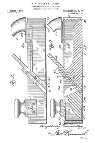
Figure 1 is a side elevational view of a plane embodying the improvements of our invention;
Fig. 2 is a top plan view of the same;
Fig. 3 is a longitudinal sectional view taken on the line 3–3 of Fig. 2 looking in the direction of the arrow;
Fig. 4 is a transverse vertical sectional view taken on the line 4–4 of Fig. 2 looking in the direction of the arrow;
Fig. 5 is a similar view taken on the line 5–5 of Fig. 2 looking in the direction of the arrow;
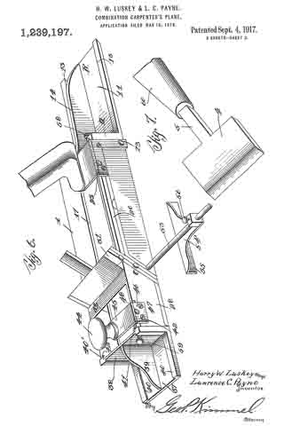
Fig. 6 is a reduced perspective view of our improved plane showing the same in use; and
Fig. 7 is an enlarged perspective view of the cutting element removed and in use as a chisel.
Referring more particularly to the drawings, wherein similar characters of reference designate like and corresponding parts throughout the various views, 1 designates the main body of our improved plane, said body being provided with an inclined front wall 2 having a plate 3 rigidly associated therewith. The cutting member of the plane is shown and is composed of a blade 4 having a shank 5 extending therefrom, said shank 5 lying on the inclined wall 2 beneath the plate 3. A set screw 6 is provided for adjustably maintaining the blade 4 in desired position. its best shown in Fig. 5 the body is provided with a manipulating handle 7 carried on a laterally extending arm 8 provided with a downturned portion 9 secured to the body 1 by means of screws 10 or the like. A rear extension member R is provided, the same having a right-angle wall portion 19, the main portion or sole 11 being provided with dove-tailed flanges 13 engageable with complemental recesses formed on the top portion of the body 1. The strengthening web 14 is cast integral with the main portion and the wall 12. The outer face of the wall 12 is provided with dove-tailed flanges 15 for engagement, at times, with complementally formed recesses on the marginal end edges of the body 1. This is best shown in Fig. 2, one corner of the member 11 being broken away to illustrate one of the dove-tailed recesses which is designated 16. Of course, a slot or recess 17 is provided in the body 1 to accommodate the strengthening web 14.
The one side portion of the body 1 is provided with a recess 19 at the base of which is hingedly mounted an angle-gage 20. The angle-gage is mounted on trunnions 21 and 29. extending from the free end thereof and arranged in complemental openings in the body. A set screw 23 serves to maintain the gage 20 in the angle to which the same has been set, said screw engaging the trunnion 22 as best shown in Fig. 1. A recess 24 is provided in the body 1 adjacent the upper marginal edge of the gage 20 for facilitating engagement of the user’s finger with said gage to remove the same from the recess. A set screw 25 serves to prevent accidental dislodgment of the member 11.
We provide a front section for the plane, said section including a body 28 having a diagonal rear wall 29 having dove-tailed flanges 30 along the marginal edges thereof. The flanges 30 serve to form a sliding engagement with complementally arranged recesses 31 formed along the marginal edges of a plate 32, said plate being in turn engaged with the plate 3 hereinbefore referred to, said plate 32 and plate 3 being detachably engaged, the dove-tailed engagement being indicated at 33. The body 28 is provided with a tapering opening 34, said opening being adapted to aline with registering openings 35 formed in the plates 3 and 32.
A front extension member is provided and is formed with a main body portion or sole 37 and a right-angle wall portion 38, said portions being strengthened by a web 39, the marginal edges of the portion 37 being formed with dove-tailed flanges 40 for engagement with complementally arranged dove-tailed recesses 40’ formed on the body 28. The outer face of the wall 38 is provided with flanges 41 for engagement with recesses 42 formed in the end portion of the body 28, said engagement being best shown in Fig. 6. A suitable recess 43 is provided in the body 38 for accommodating the web 39.
A knob or handle 44 is provided, carried on a bracket 45, having a downturned portion 46 secured to the side of the body 28 by means of screws 47 or the like. A set screw 48 carried in the downturned portion 46 of the bracket 45 serves to engage the member 37 to prevent dislodgment of the same. The base of the body 28 is provided with marginally arranged dove-tailed recesses 49, a plate 50 being receivable on the bottom of said body and being formed with dove-tailed flanges 51 for engagement with said recesses. The flanges 51 are also engageable, at times, with the recesses 42 formed on the end of said body for a purpose which will hereinafter appear.
We provide a gage for use in connection with the plane, said gage including a rod 53 adapted for threaded engagement with an opening 54 provided in the body 1 of the plane, said rod extending laterally therefrom. A slidable gage member 54’ is carried on the rod, said gage member being provided with a flange 55 for engagement with the marginal edge of the work, a set screw 56 being provided for engagement with the rod 53, whereby to lock the gage member at a desired point on said rod.
It will thus be seen that in our improved plane we have provided a device, which owing to the detachable association of the parts provided, is capable of use in connection with various classes of work. The plane may be used as an ordinary plane, and when used in this capacity the parts are associated as shown in Fig. 1. Should it be desired to use the plane as a nose plane the front portion 28 is removed, the plate 32 being permitted to remain in position on the portion 1. This permits the plane to reach otherwise inaccessible points owing to the absence of any extension interfering with the blade 4. Should it be desired to lengthen the plane the extensions 11 and 37 may be applied to the sections 1 and 28, respectiveiy, as shown in Fig. 6. A set screw 58 is provided on the wall 12 of the section 11, said set screw engaging the end of the body 1 and maintaining the extension 11 against vertical movement when applied as shown in Fig. 6. A similar set screw 59 is provided in the wall 38 of the extension 37 for a purpose similar to that of the screw 58.
The function of the gage 54 will be best apparent in using the device as a nose plane as hereinbefore set forth, said gage serving to engage the marginal edge of the work for guiding the plane.
The plane is also adapted for use on curved surfaces, either convex or concave. When using the plane on a convex surface, all of the parts are shown in Fig. 1, with the exception of the extension 37 and the plate 50. The extension 37 is removed entirely and the plate 50 substituted therefor, the lower end of the plate 50 extending below the under surface of the plane body to guide the same when moving over a convex surface.
In using the device for concave work all of the parts are maintained as shown in Fig. 1 with the exception of the relative positions of the bodies 1 and 28, in this instance the body 28 being moved upwardly relative to the body 1 so as to expose the knife blade A for engagement with the concave surface over which the plane is operating.
Referring to Fig. 7 the peculiar construction of the blade at permits of ready removal from the plane, the shank 5 being adapted to engage a suitable handle 60 adapting the blade to use as a chisel. Thus it will be seen that we have provided a plane which is applicable for use in connection with various classes of work, the novel arrangement of the elements permitting a wide range of adjustment. A spirit level 61 is provided in one wall of the body 1 for an obvious purpose.
The plane is also adapted for use on laterally beveled surfaces, the angle-gage 20 being adapted to be set at various angles relative to the plane body for this purpose.
It is thought that the detail construction and arrangement of the parts of our improved plane will be apparent from the foregoing description taken in connection with the accompanying drawings, the simplicity and durability of said structure being one of its greatest advantages over the prior devices of this character. It is, of course, to be understood that the various parts of the device may be cast, suitable milling being employed to cause the dove-tailed grooves and the like to snugly engage.
While we have described our invention and shown the same as embodying a specific structure, it is of course, to be understood that we do not limit ourselves to this structure, but reserve the right to make such changes in the same as do not depart from the spirit and scope of the invention as claimed.
Having thus fully described our invention, what we claim as new and desire to secure by Letters Patent, is :–
1. in a bench plane including a body portion, the forward and rearward ends of the body being provided with dove-tailed flanges, extension members having complementally formed recesses therein to receive said flanges, the extensions being vertically adjustable relative to the body, and the extensions being adapted to be housed upon the body when detached from the ends.
2. In a bench plane including a body portion, the forward and rearward portions of the body being provided with longitudinally extending slots, extension members detachably associated with the forward and rearward portions of the body, webs formed on each extension member adapted to be received in said slots when the extensions are detached from the forward and rearward portions of the body.
3. In a bench plane including a body portion, the forward and rearward portions of the plane being provided with a longitudinally extending slot, an extension member adapted to be detachably associated with the forward and rearward end portions of the plane, a web formed on said extension ment ber, the sole of the extension member being adapted to be retained in alinement with the sole of the plane when used as extensions, the webs adapted to be received in said slots when the extensions are detached from the ends of the plane, the under surface of the extension soles being adapted to engage the upper surface of the plane.
In testimony whereof, we affix our signatures hereto.
HARRY W. LUSKEY.
LAWRENCE C. PAYNE.
Copies of this patent may be obtained for five cents each, by addressing the “Commissioner of Patents, Washington, D. C.”
_________________