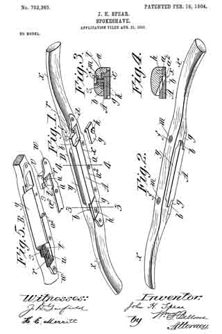
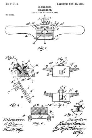
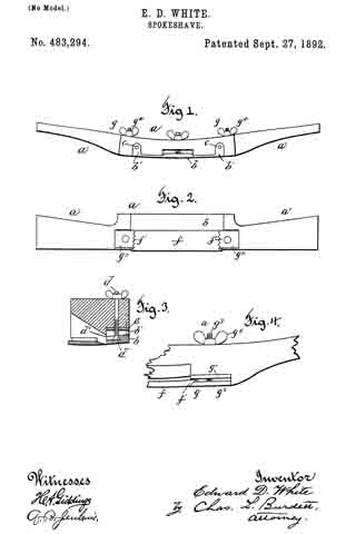
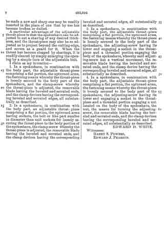
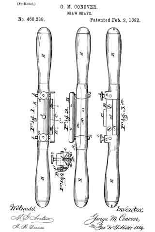
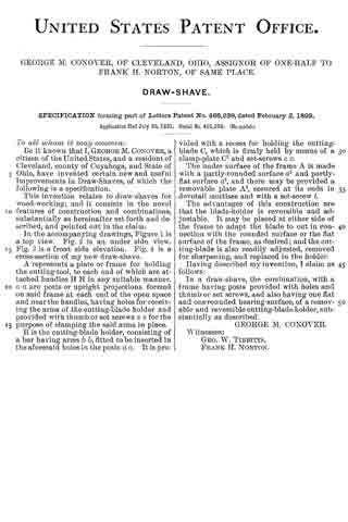
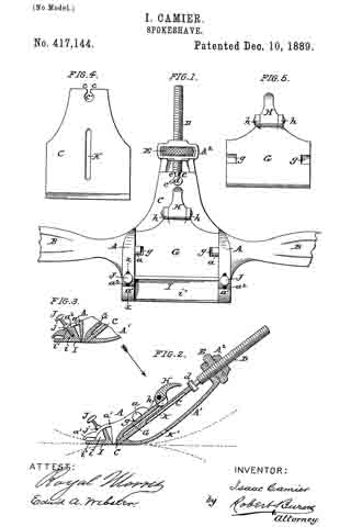
No. 1,332,919 – Spokeshave (Adolph P. Ritter) (1920)

[paiddownloads id=”725″]1332919


UNITED STATES PATENT OFFICE.

_________________

ADOLPH P. RITTER, OF CHICAGO, ILLINOIS.

SPOKESHAVE.

_________________

1,332,919. Specification of Letters Patent. Patented Mar. 9, 1920.
Application filed March 10, 1919. Serial No. 281,666.

_________________

To all whom it may concern:

Be it known that I, ADOLPH P. RITTER, a citizen of the United States, and a resident of the city of Chicago, in the county of Cook and State of Illinois, have invented certain new and useful Improvements in Spokeshaves; and I do hereby declare that the following is a full, clear, and exact description of the same, reference being had to the drawings and to the numerals of reference marked thereon, which form a part of this specification.

This invention relates to an improved type of spokeshave or wood shaving tool, whereon a gage is adjustably mounted and releasably locked in an adjusted position to permit the spoke-shave to be operated to cut a groove of a predetermined width in a piece of wood.

It is an object of this invention to provide a spoke-shave with an adjustable groove gage.

It is also an object of the invention to construct a spoke-shave to permit a gage to be slidably mounted thereon to facilitate the cutting of grooves of uniform width.

Another object of the invention is the construction of a wood shaving tool wherein an adjustable gage mounted on the groove body of the tool is adapted to be held in an adjusted position by means of retaining screws which are positioned to engage in the body grooves.

A further object of this invention is the construction of a spokeshave wherein the margins of the knife slot are provided with scale markings to permit a gage on said spoke-shave to be set in an adjusted position whereby a groove of uniform width can easily be cut by the spoke-shave.

It is furthermore an object of the invention to provide a spoke-shave with an adjustable gage adapted to be set by means of a divided scale so that a groove of uniform width may be conveniently cut in a piece of wood by the spoke-shave blade.

It is an important object of this invention to provide a right and left handed spoke-shave of simple construction adapted to be used with or without an adjustable gage.

Other and further important objects of the invention will be apparent from the disclosures in the drawings and specification.

The invention (in a preferred form) is illustrated in the drawings and hereinafter more fully described.

On the drawings :–

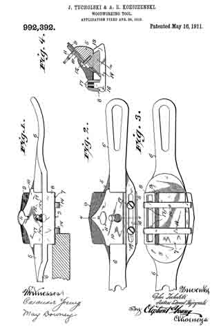
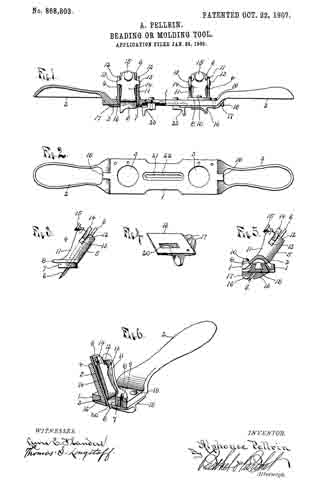
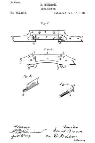
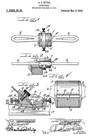
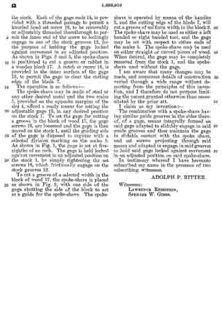
Figure 1 is a bottom plan view of a spoke-shave embodying the principles of this invention.

Fig. 2 is a rear side elevation thereof showing the same set for cutting a groove of a predetermined width in a block of wood.

Fig. 3 is an enlarged detail section taken on line 3–3 of Fig, 2, with parts in elevation.

Fig. 4 is an enlarged bottom plan view of the spoke-shave with the handles broken od and with the gage removed to show the scale markings.

As shown on the drawings :–

The spoke-shave is made of metal and comprises a body portion or stock 1, having handles 2 secured on opposite ends thereof. The handles may be adjustable if preferred. The bottom surface 3, of the stock 1, is smooth and slightly convexed and is provided with a longitudinal slot 4. Each of the longitudinal margns bordering the slot 4, is provided with a divided scale 5, as clearly shown in Fig. 4. Formed in the stock 1, is an inclined surface 6, having a threaded aperture formed therein. Resting upon the inclined surface 6, is a knife or blade 7, provided with an opening 8, and having the cutting edge positioned to project through the slot 4. A retaining plate 9, is removably placed above the blade 7, and is provided with an integral passaged boss or collar 10. To removably hold the blade 7, and the plate 9, in position, a screw bolt 11, is engaged through the passage collar 10, and through the blade opening 8 and is removably threaded into the threaded opening provided for the purpose in the stock 1. The head of the retaining screw bolt 11, is knurled to permit easy operation of said bolt. The slot 8, permits the blade 7, to be adjusted when the bolt 11, is loosened.

Cut or formed in each of the longitudinal sides of the stock 1, is a guide groove 12, which extends the whole length of the stock and is open at both ends. A channel shaped metal gage 13, is provided, having the ends 14 thereof, bent at an angle and provided with integral guide teeth or tapered projections 15, on the inner surfaces thereof to slidably engage in the stock grooves 12, as shown in Fig. 3. The gage is curved complementally with the convex surface 3, of the stock. Each of the gage ends 14, is provided with a threaded passage to permit a knurled head set screw 16, to be removably or adjustably threaded therethrough to permit the inner end of the screw to lockingly engage in one of the stock grooves 12, for the purpose of holding the gage locked against movement in an adjusted position. As shown in Figs. 2 and 3, the spoke-shave is positioned to out a groove or rabbet in a wooden block 17. A notch or recess 18, is provided in the imier surface of the gage 13, to permit the gage to clear the cutting edge of the blade 7.

The operation is as follows :–

The spoke-shave may be made of steel or any other desired metal and the two scales 5, provided on the opposite margins of the slot 4, afford a ready means for setting the adjustable gage 13, in any desired position on the stock 1. To set the gage for cutting a groove in the block of wood 17, the gage screws 16, are loosened and the gage is then moved on the stock 1, until the guiding side of the gage is disposed to register with a selected division marking on the scales 5. As shown in Fig. 1, the gage is set at five-eighths of an inch. The gage is held locked against movement in an adjusted position on the stock 1, by simply tightening the set screws 16, which frictionally engage on the stock grooves 12.

To cut a groove of a selected width in the block of wood 17, the spoke-shave is placed as shown in Fig. 2, with one side of the gage abutting the side of the block to act as a guide for the spoke-shave. The spoke-shave is operated by means of the handles 2, and the cutting edge of the blade 7, will out a groove of uniform width in the block 9. The spoke-shave may be used as either a left handed or right handed tool, and the gage may be set with respect to either ends of the scales 5. The spoke-shave may be used on either straight or curved pieces of wood. When desired, the gage may be completely removed from the stock 1, and the spoke shave used without the gage.

I am aware that many changes may be made, and numerous details of construction varied through a wide range without departing from the principles of this invention, and I therefore do not purpose limiting the patent granted otherwise than necessitated by the prior art.

I claim as my invention :–

The combination with a spoke-shave having similar guide grooves in the sides thereof, of a gage, means integrally formed on said gage adapted to slidably engage in said guide grooves and thus maintain the gage in slidable contact with the spoke shave, and set screws projecting through said means and adapted to engage in said grooves to hold said gage locked against movement in an adjusted position on said spoke-shave.

In testimony whereof I have hereunto subscribed my name in the presence of two subscribing witnesses.

ADOLPH P. RITTER.

Witnesses:
LAWRENCE REIBSTEIN,
SPENCER W. GIBBS.

No. 992,392 – Woodworking-Tool (John Tucholski And Antoni Edmond Koziczenski) (1911)

[paiddownloads id=”679″]992392


UNITED STATES PATENT OFFICE.

_________________

JOHN TUCHOLSKI AND ANTONI EDMOND KOZICZENSKI, OF RACINE, WISCONSIN.

WOODWORKING-TOOL.

_________________

992,392. Specification of Letters Patent. Patented May 16, 1911.
Application filed April 30, 1910. Serial No. 558,576.

_________________

To all whom it may concern:

Be it known that we, JOHN TUCHOLSKI and ANTONI EDMOND KOZICZENSKI, both citizens of the United States, and residents of Racine, in the county of Racine and State of Wisconsin, have invented certain new and useful Improvements in Woodworking-Tools; and we do hereby declare that the following is a full, clear, and exact description thereof.

Our invention consists in what is herein particularly set forth with reference to the accompanying drawings and pointed out in the claim of this specification, its object being to provide simple, economical and efficient tools of the spoke-shave species designed to facilitate smoothing, rabbeting and molding work without injury to operators, as well as to provide for accurate gaging of width of cut in rabbeting and molding operations, whether said tools be drawn or pushed by their operators as the grain of the wood worked upon may require.

Figure 1 of the drawings represents a front elevation of a wood-working tool in accordance with our invention having a wedge clamping screw thereof partly broken away, and in this view the cutting of a rabbet is illustrated; Fig. 2, a plan view of the tool; Fig. 3, a similar view of the same reversed, and Fig. 4, a transverse section of said tool indicated by 4–4 in Fig. 2.

Referring by numerals to the drawings, 5 indicates the central stock, and 6 each of the oppositely extending handles of our improved tool said stock and handles being preferably cast together in one piece. The sole 7 is a central depending extension of the stock, whereby more than ordinary clearance is had under the handles, in order to prevent injury to the hands of an operator and to avoid marring of the work adjacent to a out of said tool, especially when the same is used upon curved work.

A longitudinal slot is provided in the forward portion of the stock through a depending flange 8 of the same, the under extremity of this flange being approximately flush with the sole, and said stock is provided with an angular bit and wedge opening such as is common in planes of various species. The bit 9, wedge 10 and clamp screws 11, 12 for the same herein shown, are also common in the art.

Matching the preferably beveled rear edge of the sole 7, we show hook-ends 13 of gage-bars 14, and each of these bars is provided with a socket-stud 15 that engages the slot 16 of the forward flanged portion of the tool-stock. The contour of each gage-bar stud and the tool-stock slot is such that there is wedging fit of one within the other, and a clamp-screw 17 is employed in engagement with said stud to draw and hold the same in said slot, the gage-bar being adjustable longitudinally of the sole (across which it extends) in proportion to the width of cut desired on the part of the bit in rabbeting or molding operations. By the employment of a pair of gage-bars, as is herein shown, adjusted equi-distant from the sides of the opposing sole, the tool may be drawn or pushed by an operator when cutting rabbets or moldings according as the grain of the wood worked upon is found to run one way or the other, said tool being turned about from time to time to change the cutting direction of its bit.

A straight edge bit being employed, as herein shown, the width of a rabbet may be accurately determined by an adjustment of one or both of the gage-bars 14, and the cutting of the rabbet can be more rapidly and accurately effected than is possible by chiseling. For smooth-work or wide molding, the gage-bars are omitted from the tool and said tool manipulated similar to those of the ordinary spoke-shave species, but to greater advantage because of the clearance afforded for the hands of the operator as above specified.

We claim:

In a woodworking tool of the spoke-shave species, the combination with its central stock having a forward depending and longitudinally slotted flange the under extremity of which is approximately flush with the sole of said stock, a gage-bar that crosses the aforesaid sole and has matching hook engagement with the same at the rear thereof, a socket-stud that extends from the gage-bar and has wedging fit with the slot of the stock-flange, and a clamp-screw engaging the stud.

In testimony that we claim the foregoing we have hereunto set our hands at Racine in the county of Racine and State of Wisconsin in the presence of two witnesses.

JOHN TUCHOLSKI.
ANTONI EDMOND KOZICZENSKI.

Witnesses:
CHRISTIAN JOHNSON,
MICHAEL OKOLEURKI.

_________________

Copies of this patent may be obtained for five cents each, by addressing the “Commissioner of Patents, Washington, D. C.”
_________________

No. 868,803 – Beading Or Molding Tool (Alphonse Pellrin) (1907)

[paiddownloads id=”648″]868803


UNITED STATES PATENT OFFICE.

_________________

ALPHONSE PELLRIN, OF DETROIT, MICHIGAN.

BEADING OR MOLDING TOOL.

_________________

868,803. Specification of Letters Patent. Patented Oct. 22, 1907.
Application filed January 28, 1905. Serial No. 243,162.

_________________

To all whom it may concern:

Be it known that I, ALPHONSE PELLRIN, a citizen of the United States of America, residing at Detroit, in the county of Wayne and State of Michigan, have invented certain new and useful Improvements in Beading or Molding Tools, of which the following is a specification, reference being had therein to the accompanying drawings.

This invention relates to improvements in beading or molding tools, and its object is to provide a simple, cheap and efficient device so constructed that the cutting bit or blade may be rotated or turned to advance one end of the lower or cutting edge ot the bit along the line of its travel to give the same a shearing cut, and also to provide simple means for adjustably holding the bit which may be readily attached or detached.

A further object of the invention is to provide the same with a detachable sole plate and with certain other new and useful features, all as hereinafter more fully described, reference being had to the accompanying drawings, in which

Figure 1, is a front edge elevation of a device embodying the invention and showing the same partly in longitudinal section; Fig. 2, is an inverted plan view ot the stock with all detachable parts removed; Fig. 3, is a side elevation of one of the knife or bit holders, detached; Fig. 4, is a perspective view of one of the sole plates, detached; Fig. 5, is an end view of the device with the handle broken away; and Fig. 6, is an enlarged perspective view of one end of the device showing the same in transverse section through the center of one ol the bit holders.

As shown in the drawing 1 is the stock of the tool consisting of a flat bar which is formed with a handle 2 at each end and with two circular openings 3, one near each end of the flat bar or stock, to receive the bit holders 4, each consisting of a casting formed with an upwardly extending inclined bed 5 for the knife or bit 6, and with a downwardly extending ring-shaped flange 7 to fit the circular opening 3 in the stock. The ring 7 is provided with an outwardly extending circular flange 8 to engage the upper surface of the stock and the holder is adjustably secured in the opening by providing an elongated slot 9 in said flange 8 to receive a screw 10 extending throughout and engaging a screw-threaded opening in the stock. Extending forward from the bed 5 at each side of the bit is the side flange 11, each of which is provided with a notch 12 extending downward from its upper end to receive laterally extending arms 13 on the clamping plate 14 which is provided with a screw-threaded opening near its upper end to receive a clamping thumb screw 15 adapted to extend through said opening and engage the bit, thus rocking said plate on its arms and causing the lower end thereof to press upon the bit and clamp the same firmly to its bed.

The lower end or cutting edge ot the bit 6 is shaped to give the article worked upon the desired form and a sole or wear plate 16 formed on its lower face to conform to the configuration of said cutting edge, is secured to the under surface of the stock over each opening 3 by providing said plate 16 with upwardly extending lugs 17 at one end, forming a dovetail opening between them to receive a dovetail rib 18 on the adjacent end of the stock, beneath the handle, and to further secure each sole plate in place, a screw 19 is provided. An opening 20 in said sole plate is provided for the end of the bit, through which it extends and which is of a size to permit the shavings to pass.

A longitudinal slot 21 is formed in the stock between the openings 3 and the lower face of the stock is cut away adjacent to said slot to term a longitudinal groove 22 to receive the stops 23 adapted to be adjusted along said groove and held therein by screws extending through the slot. These stops are provided to engage the edge of the board or other article being grooved or formed and cause the groove to be formed at the desired distance from the edge thereof.

For convenience the tool is provided with two bits or cutters but it is obvious that only one may be employed and by the particular construction of clamping plate but one screw is necessary and the plate and bit may be quickly removed by simply loosening the thumb screw.

By loosening the screws 10, the holders 4 may be turned within the openings 3 to set the blades or bits at an angle to the longitudinal axis of the stock or bar 1, so that one end of the cutting edge of each will cut in advance of the other end thereof and thus have a shearing action and so that the ends of said cutting edges may be moved nearer or farther from each other, thereby permitting line adjustment of the distance between the outer lines of the cut to be made.

Having thus fully described the invention what I claim is:

1. A routing tool comprising a stock adapted to be moved laterally across the work, a pair of bit holders each secured near one end of the stock, rotatable on an axis vertical to the plane of the stock, and each provided with a bit throat, a bit bed, a bit clamping plate and a bit having a cutting edge whose outer end projects beyond the body of the edge, so disposed that limited relative adjustment of the stock is obtained by the rotation of the bit holders, a guide slot between the bit holders in their axial plane, a gage plate for each bit holder adjustably secured in the slot, and a sole platefor each bit detachably interlocked with the stock outside of each bit holder, extending over and in register with the throat of the holder.

2. A routing tool comprising a narrow, substantially rectangular stock, adapted to be laterally moved across the work, handles on each end of the stock, integral therewith, a pair of bit holders, each consisting of a cylindrical base rotatably secured near one end of the stock vertically to the face of the stock, with its lower face flush with the stock face, means for clamping the holders in any desired angular relation to the stock, comprising a peripheral flange on the base, bearing on the upper side of the stock, a segmental slot in the flange, and a stud screw clamping the flange to the stock, passing through said slot, oblique means for securing a bit in each holder consisting of a bit bed extending obliquely up from the base, marginal, longitudinal flanges on the bed, longitudinally disposed grooves in the upper end portions of the flanges, a bit clamping plate provided with integral, alined lateral lugs between its ends, rocking and sliding in said grooves, and a thumb screw in the upper part of the clamping plate above the lugs, substantially perpendicular to the bed, means for centering the bit holders in relation to a neutral zone, consisting of a longitudinal slot in the stock between the bit holders in axial alinement therewith, whose margins in the stock bed are rabbeted to form a guide, gage plates for the bit holders, each provided with a longitudinal rib engaging the guide, adapted to center the bits in relation to a neutral surface between them, means for shielding bits in the holder comprising soles for each bit holder, each comprising a plate having an opening whose margins register substantially with the working edge of a bit, detachably held in alinement with a bit holder by a rib integrally fortned on the underside of the adjacent handle shank, adapted to dovetail with a lug integral with the plate, and a screw clamping the plate to the stock face over the bit holder.

3. A routing tool comprising a stock having a rectangular plane bed, handles integrally formed at each end thereof, a pair of bit holders in parallel spaced relation, each comprising a cylinder whose axis is perpendicular to the stock bed, each rotatably secured in an aperture in the bed near one end thereof, with their lower end faces flush with the bed, an annular flange on the upper end of each cylinder bearing on the upper side of the stock, a segmental slot in each flange, a screw passing through the slot, secured in the bed, a diametrically disposed throat opening in each cylinder, a lug extending obliquely from each cylinder, whose upper face is longitudinally grooved for a bit bed, a bit clamping plate, tiltably secured over each bed by integral, lateral lugs between the ends of the plate, sliding and rocking in parallel, longitudinal grooves in the side faces of the bed groove, a clamping thumb screw for each plate engaging a screw-threaded aperture in the upper end beyond the lugs, longitudinal, alined, undercut ribs on the under sides of the handle shanks, a shoe for each bit holder, provided with a lug adapted to detachably engage the adjacent undercut rib, and a countersunk screw engaging the stock, a longitudinal, rabbeted slot between the holders in their axial plane, an angle gage plate for each bit holder engaging said rabbeted slot, and a screw clamping each gage plate.

4. A routing tool comprising a stock, draw handles integrally formed at each end thereof, a bit holder rotatably secured at its lower end in the stock, axially perpendicular thereto, whose lower face is flush with the face of the stock, and is diametrically slotted to form a throat, a bit bed extending obliquely upward from the throat, parallel, longitudinal flanges on the sides of the bed integral with the holder, parallel slots in the upper parts of the flanges, a bit clamping plate provided with lateral alined lugs between its ends adapted to slide and rock in said grooves, a thumb-screw in the upper end of the plate transverse to the bed, a sole plate adapted to shield the projecting portion of the bit below the stock, a lug integral with the sole, detachably dovetailed to a rib integral with one of the handle-shanks beyond the end of the bed, a longitudinal guide slot in the bed between the bit holder and the other handle, and an adjustable gage for the bit longitudinally movable in said guide slot.

In testimony whereof I aflix my signature in presence of two witnesses.

ALPHONSE PELLRIN.

Witnesses:
OTTO F. BARTHEL,
THOMAS G. LONGSTAFF.

No. 778,922 – Woodworking-Tool (Justus A. Traut) (1905)

[paiddownloads id=”613″]778922


UNITED STATES PATENT OFFICE.

_________________

JUSTUS A. TRAUT, OF NEW BRITAIN, CONNECTICUT.

WOODWORKING-TOOL.

_________________

SPECIFICATION forming part of Letters Patent No. 778,922, dated January 3, 1905.
Application filed June 6, 1904. Serial No. 211,258.

_________________

To all whom it may concern:

Be it known that I, JUSTUS A. TRAUT, a citizen of the United States, residing in New Britain, in the county of Hartford and State of Connecticut, have invented certain new and useful Improvements in Woodworking-Tools, of which the following is a specification.

This invention relates to woodworking tools or implements of the general class in which cutters are adjustably fixed in place — as, for instance, in spokeshaves and analogous artices.

My present improvement relates to the construction and mounting of the cutter and of the means for attaching the cutter and adjusting the same on the tool or implement.

For the purpose of illustrating my present improvement I have shown the same applied to a spokeshave.

In the drawings accompanying and forming a part of this specification, Figure 1 is a plan view of a spokeshave provided with my present improvements. This view is taken with the cutter uppermost, this arrangement being adopted for convenience of illustration. Fig. 2 is a side elevation as seen from the right hand in Fig. 1. Fig. 3 is a cross-sectional view in line 3 3 of Fig. 1. Fig. 4 is a plan view of the cutter mounted on its carrier. Fig. 5 is a side elevation thereof as seen from the right hand, and Fig. 6 shows an alternative form of the end stops on the blade-carrier.

One of the features of the present improvements relates to the manner in which the cutter is mounted on the implement and by which the strains due to the clamping down of the retaining or binding devices are applied directly to a cutter-carrier, this being accomplished in such a manner as to leave the cutter normally free of such strain or cramping action as would tend to interfere with the proper holding of the same or would tend to spring and deflect the cutter.

My present improvements in the preferred form in which I have illustrated them in the present case are adapted for holding the cutter rigidly in place without applying pressure against the ends of the cutter, and at the same time the clamping of the cutter-carrier is effected by a direct pressure in one direction I only and is accomplished by the clamping action applied to relatively large surfaces, thus producing an efdcient holding of the parts together without producing the deiiection of the cutter or injurious strains in any part of the same. In this connection it will be remembered that the steel of which the cutter edge should be made must be of a high quality, whereas a more ductile and flexible quality of metal is desirable for use in making the carrier or any part of the implement which is subjected to intense strains or pressure. By means of the construction herein illustrated these objects are accomplished, the cutter proper (designated in a general way by 7) being made of relatively hard steel of high quality, while the carrier (designated in a general way by 8) is made of sheet steel or other suitable metal of a relatively tough and flexible character.

Another feature of the improvement relates to the manner of connecting the cutter onto its carrier by uniting the parts together by attaching devices — as, for instance, the rivets 9, located at some distance from the ends 10 of the cutter. In this way I obtain flexibility of the end portions of the carrier, allowing these to spring somewhat, and thus holding the cutter firmly in place without subjecting the cutter-blade itself to the deflecting strain. By this means a slight springing of the implement is prevented from affecting the fastening of the cutter in place, either as to the position of the cutter or the degree of security with which it is held, and by this means also I provide for using a lesser degree of precision in the making of the several parts, as well as for the complete interchangeability of the cutters with a lesser degree of precision in the manufacture of the implement, all of which results and objects are of practical importance and value in this art.

The stock of the tool is designated in a general way by 11 and comprises hand-grips 12 and a body portion 13, to which a sole-carrying member or guard-plate 15 is adjustably secured, the sole 16 whereof may be adjusted relative to the plane of the blade by means of set-screws 17, passing through elongated holes 17′ in the sole-carrying member. It will be seen that the ends 18 of the carrier project beyond the ends 10 of the blade and that they have ways 19 for suitable set-screws 20 for securing the blade to the body of the stock. Blocks 21 may be placed upon the top of the end portions of the carrier and lie between the ends of the blade and shoulders 22 of the stock to add to the finish of the instrument and to assist in the securernent of the carrier. The edge 23 of the blade may be adjusted toward and from the sole to regulate the cut by means of shifting the carrier back and forth and tightening the set-screws after it has been adjusted to the desired position.

It will be seen that the ends of the carrier project beyond the ends of the blade and that the carrier is secured to the blade inwardly of such ends whereby the strain of clamping or of working will be neutralized by the yieldability of the carrier to thereby protect and preserve the blade. The form of blade here employed is one made of a plate of metal having a cutting edge, as 23, along one of its sides, and the carrier is also in the form of a plate of metal overlaying the blade at the side or edge, as 26, opposite the cutting edge.

In using the implement the workman will from time to time grind away the edge 23 of the cutter-blade, the cutter being set forward toward the guard-plate or sole 15. The extending ends 24 of the said carrier are represented in Fig. 4 reaching forward to engage the edge or face 25 of the member 15 to limit the forward adjustment of the cutter, and it is intended that these ends when so constructed shall be ground away from time to time accordingly as the cutter-blade becomes narrower after continued use, so that said ends 24 of the carrier constitute stop devices for enabling the workman to set the cutter in the proper position. For convenience said stop ends are shown formed on the outer sides of the slots 19; but, if desired, they may be formed on the inner side of the said slot, or both sides, as indicated at 24 24′ in Fig. 6.

Having thus described my invention, I claim —

1. A cutting-tool embodying a stock, an unyielding blade, and a yieldable connection between the blade and stock andrrigidly secured to each.

2. In a woodworking-tool, the combination with a stock portion having a sole, of a resilient blade-carrier adjustably secured to the stock adjacent to the sole and intermediate the blade and stock, and a rigid blade having an edge and secured intermediate the ends of said edge to such carrier.

3. A woodworking-tool, comprising a stock portion, a rigid blade having a cutting edge, a relatively yieldable carrier rigidly secured to the blade inward of the ends of said edge and intermediate the blade and stock, and means for adjustably securing said carrier to the stock and engaging the same at points beyond the said ends of the blade edge.

4. A woodworking-tool comprising a stock portion, a rigid blade, a relatively yieldable carrier rigidly secured to the blade inward of its ends, means for adjustably securing said carrier to the stock, and stop-faces on the carrier to limit its forward adjustment.

5. A blade for a woodworking-tool, embodying a rigid plate having a cutting edge upon one side, a resilient carrier secured to the other side and projecting therebeyond and having securing means at such projecting portion.

6. A woodworking-tool having a stock, a guard carried thereby and adjustable relative to the position of the cutter, a cutter rigidly secured inwardly of its ends to a carrier; said carrier; means to secure the carrier to the stock; and stop-faces on the carrier to limit its forward adjustment.

7. In a woodworking-tool the combination with a stock, of a resilient carrier-bar clamped with one face adjacent to the stock, a rigid cutting-blade rigidly secured to the other face of said resilient bar sufficiently remote from its clamped portion to constitute the bar a resilient connection between the blade and the stock, and means to clamp said carrier-bar to the stock.

JUSTUS A. TRAUT.

Witnesses:
W. J. WORAM,
E. G. HOFFMAN.

No. 752,365 – Spokeshave (John H. Spear) (1904)

[paiddownloads id=”599″]752365


UNITED STATES PATENT OFFICE.

_________________

JOHN H. SPEAR, OF SPRINGFIELD, MASSACHUSETTS.

SPOKESHAVE.

_________________

SPECIFICATION forming part of Letters Patent No. 752,365, dated February 16, 1904.
Application filed August 21, 1903. Serial No. 170,298. (No model.)

_________________

To all whom it may concern:

Be it known that I, JOHN H. SPEAR, a citizen of the United States of America, and a resident of Springheld, in the county of Hampden and State of Massachusetts, have invented certain new and useful Improvements in Spoke-shaves, of which the following is a full, clear, and exact description.

This invention relates to improvements in spokeshaves, and more particularly pertains to the means for securing the adjustment convenintly of the blade or knife so that it will cut a fine or thick shaving, as desired, and for confining the knife when adjusted.

The invention consists in a spokeshave constructed substantially as shown in the accompanying drawings and as set forth in the claims.

In the drawings, Figure 1 is a perspective view of the improved spokeshave as seen at its under or shaving side. Fig. 2 is a perspective view of the same as seen looking at the back and top thereof. Fig. 3 is a cross-sectional view as taken on the line 3 3, Fig.1. Fig. 4 is a cross-sectional view as taken on the line 4 4, Fig. 1. Fig. 5 is a perspective view of the under side of the stock or body of the spokeshave, showing also a metallic fitting therefor, a right-hand half of the latter being indicated as broken away and removed from its place of application on, and within, the stock, which is shown recessed for the reception thereof.

Similar characters of reference indicate corresponding parts in all of the views.

Referring to the drawings, A represents the knife or blade, and B the body or stock, having handles x x at its opposite ends, as usual, the said stock being intermediately provided with the usual throat-forming recess y and has a metallic fitting a, adapted to be inset into suitably-formed recesses in the stock therefor and to overlap the under or working-face side thereof and to constitute by its straight-edged portion a2 one boundary of the throat, adjacent which, more or less closely thereto, is the cutting edge x of the blade a. The said fitting a is preferably made as a metallic casting having, as shown in Figs. 1 and 5, ear-lugs w at its ends by which to screw it to the stock, and its inset portion v is formed step-shaped at each end, the one step s at the innermost plane having a tapped perforation t therethrough for the screw f penetrating from the front or upper side of the stock, which has its end in bearing against the inner face of the end lug b of the blade, and the more outwardly-disposed step u has a perforation r, which is screw-tapped, receiving therein the screw h for holding the clamping-plate g against the outer face of the end lug b of the blade.

The parts are originally constructed and relatively arranged so that when the inner face of the end lugs of the blade are practically in contact with the face of the inner step s the cutting edge x of the blade will not be outwardly beyond the under face of the throat-plate.

By loosening the screws h for the clamping-plates g the blade, with its end lugs b b, may of course be crowded bodily transversely and outwardly beyond the plane of the throat-plate, and this is done by inscrewing the screws f f, which penetrate through and beyond the face of the step s of the aforesaid metallic fitting, whereupon the screws h h are set again to confine the clamping-plates to hold the blade-lugs firmly in their adjusted positions as crowded by and in contact on the inner ends of the adjusting-screws f f. The said screws may by having their positions of contact, as indicated in Fig. 3, well toward the inner edges of the blade-lugs b b impart to the blade somewhat of a rocking movement for adjustment, or it may be a bodily-displacing action, the effect being to either swing the blade on a longitudinal axis back from the cutting edge to bring the location of the cutting edge more or less outward for the desired rankness of cut or to displace the blade outwardly without changing the direction of its plane for acquiring practically the same condition for any desired character of shaving.

Inasmuch as the adjusting-screws f f are repeatedly rotated either inwardly or outwardly for varying the rankness of the cut to be taken or made by the knife, and in order that the wood from which the stock of the tool is composed may not be gouged out by the screw-driver, annular cup-shaped and centrally internally perforated bushings m are inset into circular sockets within the upper sides of the stock, it being of course understood, however, that the threaded shanks of the screws f acquire their screw-threaded engagements in and through the portions of the metallic fitting, the inner sides of which constitute the aforesaid innermost steps s s.

This spokeshave may not only be most readily adjusted for any manner of shaving required, but the knife may be bodily transversely adjusted to give any desired width of throat-opening and to correspond with the wearing away at the cutting edge of the knife.

Having thus described my invention, what I claim, and desire to secure by Letters Patent, is —

1. In a spokeshave, the combination with the stock having a throat-recess and having step-formed supports endwise outside thereof, of the knife having end lugs adjacent the innermost steps, the clamping-plates adjacent the outermost steps and overlapping the lugs of the knife, the screws h h for confining the clamping-plates and the adjusting-screws engaging through the aforesaid innermost steps and contacting against the inner faces of the knife-lugs, for the purposes set forth.

2. In a spokeshave, the combination with the stock having the throat-recess and the metallic throat-plate constructed with the stepped portions s and u, let into the body of the stock and having the screw-holes t and r, of the knife a having the end lugs b b the inner faces of which are arranged adjacent the faces of the steps s s, the adjusting-screws f f penetrating said stepped portions s s from the front of the stock and having their inner ends in engagement against the inner faces of the lugs, the clamping-plates g g facewise adjacent the steps u u and overlapping the outer faces of the lugs, and the clamping-screws h h, substantially as described.

3. In a spokeshave, in combination, the stock having the throat-recess and having the inset throat-plate provided with the end portions constructed with the steps s and u, the knife having the end lugs, the adjusting-screws and the bushings m, arranged relatively to the headed portions of said screws in sockets in the top of the stock, the clamping-plates g g and the confining-screws h h therefor, arranged as shown.

Signed by me at Springfield, Massachusetts, in presence of two subscribing witnesses.

JOHN H. SPEAR.

Witnesses:
WM. S. BELLOWS,
A. V. LEAHY.

No. 744,411 – Spokeshave (Huldege Sarasin) (1903)

[paiddownloads id=”592″]744411


UNITED STATES PATENT OFFICE.

_________________

HULDEGE SARASIN, OF AMESBURY, MASSACHUSETTS.

SPOKESHAVE.

_________________

SPECIFICATION forming part of Letters Patent No. 744,411, dated November 17, 1903.
Application filed December 4, 1902. Serial No. 133,829. (No model.)

_________________

To all whom it may concern:

Be it known that l, HULDEGE SARISIN, of Amesbury, county of Essex, State of Massachusetts, have invented an Improvement in Spokeshaves, of which the following description, in connection with the accompanying drawings, is a specification, like characters on the drawings representing like parts.

This invention relates to spokeshaves, and more particularly to spokeshaves which are especially adapted for use in finishing the bodies of carriages.

In the manufacture of carriage-bodies the panels are often rounded at their edges, and in order that this may be readily accomplished I have found it desirable to set the blade of the spokeshave which is used in rounding these edges obliquely with respect to the face of the shave, so that a wedge-shaped shaving will be removed by the blade, thereby enabling the rounding of the panels to be accomplished much more readily than if the blade were set parallel with the face.

The object of my invention is to provide an adjusting means for the blade of a spoke-shave which will enable the blade to be readily adjusted to exactly the desired position with respect to the face of the shave and then to firmly clamp the same while it is held in this position.

For an understanding of the means which I employ to accomplish this object reference is now made to the accompanying drawings, in which —

Figure 1 is a plan view of a spokeshave made according to my invention. Fig. 2 is a cross-section thereof on the line x x of Fig. 1. Fig. 3 is a section on the line y y of Fig. 2. Fig. 4 is a detail view in perspective of the adjusting means for the blade. Fig. 5 is a view similar to Fig. 3 with the blade removed. Fig. 6 is a cross-section on the line z z of Fig. 2. Fig. 7 is a detail view showing the connection between the adjusting screw and slide.

The main body or holder a of the shave is of usual form, having a seat a’, on which a blade b rests, said blade fitted between shoulders at each side of the seat. A clamping-wedge c is adapted to loosely engage grooves a2 in said shoulders, and a clamping-screw d is threaded in said clamping-wedge c and is adapted to engage the upper side of the blade, pressing the under side thereof firmly against the seat a’ and pressing the lower end of the clamping-wedge c against the upper side of the blade. The seat a’, against which the blade is pressed, is provided with a transversely-extending groove a3 in the middle thereof, which extends from the work-face a4 of the holder to the opposite side of said seat.

An adjusting-slide e is fitted to slide in said groove as and is bent at right angles at its upper end and has a slot e’ formed therein. An adjusting-screw i is threaded in the holder in the rear of said slide and is provided with a grooved portion i’, which is fitted in said slot e’ of the slide, so that a swivel connection between said screw and slide is provided. An arm or lever f is pivoted at h to the upper side of said slide and is provided with an angular-shaped projection f’, which is adapted to fit tightly in a correspondingly-shaped aperture in the middle of the blade b, said projection being arranged near the lower end of said lever. The particular shape of this projection is not essential, as any similar form of connection which will prevent the blade from swinging on the lever, yet which will enable the blade to be readily removed, will answer the purpose. A handle f2 extends at an angle to said lever over the head of the adjusting-screw i. The combined thickness of the slide e and lever f is no greater than the depth of the slot a8, the projection f’ being the only part of this adjusting means which extends above the face of the seat a’.

The manner of securing the blade to the holder and of adjusting the same is as follows: The slide e is placed in the groove a3, and the grooved portion of the adjusting-screw i is placed in the slot e’, as shown in Figs. 2 and 7. The blade is then placed on the pivoted arm of lever f, so that the projection f’ thereof fits into the aperture through the blade, and the clamping-wedge c and screw d are placed in position and the screw is tightened, so that they press gently against the blade. Then the screw i is adjusted back and forth until the cutting edge of the blade protrudes the desired distance below the face of the shave, and the lever f is then swung in either direction, swinging the blade, so that its cutting edge is either in an oblique position with respect to the face of the holder, as indicated in dotted lines, Fig. 3, or is exactly parallel therewith, as shown in full lines. The screw d is then tightened, clamping the blade in the position to which it was adjusted. If it is desired to change the adjustment of the blade, it is simply necessary to loosen the screw d and swing the lever f or draw the slide e up or down by means of the screw i until the desired adjustment has been secured.

Having thus described my invention, what I claim as new, and desire to secure by Letters Patent, is —

1. In a spokeshave, a holder having a work-face and a blade-seat, a blade resting on said seat, and means for clamping the same thereon, a slide and means for adjusting the same to and from the work-face, and for holding the same against transverse movement, an adjusting-lever pivoted to said slide, engaging means between said blade and lever for holding the blade from swinging movement with relation to the lever, whereby said lever and blade may be simultaneously swung on the same pivot, substantially as described.

2. In a spokeshave, a holder having a work-face, and a blade-seat, a blade resting on said seat and means for clamping the same thereon, a slide and means for adjusting the same to and from the work-face, and for holding the same against transverse movement, an adjusting-lever pivoted to said slide, a projection rigid with said lever and arranged in a correspondingly-shaped aperture with which said blade is provided, and holding the blade from swinging movement with relation to the lever, whereby said blade and lever may be simultaneously swung on the same pivot, substantially as described.

In testimony whereof I have signed my name to this specification in the presence of two subscribing witnesses.

HULDEGE SARASIN.

Witnesses:
LOUIS H. HARRIMAN,
H. B. DAVIS.

No. 679,702 – Spokeshave (Walter D. Murray) (1901)

[paiddownloads id=”554″]679702


UNITED STATES PATENT OFFICE.

_________________

WALTER D. MURRAY, OF PORTLAND, MAINE, ASSIGNOR,
OF ONE-HALF TO WALTER ACKROYD, OF SAME PLACE.

SPOKESHAVE.

_________________

SPECIFICATION forming part of Letters Patent No. 679,702, dated July 30, 1901.
Application filed May 31, 1900. Serial No. 18,627. (No model.)

_________________

To all whom it may concern:

Be it known that l, WALTER D. MURRAY, a citizen of the United States, residing at Portland, in the county of Cumberland, in the State of Maine, have invented certain new and useful lmprovements in Spokeshaves, of which the following is a specification.

This invention relates to that class of wood-working planes known as spokeshaves.

One object of the invention is to provide a spokeshave with a detachable reversible sole-piece, either edge of which may be used to vary the form of the spokeshave to adapt it for either concave or straight work.

Another object of the invention is to provide simple and effective means for raising and lowering the blade, whereby either end thereof may be moved as desired independently of the other to seen re accuracy of adjustment.

Another object is to provide improved handles for the spokeshave for insuring a better grip and a steadier working tool.

Figure 1 of the accompanying drawings represents a front elevation of this spokeshave. Fig. 2 represents a rear elevation thereof. Fig. 3 represents a central transverse section on line 3 3 of Fig. 1. Fig. 4 represents a similar section with the sole-piece reversed. Fig. 5 represents a perspective view of the detachable sole-piece. Fig. 6 represents a perspective view of the blade or cutter. Fig. 7 represents a rear elevation of the stock, the detachable sole-piece being removed. Fig. 8 represents another form of connection between the blade and the adjusting-screws therefor. Fig. 9 represents an end view of the stock, one of the handles being shown in section on line 9 9 of Fig. 1.

The same reference numbers indicate corresponding parts in all the figures.

In the form of spokeshave illustrated in the accompanying drawings a body or stock 10, having handles 20 and 30 at its opposite ends, is recessed at its back to receive a detachable sole-piece 40. The recessing of the stock forms a rear bed for the blade and shoulders 11 and 12, against which the ends of the sole-piece 40 abut. These shoulders 11 and 12 are provided with screw-threaded sockets 13 and 14, adapted to receive headed screws 50 and 60, respectively, the object of which will be hereinafter described. This stock is provided with a slot 17, through which the shavings pass. Means are provided on the stock and sole-piece for adjusting the latter incorrect position, and these means may consist of lags on one part and notches in the other. When constructed as here shown, the stock 10 is provided at the opposite ends of its recessed bed with lugs 15 and 16, adapted to engage notches 41 and 42, formed in the opposite ends of the sole-piece 40, whereby the proper adjustment of the sole-piece is accomplished.

The detachable sole-piece 40 is preferably constructed with its opposite edges in different forms, being shown as provided with a flat edge 43 and with a rounded edge 44,and either edge may be used to vary the shape of the spokeshave, as desired, by reversing the sole-piece.

Suitable means are provided for fastening the detachable sole-piece to the stock. In the form shown this sole-piece 40 has a screw-threaded shank 45 extending at right angles from the center of its inner face. This shank 45 may consist of a screw passed through the sole-piece or it may form a part of a bolt, the sole-piece 40 constituting the head thereof. This shank or bolt 45 extends through a perforation 18 in the stock 10, and the outer end thereof is engaged by a thumb-nut 46, which firmly clamps the sole-piece to the stock.

A blade 70, having a longitudinal slot 71 therein, is disposed in the recessed portion of the stock; 10, between it and the sole-piece 40. The bolt 43 of the sole-piece passes through the slot 71 before entering the perforation 18 of the stock, and the screwing down of the thumb-nut 46 thereon clamps the knife 70 firmly in position between the stock and the sole-piece. This blade 70 is provided at its opposite ends, near its top, with means for engaging the adjusting-screws 50 and 60, respectively. In the form shown in Figs. 1 and 2 these means consist of notches 72 and 73. In the form shown in Fig. 8 they consist of lateral lugs 74, which engage grooved or double heads 51 and 61 on the adjusting-screws. This blade may be adjusted at any desired height by simply turning the screws in the direction desired, and either end thereof may be independently raised or lowered to secure accuracy of adjustment by raising or lowering the screw connected therewith. Concave recesses 21 and 31, disposed substantially in a vertical plane and at right angles to the sole of the shave, are formed at the ends of the stock and extend through the adjacent portions of the handles 20 and 30, on the rear side of the latter. These recesses serve as finger-rests for the index-fingers when the shave is grasped in the hands and afford a better grip for the operator and a steadier working tool.

Either the means for adjusting the blade, the peculiar form of handles, or the detachable sole-piece may be applied to any adaptable form of spokeshave.

I claim as my invention —

1. A spokeshave having a detachable rear sole-piece serving as a clamp for the blade.

2. A spokeshave having a detachable reversible rear sole-piece.

3. A spokeshave having a reversible rear sole-piece provided with edges of different forms.

4. A spokeshave provided with a reversible rear sole-piece having edges of different forms, one of said edges being flat and the other rounded.

5. A spokeshave comprising a recessed stock, a blade adapted to fit in said recess, a reversible sole-piece also adapted to fit in said recess behind said blade, said stock being provided with means for engaging said sole-piece, and means for securing the blade and sole-piece to the stock.

6. A spokeshave comprising a stock provided with a recess at its back, a reversible sole-piece, adapted to fit in said recess, interlocking means on said stock and sole-piece, a blade disposed between said stock and sole-piece, and means for securing said sole-piece and blade to said stock.

7. A spokeshave comprising a stock provided vvith a recess at its back and lugs at opposite ends of said recess, a reversible sole-piece adapted to fit in said recess and provided with notches adapted to engage said lugs, a blade disposed between said sole-piece and stock, and means for securing said blade and sole-piece to said stock.

8. A spokeshave comprising a recessed stock having a perforation therein, a detachable rear sole-piece having a bolt attached thereto and adapted to extend through said perforation, a thumb-nut adapted to screw on said bolt and fasten the sole-piece in position, and a blade clamped between said sole-piece and stock.

9. In a spokeshave the combination of a stock provided with a blade-bed and with screvv-sockets adjacent to opposite ends of said bed, a blade provided with notches at its opposite ends, means for clamping said blade to said bed, and adjusting-screws disposed in said sockets and provided with heads engaging said lateral notches.

10. A spokeshave comprising, a stock and handles extending from opposite ends thereof, vertical concave recesses being formed at the ends of the stock and adjacent portions of the handles on the rear side of the latter, which recesses serve as rests for the index-fingers when the shave is grasped by the hands.

WALTER D. MURRAY.

Witnesses:
ALICE H. SULIVAN,
JOSEPH E. DANAHER.

No. 668,299 – Spokeshave (Justus A. Traut) (1901)

[paiddownloads id=”551″]668299


UNITED STATES PATENT OFFICE.

_________________

JUSTUS A. TRAUT, OF NEW BRITAIN, CONNECTICUT.

SPOKESHAVE.

_________________

SPECIFICATION forming part of Letters Patent No. 668,299, dated February 19, 1901.
Application filed October 29, 1900. Serial No. 34,012. (No model.)

_________________

To all whom it may concern:

Be it known that I, JUSTUS A. TRAUT, a citizen of the United States, residing in New Britain, in the county of Hartford and State of Connecticut, have invented certain new and useful Improvements in Spokeshaves, of which the following is a specification.

This invention relates to spokeshaves, and has for one object the provision of an improved tool which may be employed on various varieties of wood with good results and one in which the knife and the guard or throat-gage are adjustable in planes at right angles to each other; the back of the guard being formed with a plane face constituting a wall of the throat for the reception of the shavings, whereby the straight edge of said guard opposed to the knife may when injured or blunted be readily renewed by simply grinding said face.

A further object of the invention is the provision within the stock of the spokeshave of a chamber for the reception of shavings, the upper wall of said chamber being curved outwardly to facilitate the discharge of said shavings.

A further object of the invention is the provision, in connection with a spokeshave, of a guard or throat-gage, the working surface of which is convex both transversely and longitudinally.

In the accompanying drawings, Figure 1 is a plan view of my improved spokeshave, part of one of the handles being broken away. Fig. 2 is a side elevation, partially in section. Figs. 3 and 3a are transverse sections on line into of Figs. 1 and 2, showing different adjustments of the guard or throat-gage. Fig. 4 is a perspective view of the knife or cutter. Fig. 5 is a perspective view of the guard, and Fig. 6 is a perspective view of one of the bolts for adjustably securing the knife in position.

Similar characters designate corresponding parts throughout the several views.

Referring to the drawings, the numeral 5 designates the stock of my improved spoke-shave, having the usual handles 5′ 52 and provided with a chamber 6 (the wall 6′ of which is curved outward for a purpose hereinafter described) and with a forward straight portion 62.

Formed in the stock at each end of the chamber 6 are grooves 7, having rabbeted portions 7′, constituting guideways for the reception of flanges 8 on the ends of a knife or cutter 9, which is preferably of the “razor-blade” type and is slightly curved longitudinally, and fitted in said grooves 7 are the flat oblong heads 10′ of bolts 10, the threaded shanks of which pass through perforations in the stock and carry thumb-nuts 12, by turning which the heads 10′ may either be forced tightly against the flanges 8 of the cutter or released therefrom to permit said cutter to be adjusted, as desired. Cooperating with this cutter is a guard or throat-gage 13, slotted at 13′ for the reception of screws 14, which enter the stock, in virtue of which construction the guard may be adjusted transversely of the cutter to vary the dimensions of the throat in which the shavings enter between said parts.
It will be observed by reference to Figs. 3 and 3a that this guard is provided with a plane back 132, which terminates in a straight edge 133, and when this straight edge is blunted or otherwise injured by wear, as frequently happens, it can readily be restored by removing the guard and grinding the flat face 132, after which it can be replaced with said face in engagement with the corresponding flat face 62 of the stock. On its lower or grinding surface the guard is made convex both longitudinally and transversely, as at 15, and can therefore much more readily be applied to rounded surfaces of the work. The face 15, which extends outward from the edge 133, is joined to the back 132 by the curved surface, which at its upper portion becomes nearly or quite parallel to the back, forming a body of convenient thickness in which to locate the slots 13′.

By reference to Figs. 3 and 3a it will be seen that the knife 9 and guard 13 may be so adjusted with relation to each other that the cutting edge of the knife will be brought into line with and almost touch the straight edge of the guard, whereby a very fine shaving may be removed from the work, if desired.
This is especially important when cutting hard wood or across the grain and obviates to a large extent the danger of splitting the wood or of tearing out a splinter therefrom — accidents of frequent occurrence with the old styles of spokeshaves, in which the knife overlaps a beveled edge on the guard.

As is well known, chips or shavings entering the mouth between the guard and knife tend to curl or assume a helical form, and to aid them in this action they are caused to impinge against the curved wall 6’ of the chamber 6 and are by said wall guided and defiected toward the exterior of the stock.

By my improved construction it will be seen that the guard may be so adjusted that the edge of the knife may be brought into line with the straight edge 133 or caused slightly to overlap the same, if desired, thereby enabling the tool to be employed on various kinds of woods, either hard or soft, at pleasure, for, as is obvious, the height of the knife above the guide-surface and also the position of the cutting edge may be regulated with nicety to obtain a throat of the desired width.

As will be observed, the flat oblong heads 10′ of the bolts 10 extend equally on each side of said bolts, and as said heads snugly fill the grooves 7 of the stock the bolts are thus interchangeable and reversible, so that the parts may be disassembled and reassembled regardless of their original positions. Furthermore, the top surfaces of the heads of these bolts and the bearing-surface of the guard or throat-gage are flush with each other, so as to form a smooth working face for the tool.

Preferably the stock and its handles are formed of metal in an integral casting, although the invention is not limited in this respect.

My invention is not limited to the precise details illustrated and described, and modifications may be made in the shape of the parts without departure therefrom.

Having thus described my invention, what I claim is —

1. In a spokeshave, the combination with a chambered stock of a cutter secured in said stock; and a guard or throat-gage cooperating with said cutter and having a working face curved in two directions and a plane back adjacent to the curved surface, said guard being adjustable to bring the working surface of said gage substantially to a position in line with the edge of the cutter.

2. In a spokeshave, the combination, with a stock and its handles, said stock having a chamber with an outwardly-curved wall and also having grooves and guideways at the ends of said chamber, of a longitudinally-curved cutter having flanges fitted in the ways of said stock; bolts having heads in engagement with said flanges; a guard or throat-gage having a straight back portion adjustably secured to the forward wall of the stock, the working surface of said guard or throat-gage projecting from said back portion and being curved both longitudinally and transversely, and said gage being adjustable on the stock to bring its working surface substantially into line with the edge of the cutter, substantially as and for the purpose specified.

JUSTUS A. TRAUT.

Witnesses:
ROBT. N. PECK,
M. G. PORTER.

No. 646,262 – Wood-Plane (Herbert M. Coe) (1900)

[paiddownloads id=”546″]646262


UNITED STATES PATENT OFFICE.

_________________

HERBERT M. COE, OF PHOENIX, ARIZONA TERRITORY.

WOOD-PLANE.

_________________

SPECIFICATION forming part of Letters Patent No. 646,262, dated March 27, 1900.
Application filed May 2, 1899. Serial No. 715,322. (No model.)

_________________

To all whom it may concern:

Be it known that I, HERBERT M. COE, of Phoenix, in the county of Maricopa and Territory of Arizona, have invented a new and Improved Wood-Plane, of which the following is a full, clear, and exact description.

This invention relates to improvements in planes or spoke-shaves adapted for planing or shaving around circular bodies; and the object is to provide a tool of this character of simple yet strong construction that may be quickly adjusted to operate on flat surfaces or on curved surfaces of any radius.

I will describe a wood-plane embodying my invention and then point out the novel features in the appended claim.

Reference is to be had to the accompanying drawings, forming a part of this specification, in which similar characters of reference indicate corresponding parts in all the figures.

Figure 1 is a top plan view of a wood-plane embodying my invention. Fig. 2 is a section on the line 2 2 of Fig. 1, and Fig. 3 is a similar section of a slightly-modified construction.

Referring to the drawings, 1 designates a frame of suitable material — such, for instance, as metal — the side portions of which are curved upward and rearward, and at the front these side portions are connected by a cross-bar 2, and inward of the cross-bar is a cross-block 3. The space between the block 3 and the inner edge or side of the cross-bar 2 forms the throat of the tool. The frame is provided with oppositely-extended handles 4, so that the tool may be used as a spoke-shave. Extended rearward from and underneath the block 3 is a bed-plate 5, which bed-plate extends entirely across the frame or that portion of the frame occupied by the block 3, and it is made of spring material. In Fig. 2 I have shown it secured to the tool by having a portion 6 extended between the upper surface of the block 3 and the cutting-bit 7, which is held in place by the usual plate 8 and screw 9. In Fig. 3, however, I have shown the plate 5 as having its forward edge riveted to the forward end of the block 3.

Pivotally connected to the rear edge of the base-plate 5 is a curved arm 10, which passes through an opening in a lug 11 on the frame 1 and having a clamping-screw 12. In operation the tool may be employed for operating upon flat surfaces, and in such case the bed-plate will be arranged as indicated in full lines in Fig. 2. When it is to be used upon cylindrical or similar curved surfaces, the bed-plate 5 may be deflected to any desired degree to conform it to the shape or size of the article operated upon by moving the arm 10 through the lug 11 and clamping it by the screw 12.

While I have indicated in dotted lines in Fig. 2 a position for the plate 5 when the tool is to be used upon the exterior of a cylindrical body, it is obvious that the plate may be deflected in the opposite direction, so that the tool may be used on the inner side of a cylinder or the like.

Having thus fully described my invention, I claim as new and desire to secure by Letters Patent —

A wood-plane, comprising a frame, a cross-block in said frame upon which the plane-bit is designed to be secured, a flexible bed-plate extended rearward from said cross-block and having at its front end a portion extended upward between the block and bit and secured between the same, a curved arm having pivotal connection with the rear end of the plate, a perforated lug on the frame through which said arm may move, and a clamping-screw in the lug, substantially as specified.

HERBERT M. COE.

Witnesses:
J. C. DAVIS,
C. H. DAVIS.

No. 555,228 – Spokeshave And Rabbet-Plane (Justus A. Traut) (1896)

[paiddownloads id=”524″]555228


UNITED STATES PATENT OFFICE.

_________________

JUSTUS A. TRAUT, OF NEW BRITAIN, CONNECTICUT.

SPOKESHAVE AND RABBET-PLANE.

_________________

SPECIFICATION forming part of Letters Patent No. 555,228, dated February 25, 1896.
Application filed May 31, 1895. Serial No. 551,085. (No model.)

_________________

To all whom it may concern:

Be it known that I, JUSTUS A. TRAUT, a citizen of the United States, residing at New Britain, in the county of Hartford and State of Connecticut, have invented certain new and useful Improvements in Spokeshaves and Rabbet-Planes, of which the following is a specification.

This invention relates to planes, but more particularly to interchangeable spokeshaves and rabbet-planes, and the object of the invention is to provide in one device a tool commonly known as a “spokeshave” adapted to work upon forms of curved or irregular shape, and a plane commonly known as a “rabbet-plane” adapted to shave or plane rabbets in work of irregular or curved shape, and especially for working within a curved rim upon the side of a disk or plate.

A further object of the invention is to provide an improved device in connection with the interchangeable spokeshave and rabbet-plane for regulating or gaging the depth of the cut or shave to be made when the device is used as a rabbet-plane.

A further object of the invention is to also provide an implement or tool, simple and durable in construction, and which will not get out of order in the use thereof, and which is adapted, by means of its particular construction, to work with great accuracy upon many classes of material other than spokes, although the tool is ordinarily termed a “spokeshave.”

In the accompanying drawings, forming a part of this specification, Figure 1 is a view of the interchangeable tool when used as a spokeshave, showing the open side or chamber of the stock and also showing a part thereof in section. Fig. 2 is a view of the device at right angles to the view shown in Fig. 1 and having one of the handles thereof removed. Fig. 3 is a transverse section of the stock in line a a, Fig. 1, looking toward the left-hand end thereof. Fig. 4 is a view of the interchangeable tool when used as a rabbet-plane and showing it in working position on the rim of a piece of work and also showing the gage in adjusted position to regulate the depth of the shave or cut. Fig. 5 is a detached view of the cutting-knife or bit. Fig. 6 is an end view thereof. Fig, 7 is a view of the gaging device detached from the tool. Fig. 8 is an end view thereof; and Fig. 9 is a partly-sectional view taken in line b b, Fig. 3, for more clearly illustrating the recess 13.

Similar characters of reference indicate corresponding parts in the different figures.

In the preferred form thereof herein shown and described the tool or implement consists of a stock, (designated in a general way by 50,) and is preferably made of metal and of approximately cylindrical shape, whereby it is more especially adapted for work on curved or irregular surfaces.

The stock 50 is cut out or recessed to form a suitable chamber 10 and a concaved seat 11, adapted to contain and support the bit hereinafter described. Extending from end to end of the stock is a suitable slot 12, forming the mouth thereof, and which slot communicates with the interior chambered part of the stock, the lower wall of said slot forming an extension of the concaved seat 11. The interior end walls a and b of the stock are likewise recessed or cut out, as at 13, adjacent to the lower portion of the concaved seat and the mouth of the stock (see Fig. 3) to prevent the clogging of the chips between the knife and the stock.

Seated within the chamber of the stock is a bit (designated generally as 15) of any desired shape and construction suitable for the purpose for which it is to be used, and, as shown in the preferred form thereof, the bit consists of a concave-convex plate, having a shank 16 adapted to fit between the interior end walls a and b of the stock, and a blade 17 projecting beyond the sides of said shank (see Fig. 5) and adapted to work in the slotted ends of the walls and in the mouth of the stock, and extends from end to end or slightly beyond the outer end walls of the stock. (See Fig. 2.)

The convex portion 18 of the shank of the bit is seated in the concaved seat of the chamber, and is adjustably clamped therein by means of a suitable clamping or holding concavo-convex plate 19 and locking devices, preferably binding-screws 20, which project through the elongated slots 21 in the bit and extend into the screw-threaded recesses in the concaved wall of the stock. (See Fig. 1.) By tightening or loosening the binding-screws 20, extending through the elongated slots of the bit, the cutting-edge of the bit can be adjusted in the mouth of the stock to any desired position to adapt it for the work to be done. The outer wall of the approximately cylindrical stock adjacent to the mouth thereof is beveled or flattened to form the sole 22 of the stock.

The stock is provided with suitable handles 30 and 31, removably secured to the stock in any suitable way, and, as shown, the end walls of the stock are provided with suitable screw-threaded apertures into which threaded studs 23, attached to the ends of the handles, are adapted to be screwed, so that when it is desired to use the tool as a rabbet-plane or on work that requires only the use of one of the handles the opposite handle to the one to be used can be quickly and easily removed and the device used either as a spoheshave with one handle or as a rabbet-plane. (See Figs. 2 and 4.)

The particular construction of the stock and the bit, as hereinbefore set forth, in which the ends of the bit project to or slightly beyond the outer end walls of the stock, which end walls form plane bearing-faces, adapts the tool to be used as a rabbet-plane on the removal of one of the handles.

In order to regulate the depth of shave or cut of the bit when the tool is used as a rabbet-plane, a suitable gage or gaging device (designated generally as 35) of a construction adapted for the purpose to which it is to be used is provided and adjustably secured to the stock of the plane.

The gaging device, in the preferred form thereof herein shown, comprises two segmental arms 38, adapted to partially encircle the cylindrical stock and the cutting-edge of the bit, and preferably extends beyond the sole of the stock, (see Fig. 2,) each segmental arm 36, together with suitable means for adjustably securing the same to the stock — such, for instance, substantially as hereinafter set forth-constituting an independent gage for use adjacent to each end of the stock. These segmental arms 36 are preferably integrally united at their inner ends to a sliding bar or member 37, adapted to work in a groove or recess 38 in the outer wall of the cylindrical stock, by means of an elongated slot 39, through which a binding-screw 40 projects into a screw-threaded aperture in the stock. This elongated slot 39 may be of any desired length to permit the gage to be adjusted to any desired position on the stock. For instance, the slot may be extended the entire length of the sliding bar 37, if desired, to permit the tool to shave a recess in a piece of work. of a depth practically the length of the stock.

This improved device for regulating the depth of cut or shave, when the tool is used as a rabbet-plane, not only constitutes a gage but also constitutes a means for protecting the corners of the cutter when the device is used as a spokeshave; but it is obvious that, although the tool is ordinarily designated in the art as a “spokeshave,” the spoke class of work forms but a small percentage of the work upon which the tool may be used. Hence, While the gage acts to regulate the depth of cut, as above stated, when the tool, with one of its handles removed, is used as a rabbet-plane, it is also useful and necessary in connection with the device when used for other purposes than as a rabbet-plane. For instance, if desired to use both handles with the tool, and a groove or recess is to be formed in the straight edge of a board or other material, the gage might be set, as indicated at Fig. 4; or when a certain width of shave is necessary the gage can be adjusted to regulate that width, while at the same time using both handles; or when that portion of the cutter between the ends thereof is used on fine work the gaging device can be adjusted to permit one of its arms to run along the side of the board or other material and thereby act as a guide to prevent the slipping off of the tool.

From the above it will be obvious that the tool can be used as a spokeshave, as a rabbet-plane, or as a tool for many other classes of work, and when the tool is used as an ordinary spokeshave for use on spokes the gage is usually set by means of its elongated slot 39 and binding-screw 40 into the position shown in Fig. 2, and, if desired, both handles attached to the stock. When the tool is to be used for other classes of work, where it is preferably desired to use both handles, the gage is adjusted to the desired position to act as a gage or guide in accordance with the work to be done, whether that portion of the cutter adjacent to one of the outer ends or that portion of the cutter intermediate of its ends is to be used. When, however, the tool is to be used as a rabbet-plane to shave or cut a rabbet of a depth — as, for instance, shown in the work in Fig.4 — one or the other of the handles, 30 or 31, of the tool is removed according to the position of the work to be operated upon, the gage set to the position desired, and the tool is then ready for use.

By having the bit seated in the interior of the stock not only a better appearance is presented but a more rigid and firm seat is formed for the bit, and the same can be more evenly adjusted with relation to the work to be operated upon, while the chamber also forms a means for conducting the chips or shavings of the work that get between the knife edge and the mouth of the stock away from the knife edge and thereby prevents clogging thereof.

Having thus described my invention, I claim —

1. A tool of the class specified, consisting of an appronimately-cylindrical stock, whereby it is adapted to work on curved or irregular surfaces, having its end wall forming a plane bearing-face; a bit joined thereto, and having part of its cutting-blade extending to the plane of such face, whereby it is adapted to cut at the end of said stock.

2. A tool of the class specified, consisting of a chambered stock having its end wall forming a plane bearing-face, and having a mouth; a bit secured in said chamber, and having a part of its cutting-blade extending to the plane of such face, whereby it is adapted to out at the end of said stock.

3. A tool of the class specified, consisting of a chambered, approximately-cylindrical stock having its end walls forming plane bearing-faces, and having a mouth; a bit clamped in the chamber of said stock, and having its cutting-edge adjacent to said month, and having a part of its cutting-blade extending to the planes of such faces, whereby it is adapted to cut at the ends of said stock.

4. ln a tool of the class described, the combination with a chambered, approximately-cylindrical stock, the end walls thereof forming plane bearing-faces, and having a mouth extending from end to end of said stock and substantially adjacent to the plane bearing-faces thereof; of a bit adjustably clamped in the chamber of said stock, and having its cutting-blade of substantially the same length as the mouth of said stock.

5. In a tool of the class described, the combination with a chambered, approximately-cylindrical stock, the end walls thereof forming plane bearing-faces, and having a mouth extending from end to end thereof and substantially adjacent to such plane faces; of a bit adjustably clamped in the chamber of said stock, and having its cutting-blade of substantially the same length as the mouth of said stock; and a gage adjustably secured to said stock.

6. A tool of the class specified, consisting of an approximately-cylindrical stock, whereby it is adapted to work on curved or irregular surfaces, and having its end wall forming a plane bearing-face; a bit joined to the stock, and having a part of its cutting-blade extending to the plane of such face, whereby it is adapted to cut at the end of said stock; and a gage joined to said stock.

7. A tool of the class specified, consisting of a stock having both of its end walls forming plane bearing-faces; a bit joined to the stock, and having a part of its cutting-blade adjacent to each end thereof extending to the planes of such faces, whereby it is adapted to cut at either end of said stock.

8. In a tool of the class specified, the combination of an approximately-cylindrical stock, whereby it is adapted for work on curved or irregular surfaces, the end walls thereof forming plane bearing-faces; a bit adjustably clamped to the stock, and having its cutting-blade extending to the planes of such faces, whereby it is adapted to cut the ends of said stock; and handles removably secured to the ends of said stock, whereby the tool can be used as a spokeshave or as a rabbet-plane.

9. In a tool of the class specified, the combination of an approximately-cylindrical stock, whereby it is adapted for work on curved or irregular surfaces, the end walls of said stock forming plane bearing-faces; a bit adjustably clamped to the stock, and having its cutting-blade extending to the planes of such faces, whereby it is adapted to cut at the ends of said stock; a gage adjustably secured to said stock; and handles removably secured to the ends of said stock, whereby the tool can be used as a spokeshave or as a rabbet-plane.

10. In a tool of the class specified, the combination with a chambered, approximately-cylindrical stock, the end walls of which form plane bearing-faces, and having a mouth extending from end to end thereof; of a bit adjustably clamped in the chamber of said stock, and having its cutting-blade extending substantially adjacent to the planes of such faces;
and removable handles provided with screw-threaded studs adapted to enter screw-threaded apertures in the ends of the stock, whereby the tool can be used as a spokeshave or as a rabbet-plane.

11. In a tool of the class specified, the combination with a chambered, approximately-cylindrical stock, the end walls of which form plane bearing-faces, and having a mouth extending from end to end thereof, and also having a longitudinal recess in its exterior face; of a bit adjustably clamped in the chamber of said stock, and having its blade extending substantially adjacent to the planes of such faces; handles removably secured to the ends of said stock, whereby the tool can be used as a spoke-shave or as a rabbet-plane; and a gage adjustably secured to said stock, and adapted to slide in said longitudinal recess, and regulate the depth of the shave of the tool.

12. In a tool of the class specified, the combination with a chambered, approximately-cylindrical stock, the end walls thereof forming plane bearing-faces, and having a mouth extending from end to end thereof; of a bit adjustably clamped in the chamber of said stock, and having its blade extending substantially adjacent to the planes of such faces; handles removably secured to the ends of said stock, whereby the tool can be used as a spokeshave or as a rabbet-plane; and a gaging device consisting of projecting arms and a sliding bar secured thereto, and adjustably secured to and adapted to slide on said stock to regulate the depth of the shave of the tool.

13. ln a tool of the class specified, the combination with a chambered, approximately-cylindrical stock, the end walls thereof forming plane bearing-faces, and having a mouth extending from end to end thereof; of a bit adjustably clamped in the chamber of the stock, and having its blade extending substantially adjacent to the planes of such faces; handles removably secured to the ends of said stock, whereby the tool can be used as a spoke-shave or as a rabbet-plane; and a gaging device comprising segmental arms, and a sliding bar secured thereto having an elongated slot therein; and means for adjustably securing said gaging device by means of its elongated slot to the stock to permit the same to be adjusted to regulate the depth of the shave of the tool.

14. In a tool of the class specified, the combination with a chambered, approximately-cylindrical stock, the end walls of which form plane bearing-faces, and having a concaved seat therein, and a mouth extending from end to end of said stock, and also having a longitudinal recess on its exterior face; of a concavo-convex bit adapted to be adjustably clamped onto the concaved seat in the chamber of said stock, the blade of said bit extending substantially adjacent to the planes of such faces; handles removably secured to the ends of said stock, whereby the tool can be used as a spokeshave or as a rabbet-plane; a sliding bar adapted to slide in said exterior recess of the stock, and having an elongated slot therein; means for adjustably securing said bar in said recess, and segmental arms secured to said bar, and adapted to partially encircle said cylindrical stock, and adapted to regulate the depth of the shave of the tool.

15. In a tool of the class specified, the combination with a chambered, approximately-cylindrical stock, the end walls thereof forming plane bearing-faces, and having a mouth extending from end to end thereof, of a bit adjustably clamped in the chamber of said stock, and having its blade extending substantially adjacent to the planes of such faces; handles removably secured to the ends of said stock, whereby the tool can be used as a spoke-shave or as a rabbet-plane; and means adjustably secured to said stock for regulating the depth of the shave of the tool.

16. In a tool of the class specified, the combination with a chambered, approximately-cylindrical stock, the end walls of which form plane bearing-faces, and having a mouth extending from end to end thereof, and also having a flattened sole adjacent to said mouth; of a bit adjustably clamped in the chamber of said stock, the shank thereof engaging the interior end walls of the stock, and the blade thereof extending substantially adjacent to the planes of such faces, and handles removably secured to the ends of said stock, whereby the tool can be used as a spokeshave or as a rabbet-plane.

17. In a tool of the class specified, the combination of a stock; the end wall thereof forming a plane bearing-face; a bit joined to the stock, and having a part of its cutting-blade extending to the plane of such face, whereby it is adapted to cut at the end of said stock; a gage secured in position to regulate the depth of the cut of the tool; and a handle removably secured to the end of said stock, whereby the tool can be used as a spokeshave or as a rabbet-plane.

18. In a tool of the class specified, the combination of an approximately-cylindrical stock, whereby it is adapted for work on curved or irregular surfaces, the end walls thereof forming plane bearing-faces; a bit clamped to the stock, and having a part of its cutting-blade extending to the planes of such faces, whereby it is adapted to cut at the ends of said stock; and a gage consisting of a segmental arm having a bar secured thereto having an elongated slot; and means for securing said gage by means of its elongated slot to the stock, whereby it can be adjusted relatively to said stock.

19. In a tool of the class described, the combination with a chambered , approximately-cylindrical stock, the end walls thereof forming plane bearing-faces; and having a concaved seat therein and a mouth extending from end to end of said stock, and substantially adjacent to the plane bearing-faces thereof; of a concave-convex bit adjustably clamped in the chamber of said stock and onto said concaved seat, and having its cutting-blade of substantially the same length as the mouth of said stock ; and a clamping device for adjustably clamping said bit onto the concaved seat of the chamber of the stock.

20. In a tool of the class specified, the combination of a stock, the end wall thereof forming a plane bearing-face; a bit joined to the stock, and having a part of its cutting-blade extending to the plane of such face, whereby it is adapted to cut at the end of such stock; and a handle removably secured to the end of said stock, whereby the tool can be used as a spokeshave or as a rabbet-plane.

JUSTUS A. TRAUT.

Witnesses:
H. S. WALTER,
ROBT. N. PECK.

No. 546,321 – Spokeshave (Albert Gumz) (1895)

[paiddownloads id=”517″]546321


UNITED STATES PATENT OFFICE.

_________________

ALBERT GUMZ, OF MILWAUKEE, WISCONSIN.

SPOKESHAVE.

_________________

SPECIFICATION forming part of Letters Patent No. 546,321, dated September 17, 1895.
Application filed January 20, 1894. Serial No. 497,499. (No model.)

_________________

To all whom it may concern:

Be it known that l, ALBERT GUMZ, a citizen of the United States, and a resident of Milwaukee, in the county of Milwaukee, and in the State of Wisconsin, have invented certain new and useful Improvements in Spokeshaves; and I do hereby declare that the following is a full, clear, and exact description thereof.

My invention relates to spokeshaves; and it consists in certain peculiarities of construction and combination of parts, as will be fully set forth hereinafter and subsequently claimed.

In the drawings, Figure 1 is a top view of the device partly in section. Fig. 2 is a front view of part of the same, partly broken away, and with the set-screw in section, on the line 2 2 of Fig. 4. Fig. 3 is a view with the parts in the same relative positions as in the preceding figure, but looking from the other side, with portions removed, on the line 3 3 of Fig. 4. Fig. 4 is a transverse sectional view on the line 4 4; of Fig. 2.

A A represent the handles of the device, and B the back-plate, C C the sides, and D the front bar of the frame or housing, all of these parts being preferably cast solidly together in one piece, leaving the usual slot or opening a for the passage of the cutting-blade E therethrough. On its under side this blade is provided with series of transverse grooves e e for engagement with pins or projections f f on the free ends of the short arms of the bell-crank levers F F, pivoted, as shown at b b, to the said back-plate B of the frame or housing. The long arms of these levers project beyond the top edge of said plate and terminate in thumb-pieces d d. The back-plate B is provided with a raised portion h to serve as a stop to limit the inward movement of the long arms of said levers F.

G is a retaining-plate adapted to rest on the upper side of the blade E, and provided at each side with projections or pins g g for engagement vvith grooves c c in the sides C C of the housing or frame.

H is a set-screw passing through a screw-threaded hole in the retaining-plate G, and bearing against the blade E when the latter has been adjusted.

The operation of my device will be readily understood from the foregoing description of its construction taken in connection with the accompanying drawings. The long arms of the levers F F are drawn inward against the stop h, and the blade E laid thereon with the pins f f in engagement with the grooves c c in said blade. The retaining-plate G is then placed upon the blade with the pins g g of said plate within the grooves c c in the side of the housing, and before the set-screw H is tightened the levers F F are moved out or in, so that the edge of said plate is advanced or retracted with relation to the opening on the required distance, and then the said set-screw H is tightened and the device ready for operation. By my device the blade may be adjusted evenly by simultaneous and equal movement of both levers; or, if preferred, either end of said blade may be advanced or retracted to a greater extent than the other end by simply operating the corresponding lever, and this can be done at any time by simply loosening the set-screw and operating the lever or levers without taking out the blade or detaching the parts, and hence a great saving of time is effected and the utmost nicety of adjustment insured.

From the foregoing it will be seen that the described bell-crank levers perform the double function of advancing and retracting the blade by a simultaneous movement of both and adjusting the edge of said blade to cut evenly by a slight independent movement of said beli-crank levers.

Having new fully described my invention, what I claim as new, and desire to secure by Letters Patent, is —

A spokeshave comprising a suitable handled housing, a blade, and a pair of pivoted bell-crank levers in engagement with said blade for advancing and retracting said blade by a simultaneous movement of both of said levers, and for adjusting the edge of said blade to cut evenly by a slight independent movement of the levers, substantially as set forth.

In testimony that I claim the foregoing I have hereunto set my hand, at Milwaukee, in the county of Milwaukee and State of Wisconsin, in the presence of two witnesses.

ALBERT GUMZ.

Witnesses:
H. G. UNDERWOOD,
HENRY DANKERT.

No. 508,427 – Spokeshave (Herbert D. Lanfair) (1893)

[paiddownloads id=”496″]508427


UNITED STATES PATENT OFFICE.

_________________

HERBERT D. LANFAIR, OF ERVING, ASSIGNOR TO THE
MILLER’S FALLS COMPANY, OF MILLER’S FALLS, MASSACHUSETTS.

SPOKESHAVE.

_________________

SPECIFICATION forming part of Letters Patent No. 508,427, dated November 14, 1893.
Application filed July 3, 1893. Serial No. 479,446. (No model.)

_________________

To all whom it may concern:

Be it known that I, HERBERT D. LANFAIR, of Erving, in the county of Franklin and State of Massachusetts, have invented a certain new and useful Improvement in Spokeshaves, of which the following, taken in connection with the accompanying drawings, is a specification.

My invention relates to spoke shaves, used by hand, upon a great variety of work.

In the drawings like letters of reference indicate corresponding parts.

The particular part of the spoke shave to which my present invention relates is the shoe, so called, and is the bearing surface upon which the face part of the shave rests while in operation.

In the drawings, Figure 1 represents a plan view of a spoke shave, the face or shoe side shown upward. Fig. 2 represents asectional view on line x–x of Fig. 1. Fig. 3, represents the shoe detached from the body.

A is the body of the shave; C, the handles, at either one or both ends of body A.

B is the shoe.

The body A. is preferably formed of metal in the usual manner. The blade or cutter D, is secured to the body A, by screws d or other well known means. The body, A, at points indicated by letter g, is slotted, so that the ends of shoe B, made with a tenon, at either end, indicated by b, will fit the slots, and the shoe will be held in place in the slots by set screws a a. The inner edge of the shoe B next the cutter or blade, of course is placed nearly to the edge of the blade, the opening being varied to suit the work, and the shavings or chips will pass up through this opening and be discharged in the usual manner.

The shoe B. is formed removable and it being formed alike at both ends b, b, is also reversible. The shoe B, being so made adjustable and also removable and the ends formed alike and consequently reversible, end for end, the shoe is further provided with four faces, indicated by c. c’. c2. and c3. New by reversing the shoe B. and also by simply turning it over, we will have formed four distinct bearings or surfaces for the shave, and of course, adapted to different styles of work.

Now, by referring to Fig. 3, the faces c. c’. c2. and c3. will be seen to be flat, oval, beveled and rounding, and they may be varied to best suit all ordinary work to which this class of tool is adapted.

If expedient several shoes may be provided to each shave and by this means a great variety of form of faces may be easily provided. One slice similar tothe one illustrated in Fig. 3. will cover all ordinary work. The shoe B. being adjustable in the slots at g, g, as described and the shoe being held at any point by set screws a. a. acting upon the tenons b. b. the width of the opening can be adjusted to a nicety; for instance, if the work is very hard and of fine grain, the opening can be made very small, or it can be made very large, and it also allows the use of cutters or blades of different thicknesses with equal facility and adjustment as to opening.

The principal point of novelty aside from that already named is the reversibility both as to side and ends, whereby the shoe provides four different and distinct forms of faces or surfaces.

I do not confine myself to the precise form of faces shown in Fig. 3, as the shoe may be made with concave, convex, flat, oval, round, or irregular surfaces or bearings and the removable shoe can be thus adapted to any A style or kind of work.

Having now described my invention, what I claim, and desire to secure by Letters Patent of the United States, is —

In a spoke shave, the shoe B. provided with the tenons b. b. and two or more faces and adapted to be removably and reversibly secured to the shave body by suitable means, I substantially as and for the purpose set forth.

In witness whereof I have subscribed my name to this specification, in the presence of two subscribing witnesses, on this 17th day of June, A. D. 1893.

HERBERT D. LANFAIR.

Witnesses:
GEO. E. ROGERS,
H. E. GOODELL.

No. 483,294 – Spokeshave (Edward D. White) (1892)

[paiddownloads id=”487″]483294


UNITED STATES PATENT OFFICE.

_________________

EDWARD D. WHITE, OF HARTFORD, CONNECTICUT.

SPOKESHAVE.

_________________

SPECIFICATION forming part of Letters Patent No. 483,294, dated September 27, 1892.
Application filed January 22, 1892. Serial No. 418,975. (No model.)

_________________

To all whom it may concern:

Be it known that I, EDWARD D. WHITE, of Hartford, in the county of Hartford and State of Connecticut, have invented certain new and useful Improvements in Spokeshaves, of which the following is a full, clear, and exact description, whereby any one skilled in the art can make and use the same.

The special object of my invention is to provide a tool belonging to the class of spoke-shaves that shall be particularly adapted to cutting leather, although it is equally adapted for other uses; and to this end it consists of the details of the several parts making up the spokeshave as a whole and in their combination, as more particularly hereinafter described, and pointed out in the claims.

Referring to the drawings, Figure 1 is a detail front view of a spolreshave embodying my invention. Fig. 2 is a detail view of the under side of the spokeshave. Fig. 3 is a detail view, in cross-section, through the spokeshave, illustrating the method of supporting and adjusting the throat-piece. Fig. 4 is a detail rear view of a portion of a spokeshave embodying my invention.

In the accompanying drawings, the letter a denotes the body part of the spokeshave, made usually of wood and provided at the opposite ends with handles a’, by means of which the tool is held in working.

The letter b denotes a throat-piece located on the under side of the body part of the shave and connected to it by means of screws c, that pass through the upturned arms b’ at opposite ends of the throat-piece. These arms are preferably located in sockets formed in the body part of the shave and are secured by means of these screws or bolts, that pass through holes in the upper ends of the arms, the hole being slightly larger in diameter than the supporting bolt or screw in order to allow the throat-piece to have a swinging movement on such supports. In order to provide for this adjusting movement of the throat-piece, the edge of which extends lengthwise of the blade and immediately in front thereof, the head d’ of a bolt d engages a socket d2, formed in the upper part of the throat-piece, the bolt having a threaded portion extending through the nut e, that is secured to the body part of this spokeshave. The upper end of this bolt is provided with a thumb-nut or suitable handle, by means of which the bolt may be rotated in such manner as to change the position of the front edge of the throat-piece, so as to regulate the width of the opening between the cutting-edge of the blade and the edge of the throat-piece. The blade f is removable and adjustable, and it is secured to the body part of the spokeshave by means of clamp devices, that are located at the opposite ends of the blade. These clamp devices g comprise a bed-piece g’, against which the back part of the blade rests, and which may be formed by the surface of the spokeshave when such part is of metal, but when of wood are preferably formed by pieces of metal located in a suitable socket, and a holding part g2, that is connected by means of a bolt g3 with a nut g4, that fits on the threaded upper end of the bolt that extends through the body of the shave. The ends f’ of the blade proper are beveled and are made irregular, preferably by serrating such edges or forming a number of teeth that are engaged by corresponding teeth formed in the beveled edge of the clamp-plate. These serrations or indentations have a double function, taken in connection with the bevel of the edge: first, to provide for the adjustment of the blade in the direction of the throat-piece, and, next, to enable the blade to be removed and renewed after grinding or replaced by a new blade. The indentations or serrations are made sufficiently close together to permit of any needed degree of forward adjustment of the blade to compensate for the wear of the cutting-edge.

The cutting-blade in my improved spoke-shave is both renewable and adjustable and is clamped by positive clamping means formed to prevent the blade from slipping when the spokeshave is in use, and the blade being of a single piece, without any projecting parts at right angles to the blade, which are needed in old forms of spokeshave, may be ground on any grindstone without regard to its width, and such a blade is therefore readily sharpened. Two or more blades may be provided, so that in case the spokeshave is being used at a distance from a shop where such repairs may be made a new and sharp one may be readily inserted in the place of one that by use has become broken or dulled.

A particular advantage of the adjustable throat-piece is that the spokeshave can be adjusted to out a shaving of any desired thickness, and the throat-piece may also be so adjusted as to project beyond the cutting-edge, and serves as a guard for it. When the throat has become clogged by shavings, it is readily cleared by simply enlarging the opening by a simple turn of the adjustable bolt.

I claim as my invention —

1. In a spokeshave, in combination with the body part, the adjustable throat-piece comprising a flat portion, the upturned arms, the fastening means whereby the throat-piece is loosely secured to the body part of the spokeshave, and the clamp-screw whereby the throat-piece is adjusted, the removable blade having the beveled and serrated ends, and the clamp devices having the corresponding beveled and serrated edges, all substantially as described.

2. In a spokeshave, in combination with the body part, an adjustable throat-piece comprising a flat portion, the upturned arms having sockets, the bolt or like part smaller in diameter than said sockets for loosely securing the throat-piece to the body portion of the spokeshave, the clamp-screw whereby the throat-piece is adjusted, the removable blade having the beveled and serrated ends, and the clamp devices having the corresponding beveled and serrated edges, all substantially as described.

3. In a spokeshave, in combination with the body part, the adjustable throat-piece comprising a flat portion, the upturned arms, the fastening means whereby the throat-piece is loosely secured to the body part of the spokeshave, the adjusting-screw having its lower end engaging a socket in the throat-piece and a threaded portion engaging the body of the spokeshave, whereby said adjusting-screw has a vertical movement, the removable blade having the beveled and serrated ends, and the clamp device having the corresponding beveled and serrated edges, all substantially as described.

4. In a spokeshave, in combination with the body part, the adjustable throat-piece comprising a flat portion, the upturned arms, the fastening means whereby the throat-piece is loosely secured to the body part of the spokeshave, the adjusting-screw having its lower end engaging a socket in the throat-piece and a threaded portion engaging a nut located on the body of the spokeshave, the nut, the means for turning the adjusting-screw, the removable blade having the beveled and serrated ends, and the clamp devices having the corresponding beveled and serrated edges, all substantially as described.

EDWARD D. WHITE.

Witnesses:
HARRY S. POWERS,
EDWARD J. PEARSON.

No. 468,239 – Draw-Shave (George M. Conover) (1892)

[paiddownloads id=”482″]468239


UNITED STATES PATENT OFFICE.

_________________

GEORGE M. CONOVER, OF CLEVELAND, OHIO, ASSIGNOR
OF ONE-HALF TO FRANK H. NORTON, OF SAME PLACE.

DRAW-SHAVE.

_________________

SPECIFICATION forming part of Letters Patent No. 468,239, dated February 2, 1892.
Application filed July 30, 1891. Serial No. 401,229. (No model.)

_________________

To all whom it may concern:

Be it known that I, GEORGE, M. CONOVER, a citizen of the United States, and a resident of Cleveland, county of Cuyahoga, and State of Ohio, have invented certain new and useful Improvements in Draw-Shaves, of which the following is a specification.

This invention relates to draw-shaves for wood-working, and it consists in the novel features of construction and combinations, substantially as hereinafter set forth and described, and pointed out in the claim.

In the accompanying dravvings, Figure 1 is a top view. Fig. 2 is an under side view. Fig. 3 is a front side elevation. Fig. 4 is a cross-section of my new draw-shave.

A represents a plate or frame for holding the cutting-tool, to each end of which are attached handles H H in any suitable manner. a a are posts or upright projections formed on said frame at each end of the open space and near the handles, having holes for receiving the arms of the cutting-blade holder and provided with thumb or set screws s s for the purpose of clamping the said arms in place.

B is the cutting-blade holder, consisting of a bar having arms b b, fitted to be inserted in the aforesaid holes in the posts a a. It is provided with a recess for holding the cutting-blade C, which is firmly held by means of a clamp-plate C2 and set-screws c c.

The under surface of the frame A is made with a partly-rounded surface a2 and partly-flat surface a3, and there may be provided a removable plate A2, secured at its ends in dovetail mortises and with a set-screw t.

The advantages of this construction are that the blade-holder is reversible and adjustable. It may be placed at either side of the frame to adapt the blade to cut in connection with the rounded surface or the flat surface of the frame, as desired; and the cutting-blade is also readily adjusted, removed for sharpening, and replaced in the holder.

Having described my invention, I claim as follows:

In a draw-shave, the combination, with a frame having posts provided with holes and thumb or set screws, and also having one fiat and one rounded bearing-surface, of a removable and reversible cutting-blade holder, substantially as described.

GEORGE M. CONOVER.

Witnesses:
GEO. W. TIBBITTS,
FRANK H. NORTON.

No. 452,498 – Spokeshave (John F. Magnuson) (1891)

[paiddownloads id=”473″]452498


UNITED STATES PATENT OFFICE.

_________________

JOHN F. MAGNUSON, OF NEW YORK, N. Y.

SPOKESHAVE.

_________________

SPECIFICATION forming part of Letters Patent No. 452,498, dated May 19, 1891.
Application filed May 29, 1890. Serial No. 353,530. (No model.)

_________________

To all whom it may concern:

Be it known that I, JOHN F. MAGNUSON, a citizen of Sweden and a resident of New York city, in the county and State of New York, have invented new and useful Improvements in Spokeshaves, of which the following is a specification.

My invention consists, essentially, in a novel contrivance of adjustable-handles adapted for holding the tool in different positions for facilitating the use of it in various different parts and shapes of the work, and it also consists in an improved construction for enabling the tool to be utilized as a corner plane and for the application and adjusting of the guard-cap of the plane bit, all as hereinafter fully described, reference being made to the accompanying drawings, in which —

Figure 1 is a plan view of the tool with the handles adjusted about as in the ordinary spokeshave. Fig. 2 is an inside elevation of the front part of the stock detached and reversed and with the guard-cap attached to it. Fig. 3 is an elevation of the back of the plane bit. Fig. 4 is a transverse section of the complete tool on the line x x of Fig. 1. Fig. 5 is a plan view of the tool with the handles adjusted as for a corner plane. Fig. 6 is a plan view of the tool with the handles as in Fig. 5 and inverted and with one of the handles detached to show the mode of its connection and adjustment. Fig. 7 is a side elevation of the tool with the handles adjusted as in Fig. 5. Fig. 8 is a front elevation of the back part of the stock with one of the handles detached and with the other handle in the normal position of the spokeshave-handle. Fig. 9 is a transverse section of the stock on line w w, Figs. 6, 7, and 8, and Fig. 10 is a section of the front part of the stock on line y y, Figs. 4 and 5.

I construct the stock in two parts a and b, the former being what l call the “back” and the latter the “front” part. The back has the bevel base c, the front face d, the inclined sides e, and the ear-lugs f. The base c that part which slides on the wood, the plane bit q rests on the front face d, the inclined sides e have the handles t pivoted to them, respectively, and the front part b is secured in the ear-lugs f by pivot-studs i entering its shoulders j. Said front part also has a bevel base k to slide on the wood in advance of the plane-bit, above which is a large opening l for the escape of the shavings, and above the opening, but a little below the pivots i, the guard-cap m is attached to the under or rear side by the clamp-screws n slots of the cap, so that the cap can be adjusted up or down to gage it with relation to the edge of the plane-bit, said cap bearing all across the bit slightly above said edge. The front part b has an upward extension p above the pivots i, through which the clamp-screw o is fitted to bear the plane-bit g on the face d, and at the same time bear the lower edge of the guard-cap in on the lower end of the plane-bit just above the edge of said bit by the leverage taking effect thereon through the pivots of said front part.

The outer surfaces of the bevel sides e of the back have pivot-holes s for the handles t and are faced on the margins q, surrounding said holes, and the handles are correspondingly faced at u to seat thereon and have a pivot-stud w in the center of the face u, adapted to fit the hole q and being tapped in its center to receive the fastening-screw x from the upper surface of side e and having a washer y under its head. The face q is recessed at z about a quarter of the circumference of the pivot-hole to provide two stop-shoulders a’ and b’, and the pivot-stud w has a stop-lug c’, which swings between said shoulders and comes to rest on them, respectively, to stop the handle in its different positions. When the handles are in the positions represented in Figs. 4, 5, and 6, said stop-lugs bear against shoulders a’, and when in the positions of Figs.1 and 8 they bear on the shoulders b’. The pivot-screws x and washers y are to be adjusted so as to bind the handle-pivots with sufficient friction to cause them to retain their places when set, but allow them to be shifted without difficulty.

In Figs. 4 and 7 it will be seen that the handles have an upward rise from the pivots to a sufficient height to enable the hand of the user to clear the work while holding the tool, and these are bent at d’ and project for the rest of their length about parallel with the base c k of the tool, which bends give the forward pitch of the handles, so that they range about in line with the cutting-edge of the bit when adjusted as in Figs. 1 and 8, substantially the same as in the ordinary spokeshave. Another feature of this form of the handles and the inclined sides e, to which they are pivoted, is that when shifted to the positions of Figs. 1 and 8 the handles, which are preferably about twice as wide as they are thick, assume the flatwise positions as therein shown, in which they are used separately, one in each hand, and in the positions of Figs. 5 and 6 they turn up edge-wise, side by side, and within narrower space than the width of the stock, suitably for both being grasped by one hand, in which positions the tool can be used substantially as a corner plane for both right and left hand corners, for which purpose it will be seen that the plane-bit is made as wide as the stock and is at its edges flush with the edge of the stock — a condition that is made feasible by the contrivance of the pivoted front part of the stock for clamping the bit and by making the upper part of the plane-bit narrower, as at e’, to extend upward between the ear-lugs by which the front b is pivoted, said ear-lugs being necessarily located within the width of the base c k and of the cutting-edge of the bit to permit the use of the tool in corners. It will be seen that besides this advantage the separate construction and pivoted connection of the front and back parts of the stock enables the handles to be secured by the screws inserted from the inside of the back and the guard-cap to be attached by the screws n inserted from the inside of the front in such manner that the screws have no objectional exterior projections that might interfere with or obstruct in the application of the tool to some shapes of work.

In Figs. 4 and 10 it will be seen that the lower edges of the sides of the front b are beveled downward to the edges b’, so as to make the mouth or lower side of the opening l, for the escape of the shavings as wide as the plane-bit and the whole width of the stock, so that the shavings will enter without obstruction, and so as to be forced upward between the said sides, which are of necessity convergent upward to enable the requisite quantity of material for supporting the lower part of front b to be contained in said sides.

I claim —

1. The combination of the separately-constructed back and front parts of the stock, pivoted together and provided with the clamp-screw, said back having the face for the reception of the plane-bit, and the front having the guard-cap attached to the inner side suitably for being pressed at the lower end on the plane-bit by the clamp-screw, said cap bearing all across the bit, substantially as described.

2. The combination of the separately-constructed back and front parts of the stock, pivoted together and provided with the clamp-screw, said back having the face for the reception of the plane-bit, and the front having the guard-cap, said guard-cap and plane bit having equal width and extending flush with the sides of the stock, and the plane bit having the narrower upper part extending between the ear-lugs of the pivot-joint of the two parts of the stock, substantially as described.

3. The combination, with the stock having the inclined sides, of handles pivoted to said sides, respectively, and adapted to be set in the laterally-projecting positions of spokeshave-handles and also in the rearwardly-projecting position side by side, substantially as described.

4. The combination, with the stock having the inclined sides, of the handles pivoted to said sides, respectively, and adapted to be set in the laterally-projecting positions of spokeshave-handles and also in the rearwardly-projecting position side by side and provided with stops limiting the movements to said positions, substantially as described.

5. The combination, with the stock having the inclined sides, of the handles pivoted to said sides by pivot-studs and the handles entering the pivot-holes of the sides and secured from the inside of the stock by the screws, substantially as described.

6. The combination of the separately-constructed front and back parts of the stock, detachably pivoted together and the handles pivoted to the inclined sides of the stock and secured by the screws and washers inside of the back and under the front part of the stock.

7. The combination, with the stock having the inclined sides, of the handles pivoted thereto and having the curved or angular section d’, substantially as described.

8. A spokeshave-stock made in two separate parts pivoted together and having the space for the plane-bit extending the whole width of the stock, and the front part having the opening for the escape of the shavings made the full width of said stock at the lower sides and with upwardly-converging sides, substantially as described.

9. The combination of the separately-constructed back and front parts of the stock, pivoted together and provided with the clamp-screw, and the guard-cap adjustably attached to the inner side of the front part by the slots and fastening-screws, said back part having the face for reception of the plane-bit, substantially as described.

In testimony that I claim the foregoing as my invention I have signed my name, in presence of two witnesses, this 24th day of April, 1890.

JOHN F. MAGNUSON.

Witnesses:
W. J. MORGAN,
W. B. EWELL.

No. 417,144 – Spokeshave (Isaac Camier) (1889)

[paiddownloads id=”457″]417144


UNITED STATES PATENT OFFICE.

_________________

ISAAC CAMIER, OF CHICAGO, ILLINOIS.

SPOKESHAVE.

_________________

SPECIFICATION forming part of Letters Patent No. 417,144, dated December 10, 1889.
Application filed March 23, 1889. Serial No. 304,516. (No model.)

_________________

To all whom it may concern:

Be it known that I, ISAAC CAMIER, a citizen of the United States, residing at Chicago, in the county of Cook and State of Illinois, have invented certain new and useful Improvements in Spokeshaves; and I do hereby declare the following to be a full, clear, and exact description of the invention, such as will enable others skilled in the art to which it appertains to make and use the same.

This invention relates to certain improvements in the type of spokeshaves shown and described in Letters Patent No. 395,738, issued me January 8, 1889; and the present improvements have for their objects, first, to provide an improved construction which, while furnishing ample and effective means for clamping and holding the cutter-bit, will admit of the use of almost the whole of the same to accommodate for wear due to constant resharpening; second, to afford a simple and effective means for adjusting the cutter-bit to its proper cutting position; third, to provide an efficient and ready means whereby the working-face of the “shave” can be adjusted to suit any desired curvature, either concave or convex; fourth, to provide means for effecting a lateral adjustment of the cutter-bit within the throat of the shave, so as to effect a uniform projection of the cutting-point with relation to the face of the shave; fifth, to afford a simple, cheap, and effective construction for attaching in a non-rotary condition the adjusting-screw to the top of the cutter-bit. I attain such objects by the construction and arrangement of parts illustrated in the accompanying drawings, in which —

Figure 1 is an elevation, in the direction of the arrow shown in Fig. 2, of a spokeshave constructed in accordance with my invention; Fig. 2, a transverse axial section of the same; Fig. 3, a detail section at line x x, Fig. 1; Fig. 4, an elevation of the back of the cutter-bit; Fig. 5, an elevation of the clamping-plate.

Similar letters of reference indicate like parts in the several views.

The body or stock A of the shave is provided with the usual side wings B, by which the spokeshave is grasped and manipulated by the operator. The cutter-bit C, as in my former patent above referred to, will lit snugly within the throat of the stock A, so as to be guided thereby in its adjustment, and its upper end will be formed with inturned lips c, that form an attaching-recess to receive the headed end d of the screw D, by which the adjustment of the cutter-bit is effected.

In the present improvement the head d of the screw D is formed by a cylindrical transversely-extending shank or end d, over which engages the circular part of the notch c’ in the upper end of the cutter-bit, the contracted portion of said notch, that extends to the upper end of the bit, being made flaring, so as to admit of a lateral adjustment of the cutter-bit with the rounded shank d as a fulcrum-point for such adjustment, as hereinafter more fully set forth. By this means a very cheap and effective attachment of the parts is effected.

As distinguished from my former patent, the present construction of the adjusting-screw consists as follows: The upper end of the inclined back standard A’ of the shave-stock A is formed with a laterally or transversely slotted head A2, within the slot of which is arranged the adjusting thumb-nut E of the screw D in such a manner as to be capable of free rotary movement without any capability of a movement in line with the axis of its screw D, so that as it is rotated by the thumb and finger of the operator it will raise or lower the screw D and with it cutter-bit C in accordance with the direction in which it is rotated.

In the present improvement the clamping-plate G, by which the cutter-bit C is firmly clamped at its required adjustment, is held in place within the throat of the stock in a pivotal manner by being slipped under the overhanging inwardly-projecting lugs a at the sides of the throat of the stock A, recesses g being formed in the top edges of the clamping-plate to partly receive such lugs, so that the plate will be held from any other than a pivotal movement.

The usual clamping-screw may be used at the top of the plate G to effect the pivotal movement of such plate so as to clamp or release the cutter-bit, as set forth in my former patent. However, I prefer the following improved construction.

h h are a pair of counterpart lugs or ears centrally arranged at the upper end of the clamping-plate G, between which is pivoted the lever-cam H, the cam portion of which is adapted to bear upon the cutter-bit. so that when turned it will pivotally move the clamping-plate G to either clamp or release said cutter-bit.

The cam portion of the lever-cam will be made of some width so that it can be centrally cut away, as indicated in Fig. 2, so as to admit of the passage downward of the head d of the adjusting-screw in the downward adjustment of the cutter-bit.

The toe or forward bearing part I of the stock A, I make circular, adjustable on a center closely adjacent to the cutting-point of the bit C, so that it can be adjusted to suit any variety of work-either straight, convex, or concave — as indicated in dotted lines on the drawings.

My preferred manner of accomplishing such adjustment is by forming such toe with sector-shaped ends i, preferably formed with a straight-forward extension i’, and arranging the same to slide beneath the curved hoods a’ at each forward end of the stock A.

The parts are clamped and held to their required adjustment by means of a set-screw J at each end, which passes through an elongated slot a2 in each hood and screws into the sector-shaped ends i, as shown, j being a bearing-collar on each wider than the slots a2 and adapted to bear upon the outer surface of the hoods, as clearly represented in Figs. 1 and 2.

To effect a lateral adjustment of the cutter-bit within the throat of the shave, so that the cutting-edge will be brought on a line parallel with the face of the shave, I provide the following improved construction:

K is a slot or groove extending centrally up the back of the cutter-bit; K’, a hole or perforation in the back of the stock A, which forms a fulcrum for the bar or other instrument, that is put through such hole or opening to engage in the groove or slot K to effect the lateral adjustment of the cutter-bit.

Having thus fully described my said invention, what I claim as new, and desire to secure by Letters Patent, is —

1. The combination, in a spokeshave, of the stock A, having curved hoods a’ at its forward edge, the adjustable toe or forward part formed with sector-shaped ends i, and the clamping-screws J, passing through elongated slots a2 and screwing into the sector-shaped ends i, substantially as herein described.

2. The combination, in a spokeshave, of the adjusting-screw D, provided with a cylindrical transversely-extending shank d, and the cutter-bit C, provided with the circular openended hole or perforation c’, essentially as and for the purpose set forth.

3. The combination, in a spokeshave, of the cutter-bit C, provided with the groove or slot K, extending centrally up the back of the same, and the stock A, provided with a perforation K’ in line with the slot or groove K, essentially as and for the purpose set forth.

In testimony whereof I affix my signature in presence of two witnesses.

ISAAC CAMIER.

Witnesses:
ROYAL MORRIS,
ROBERT BURNS.

No. 395,738 – Spokeshave (Isaac Camier) (1889)

[paiddownloads id=”444″]395738


UNITED STATES PATENT OFFICE.

_________________

ISAAC CAMIER, OF CHICAGO, ILLINOIS.

SPOKESHAVE.

_________________

SPECIFICATION forming part of Letters Patent No. 395,738, dated January 8, 1889.
Application filed September 29, 1887. Serial No. 251,083. (No model.)

_________________

To all whom it may concern:

Be it known I, ISAAC CAMIER, a citizen of the United States, and a resident of Chicago, in the county of Cook and State of Illinois, have invented certain new and useful Improvements in Spokeshaves; and I do hereby declare the following to be a full, clear, and exact description of the same, reference being had to the accompanying drawings, forming a part of this specification, and in which —

Figure 1. is an elevation in direction of arrow, Fig. 2, of a spokeshave constructed in accordance with my invention, and Fig. 2 a transverse section of the same. Fig. 3 is a detached sectional perspective view of the cutter-stock and the clamping-plate for the cutter, illustrating the means for connecting the two together to avoid lateral displacement.

Similar letters of reference indicate like parts in the several views.

This invention relates to that class of wood-working planes known in the art as “spoke-shaves;” arid the objects of the present improvements are to provicle a simple and efficient appliance for adjusting the cutter-bit in accurate parallel alignment with the bearing face or sole of the body or stock of the share, and also to furnish means for firmly clamping and holding the cutter-bit to its adjustment.

To enable others skilled in the art to which my invention appertains to make and use the same, I will now proceed to more fully describe its construction and operation.

Referring to the drawings, A represents the body or stock of the shave, having any usual shape and provided at each side with a wing or handle, B, by which it is manipulated.

C is the cutter bit or blade fitting snugly within the throat of the stock, the sides of said throat forming guiding-slides for the cutter-bit in its adjusting movement. At its upper end the cutter-bit is formed with inturned lips c c, that engage sidewise over a collar or head, d, on the lower end of the adjusting-screw D, which passes through a fixed nut or head, E, at the upper end of the horn or inclined back standard, A’ which in the present improvement forms an integral part of the body or stock A of the shave, and, in addition to carrying the adjusting-screw D, also acts as a bed or rest for the body of the cutter blade or bit, as indicated in Figs. 1 and 2.

The back ot the horn or standard A’ is curved, as shown, to form a continuation of the usual curved heel of the shave, and as so curved and inclined forms no obstruction to the use of the shave on recessed or concaved work.

The clamping-plate G, by which the cutter-bit is clamped in its required adjustment, is secured loosely to the stock by means of an attaching-screw, F, which screws into the stock, as shown, and passes through an elongated hole in the bit C, so that the adjusting movement of the same may take place.

The clamping-plate G, which is of a flat shape, is held from moving in a plane with the cutter-bit, as well as from turning or shifting in such plane, by means of lugs g g, that project in a lateral direction from its side edges and engage or fit snugly in the open-sided recesses a a in the lateral or side walls of the bit-throat, as indicated in Figs. 1 and 3. Such open-sided construction of the recesses a is material to the present construction, in that it permits of the ready introduction of the clamping-plate into operative position by simply dropping said plate into position. With such ready means for attachnient and detachment of the clamping-plate the present construction retains the function of holding the plate G from moving in a plane with the cutter-bit, as above mentioned.

H is a clamping-screw passing through the upper end of the clamping-plate G, with its point resting or bearing upon the cutter bit or blade C, as shown in Fig. 2. With this construction the screw F acts as a fulcrum for the clamping-plate G, so that when its upper end is forced outward by the screw H its lower end will be forced against the blade or bit C, near its cutting-edge, to firmly clamp and hold the same.

By my improved arrangement of parts above described a very substantial and general clainping of the bit is effected in a quick, simple, and easy manner.

I am aware that prior to my invention the cutting-bits of carpenters’ planes had their adjustment effected by means of a screw, and also that clamping-plates operated by a set-screw were employed to hold or clamp the bit to its adjustment. I therefore do not claim either of such constructions, broadly; but

What I do claim as my invention, and desire to secure by Letters Patent, is —

l. The combination, in a spokeshave, of the stock A, having open-sided recesses a a in the lateral walls of the bit-throat, the clamping-plate G, having marginal lugs g g, projecting laterally from its sides and adapted to rest in the recesses a to prevent a movement of the plete G in a, plane with the cutter-bit, the holding-screw F, clamping-screw H, and cutter-bit C, essentially as set forth.

2. The combination, in at spokeshave, of the stock A, having open-sided recesses a a in the lateral walls of its bit-throat, the clamping-plate G, having marginal lugs lugs g g, projecting laterally from its sides and adapted to rest in the recesses a to prevent a movernent of the plate G in a plane with the cutter-bit, the holding-screw F, clamping-screw H, adjusting-screw D, and cutter-bit C, essentially as set forth.

In testimony whereof witness my hand this 17th day of September, A. D. 1887.

ISAAC CAMIER.

In presence of —
JOHN GINOCHIO,
LOUIS BERNERO.

No. 383,590 – Spokeshave (James H. Polhemus And Bengamin F. Polhemus) (1888)

[paiddownloads id=”437″]383590


UNITED STATES PATENT OFFICE.

_________________

JAMES H. POLHEMUS AND BENGAMIN F. POLHEMUS, OF BROOKLYN, NEW YORK.

SPOKESHAVE.

_________________

SPECIFICATION forming part of Letters Patent No. 383,590, dated May 29, 1888.
Application filed January 20, 1888. Serial No. 261,377. (No model.)

_________________

To all whom it may concern:

Be it known that we, JAMES H. POLHEMUS and BENGAMIN F. POLHEMUS, of Brooklyn, in the county of Kings and State of New York, have invented a new and Improved Spoke-shave, of which the following is a full, clear, and exact description.

Our invention relates to spokeshaves, and has for its object to provide a tool capable of use as readily in curves of small radius as upon a flat surface, and, further, to produce an improvement upon the spokeshave for which Letters Patent No. 368,003 were granted to us August 9, 1887.

The invention consists in the construction and combination of the several parts, as will be hereinafter fully set forth, and pointed out in the claims.

Reference is to be had to the accompanying drawings, forming a part of this specification, in which similar letters of reference indicate corresponding parts in all the views.

Figure 1 is a plan view of the complete spoke-shave. Fig. 2 is a transverse section on line x x of Fig. 1. Fig. 3 is a perspective view of the cap-plate. Fig. 4 is a perspective view of the cutting-blade, and Fig. 5 is a perspective view of the cutting-blade and attached adjusting-plate. Fig. 6 is a perspective view of the adjusting-screw.

At each side of the central portion of the tool A, having the ordinary handles, a, and transversely the said tool, vertical ears B are formed, provided near their upper edge with a segmental slot, b, and a parallel integral offset, C, upon the inner face of the base.

In the body D of the tool, intervening the ears B, a central recess, d, is produced, and centrally and transversely the recess a threaded rod, E, is extended, provided with a milled head, e, at one end. One end of the transverse screw-rod is made to turn in an aperture, e’, produced horizontally in the forward wall of the body-recess d, the other end of said rod being journaled in the rear wall of said recess with the head e outside.

A rectangular nut, F, is made to travel in the recess d upon the threaded rod E, and upon said rod E, a short distance from the head, a collar, f, is formed, whereby the rod is prevented from having lateral play in its bearings.

A knife, G, having a central slot, g, is made to slide on the body-surface D over the recess d between the transverse offsets C of the ears B. The knife, as shown in Fig. 1, is also provided with a small rectangular slot, h, to the rear of the main slot g, which slot h is adapted to receive the traveling nut F, whereby, when the screw-rod E is manipulated, the knife is moved backward or forward across the face of the body. In the rear central edge of the knife a slot, h’, is cut, purposed to permit the free action of the screw-collar f’, and also to afford a convenient means for oiling the rear bearing of the said screw-rod.

An adjusting-plate, H, is provided for the knife of essentially the same shape, adapted to cover the upper surface, which adjusting-plate is beveled upon the outer edge and fitted with a central slot, H’, exposing the slot h in the knife, and at each side of the central slot, H’, smaller slots, k’, are produced. The plate H is adjustably held upon the knife by means of screws o, passed through the aforesaid side slots, k’, and entered into the knife, as illustrated in Fig. 5.

The purpose of the plate H is to regulate the delivery of the shaving and cause the tool to cut as well across the grain as with it. In cutting across the grain the plate is slid a proper distance back of the knife-edge, as shown in Fig. 5. A cap-plate, K, is provided adapted to rest upon and partially cover the knife G, which plate rests against the inner surface of the transverse offsets C at the ends, being provided with end shoulders, k, purposed to bear against the rear ends of the said offsets and limit the forward motion of the cap-plate.

Centrally the cap-plate K, near the forward edge, an elongated slot, m, is produced, adapted to register with the slot g in the knife and slot H’ in the adjusting-plate, and through the forward end of the registering slots m, g, and H’ a set-screw, M, is passed into a suitable threaded aperture in the body. At each side of the slot m, a smaller slot, m3, is produced, purposed to accommodate the heads of the screws o.

In operation the set-screw is loosened and the head of the threaded rod E is manipulated to the right or left, accordingly as the knife is to be moved backward or forward. When the proper adjustment has been found, the set-screw is screwed down, the opening in having previously been closed by means of a hinged cover, m’, to keep out the dust, and the said set-screw thereby retains the cover in place, as shown in Fig. 2, and prevents any movement of either the cap-plate or knife.

A guide, M’ consisting of the longitudinal bar m2, having a flat under surface and more or less rounded corners, and provided with integral arms at right angles thereto, is adjustably held within the ears B by thumb-screw N, entering the slot D in said ears, and also the said arms of the guide at their ends. When the guide M’ is thus positioned, the flat under surface thereof is normally in the same horizontal plane with the under flat surface of the body D. A space is, however, made to intervene the opposing edges of the said body D and the guide.

It will be observed that by reason of the slots k’ in the adjusting-plate and the screws o all strain is removed from the clamping-screw M and the knife insured when manipulated a direct throw free from lateral vibration.

Having thus described our invention, what we claim as new, and desire to secure by Letters Patent, is —

1. In a spokeshave, the combination, with the body having a recess in the upper face, a threaded rod held to turn in the body-recess, and a rectangular nut traveling upon said rod in said recess, of a blade adapted to slide upon the body above the recess, having a slot cut therein to receive the nut, an adjusting-plate held to slide upon the knife, provided with guide-slots and guide-screws, a cap~plate resting upon said blade, slotted to accommodate the guide-screws, and a set-screw passing through the cap-plate and blade into the body, substantially as shown and described.

2. In a spokeshave, the combination, with the body having a recess in the upper face, a threaded rod held to turn transversely and horizontally in said body-recess and provided with a head upon the outer end, and a rectangular nut traveling upon said rod in said recess, of a blade adapted to slide upon the body above the recess, having a series of central slots cut therein, one of which is adapted to receive the nut, an adjusting-plate held to slide upon the knife, provided with a central slot, side guide-slots, and guide-screws, a cap-plate resting upon the said blade, provided with shoulders at opposite ends engaging the body, and a central slot and side slots accommodating the guide-screws, and a set-screw passing through the slot of the cap-plate, the central slot of the adjusting-plate, and through the registering slot in the knife into the body, substantially as shown and described.

JAMES H. POLHEMIUS.
BENGAMIN F. POLHEMUS.

Witnesses:
J. F. ACKER, Jr.,
C. SEDGWICK.

No. 368,003 – Spokeshave (James H. Polhemus) (1887)

[paiddownloads id=”424″]368003


UNITED STATES PATENT OFFICE.

_________________

JAMES H. POLHEMUS, OF BROOKLYN, NEW YORK.

SPOKESHAVE.

_________________

SPECIFICATION forming part of Letters Patent No. 368,003, dated August 9, 1887.
Application filed January 25, 1887. Serial No. 225,465. (No model.)

_________________

To all whom it may concern:

Be it known that I, JAMES H. POLHEMUS, of Brooklyn, in the county of Kings and State of New York, have invented a new and Improved Spokeshave, of which the following is a full, clear, and exact description.

My invention relates to an improvement in spokeshaves, and has for its object to provide a tool capable of use as readily in curves of small radius as upon a flat surface.

The invention consists in the construction and combination of the several parts, as will be hereinafter fully described, and set forth in the claims.

Reference is to be had to the accompanying drawings, forming a part of this specification, in which similar letters of reference indicate corresponding parts in all the figures.

Figure 1 is a plan view of my spokeshave, and Fig. 2 is a central transverse vertical section through line x x of Fig. 1. Fig. 3 is a horizontal section through the central portion of my tool, with the clamp removed and the surface of the blade exposed.

At each side of the central portion of the tool A, having the ordinary handles, a, and transversely the said tool, vertical ears B are formed, provided near their upper edge with a segmental slot, b, and a parallel integral transverse offset, C, upon their inner face at the base, which offset is more or less concaved at its outer end.

In the body D of the tool, intervening the ears B, a more or less V-shaped central recess, d, is produced, which recess is out entirely through said body at the inner end thereof, as illustrated at d’ in Figs. 1 and 3. Within the recess d a pin, e, is secured, upon which pin an angle-lever, E, is pivoted at the intersection of its arms, the short arm of said lever being adapted to reciprocate in the recess d, and having a stud, F, made integral with its upper face near the end, the long arm of said lever being provided with a thumb-rest, f.

A knife, G, having a central slot, g, is made to slide in the body surface D between the transverse offsets C of the ears B. The knife G is also provided with a series of small rectangular slots, H, arranged to the rear of the large slot g, in central alignment therewith, about the sixteenth of an inch intervening each of said small slots, and also the foremost one and the large slot g. When the knife is inserted, as aforesaid, the stud F upon the angle-lever is made to enter the first or foremost rectangular slot H, as shown in Figs. 2 and 3. As the knife becomes narrowed by sharpening and use, the remaining slots H may be brought into contact with the stud F.

The object of the lever-connection with the knife is to adjust the knife-edge, as in a plane, the desired distance over the front edge of the body surface D.

A clamping-plate, K, of substantially the same shape as the knife, provided with an outer beveled edge, k, and a central elongated slot, k’, is made to rest upon the knife G, clamping the same in a given position by means of a screw, L, which, passing through the slot k’ of the clamp-plate and the large slot g of the knife, is screwed into the body D, as shown in Fig. 2.

A guide, M, consisting of the longitudinal bar m, having a flat under surface, m’, and more or less round corners, m2, and provided with integral arms m3 at right angles thereto, is adjustably held within the ears B by thumb-screws N, entering the slots b in said ears and also the arms m3 of the guide at their ends. When the guide M is thus positioned, the flat under surface m’ thereof is normally in the same horizontal plane with the under flat surface n of the body D. A space is, however, made to intervene the opposing edges of the said body D and the guide.

In operation, by pressing with the thumb against the lever E the knife is adjusted as desired and set by the body-screw L. If a plain surface or curve of large radius is to be dressed, the arms of the guide M are secured in the upper corners of the segmental recesses b, as shown in Fig. 2. In this position the device acts as an ordinary tool of its kind. When, however, it is desired for use upon a curve of small radius, the arms of the guide are carried as far down the slot as thought proper, which action throws the under surface of the guide at an angle to the flat under surface of the body, permitting a manipulation of the tool in short curves or in apertures large enough to admit the tool.

Having thus described my invention, what I claim as new, and desire to secure by Letters Patent, is —

1. In a spokeshave, the combination, with the body D, provided with the ears B, having curved slots b, and the blade adjustable on the upper face of the body D between said ears, of the guide M, consisting of the longitudinal bar m, pivotally connected at its ends to the ears B adjacent to the lower end of the blade, and formed with the arms m3, having threaded apertures in their upper ends, and the set-screws N, passing through the slots b into said apertures, substantially as set forth.

2. In a spokeshave, the combination, with the body D and a guide, of the blade G, having slots H g, the lever E, pivoted to the body and having a stud, F, entering the slot H, the clarnping-plate K, having a. slot, k’, and the set-screw L, extending through the slots k’ g into the body D, substantially as set forth.

3. A spokeshave comprising the body D, having the V-shaped slot d’ in its upper face, the ears B B, having slots b, the U-shaped guide M, pivoted at the lower ends of its side arrns, m3, to the lower ends of the ears, and set-screws passed through the slots b into the upper ends of said arms, the lever E, pivoted at e within recess d’, and having a pin, F, the blade G, having a slot, g, and a series of slots, H, into one of which pin F projects, the clamping-plate K, having a slot, k’, and the set-screw L, passed through the slots k’ g into the body, substantially as set forth.

JAMES H. POLHEMUS.

Witnesses:
J. F. ACKER, Jr.,
G. H. POLHEMUS.

No. 357,898 – Spokeshave (Samuel Benson) (1887)

[paiddownloads id=”421″]357898


UNITED STATES PATENT OFFICE.

_________________

SAMUEL BENSON, OF ALLEGHENY CITY, PENNSYLVANIA.

SPOKESHAVE.

_________________

SPECIFICATION forming part of Letters Patent No. 357,898, dated February 15, 1887.
Application filed September 23, 1886. Serial No. 214,386. (No model.)

_________________

To all whom it may concern:

Be it known that I, SAMUEL BENSON, a citizen of the United States, residing at Allegheny City, in the county of Allegheny and State of Pennsylvania, have invented certain, new and useful improvements in Spokeshaves; and I do hereby declare the following to be a full, clear, and exact description of the invention, such as will enable others skilled in the art to which it pertains to make and use the same, reference being had to the accompanying drawings, which form a part of this specification.

My invention relates to an improvement in spokeshaves, the object being to provide a means whereby the blade may be easily adjusted or detached from the handle of the tool; and with this end in view my invention consists in certain details of construction and combination of parts, as will be fully described hereinafter.

In the accompanying drawings, Figure 1 is a plan view of my improved spokeshave constructed in accordance with my invention. Fig. 2 is a rear side elevation of the same. Fig. 3 is a perspective view of a portion of the blade, showing the projecting end used for securing the blade to the handle. Fig 4 is a perspective view of one of the bolts for attaching the blade to the handle.

To put my invention into practice and give the same bodily form, I provide a handle, a, of suitable size and form of construction, having a metallic plate, b, embedded into the same immediately back or at the rear of the cutting-blade c. This plate b is a wear-plate, and prevents undue wear of that part of the tool which bears upon the spokes in the operation of shaping them. At the front of this plate b, I place the knife or blade c, mounted on two small horizontal plates, d, secured a short distance below the general level of the handle a. On each end of the knife cis formed a projecting flange or lug, g, which, in conjunction with two flat-head bolts, k, placed at either end, affords a means of securing the knife or blade c to the handle a. By shifting this knife c back from the inlaid plate b a coarse shaving is taken from the work; or the knife c may be elevated by placing small strips of paper or other substance between the plates d and the projecting flanges g of the knife c. This knife or blade c may be readily taken from the handle a for the purpose of sharpening or grinding, by loosening the thumb-nuts l on the end of the bolts k.

I am aware that it is not new in spoke-shaves to secure the knife to the stock by slipping its ends into grooves formed in the stock and using at one end of the knife a clamping-bolt. I therefore disclaim such a device.

Having thus described my invention, what I claim, and desire to secure by Letters Patent, is —

ln a spokeshave, the combination consisting of the handle a, having a metallic plate, b, embedded therein, the knife or cutting-blade c, provided at either end with flat projecting flanges g, the horizontal plates d, and flat-headed bolts k, provided with thumb-screws l, substantially as and for the purpose set forth.

SAMUEL BENSON.

Witnesses:
N. P. FETTERMAN,
W. C. BARR.