No. 332,305 – Floor-Plane (Justus A. Traut) (1885)

[paiddownloads id=”402″]332305


UNITED STATES PATENT OFFICE.

_________________

JUSTUS A. TRAUT, OF NEW BRITAIN, CONNECTICUT, ASSIGNOR TO
THE STANLEY RULE AND LEVEL COMPANY, OF SAME PLACE.

FLOOR-PLANE.

_________________

SPECIFICATION forming part of Letters Patent No. 332,305, dated December 15, 1885.
Application filed July 27, 1885. Serial No. 172,773. (No model.)

_________________

To all whom it may concern:

Be it known that I, JUSTUS A. TRAUT, of New Britain, in the county of Hartford and State of Connecticut, have invented certain new and useful Improvements in Floor-Planes, of which the following is a specification.

My invention relates to that class of planes which are provided with along handle for use in smoothing floors; and the objects of my invention are to so hang the long handle that the plane will work smoothly without chattering and to provide a more convenient handle.

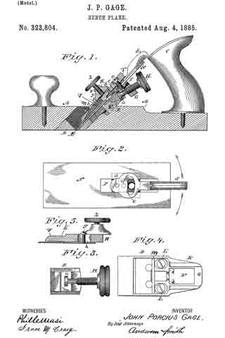
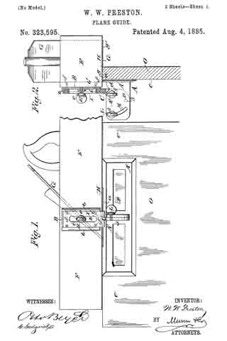
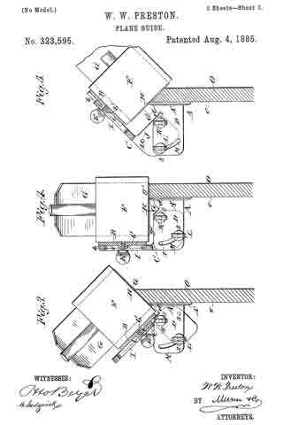
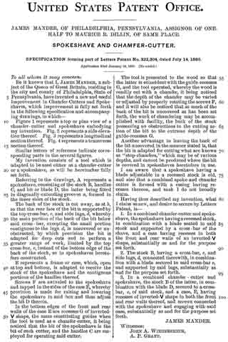
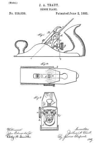
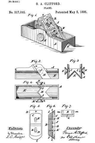
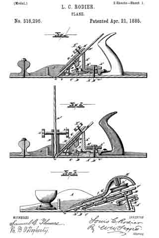
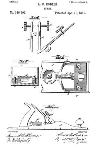
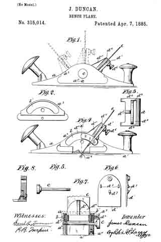
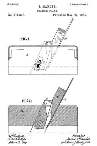
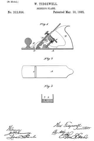
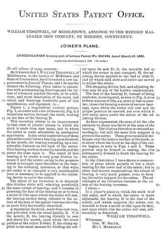
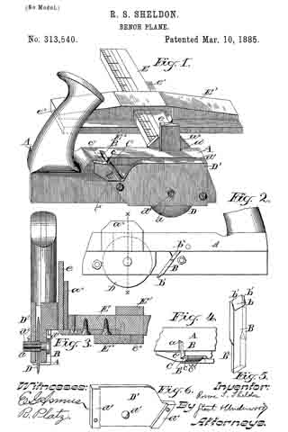
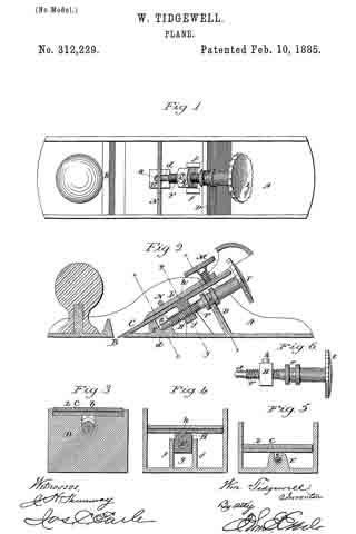
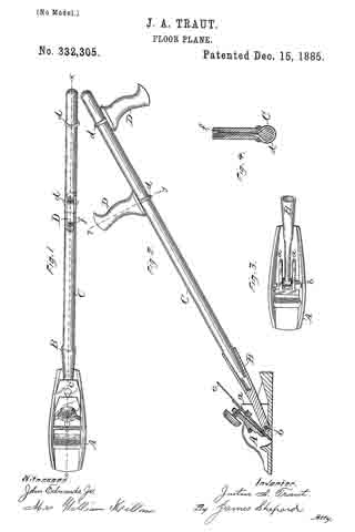
In the accompanying drawings, Figure 1 is a plan view of my plane. Fig. 2 is a vertical section of the plane on the line x x of Fig. 1, with a side elevation of its handle. Fig. 3 is a plan view of said plane with the cutting-bit and holding-cap removed; and Fig. 4 is a sectional view through the handle. on line y y of Fig. 2.

A designates the plane, which in its general features may be of any ordinary construction. The seat for the cutting-bit is formed mainly by the inclined upper surface of the two upright lugs a a. Between these lugs I pivot the socket B for the handle C by means of a bolt, b, which passes through said lugs a a and through an eye at the forward end of the socket B. This pivotal bolt b is located as near the bottom of the stock and as far forward under the cutting-bit c as is practicable, thereby causing the power applied through the handle C and stock B to be transmitted to the stock at such a point relatively to the cutting-edge of the bit as to hold said edge to its work, and thereby cause the plane to work smoothly. I provide the handle C at different points between its ends with two transverse handles, D D, one of which projects upwardly and the other downwardly, which handles are to be grasped by the hands of the operator when shoving the tool over the floor in planing. These handles I attach to the main handle by means of a yoke, d, and nut f, in the manner of attaching transverse handles to scythe-snaths, so that said handles D D may be adjusted to any desired position on the handle C for the convenience of the user.

I am aware that a prior patent shows a floor-plane having rollers at the front end of its stock and a long handle pivoted at the rear end of the stock at a point above the middle of its height, and that another patent shows a floor-plane having a yoke pivoted to its stock at a point about the middle of its height, and about half-way between the cutting-edge of the bit and the rear end of the stock, which yoke is provided with rollers at its lower end, a spring-finger at the top which presses on the forward end of the stock, and a socket which receives a long handle, said handle being provided at its rear end with a single transverse handle or cross arm. All of said prior art is hereby disclaimed.

I claim as my invention —

The herein-described floor-plane, consisting, essentially, of the plane A and the socket B, pivoted to the stock of said plane close to its bottom, underneath the cutting-bit, and just back ofthe cutting-edge of said bit, substantially as described, and for the purpose specified.

JUSTUS A. TRAUT.

Witnesses:
H. S. WALTER,
H. C. HINE.

No. 330,908 – Shuttle-Planer (Lodowick Leeds) (1885)

[paiddownloads id=”401″]330908


UNITED STATES PATENT OFFICE.

_________________

LODOWICK LEEDS, OF NEW LONDON, ASSIGNOR, BY MESNE ASSIGNMENTS,
TO BIRDIE L. FENNER, OF VERSAILLES, CONNECTICUT.

SHUTTLE-PLANER.

_________________

SPECIFICATION forming part of Letters Patent No. 330,908, dated November 24, 1885.
Application filed April 6, 1885. Serial No. 161,296. (No model.)

_________________

To all whom it may concern:

Be it known that I, LODOWICK LEEDS, a citizen of the United States, residing in the city and county of New London, and State of Connecticut, have invented certain new and useful Improvements in Shuttle-Planers, which improvements are fully set forth and described in the following specification, reference being had to the drawings hereunto annexed, in which —

Figure 1 is a side elevation of my new device. Fig. 2 is a top or plan view, and Fig. 3 end views, of the same. Fig. 4 is a side elevation of the plane used with my shuttle-holder, and Fig. 5 a detached view of thumb-screw k.

This invention relates to a new mechanical device by means of which loom-shuttles may be securely held and planed or trued up on one or more sides, as desired, my immediate object being to produce a portable device which may be easily understood and operated, and which maybe produced at a comparatively low price.

The constant reciprocating movement of the shuttle as it travels back and forth in the shuttle-box tends to so wear the sides and bottom of said shuttle that it becomes necesssary to frequently “true it up”, or, in other words, to bring said worn bottom and sides back again to a parallel with the longitudinal center of the shuttle. The universal tendency is to wear the shuttle near each end, leaving the center somewhat full or rounded, and causing said shuttle as it travels to wabble and vibrate, instead of shooting across in a straight line. So far as I am acquainted with the state of the art, it has been the custom heretofore to either true up such worn shuttles with an ordinary bench-plane, or by an expensive machine in which the cutting is done by a swiftly-revolving cutter.

My device consists, in brief, of a metallic frame in which the shuttle is held on centers, and which is so formed that when one side of the shuttle is trued up said entire frame may be turned over to plane the opposite side before removing the shuttle.

It further consists of means for holding and squaring up said shuttle in the frame, and of an attachment by which the plane used may be raised or lowered at will by the operator, all of said improved features being described in full hereinafter.

In the accompanying drawings, A represents my shuttle-holding frame, made preferably of cast metal and in form resembling the bed of hand-lathes as commonly constructed. This frame A is drilled at one end, as at a, to provide a holding center for one of the metallic tips of the shuttle. The opposite end is drilled and tapped to receive a strong thumb-screw, b, whose inner end is cupped to provide a holding center for the other end of the shuttle, said screw b also furnishing the necessary adjustment, so that shuttles of varied lengths may be held in the same frame. Said frame is drilled and tapped on each side, at or near its center, to receive thumb-screws c d, whose inner ends are provided with loosely-fitting washers e e. When the shuttle is placed in frame A and held by its tips in the centers above described, (see Fig. 2,) the screws c d are advanced to lock said shuttle firmly in place and prevent all tendency to rock or rotate. Both the upper and lower sides of frame A are carefully planed up, forming ways or guides h h’ for the plane B to travel on.

I use preferably an iron plane of the form commonly known as the “Bailey plane,” having means for ready adjustment of the iron, and to such a plane I attach a metallic frame, C, which is so arranged that the plane may be readily lowered to reach the shuttle as said shuttle is being planed. The frame C extends along each side of the plane, being supported by screws i, which pass through diagonal slots in said frame and into the plane-frame. At the rear end of the plane is a thumb-screw, k, which is tapped into the handle or frame of the plane, and is provided with a grooved shoulder, m, which straddles the slotted rear end of frame C. (See Fig. 5.) It will now be understood that as thumb-screw k is turned to unscrew, it draws rearward with it frame C, which, owing to its diagonal bearing-slots, rises on the plane, or, if in place on the ways h, allows said plane to be slowly depressed to reach the shuttle.

My device is used as follows: The frame A is secured to a suitable bench or table, or is so placed that one end abuts against a bench-hook or other fixture on said bench, The shuttle having been securely fastened in centers a b, and squared up by the screws c d, the plane is now moved across, with the frame C resting on ways h or h’. If the plane-iron does not reach the shuttle to effect a cut, screw k is turned to lower the plane until the iron engages and trims the highest point of the shuttle. The plane is then dropped gradually, cutting slightly lower at each movement until the side of the shuttle is properly trued up and straightened. The plane being now removed for an instant, frame A is overturned, so that ways h’ come to the top side, when the operation above described is repeated.

By thus truing up the shuttle on centers, and without removing it from its supporting-frame, I am able to do the work quicker and better than heretofore, cutting off only stock enough to bring the sides parallel with each other and with the longitudinal center of the shuttle. Iam also able to true up a number of shuttles to precisely the same size and shape and approximately to the same weight, which is a desirable accomplishment where a series of shuttles are to be used in the same loom.

Having thus described my invention, I claim —

1. A device for holding a shuttle while in the act of planing or truing up the same, consisting of a frame provided with cup centers to support said shuttle by its tips, and means for squaring up and holding said shuttle, said supporting-frame being so provided with ways or guides on two opposite sides that the shuttle may be planed on two sides without removal from said frame, all substantially as described, and for the purpose specified.

2. In combination with a frame having ways or guides on two opposite sides, cup centers to support a shuttle by its tips, adjustable supports to square up and hold said shuttle on its sides, and a plane adapted to travel on said guides or ways, and provided with means by which said plane may be elevated or depressed, substantially as and for the purpose specified.

LODOWICK LEEDS.

Witnesses:
FRANK H. ALLEN,
JOHN H. KEEP.

No. 326,435 – Beading-Tool (Elton P. Kendall And Ambrose S. Vose) (1885)

[paiddownloads id=”400″]326435


UNITED STATES PATENT OFFICE.

_________________

ELTON P. KENDALL AND AMBROSE S. VOSE, OF WINDSOR, VERMONT.

BEADING-TOOL.

_________________

SPECIFICATION forming part of Letters Patent No. 326,435, dated September 15, 1885.
Application filed March 28, 1885. (No model.)

_________________

To all whom it may concern:

Be it known that we, ELTON P. KENDALL and AMBROSE S. VOSE, both citizens of the United States, residing at Windsor, in the county of Windsor and State of Vermont, have invented certain new and useful lmprovements in Beading-Tools; and we do declare the following to be a full, clear, and exact description of the invention, such as will enable others skilled in the art to which it appertains to make and use the same, reference being had to the accompanying drawings, and to letters or figures of reference marked thereon, which form a part of this specification.

Figure 1 of the drawings is a vertical longitudinal seotion. Fig. 2 is a plan view. Fig. 3 is a detail view.

This invention relates to improvements in tools for cutting the beads and grooves of moldings and rosettes, and is adapted to be used on either wood, stone, or iron.

The invention consists, essentially, in firmly binding, edge to edge, in a metallic block a number of bar-shaped cutters or chisels, the cutting ends of which are formed and arranged to constitute the reverse of the contour of the molding, or one-half of the contour of the rosette to be formed.

The invention further consists in the construction of the cutting-edges of the chisels hereinafter described.

Referring to the accompanying drawings by letter, A represents a block of iron or steel, having on one of its side surfaces a shallow rectangular recess or out-away portion, A’.

A2 is a rectangular vertical recess in the floor of the recess A’, adjoining one side thereof, and for a purpose hereinafter explained.

B B are similar handles extending laterally from the side edges of the block A, and B’ is a plate adapted to be secured to the block A by the screws b b, so as to cover the recess A’ and bind the chisels, hereinafter described, between itself and the block in said recess.

C C, &c., are bar-shaped cutters or chisels of steel, rectangular in section, and with their sides parallel, so as to lie in the recess A’ with their sides pressed equally at all points by the block and plate B’. Their edges are also parallel, so that they will be bound together by the pressure of the set-screw D, which passes through a threaded opening in the edge of the block below the handle B on the edge opposite the recess A2.

The ends of the chisels may be made concave, convex, rectilinear at various inclinations, or of any desired contour; but whatever the contour of the end, its surface forms at all points a right angle with each side, so that the end has two cutting edges, c c, each of which has a pitch of ninety degrees. By this means the chisels may make either a draw cut or a push cut, according to the direction in which the block is moved, (the inclination being varied to suit the direction,) and, to complete the contour of the moldings, would make a draw cut and a push alternately.

The chisels, as is evident, are longitudinally adjustable, either separately or together in the block, and preferably have both ends provided with cutting-edges, as shown.

C’ is a modification of the ends of the chisels. In this case the vertical section of the end shows a U-shaped contour, the edges having a less pitch than ninety degrees.

One of the cutting-edges c may, if desired, be provided with the ricks c’ c’, to adapt it for certain kinds of work.

E is a bit having a rectangular shaft, e, and provided with the centering-point e’ and head e2’ on its lower and upper end, respectively. The shaft of the bit is held in the recess A2 by the plate B’, and its head is held for insertion into a brace or bit stock by which the bit and consequently the block and chisels are turned when forming a rosette. When the tool is used for moldings, the bit is removed and a rectangular shaft of the same diameter inserted in its place, against which shaft the chisels abut.

F is a gage-square laterally adjustable on the block by means of a proper slot and the set-screw f. The square is set so that its foot f’ will rest against the top or bottom of the molding and bring the chisels to the desired place. When turning rosettes,the gage-square is detached.

It is evident from the foregoing that any contour of molding or rosette may be formed by selecting the proper chisels and adjusting them to proper positions in the block A. Rosettes or moldings of different widths may be formed by binding on the block a greater or less number of chisels.

Having thus described this invention, what we claim is —

1. The improved beading-tool herein described, consisting of the holder-block A, recessed as shown, to receive the cutters, and having the recess E to receive the centering-bit, the plate or bar B’, adapted to secure the cutters and bit in their respective seats, and the set-screw D, passing through the threaded aperture in the holder-block to bind the cutters together, substantially as specified.

2. In a beading-tool, the combination, with the holder-block having the transverse recess to seat the cutters, of the plate B’, adapted to secure the cutters therein, and provided with a recess to receive a gage-square, the gage-square F, arranged at right angles to the cutters in the said recess, and the screw f, for adjustably securing the same therein, substantially as set forth.

In testimony whereof we affix our signatures in presence of two witnesses.

ELTON P. KENDALL.
AMBROSE S. VOSE.

Witnesses:
JOS. C. ENRIGHT,
GILBERT A. DAVIS.

No. 325,571 – Spokeshave (Charles William Smith) (1885)

[paiddownloads id=”399″]325571


UNITED STATES PATENT OFFICE.

_________________

CHARLES WILLIAM SMITH, OF WESTERLY, RHODE ISLAND.

SPOKESHAVE.

_________________

SPECIFICATION forming part of Letters Patent No. 325,571, dated September 1, 1885.
Application filed June 27, 1885. (No model.)

_________________

To all whom it may concern:

Be it known that I, C. W. SMITH, a citizen of the United States, residing at Westerly in the county of Washington and State of Rhode Island, have invented certain new and useful Improvements in Tool-Holders; and I do declare the following to be a full, clear, and exact description of the invention, such as will enable others skilled in the art to which it appertains to make and use the same, reference being had to the accompanying drawings, and to letters or figures of reference marked thereon, which form a part of this specification.

Figure 1 of the drawings is a representation of this invention, and is a front view. Fig. 2 is a view of the under side. Fig. 3 is a longitudinal section taken in line with the set-screws and studs when held vertically.

This invention relates to tool-holders of the class commonly termed “spokeshaves;” and it consists in the construction and novel arrangement of devices, all as hereinafter fully described, and particularly pointed out in the claim.

Referring by letter to the accompanying drawings, A designates the tool-handle, having the usual arms, B B. The middle portion, G, of the tool-holder is provided with a throat, D, for the tool or blade E. At each end of the throat D is provided a hollow stud, F, Which communicates at its lower end with the throat D, and is threaded internally in its upper end for the reception of a set-screw, H, a screw, H, being employed in each hollow stud F. The lower portion of each hollow stud is provided with an opening, H’, which conununicates with the throat D of the tool-holder.

In the bottom of each stud F is placed a key, I, the upper end of which is cylindrical in cross section. The keys I I are beveled at one side to cause them, when in proper position in their seats, to bear against the edges of the bits J when the screws H H are turned down upon them to hold the bit K in place in the throat D of the tool-holder, and in the position to which the latter may have been adjusted.

To adjust the bit K the set-screws must be loosened, the bit moved, and the set-screws H H must be again tightened.

This construction is simple, and the parts are positive in their action.

Having thus fully described my invention, what I claim as new, and desire to secure by Letters Patent of the United States, is —

The combination, with the tool-handle having the throat and the hollow studs having threaded upper portions, and the open lower portions communicating with the throat of tool-handle, of the keys I I, provided with longitudinally-beveled faces, and the set-screws for operating the keys to engage the lateral edges of the cutter, substantially as specified.

In testimony whereof I attire my signature in presence of two witnesses.

CHARLES WILLIAM SMITH. [L. S.]

Witnesses:
JOS. W. BRYANT,
WM. H. BRYANT.

No. 323,804 – Bench-Plane (John P. Gage) (1885)

[paiddownloads id=”398″]323804


UNITED STATES PATENT OFFICE.

_________________

JOHN P. GAGE , OF VINELAND, NEW JERSEY.

BENCH-PLANE.

_________________

SPECIFICATION forming part of Letters Patent No. 323,804, dated August 4, 1885.
Application filed April 23, 1885. (Model.)

_________________

To all whom it may concern:

Be it known that I, JOHN P. GAGE, a citizen ofthe United States, residing at Vineland, in the county of Cumberland and State of New Jersey, have invented certain new and useful Improvements in Bench-Planes; and I do declare the following to be a full, clear, and exact description of the invention, such as will enable others skilled in the art to which it appertains to make and use the same, reference being had to the accompanying drawings, and to letters or figures of reference marked thereon which form a part of this specification.

Figure 1 of the drawings is a representation of a longitudinal section of my invention. Fig. 2 is a view of the cutter and the pivoted finger-lever removed from the plane. Fig. 3 is a view of the adjusting-screw and cutter-bearing removed. Fig. 4 is a detached view of the bearing-plate, and Fig. 5 is a sectional view of the fellow plate and cup-plate with the bearing-screw and casting applied.

This invention has relation to improvements in carpenters’ planes; and it consists in certain novel devices, as hereinafter set forth, and pointed out in the appended claims.

In the accompanying drawings, the letter A designates the body of the plane, which is formed with an oblique transverse slot, B, for the cutter and its. adjusting devices. C is the handle.

D is a metal bearing, which is set into the oblique slot B, and is secured therein. The lower face of this bearing is flush with the bearing-face of the plane-body, and may be made a little concave in its middle portions, or between its front and rear bearing-edges. This metal bearing is provided with an extension, E, backward and upward, which is slotted at F, and has a threaded bearing at G for the adjusting-screw H. It is also provided with lateral stops K.

L L are the elongated openings or slots through which the fastening-screws pass. A transverse bearing, m, is provided, usually in rounded or rod form, which is located upward and forward from the main face of the casting, on which the cutter rests.

N is the cutter, slotted at P, and provided with an under bearing, R, which is designed to engage the enlarged end a of the adjusting-screw. This bearing descends into the opening B of the casting D when the cutter is applied in position.

S is a lever having its fulcrum-bearing c in the slot of the cutter, and engaging a stud, d, of the bearing B, or of its fellow plate T, which is firmly secured to said bearing B, usually by a screw, e. The handle of the lever S projects backward and upward within easy reach of the fingers. The object of this lever movement is to enable the operator to adjust the cutter laterally, so that when its cutting-edge is inclined or out of trim a single movement of the lever to the right or left, as the case may require, will correct the deviation and bring the cutting-edge into true relation with the bearing-face of the plane. Other forms of lever-connections may be employed with the cutter, or the adjustment may be made by means of lateral screws, or a screw may be employed, extending downward and forward, to operate an eccentric in connection with the cutter. Many devices to effect this lateral adjustment of the cutter-plate will occur to those skilled in the art.

V is the cap-plate, which is adjustable by means of screws g g passing through siots h h, in the fastening-piece or top casting, V, which carries the bearing-screw Z. This top V is formed with a concave rounded bearing, k, adapted to engage the transverse rod an and hold the fastening-piece or cap-plate firmly in position.

Having described this invention, what I claim, and desire to secure by Letters Patent, is —

1. In a plane, the combination of the slotted cutter, the under bearing, B, having a stud, d, and operated by means of the adjusting-screw, the fellow plate, screw connecting the fellow plate and bearing R, lever S, and its fulcrum-bearing c, arranged in the slot of the cutter, substantially as specified.

2. The combination of the slotted cutter, a bearing arranged beneath the same, with a stud passing through the slot of the said cutter, a fellow plate connected with the said under bearing, the finger-lever, and its fulcrum-bearing, as c, arranged in the slot, wherby lateral deviations of the cutting-edge may be corrected, substantially as specified.

3. A plane having an lever adapted to correct deviations in the edge of the cutter, which lever has its lower end pivoted in a longitudinal slot of the cutter, and provided with a stud to engage and move laterally a fulcrum-bearing in the said slot, substantially as specified.

In testimony whereof I affix my signature in presence of two witnesses.

JOHN P. GAGE.

Witnesses:
THEO. MUNGEN,
PHILIP C. MASI.

No. 323,595 – Plane-Guide (William Wallace Preston) (1885)

[paiddownloads id=”397″]323595


UNITED STATES PATENT OFFICE.

_________________

WILLIAM WALLACE PRESTON , OF COLDWATER, ASSIGNOR TO HIMSELF
AND EDWARD FLOYD PRESTON, OF BISMARCK, MICHIGAN.

PLANE-GUIDE.

_________________

SPECIFICATION forming part of Letters Patent No. 323,595, dated August 4, 1885.
Application filed January 3, 1885. (No model.)

_________________

To all whom it may concern:

Be it known that I, WILLIAM WALLACE PRESTON, of Coldwater, in the county of Branch, and State of Michigan, have invented a new and Improved Plane-Guide, of which the following is a full, clear, and exact description.

The object of my invention is to provide a simple, inexpensive guide or device of improved construction, for attachment to planes, to enable the edges of lumber to be squared or to be beveled at any desired angle either way by the planes, with accuracy and without the aid of a try-square or bevel, and with economy of time and labor.

The invention consists in particular constructions and combinations of parts of the plane-guide and its attachments to the plane, all as hereinafter fully described and claimed.

Reference is to be had to the accompanying drawings, forming part of this specification, in which similar letters of reference indicate corresponding parts in all the figures.

Figure 1 is a side elevation showing my improved plane-guide attached to a plane, as in use in squaring the edge of a board. Fig. 2 is a rear end sectional view of the same. Fig. 3 shows in end view the plane and its guide adjusted to bevel the edge of a board downward toward its finished face. Fig. 4 is an end view with the plane and its guide adjusted to utilize the outer part of the sharp edge of the plane-iron; and Fig. 5 is an end view illustrating the adjustment of the plane and its guide for beveling the edges of boards downward and backward from their finished faces.

The plane-guide in its preferred form consists, mainly, of three meta! parts: the fence A, or guide proper, the plate B, which is to be fixed to the side of the plane-stock, and the part C, which connects the parts A B by the aid of thumb-screws in the various adjustments of the plane-guide, as hereinafter more fully explained.

The fence A consists of a plate, A’, made either solid throughout or cut away at various places to decrease its weight, and having a strong flange, D, projecting at a right angle and in vertical plane from its back or outer face, and preferably from about the center of the plate A’ (See Fig. I.) I prefer to make the plate B with flanges b b at opposite edges, and to form a boss, b’, at the center of its face, to give sufficient body of metal to firrnly hold a thumb-screw, E, which is threaded into the boss. I attach the plate B by screws f, or otherwise, and it may be permanently, to the side of the stock F of the plane, and preferably near where the plane-iron or cutter G passes through the working-face H of the plane, and so that the flanges b b range up and down the side of the plane. The connecting-piece C is made with an upper portion, I, fitted to slide on the plate B between its flanges b b, and having a slot, i, through which the screw E passes, the flange or shoulder e of the screw being wider than the slot, so it may bind the part I to the plate B at any desired adjustment. The lower part, J, of the connection C is in the form of a flange which projects to one side or face of the upper part I, and in a plane at a right angle with said part, I, and so part J may lie face to face with the flange D of the fence A and be fastened to it by the thumb-screws K L, the screw K serving, when loosened, as a pivot on which to swing the parts A C to their various angles of adjustment, and the screw L, which passes through a curved slot, M, of plate D, serving, with the tightened screw K, to bind the parts C A firrnly together when set. The screws K L enter threaded holes in the lower part or flange, J, of the connection C. I cut away the upper edge of the fence-plate A’, as at a, and for a depth a little greater than the maxirnum projection of the plane-iron G from the plane-face H, so that said face always may lie closely on the upper edge of the fence-plate, and the pivot-screw K is located in such relation to the parts A C of the plane-guide that the corner of the plane-iron nest the guide always will project inward beyond the contacting faces of the fence A and the board O to be jointed, as seen best in Figs. 2 and 3. The adjustment and operation of my improvement are as follows: In jointing the edges of boards O squarely with their finished face o, against which the fence-plate A is held and moves as the plane is operated, or in jointing at a slight back bevel or undercut suitable for the edges of base-boards, door-jambs, and the like, or in jointing at any bevel from forty-five degrees (more or less) downward toward the face o of the work, the part C will be adjusted with its lower part or flange, J, outward, so that the screw K may be entered into the threaded hole 1 of said flange, as shown in Figs. 2 and 3. In square-jointing the boards the fence-plate A’ will be set square with the edge of the plane-iron when the screw E binds the parts C B together, so that the plane-face H rests on the top of the fence-plate A’, as seen in Fig. 2, and the screw L then will be passed through the slot M into the threaded hole 2 of the flange J, and the screws K L then are tightened and the plane is ready for work. To bevel the edge of the board O under slightly toward the back, the screws E K L will be loosened and the plane will be swung over to the right hand on pivot K, or the fence A swung under the plane to the desired angle, and the screws K L will be tightened. The loose screw E, which had allowed the plate B to lift or draw upward on the part I of connection C, will then be tightened, when the plane-face H rests on the upper edge of the fence-plate A’, and the plane is ready for work. To bevel the edge of the board O downward toward its face o, the screws K L will be loosened, and the connection C and the plane will be swung downward to the left hand, the screw L then moving through the slot M, and when the plane-face H stands at the desired angle with the working-face of the fence-plate A’, the screws K L will be tightened; but this adjustment throws the plane-face H away from the fence-plate A’, and to bring them in contact the screw E will be loosened, so that the part I of connection C may be slid upward, or the plane and its plate B be slid downward until the plane-face H rests against the top of the fence-plate A’, the flange D being out away at d to allow this adjustment, and the screw E then will be tightened and the plane is ready for work, as seen in Fig. 3, which shows the tool set to joint the edge of the board at an angle of forty-five degrees; but the adjustments to work at angles greater or less than that shown may readily be made as the work to be done shall require. In squaring or slightly back-beveling the edges of the boards, with the pivot-pin K entered in the screw-hole 1 of the flange J, as in Fig. 2, the left-hand side or edge portion, g, of the plane-iron G will be used, and to provide for utilizing the right-hand sharp edge portion, g’, of the iron when the portion g becomes dulled by use so as to avoid frequent whetting or sharpening of the iron, and also to provide for jointing the boards at a considerable back bevel, the connection C will be reversed in position, and the pivot-screw K will be entered into the screw-hole 2, and the screw L will be turned into the screw-hole 3 of the flange portion J of connection C, as in Figs. 4 and 5. In squaring the edges with the part g’ of the plane-iron, as in Fig. 4, the screws K L will be tightened when the screw L is at or near the lower part of the slot M of flange D; but in setting the plane over to joint at a back downward bevel at any desired inclination from a square edge to an angle of forty-five degrees or more, the screw L will move upward in the slot M, more or less, as required, and the screw E will be tightened when the face H of the plane rests on the top edge of the fence-piece A’. In Fig. 5 the plane is set to back-bevel the lumber at an angle of forty-five degrees.

It will be seen that in every described adjustment of the plane and guide the plane-face is in contact with the guide fence-piece A’, and that it only is necessary in using the plane to hold the fence-piece flat against the finished face of the lumber to secure accurately squared or beveled edges of the lumber, and without the inconveniences and delays incident to the use of try-squares or bevels, thus enabling the workman to do more accurate work and a largely-increased amount of it in a given time.

If desired, the plate B may be let in flush with the side face of the plane, and when a plane is to be used for squaring or for beveling at one angle only, the plate B may be dispensed with and the upper plate or part, I, of the connection C will then be fastened directly to the side of the plane-stock; but the use of the plate B and screw E is preferred for securing the various adjustments allowed by them with a single plane, as above described.

Any suitable fastenings may be substituted for the thumb-screws K L which will serve their purpose — such as nutted bolts; but the thumb screws are preferred because of their convenience in effecting the adjustments of the plane-guide.

Having thus described my invention, what I claim as new, and desire to secure by Letters Patent, is —

1. A plane-guide comprising a fence, A, formed of a plate, A’, having a flange, D, provided with a curved slot, M, and a set-screw, K, passing through the said flange in the same horizontal plane as the upper end of the slot, a reversible connecting-piece, C, formed with the lower flange, J, and upper plate, I, in planes at right angles to each other, the said flange J having holes 1 and 2 in horizontal alignment, and the set-screw L, whereby the set-screw K may serve as a pivotal point and the set-screw L the adjusting point to allow of adjustments, substantially as set forth.

2. A plane-guide comprising a fence, A, formed of a plate, A’, having a flange, D, provided with a curved slot, M, and a set-screw, K, passing through the said flange in the same horizontal plane as the upper end of the slot, a reversible connecting-piece, C, formed with the lower flange, J, and upper plate, I, in planes at right angles to each other, the said flange J having holes 1 and 2 near its upper edge in the same horizontal plane, and a hole, 3, near its lower edge, and the set-screw L, adapted to engage either one of the said holes, for adjustment when one of the other holes is engaged by the set-screw K as a pivotal point.

3. In a plane-guide, the combination, with the fence A and its flange D at right angles therewith, of the reversible connecting-plate C, having a flange, J , in the plane of flange D, and adljustably pivoted to said flange D, and a binding-screw for locking said parts in their adjusted positions, substantially as set forth.

WILLIAM WALLACE PRESTON.

Witnesses:
WM. H. BENEDICT,
GEO. T. CULVER.

No. 322,304 – Spokeshave And Chamfer-Cutter (James Mander) (1885)

[paiddownloads id=”396″]322304


UNITED STATES PATENT OFFICE.

_________________

JAMES MANDER, OF PHILADELPHIA, PENNSYLVANIA, ASSIGNOR OF
ONE-HALF TO MAURICE R. DILLIN, OF SAME PLACE.

SPOKESHAVE AND CHAMFER-CUTTER.

_________________

SPECIFICATION forming part of Letters Patent No. 322,304, dated July 14, 1885.
Application filed January 24, 1885. (No model.)

_________________

To all whom it may concern:

Be it known that I, JAMES MANDER, a subject of the Queen of Great Britain, residing in the city and county of Philadelphia, State of Pennsylvania, have invented a new and useful Improvement in Chamfer-Cutters and Spoke-shaves, which improvement is fully set forth in the following specification and accompanying drawings, in which —

Figure 1 represents a top or plan view of a chamfer-cutter and spokeshave embodying my invention. Fig. 2 represents a side elevation thereof. Fig. 3 represents a longitudinal section thereof. Fig. 4. represents a transverse section thereof.

Similar letters of reference indicate corresponding parts in the several figures.

My invention consists of a tool which is adapted to be used either as a chamfer-cutter or a spokeshave, as will be hereinafter fully set forth.

Referring to the drawings, A represents a spokeshave, consisting of the stock B, handles C, and bit or blade D, the latter being fitted in diagonally-extending grooves a, formed in the inner sides of the stock.

The back of the stock is cut away, as at b, so that the rear face of the bit is supported by the top cross-bar, c, and side lugs, d, whereby the main portion of the back of the bit below said cross-bar, excepting the small portion contiguous to the lugs d, is uncovered or unobstructed, by which provision the bit is adapted for deep cuts and to perform a greater range of work, limited by the top cross-bar, c, instead of the bottom edge of the back of the stock, as in spokeshaves heretofore constructed.

E represents a frame or case, which, open at top and bottom, is adapted to receive the stock of the spokeshave and the contiguous portions of the handles thereof.

Screws F are swiveled to the spokeshave and tapped in the sides of the case E, whereby provision is made for raising and lowering the spokeshave in said box and thus adjust the bit D therein.

In the bottom edges of the front and rear walls of the case E are recesses G of inverted-V shape, the same constituting guides when the tool is used as a chamfer-cutter, it being noticed that the bit of the spokeshave is the bit of such cutter, and the handles C are employed for operating said cutter.

The tool is presented to the wood so that the latter is coincident with the guide-recesses G, and the tool operated, whereby the wood is readily cut with a chamfer, it being noticed that the depth of the chamfer may be varied or adjusted by properly rotating the screws F, and it will also be noticed that as much of the back of the bit is uncovered as has been set forth, the work of chamfering may be accomplished with facility, the back of the stock presenting no obstructions to the cutting action of the bit to the extreme depth of the guide-recesses G.

Another advantage in leaving the back of the bit uncovered in the manner stated is, that the bit is adapted for cutting what are known as “stop-chamfers,” which may be of various depths, and cannot be produced where the bit is covered in spokeshaves heretofore in use.

I am aware that a spokeshave having a blade adjustable in a recessed stock is old, and also that a combined spoke and chamfer cutter is formed with a casing having recesses thereon, and such I do not broadly claim.

Having thus described my invention, what I claim as new, and desire to secure by Letters Patent, is —

1. In a combined chamfer-cutter and spoke-shave, the spokeshave having a recessed stock, in combination with a blade seated in said stock and supported by a cross-bar of the shave, and a case having recesses in both the front and rear walls of an inverted-V shape, substantially as and for the purpose set forth.

2. The stock B, having a cross-bar, c, and side lugs, d, connected therewith, in combination with a blade secured to said cross-bar c, and supported by said lugs, substantially as and for the purpose set forth.

3. In a combined chamfer-cutter and spokeshave, the stock B of the latter, in combination with the blade D, secured to a cross-bar, c, of said stock, and a case, E, having recesses of inverted-V shape in both the front and rear walls thereof, and screws connected with the spokeshave and engaging with said case, substantially as and for the purpose set forth.

JAMES MANDER.

Witnesses:
JOHN A. WIEDERSHEIM,
A. P. GRANT.

No. 319,161 – Hand-Beader (Orlando E. Williams And Lawrence V. Poole) (1885)

[paiddownloads id=”395″]319161


UNITED STATES PATENT OFFICE.

_________________

ORLANDO E. WILLIAMS AND LAWRENCE V. POOLE, OF WINDSOR, VT.

HAND-BEADER.

_________________

SPECIFICATION forming part of Letters Patent No. 319,161, dated June 2, 1885.
Application filed March 28, 1885. (No model.)

_________________

To all whom it may concern:

Be it known that we, O. E. WILLIAMS and L. V. POOLE, of Windsor, in the county of Windsor and State of Vermont, have invented an Improved Hand-Beader, of which the following is a specification.

The special object of the invention is to make the tool and holder conveniently adjustable to either side of a stationary guide, so that it may be adapted to suit the grain of the wood and make central beadings in thick boards. This object is accomplished by constructing and combining the parts of a header, as hereinafter described.

Figure 1 of the drawings is a plan view; Fig. 2, a central cross-section; Fig. 3, a detail view of the cutter plate or holder, and Fig. 4 a detail view of the guide-piece. Fig. 5 shows a combination of cutters.

In the drawings, A represents the two-handed stock provided with the longitudinal groove a; B, the cutter plate holder having the longitudinal slot b to be arranged over the groove a. It also has a downwardly-extending flange, b’, to prevent lateral displacement and holes b2 b2 near the ends, so as to be secured to the stock by clamp-screws C C.

D is the cutter-plate, and E the cutter-disk, the latter clamped to the former by the thumb-nut e, headed screw e’, and washer e2. The screw e’ is passed with its point up through the slot D, while the opposite parallel sides of its head are within the groove and rest upon the ledges b3 b3. Thus it will be seen that the screw is locked so that it cannot turn, but can be slid along when the nut is loosened.

F is the guide, which is provided with a right-angled arm, f that is held by a screw, f’, to the stock A.

By loosening the nut e the cutter-disk and cutter-plate may be slid so as to bring the beader-points on either side of the guide F, as may be desired.

Having thus described all that is necessary to a full understanding of our invention, what we claim as new, and desire to protect by Letters Patent, is —

A hand-beader having a stock or handle that has a longitudinal groove in its upper side, a fixed guide secured near the center of stock on the front of it, a metal plate secured to the stock on its upper side and having a longitudinal slot corresponding with the groove in the stock and fitting over it, a screw with its head resting loosely in said groove and under said plate with its shank passing up through the slot in the plate, a cutter-plate and a cutting-disk resting successively above said metal plate, each having an opening to receive the shank of the screw, and a thumb-nut engaging the end of the screw, whereby the clamps may be so adjusted as to bring the beading-points on either side of the guide, as set forth.

ORLANDO E. WILLIAMS.
LAWRENCE V. POOLE.

Witnesses:
HUGH GILGHRIST,
H. M. HUBBARD.

No. 319,039 – Bench-Plane (Justus A. Traut) (1885)

[paiddownloads id=”394″]319039


UNITED STATES PATENT OFFICE.

_________________

JUSTUS A. TRAUT, OF NEW BRITAIN, CONNNECTICUT.

BENCH-PLANE.

_________________

SPECIFICATION forming part of Letters Patent No. 319,039, dated June 2, 1885.
Application filed June 16, 1884. (Model.)

_________________

To all whom it may concern:

Be it known that I, JUSTUS A. TRAUT, a citizen of the United States, residing at New Britain, in the county of Hartford and State of Connecticut, have invented certain new and useful Improvements in Bench-Planes, of which the following is a specification.

My invention relates to improvements in bench-planes of the class patented to Leonard Baiiey, August 6, 1867, No. 67.398, and my object is to effect the lateral and endwise adjustments of the cutting-bit by two different movements of a single lever, and I accomplish this object by the construction illustrated in the accompanying drawings, in which —

Figure 1 is a side elevation of my improved plane. Fig. 2 is a sectional view, partly in elevation, on line x x of Fig. 1, and Fig. 3 is a vertical sectional view, partly in elevation, on line y of Fig. 1.

With the exception of certain changes and additions hereinafter described, my improved plane is the same as the Bailey planes now in the rnarket. The adjusting-nut g is the same as heretofore rnade, except in that its shoulders b b are wider. The prongs of the bifurcated lever c are spread far enough apart to allow a lateral rnovernent of said lever bodily without disengaging the shoulders of the adjusting-nut. The lugs d d are placed upon the under side of the frog or plane seat A, somewhat farther apart than in said prior planes, and are provided with smooth-bored holes for the insertion of the adjusting-screw a, which screw also constitutes the axle for the lever c.

This lever c is furnished with a screw-threaded hole within which the adjusting-screw a is fitted. As in prior planes. the upper end, e, of the lever c enters a slot, f in the cap-iron, which slot is made shorter than formerly, and of a size which the end e of the lever c will substantially fill in both directions, so that a movement of said end either laterally or up and down will carry the cap-iron with it. Upon the adjusting-screw a, I have placed the nuts h h, which allow the free rotation of the adjusting-screw upon its axis, but which will not permit of any longitudinal movement.

The bit and cap-iron of the plane are set in their places upon the frog or plane-seat in the ordinary manner. The holding-cap B is then put into its proper place, and clamps the bit and cap-iron firnlly against the frog or plane-seat, said holding-cap pressing them at each end. The point of pressure at the lower end of the cap is the point where the bit or cutter will pivot when its upper end is moved edge-wise. The bit is adjusted up or down the same as heretofore.

To adjust the cutting-bit or cutter edgewise to square its cutting-edge with the stock, I have only to turn the adjusting screw a one way or the other, as may be desired, which movenment of the adjusting-screw acts upon the screw-thread of the bifurcated lever, and causes said lever to move bodily to the right or left, and thus more the cup-iron and bit or cutter with which it is engaged, and thereby give the required adjustment.

I am aware that prior devices have been invented to adjust the bit edgewise to bring its cutting-edge square with the stock, and therefore I do not claim the same, broadly.

I claim as my invention —

In combination, in a suitable supporting-frame, a bit having a central longitudinal slot, a cap iron secured to said bit by a screw passing through said slot and engaging said cap-iron, a holding-iron for clamping the bit in place, and an adjusting lever pivotally secured upon a horizontal screw-shaft which passes through lugs upon the under side of the upper end of said supporting-frame, and is secured against horizontal movement and capable of rotary increment only, the upper end of which lever passes through said frame and engages with a slot or mortise in the cap-iron, the said lever so secured having an up and down movement by an adjusting-nut located under said frame, and a lateral movement by a thumb-piece or similar operating-handle on the end of said screw-shaft, all being substantially as herein described, and for the object specified.

JUSTUS A. TRAUT.

Witnesses:
H. S. WALTER,
HENRY C. HINE.

No. 318,331- Adjustable-Faced Plane (Edwin Walker) (1885)

[paiddownloads id=”393″]318331


UNITED STATES PATENT OFFICE.

_________________

EDWIN WALKER, OF ERIE, PENNSYLVANIA.

ADJUSTABLE-FACED PLANE.

_________________

SPECIFICATION forming part of Letters Patent No. 318,331, dated May 19, 1885.
Application filed February 6, 1885. (No model.)

_________________

To all whom it may concern:

Be it known that I, EDWIN WALKER, a citizen of the United States, residing at Erie, in the county of Erie and State of Pennsylvania, have invented certain new and useful Improvements in Adjustable-Faced Planes; and I do hereby declare the following to be a full, clear, and exact description of the invention, such as will enable others skilled in the art to which it appertains to make and use the same, reference being had to the accompanying drawings, and to the letters of reference marked thereon, forming part of this specification.

My invention relates to improvements in plane-stocks and mechanism connected therewith; and it consists of the improvements hereinafter set forth and explained.

Figure 1 is a perspective view of my improved plane. Fig. 2 is a perspective view of my improved plane-stock frame with the adjustable plates and other mechanism thereof removed therefrom. Fig. 3 is a side elevation of the back half of my improved plane-stock with a portion of the adjustable plates removed, so as to show the bit-adjusting mechanism. Fig. 4 is a perspective view of one of the central adjustable plates, showing a groove therein for the bit-adjusting mechanism. Fig. 5 shows a front end view of my improved plane with a gage attached thereon for adjusting the depth of cut, and also showing the plane adjusted to a square-faced bit. Figs. 6, 7, 8, 9, 10, and 11 are front end views of my improved plane-stock, showing some of the forms to which the face of the plane-stock may be adjusted, (other portions of the mechanisms of the plane not being shown.) Fig. 12 is aside elevation showing a modified form of mechanism for securing the adjustable plates in place. Fig. 13 is a perspective view ofthe under side of a double-ended matching-bit, showing the holes for attaching the adjusting-rod thereto. Figs. 14 and 15 illustrate by perspective views some of the forms of bits to which the face of the plane-stock is adapted to be adjusted.

Like letters refer to like parts in all the figures.

In the construction of my improved plane, A is the frame, provided with the guides D D D D, adapted to receive and support vertically-adjustable longitudinal plates B B, &c., which plates B B, &c., together with the frame A, make up the plane-stock.

The guides D D D are provided with slots D’ D’ D’, in which clamps C C C operate, these clamps C C C being secured by thumb-screws C’ C’ C’, operating against the back side of the frame A. The frame A is also provided with ears I2 I2, between which the nut I’ of the bit-adjusting mechanism operates. The front guide D of the frame may also be provided with screws a a, &c., one for each of the plates B B, &c.

The frame A is preferably made of cast metal, except the handle F, which may be of wood.

The plates B B, &c., may be made either of cast metal or stamped out of sheet metal, and any number of the adjustable plates B may be used, according to the thickness which it is desired to make the plane-stock. The two outside plates B B, &c., may also be provided at their front ends with small adjustable cutters b b, inserted therein for cutting across the wood when the plane is used as a dado-plane, and for other purposes requiring such cutters.

The frame A is also provided with holes in the back side thereof, (not shown,) into which guide-rods J J can be inserted when it is desired to support a fence thereon. This fence K is connected to the slotted arms J ’ J’, which are attached to the sleeves J2 J2, which slide over the rods J J and are secured in place thereon by set-screws J3 J3, the fence K being adjustable up and down on the slotted arms J’J’ by means of bolts passing through the slots j j therein.

The bit H, I construct double-ended, so that either end may be used, according to the pattern desired, each end of the bit being made preferably of a different pattern. The bit is secured in place by means of the clip G and set-screw G’ therein, the clip G operating between the face of the bit and the lug E on the frame A.

For adjusting the bit H up and down, I provide an adjusting-rod, I,which has lugs i i on the lower end thereof adapted to fit into holes h h in the under face of the bit H, as shown in Figs. 3 and 13. This adjusting-rod I extends upward through grooves L in two of the central of the plates B B, &c. (Shown in Figs. 3 and 4.) Above the upper edges of the plates B B, &c., the adjusting-rod I is screw-threaded and provided with a thumb-nut, l’, which operates between the lugs I2 I2 on the frame A, so that by turning the nut the bit H may be adjusted up and down in the plane-stock.

Fig. 5 shows a depth-gage, M, which may be placed either upon the front guide-rod J, or, if desired, upon the front clamp C, behind the thumb-nut C’. This gage is provided with a slotted hole (not shown) by which it may be adjusted up and down to regulate the depth of cut made by the plane in dado-work and other work of that character. This gage M is also so arranged that it may be detached and taken off of the plane-stock when desired and not needed for use thereon.

The front cud views 5, 6, 7, 8, 9, 10, and 11 illustrate some of the forms to which the face of my improved plane-stock can be adjusted, bits being used corresponding with such adjustment, (the clamping mechanism which holds the plates to the frame A not being shown therein.)

In operating my improved plane the plates B B, &c., are each adjusted in the position desired and temporarily secured by the use of the set-screws a a, &c., in the front guide D of the plane-stock. These screws a a, &c., however, may be dispensed with, if desired, as they merely form a convenient means of securing each plate in place during the adjustment of the face of the plane-stock to any desired form of bit prior to the plates being finally secured (after adjustment) by the clamps C C C.

Any number of plates may be used in my improved plane, thereby making any width of face on the plane-stock desired.

I am aware that plane-stocks have been heretofore constructed of adjustable blocks, so constructed and arranged with relation to each other that the face of the plane-stock could be longitudinally adjusted to fit a circular surface — for example, the arc of a circle; but this construction is not capable of any lateral adjustment of the face of the plane-stock to suit different patterns of bit. I am also aware that plane-stocks have been constructed with detachable faces of different patterns, each pattern being suited to a particular form of bit made to match the pattern of the detachable face; but I am not aware of any construction of a plane-stock prior to my invention consisting of a frame supporting a series of thin longitudinal vertical plates, the lower edges of which plates combined formed the face of the plane-stock, and which plates were adapted to be vertically adjusted upon the supporting-frame, so that by such adjustment the face of the plane-stock could be altered laterally to adapt it to the use of any pattern of bit which the operator might have occasion to use in his work therewith. Therefore.

What I claim as new, and desire to secure by Letters Patent of the United States, is —

1. The combination, in a plane-stock, of a plane-stock frame with series of two or more vertical longitudinal plates which may be adjusted up and down upon said frame and clamped thereto, substantially as and for the purpose set forth.

2. In a plane-stock, the combination of a plane-stock frame provided with guides and clamping mechanism with a series of two or more vertical longitudinal plates the lower edges of which form the face ofthe plane-stock, said plates being vertically adjustable in said guides on the plane-stock frame, substantially as and for the purpose set forth.

3. The combination, in a plane stock, of a plane-stock frame and a series of two or more vertical longitudinal plates which may be adjusted upon and clamped to said frame, with removable fence-supporting rods and a fence adapted to be adjusted both vertically and laterally thereon, substautially as and for the purpose set forth.

4. In an adjustable-faced plane-stock, the combination of the plane-stock frame A, provided with the slotted lugs I2 I2 thereon, with the screw-threaded adjusting-rod I, the thumb-nut I’, operating between the lugs I2 I2, and the bit H, all operating together substantially as and for the purpose set forth.

5. In a plane-stock, the combination, with the plane-stock frame A and the vertically-adjustable longitudinal plates B B, of the set-screws a a, substantially as and for the purpose set forth.

6. In combination with a plane stock consisting of the plane-stock frame A and the vertically-adjustable longitudinal plates B B, the adjustable depth-gage M, substantially as and for the purpose set forth.

7. ln combination with a plane stock consisting of a plane-stock frame, A, and vertically-adjustable longitudinal plates B B, clamped thereto, adjustable cutters b b, substantially as and for the purpose set forth.

S. The combination, in a plane-stock, of a plane-stock frame, A, provided with guides D D D, clamps C C C, the vertically-adjustable longitudinal plates B B, the bit-securing mechanism E G G’, bit-adjusting mechanism I I’, and bit H, all constructed and operating together substantially as and for the purposes set forth.

In testimony whereof I affix my signature in presence of two witnesses.

EDWIN WALKER.

Witnesses:
H. M. STURGEON,
F. J. BASSETT.

No. 317,092 – Plane (George A. Clifford) (1885)

[paiddownloads id=”392″]317092


UNITED STATES PATENT OFFICE.

_________________

GEORGE A. CLIFFORD, OF PEABODY, MASSACHUSETTS.

PLANE.

_________________

SPECIFICATION forming part of Letters Patent No. 317,092, dated May 5, 1885.
Application filed September 2, 1884. (No model.)

_________________

To all whom it may concern:

Be it known that I, GEORGE A. CLIFFORD, of Peabody, in the county of Essex, State of Massachusetts, have invented a certain new and useful Improvement in Planes, of which the following is a description sufficiently full, clear, and exact to enable any person skilled in the art or science to which said invention appertains to make and use the same, reference being had to the accompanying drawings, forming a part of this specification, in which —

Figure 1 is an isometrical perspective view of my improved plane; Fig. 2, a vertical longitudinal section of the same; Fig. 3, a vertical transverse section; Fig. 4, a bottom plan view; Fig. 5, a front elevation of the iron and its stock detached from the body; Fig. 6, a vertical longitudinal section of the same, and Fig. 7 a vertical transverse section of the stock with the iron removed.

Like letters of reference indicate corresponding parts in the different figures of the drawings.

My invention relates to the class of planes known as “chamfer-planes;” and it consists in a novel construction and arrangements of the parts, as hereinafter more fully set forth and claimed, by which a more effective device of this character is produced than is now in ordinary use.

The nature and operation of the improvement will be readily understood by all conversant with such matters from the following explanation, its extreme simplicity rendering an elaborate description unnecessary.

In the drawings, A represents the body, B the stock, and C D the irons. The body is provided on its under side with a longitudinal V-shaped equilateral groove, E, running its entire length, and adapted to fit over or receive the corner or edge of the article to be chamfered or beveled. An inclined mortise, H, for receiving the stock, is formed in the body, and at the rear of this mortise, on either side, there is disposed a slide or rest, x, against which the stock presses. The stock B is rectangular in shape, and is provided on either side with a longitudinal dovetail groove, m. Each of its ends is inclined, as shown at f, one of them being rounded, as seen at i, and the other squared, as shown at v. The stock is provided with two irons, C D, disposed in a chamber or recess, J, which is cut in its face, as best seen in Figs. 1 and 6. The iron D is rounded on its cutting-edge to correspond with the rounded end i of the stock B, the iron C being squared on its cutting-edge to correspond with the square end v of said stock. A mouth, z, opens outwardly from the chamber J through either end of the stock B, the irons C D respectively protruding through these mouths and being adjustably secured to the stock by the screw-bolts K.

Passing through either side of the body A, opposite the mortise H, there is a bolt, r, provided at its inner end with a square head, t, adapted to fit the dovetail groove m in the stock B, the outer end of said bolt being screw-threaded and respectively provided with nuts N.

In the use of my improvement the stock B is inserted in the mortise H, with the heads t of the bolts r in the grooves m, where it may be secured in any desired position by turning in the nuts N. The lower iron or iron to be used is then properly adjusted and secured by its bolt K, the upper or idle iron being withdrawn into the chamber J, and also secured by its bolt K.

It will be obvious that by reversing the stock B either iron may be brought into use, and also that irons having any desired shape of cutting edge or edges conforming to the style of work to be done may be employed.

I do not confine myself to securing the stock in the body A by means of the bolts r and nuts N, as any other suitable means may be employed for this purpose.

Having thus explained my invention, what I claim is —

1. A bench-plane consisting of a body and an endwise-reversible stock carrying cutters, said stock being rounded at one end and square at the other end, substantially as described.

2. The combination, in a bench-plane, of a body, a stock adjustable therein provided with T-shaped grooves, and set-screws which pass through the sides of said body and take into nuts within said grooves, substantially as described.

3. The combination, in a bench-plane, of a body, a stock adjustable therein provided with T-shaped grooves, said stock being provided with clamping-bolts for securing the irons adjustably therein, and set-screws which pass through the sides of said body and take into nuts within said grooves, substantially as described.

GEORGE A. CLIFFORD.

Witnesses:
L. C. BRIGGS,
C. A. SHAW.

No. 316,296 – Plane (Louis C. Rodier) (1885)

[paiddownloads id=”391″]316296


UNITED STATES PATENT OFFICE.

_________________

LOUIS C. RODIER, OF DETROIT, MICHIGAN.

PLANE.

_________________

SPECIFICATION forming part of Letters Patent No. 316,296, dated April 21, 1885.
Application filed November 8, 1884. (Model.)

_________________

To all whom it may concern:

Be it known that I, LOUIS C. RODIER, of Detroit, county of Wayne, State of Michigan, have invented a new and useful Improvement in Planes; and I do hereby declare the following to be a full, clear, and exact description of the same, such as will enable others skilled in the art to which it pertains to make and use it, reference being had to the accompanying drawings, which form a part of this specification.

My invention relates to bench-planes, and more particularly to metallic bench-planes, and has for its object, first, the combination, with a stock, of an improved knife holder or carriage provided with devices for operating the same and adjusting the knife to secure the desired depth of cut; second, the combination, with a stock, of a novel attachment for holding a toothing iron or scraper; third, to combine in a bench-plane the said knife-holder and said attachment for toothing irons and scrapers, said attachment being removable, so that the knife or bit may be removed and the toothing or scraper attachment be engaged with the stock,or said attachment be removed and the knife inserted, the plane being thus readily convertible for various uses; and, fourth, it consists in the general construction and arrangement of the novel devices, hereinafter described, and more particularly pointed out in the claims.

I carry out my invention as follows:

In the drawings, Figure 1 is a longitudinal section of a jack-plane, showing the knife-holder in position with the knife or bit in place. Fig. 2 is a similar section showing the toothing or scraper attachment in position. Fig. 3 is a modihcation adapting features of the device more particularly for a smoothing-plane or block-plane. Fig. 4. is a separate view of the toothing iron and scraper attachment. Fig. 5 is a cross-section along the line at x y, Fig. 6. Fig. 6 is a view showing the knife-carriage and its operating devices. Fig. 7 is a side elevation.

A represents the stock provided with a throat, a.

B is the knife-rest, which may be constructed of any suitable form or pattern, and adapted to hold the knife on a proper incline. It may be provided with ears b extending upward at the side of the knife, or these ears may be dispensed with, as shown in Fig. 3. This knife-rest is provided with a rearwardly-extending arm, b’, provided with a screw-orifice, b2, (shown in Fig. 1,) or otherwise adapted to receive the head of a screw, and to receive its force, as shown in Fig. 3. I also prefer to construct the knife-rest, when applied to jack-planes, with an extended knife-brace, b8. This knife-rest may be secured within the walls of the stock and suitably adjacent to the throat in any suitable manner, as sh own in Fig. 5. The knife-rest is screw-tapped to receive the screws b3 and b4 These screws are preferably constructed with rounded ends to engage in corresponding sockets, a’ and a2, in the base of the stock, the construction being such that the knife-rest may have a movable or slightly-vibratory movement, so that either side of said knife-rest may be elevated or depressed to more effectually adjust the knife to cut evenly across its entire edge.

C is a spring engaged with the knife-rest at one end, as shown at c, and under the arm b’
and upon a raised bed, A’, upon the base of the stock.

D is a bridging constructed preferably integral with the stock, under which the spring is extended, said bridging also preferably provided with a screw, d, adapted to bear upon the spring to give it greater tension upon the knife-rest. I do not limit myself to any special construction of this bridging.

The bed A’ is screw-tapped, as shown at a3, to receive a screw, B’.

B2 is a thumb-nut adapted to operate upon said screw, and to bear upon the rear of the arm b’ to tilt the knife-rest to any desired angle.

E is a knife-clamp provided with hooked arms e, adapted to engage over the ears b of the knife-rest, said ears being suitably cut away at their rear edge to receive said hooked arms, so that the one will be flush with the other, as shown in Fig. 7. The side walls of the stock are preferably cut away slightly to receive said ears and arms also, as shown also in Fig. 7.

E’ is a thumb-screw tapped into said clamp and adapted to tighten and hold the knife upon the knife-rest beneath. F is the knife. The clamp may have, however, any suitable engagement with the knife-rest.

When the thumb-nut B2 is forced down upon the arms b’ of the knife-rest, the effect will be to tilt the knife-rest and so adjust the knife relatively to the throat, said rest being adapted to have a slight longitudinal vibratory motion upon the ends of the screws b3 and b4, as well as a vibratory motion across the stock, while the pressure of the thumb-screw E clamps the lower part of the knife-clamp upon the knife near its cutting-edge, so that the knife is held firmly between said clamp and the knife-rest. The knife is thus readily held in position. The knife may be put in place by loosening the clamp, which is then raised to disengage its hooked arms from the ears of the knife-rest. When the knife is in place, the clamp is forced down so that its hooked arms shall be engaged over the ears of the knife-rest, and the thumb-screw may be tightened thereon when the cutting-edge of the knife has been properly adjusted.

As shown in Fig. 3, instead of providing the knife-rest with the screws b3 and b4, having rounded ends, forming the bearings of said rest, I may construct said rest with integral bearings or lugs b5, answering the same purpose as the screws in Fig. 5, the only difference being that the knife-rest cannot readily be adjusted across the stock as can be done, as already described, where the screws b3 and b4 are employed. So, also, instead of engaging the spring in the knife-rest, as shown in Figs. 1 and 2, the tension may be secured in essentially the same way by constructing the arm b with a cross-bar, as shown at b6, in which case the end of the spring may be engaged under the bridging, being passed over said cross-bar, as shown in Fig. 3, the tension being secured by means of the screw B’. By operating said screw the knife-rest may be tilted, as before, to secure the desired adjustment of the knife relative to the throat to make it cut more or less, as may desired.

To insure the proper location of the knife upon the rest and relatively to the throat, I also prefer to construct the knife with an orifice, f adapted to engage over a lug, G, which may be adjustably located beneath it either upon the spring, as shown in Fig. 3, or upon an arm, b7, integral with the knife-rest. This device when the lug is once adjusted properly will permit the ready engagement of the knife relatively to the throat, and when the knife becomes worn the lug can be adjusted to compensate for the wear.

H represents my improved toothing iron or scraper attachment, substantially as shown in Fig. 2, consisting of a suitable front clamp, H’, and rear clamp, H2, the front clamp being preferably provided with engaging-arms h, adapted to engage upon the rear clamp, said clamps provided with thumb-screws h and h2 to bind the toothing iron or scraper H3 between said clamps, as shown in Fig. 2. By means of the said screws the toothing-iron may be readily engaged in said clamps or removed thereupon for the insertion of the scraper, as desired, said clamps forming a holder or harness for the cutting-tool.

The rear clamp is provided with a wing, h3, constructed and arranged to be seated upon the knife-rest B. The knife-clamp E is then clamped upon the wing, the knife F being removed, which holds the said attachment firmly in place. It is evident that this attachment may be readily removed and the knife inserted, and vice versa.

Instead of engaging the wing h3 upon the knife-rest by means of the knife-clamp already described, the wing itself may be provided with engaging-shoulders h4, similar to the hooked arms e of said clamp, and serving a similar purpose.

I design to provide the stock of the plane with a scale-bar or measure, as shown in Fig. 7. The spring serves to take up any slack which may result in the adjustment of the knife-rest by means of the screw B’.

In the jack-plane, as shown in Figs. 1 and 2, the spring is engaged with the knife-rest forward of the bearings b3 and b4. In Fig. 3 the spring is engaged with the rest in the rear of the bearings, the spring operating simply in a reverse manner to take up the slack.

Instead of a screw, B’, a suitable cam may be employed. I would have it understood that I do not limit myself to the screw alone to secure this proper adjustment.

I do not limit myself to the definite and precise construction of the parts H’ and H2 of the attachment, as shown, nor providing the part H2 with a wing, h3, as they may be of any suitable construction to removably hold the toothing iron or scraper suitably in position in the stock.

What I claim is —

1. The combination of a plane-stock, a knife-rest provided near its lower end with a support which permits the rest to be tilted in the direction of the length of the stock and also transversely thereto, a spring to exert an upward pressure upon the rest, and means to regulate the longitudinal tilting of the rest, substantially as described.

2. The combination of a plane-stock, a knife-rest, screws passed through said rest near opposite sides thereof and bearing against said stock to permit the rest to be tilted in the direction of the length of the stock and transversely thereto, a spring to exert an upward pressure upon the rest, and means to regulate the longitudinal tilting of the rest, substantially as described.

3. The combination of a plane-stock, a knife-rest, screws passed through said rest near the opposite sides thereof and bearing against said stock to permit the rest to be tilted in the direction of the length of the stock and transversely thereto, a spring to exert an upward pressure upon the rest, means to regulate the tension of said spring, and a screw to regulate the longitudinal tilting of the rest, substantially as described.

4. The combination of the plane-stock, the knife-rest, a support under the rest, a lug, G, supported by and capable of sliding longitudinally on the support and adapted to engage and move with a knife, a knife-clamp above the rest, and a screw engaging a screw-socket in the clamp for holding the knife upon the rest, substantially as described.

5. The combination, with a metallic plane-stock, of a removable toothing iron or scraper composed of two clamps provided each with a clamping-screw, one of said clamps being provided with a wing to engage with a knife-rest on the stock, substantially as described.

6. The combination, with a plane-stock provided with a knife-rest and knife-clamp, of a removable toothing iron or scraper attachment consisting of front and rear clamps constructed and arranged to be engaged with each other and provided with clamping-screws, said rear clamp provided with a wing, h3, adapted to be engaged upon the knife-rest, the construction being such that said attachment may be removed and the knife be clamped upon the rest, and vice versa, substantially as described.

In testimony whereof I sign this specification in the presence of two witnesses.

LOUIS C. RODIER.

Witnesses:
N. S. WRIGHT,
W. B. O’DOGHERTY.

No. 316,079 – Plane (Justus A. Traut) (1885)

[paiddownloads id=”390″]316079


UNITED STATES PATENT OFFICE.

_________________

JUSTUS A. TRAUT, OF NEW BRITAIN, CONNECTICUT, ASSIGNOR TO
THE STANLEY RULE AND LEVEL COMPANY, OF SAME PLACE.

PLANE.

_________________

SPECIFICATION forming part of Letters Patent No. 316,079, dated April 21, 1885.
Application filed February 25, 1885. (No model.)

_________________

To all whom it may concern:

Be it known that I, JUSTUS A. TRAUT, a citizen of the United States, residing at New Britain, in the county of Hartford and State of Connecticut, have invented certain new and useful Improvements in Planes, of which the following is a specification.

My plane is principally designed for use in making chamfer moldings on the corners of pieces of wood-work for various uses.

In the accompanying drawings, Figure 1 is a side elevation of my plane. Fig. 2 is a central longitudinal section thereof. Fig. 3 is a transverse section thereof on line x x of Figs. 1 and 2. Fig. 4 is a view of the stock proper, or the front part of my plane as seen when looking squarely upon the rear under side of its oblique face. Fig. 5 is a corresponding view of the rear part, showing the upper side of its oblique face. Fig. 6 is a side elevation, partly in section, of one of my planes, having a shorter rear part on gage and with the handles omitted. Fig. 7 is a transverse section of a part of the same on line y y of Fig. 6, but partly in elevation; and Fig. 8 is a plan view of one of my planes with a different form of handle.

A designates the stock proper, having the usual oblique frog, in which the ordinary cutter B is seated. This cutter is held in place by the holding-cap C, all as in ordinary planes. Other ordinary means of holding the cutter, either with or without special mechanism for adjusting the cutter up and down, may be substituted for that shown. The rear end of the stock proper, A, is an oblique under face, upon which I form a central and longitudinal rib, a, having straight, smooth edges. The front end of the stock proper, A, may, if desired, be provided with the knob-shaped handle D, with the exception of the ribbed oblique under face at the rear. The parts so far described are nothing more than an ordinary plane, and they are capable of use as such without the addition of other parts.

E designates a gage having an angular groove, b, extending longitudinally through its under face. Its front end is provided with an oblique flange or frog, c, slotted at its upper end, and provided with a groove, d, into which the rib at of the stock proper fits, so that the two parts are guided one upon the other. A shouldered set-screw, f passes through the slotted upper end of the flange or frog c, and into the oblique portion of the stock proper, A. By tightening this screw the parts A and E are held firmly in their adjusted position. By loosening the screw said parts may be moved one upon the other to any desired position and held there by tightening the screw again.

Inasmuch as the chamfer made by my plane is generally made to stop short of the length of the piece charnfered, I bevel off the lower rear corner of the stock proper, A, as at g, to a bevel corresponding to the bevel of the cutter at its lower end. This enables me to cut a beveled or oblique shoulder at the end of the chamfer cut by my plane, the angle of which shoulder will be the same as that of the beveled-off portion g of the stock.

For chamfering a corner, the parts A and E are adjusted so that the flat under face at the front end of the stock proper extends below the apex of the groove b just the depth of the desired chamfer. The plane is moved back and forth, with its gage E set squarely, as is practicable, over the corner to be chamfered, and shaving after shaving removed, until the gage stops further cutting by resting firmly for its whole length upon the stock being chamfered.

By inserting different forms of cutters moldings of different forms may be chamfered off or formed on the corners of wood-work, but the straight cutter for a plain chamfer will be the most generally used. The gage E may, if desired, be provided with the handle F. I make the rear end of the gage slanting, as shown, in order that it may be the better seated upon the work in starting a chamfer. By placing the stock proper upon the extreme front end of the gage E, I can make them of the same width, so that when adjusted to bring their lower faces into the same plane the device may be used as an ordinary hand-plane for planing flat surfaces.

Instead of handling the tool as an ordinary plane for chamfering, it may be handled after the manner of a spokeshave by simply providing the stock proper, A’, Fig. 8, with side handles, G G, as shown in said figure, or like handles may be formed in like manner upon the sides of the gage E, near its front end.

I am aware that planes for chamfering have heretofore been made, and I do not claim the same, broadly. Neither do I wish to limit my invention to the specific means of fastening the parts A and E in their adjusted positions, as other ordinary mechanism may be substituted therefor.

I claim as my invention —

The combination of the gage E, having the longitudinal angular groove b, with the stock proper, A, adjustable up and down upon the oblique front end of said gage, substantially as described, and for the purpose specified.

JUSTUS A. TRAUT.

Witnesses:
H. S. WALTER,
CHAS. B. STANLEY.

No. 315,014 – Bench-Plane (James Duncan) (1885)

[paiddownloads id=”389″]315014


UNITED STATES PATENT OFFICE.

_________________

JAMES DUNCAN, OF COSHOCTON, OHIO, ASSIGNOR TO HIMSELF,
WILLIAM W. BOSTWICK, AND FRANK C. HAY, ALL OF SAME PLACE.

BENCH-PLANE.

_________________

SPECIFICATION forming part of Letters Patent No. 315,014, dated April 7, 1885.
Application filed January 24, 1885. (No model.)

_________________

To all whom it may concern:

Be it known that I, JAMES DUNCAN, a citizen of the United States, residing at Coshocton, in the county of Coshocton and State of Ohio, have invented certain new and useful Improvements in Planes; and I do declare the following to be a full, clear, and exact description of the invention, such as will enable others skilled in the art to which it appertains to make and use the same, reference being had to the accompanying drawings, and to the letters and figures of reference marked thereon, which form a part of this specification.

This invention has for its object to improve the bench plane and scraper for which Letters Patent were granted to myself and Wm. H. Talbot, November 24, 1874, and numbered 157,162; and it consists in the construction and arrangement of the several parts, as hereinafter fully described and claimed.

In the drawings, Figure 1 is a side elevation of the plane-stock, showing the outer face of the removable cheek and an adjustment of of the bit. Fig. 2 shows the inner face of the removable cheek. Fig. 3 shows the adjustable frame which carries the bit and bit-clamping plate. Fig. 4 is a side elevation of the plane-stock, having the cheek removed to show the inner face of the opposite or immovable cheek and the edge of the adjustable frame. Fig. 5 is the clamping-bolt, which passes through both cheeks and has its end threaded to fit the threaded opening in the immovable cheek. Fig. 6 shows-the outer face and an edge view of the bit-clamping plate. Fig. 7 is a vertical cross-section of the plane-stock on line x x, Fig. 4; and Fig. 8 is a detail view on an enlarged scale to show the joint between the movable cheek and the flange, the joint being exaggerated to show clearly the construction.

a is the plane-stock, composed of a-base-plate, a’, provided with suitable handles on its opposite ends, an im movable cheek, a2, and a movable cheek, a3. The plane-stock is so formed as to provide a flange, a4, set slightly in from the outer edge of the base-plate, and against which the lower edge of the movable cheek fits snugly. The flange and the movable cheek are jointed together, so as to bring the outer face of the cheek flush with the cuter edge of the base-plate, and the inner face thereof flush with the inner face of the flange. The plane-stock and the movable cheek are both so constructed and jointed by means of tenons and mortises that when brought together and a small retaining-screw, a5, inserted, as shown, the said cheek will be held in place. The joint between the movable cheek is so formed as to permit a slight movement — of the top of the cheek inward toward the plate d. This construction is shown in the enlarged detail view in Fig. 8. The cheek by this movement is more easily clamped against the plate d, and obviates the necessity of springing the cheek by the clamping-bolt. The slight beveling of the joining edges of the flange and cheek and the slight enlargement of the hole in the cheek through which the screw of passes permits a movement of the top of said cheek. of about one thirty-second part of an inch.

The plane-stock is provided with a transverse bit-opening or throat, a6, of common form, to permit the edge of the bit to project below the base-plate in all planes.

Guide-channels b b’ are formed in the inner faces of the cheeks. These channels are arcs of circles described on radii having their centers in the transverse throat a6, and have their ends arranged near the base-plate, as shown.
They extend on both sides of a vertical line, as x x, Fig. 4, drawn from the throat a6. This extension of the guides permits the shifting of the bit to either side of said line for purposes hereinafter explained.

c is the clamping-bolt, which passes through the cheek a3 and into a threaded opening in cheek a2, as shown.

d is the adjustable frame which carries the bit and the clamping-plate d’. The ends d2 d2 are curved to correspond with and are adapted to fit neatly into and slide easily in the guide-channels b b’. It is provided with a transverse bit-opening, d3, made wide enough to receive the bit and the clamping-plate d’. A bearing-plate, d4, is projected upward from the frame d, having its smooth face flush with the side of the opening d3, and arranged on a radial line having its center in the throat a6. This plate d4 is suitably braced on its back by a rib, d5. The bit e lies against the smooth face of the plate d4, and is held by a set-bolt, d6, threaded in the upper end of the clamping-plate d’, as shown.

The clamping-plate d’ has its face next the bit e made smooth, and on its back are provided a series of lugs, d7, so arranged that part of them will be on the upper side of and the others below the plate d. The clamping-plate is held from moving vertically by these lugs, and at the same time will have all the needed horizontal movement of its ends, whereby it is adjusted to the position of bit e. The adjustable frame is put in position in the bit-stock by removing the cheek a3 and placing the curved edges d2 in the guide-channels. The screw a5 holds the cheek a3 in place after the latter is put into position. The clamping-bolt c binds the jaws against the edges of the frame d, and holds the latter in any desired position.

In adjusting the plane the bit-plate d’ is first placed in the slot d3, and its lugs are properly engaged upon the frame. The bit is then inserted between the plates d’ and d4, and after being set properly is clamped in place by the set-bolt d6.

In this device the operation of setting the bit, whether for planing or scraping, is very much simplified. By slightly loosening the bolt c the frame d can be moved to give to the bit any desired set, inclined or vertical. By taking the bolt c out the frame d can be moved to throw the bit inclined toward the opposite end of the stock, as shown in dotted lines, when such a set is desired.

To convert the tool into a smoothing-plane, the bolt c is arranged below the plane of movement of the frame d, so that no interference ever occurs between these two parts.

The channels b b’ hold the frame d securely against vertical movement, but permit the free longitudinal movement for purposes of adjustment of the bit to the desired angle.

Instead of the clamping bolt c, a movable clamp may be employed having two jaws to slide down over the upper edges of the cheeks and be held in place by friction, or by a set-screw, or by any well-known means. Such a clamp is indicated in dotted lines in Fig. 7. I do not prefer such a clamp, as it would be somewhat troublesome in use; but I do not limit myself to the clamping-bolt c as a means for clamping the cheeks against the bit carrying frame.

Having thus described my invention, what I claim, and desire to secure by Letters Patent, is —

1. The improved planing implement hereinbefore described, having cheeks provided with guides made in the arc of a circle extended on opposite sides of a line vertical to the throat in the base-plate, a bit-carrying frame supported by the guides, and movable thereon to either side of the vertical line aforesaid, and a clamp, substantially as and for the purposes set forth.

2. In a bench plane or scraper, the improved bit-carrying frame composed of the main frame adjustable longitudinally in the stock and provided with a transverse slot or bit-opening and having a bearing-plate projected upward flush with the front side of the opening, a clamping-plate supported loosely in the bit-opening in and carried by the main frame, and having on its rear side lugs or retaining means, which engage on and hold it from vertical movement in the frame, and a clamping-bolt threaded in the upper end of the clamping-plate to clamp the bit against the fixed bearing-plate, substantially as set forth.

3. The combination of the stock provided on one side with a flange, a4, and on its other side with the immovable cheek a2, having in its inner face a guide-channel formed on the are of a circle, a removable cheek, a3, having its lower edge loosely jointed with and secured to the flange a4, so that its top portion may be slightly inclined inward, and having in its inner face a guide-channel formed in the arc of a circle parallel with and corresponding to the guide-channel in the inner face of the immovable cheek, a sliding bit-carrying frame having curved end guides, d2, fitted into the guide-channel in the cheeks, and a stationary clamping-bolt passed through the cheeks midway the lower and upper edges thereof, substantially as and for the purposes set forth.

4. The bench plane and scraper hereinbefore described, composed of the base-plate, the two jaws, one of which is movable, having formed therein curved guide-channels having their ends approximately at the lower edges of the cheeks, a bit-carrying frame having its edges fitted into the guide-channels and adjustable longitudinally from one end to the other thereof, whereby it may be set to carry a plane-bit or a scraper-bit and a clamping device, substantially as set forth.

In testimony whereof I affix my signature in presence of two witnesses.

JAMES DUNCAN.

Wtnesses:
J. S. ELLIOTT,
J. H. ASKREN.

Correction in Letters Patent No. 315,014

It is hereby certified that in Letters Patent No. 315,014, granted April 7, 1885, upon the application of James Duncan, of Coshocton, Ohio, for an improvement in “Bench-Planes,” the name of one of the assignees was inadvertently omitted; that said patent should have been issued to James Duncan, Jesse P. Forbes, William W. Bostwick, and Frank C. Hay; and that the proper correction has been made in the files and records of the case in the Patent Office, and should be read in the said Letters Patent to make it conform thereto.

Signed, countersigned, and sealed this 14th day of April, A. D. 1885.
[SEAL]

H. L. MULDROW,
Acting Secretary of the Interior.

Countersigned:
M. V. MONTGOMERY,
Commissioner of Patents.

No. 314,338 – Chamfer-Plane (James Mander) (1885)

[paiddownloads id=”388″]314338


UNITED STATES PATENT OFFICE.

_________________

JAMES MANDER, OF PHILADELPHIA, PENNSYLVANIA,
ASSIGNOR OF ONE-THIRD TO MAURICE R. DILLIN, OF SAME PLACE.

CHAMFER-PLANE.

_________________

SPECIFICATION forming part of Letters Patent No. 314,338, dated March 24, 1885.
Application filed December 18, 1884. (No model.)

_________________

To all whom it may concern:

Be it known that I, JAMES MANDER, a subject of the Queen of Great Britain, residing at Philadelphia, in the county of Philadelphia and State of Pennsylvania, have invented certain new and useful Improvements in Chamfer-Planes, of which the following is a specification.

My invention relates to an improvement in planes to be used to chamfer the right-angled edge of a board or strip and form the beveled ends of the chamfer in the manner heretofore accomplished by hand with the chisel, drawing-knife, and level-faced bench-plane.

The invention consists of a bench-plane whose face or working-surface is rabbeted from nearly the edges of its sides to a point within and central with the body of the plane, the lines of the rabbet intersecting each other at an angle of ninety degrees, so that when the chamfered edge of the board is brought to the required depth, as may be regulated by the adjustable face, the sides of said rabbet rest equally and firmly upon the edge and face of the board. The main element of the invention, however, consists of an adjustable sliding face in connection with the rabbeted face of the plane, which is situated in front of the cutting-bit and its retaining-wedge. Said face is also wedged-shaped, and extends down from above the upper surface through the body of the plane and projects within the rabbeted surface any distance desired, and held firmly in position by set-screws that are adjustable in the opposing sides of the plane.

In the accompanying drawings, which make a part of this specification, Figure 1 is a side elevation of my improved plane. Fig. 2 is a longitudinal section of the same. Fig. 3 is an end view. Fig. 4 is a view of the working-face of the plane. Figs. 5 and 6 are side and face views of the adjustable sliding wedge-face D. Fig. 7 is an isometrical view of a portion of a strip chamfered on one corner.

Like letters of reference in all the figures indicate the same parts.

A is the plane-stock; B, the cutting-bit; C, the wedge which retains said bit in position. D is the adjustable sliding face, situated in front of the wedge C and extending from the upper surface down through the body of the plane. It is capable of being adjusted in its altitudinal position by means of the set-screws E E, the ends of which pass into it, the stems of said screws sliding in the slots b b in the sides of the stock.

The mode of operation is as follows: The bit B and its retaining-wedge C are placed in the stock A in the usual manner, the face D having been previously adjusted, with its lower end extending down into the angled rabbeted sides of the stock the required distance below which it is desired to cut the chamfer. The plane is then manipulated in the customary manner, with one side of the angled face upon the edge and the other upon the surface of the board, nearly the required length of the charnfer, cutting the end bevel, c, during its progress, when it is reversed and worked (left-handed) to cut the other end bevel, c’, and the remaining portion of the chamfer down to its level. The working-surface of the adjustable face D extends back only to the front of the cutting-edge of the bit B, with sufficient room between it and the bit for the upward passage of the shaving to the throat of the plane. The face of the stock being rabbeted its entire length presents no obstacle to the bit acting as a chisel or similar tool, thereby cutting the beveled end of the chamfer.

In lieu of a flat chamfer, the corner of the board may be beaded, reeded, fluted, or given any desired configuration by a corresponding change in the face of the adjustable stop and in the cutting-edge of the bit.

Having thus described the construction and operation of my improved plane, what I claim therein as new, and desire to secure by Letters Patent, is —

1. The adjustable face D, in combination with the rabbeted faced stock A, said face D being cofined within the body of the stock A by means of the set-screws E E, which pass through the sides of the stock to engage the face D, whereby said face D may be raised or lowered to suit the depth of chamfer required, substantially as described.

2. The stock A, which forms the stop or depth of chamfer, rabbeted throughout its length from a central point at an angle of ninety degrees each way to its sides, in combination with the adjustable face D, which is secured in the stock and made adjustable therein by means of the screws E E and cutting-bit B, thus leaving the back of the bit free to act as a chisel for cutting the beveled end of the chamfer.

JAMES MANDER.

Witnesses:
THOMAS J. BEWLEY,
FRANK CRAVEN.

No. 313,694 – Joiner’s Plane (William Tidgewell) (1885)

[paiddownloads id=”387″]313694


UNITED STATES PATENT OFFICE.

_________________

WILLIAM TIDGEWELL, OF MIDDLETOWN, ASSIGNOR TO THE MERIDEN MALLEABLE IRON COMPANY, OF MERIDEN, CONNECTICUT.

JOINER’S PLANE.

_________________

SPECIFICATION forming part of Letters Patent No. 313,694, dated March 10, 1885.
Application filed February 2, 1885. (No model.)

_________________

To all whom it may concern:

Be it known that I, WILLIAM TIDGEWELL, of Middletown, in the county ot’ Midellesex and State of Connecticut, have invented a new Improvement in Joiners’ Planes; and I do hereby declare the following, when taken in connection with accompanying drawings and the letters of reference marked thereon, to be a full, clear, and exact description of the same, and which said drawings constitute part of this specification, and represent, in —

Figure 1, a longitudinal vertical section; Fig. 2, an underside view of the stock; Fig. 3, a transverse section through the stock, looking on the face ofthe bearing D.

This invention relates to an improvement in that class of joiners’ planes in which the stock is made from cast metal, and in which the cutter is made adjustable by mechanical appliances. In the usual construction of these planes the cutter takes a bearing upon the stock at the mouth, the bearing extending up a considerable distance on the back of the cutter.

This bearing-surface is usually smooth and the cutter fits close upon it. The result of this bearing is to create a very great friction between it and the cutter, owing to the pressure which is brought upon the cutter at the bearing in the clamping operation, so that when the cutter is so clamped a very considerable force is necessary to be applied to the adjusting device to move the cutter.

The object of my invention is to diminish this friction while still retaining practically the same extent of bearing; and it consists in grooving the face of the bearing so as to form a series of ribs upon which the cutter will rest, the bearing-surface being reduced to the extent of the area of the spaces between the ribs, as more fully hereinafter described.

A represents the stock, made from cast-iron, and provided with the usual handle, B. C is the mouth; D, the bearing directly in rear and above the month, upon which the lower portion of the cutter E rests; F, the clamp applied in the usual manner for binding the cutter upon its seat D; G, the movable bed to which the cutter is also clamped; H, the adjusting device applied to the bed or slide G, and by which said slide and cutter are moved to adjust the cutter.

The clamping device, bed, and adjusting device may be any of the known constructions.

The face of the bearing D, instead of being made flat, is corrugated, as seen in Fig. 3, so as to form a series of ribs, a a, more or less in number, these ribs forming a series of narrow bearings, upon which the cutter will rest and its proper position be insured, yet over which it will easily move under the action of the adjusting devices.

As here represented, the area of all the ribs amounts to about one-third of the area of the bearing. The friction therefore is reduced accordingly; but still the same firm support is given to the cutter. These grooves should terminate near the bottom surface of the stock, or at about where the bevel at the edge ofthe cutter begins, as seen in Figs. 1 and 3. These grooves may be formed in casting, the ribs subsequently dressed to finish the bearing for the cutter.

In the illustration I have shown a construction of plane which permits of but a short bearing for the lower end of the cutter; but in other well-known constructions the extent of bearing is very much greater, even to forming the entire support for the cutter. The advantages of my invention increase as the extent of the bearing increases.

I claim —

In a joiner’s plane in which the stock is of cast metal, and in which the cutter is made adjustable, the bearing, D in the rear of the mouth, and which supports the cutter, constructed to form a series of ribs upon its face, and upon which ribs the cutter will rest, substantially as described.

WILLIAM TIDGEWELL.

Witnesses:
GEO. W. SMITH,
ELI I. MERRIMAN.

No. 313,617 – Tool For Making Beadings Or Moldings (Lawrence V. Poole And Orlando E. Williams) (1885)

[paiddownloads id=”386″]313617


UNITED STATES PATENT OFFICE.

_________________

LAWRENCE V. POOLE AND ORLANDO E. WILLIAMS, OF WINDSOR, VERMONT.

TOOL FOR MAKING BEADINGS OR MOLDINGS.

_________________

SPECIFICATION forming part of Letters Patent No. 313,617, dated March 10, 1885.
Application filed November 28, 1884. (No model.)

_________________

To all whom it may concern:

Be it known that we, LAWRENCE V. POOLE and ORLANDO E. WILLIAMS, citizens of the United States, residing at Windsor, in the county of Windsor and State of Vermont, have invented a new and useful Tool for Making Beadings or Moldings, and that, according to our knowledge and belief, the same has not been in public use or on sale in the United States for more than two years prior to this application, and that the following is a specification thereof.

The objects of our invention are, first, to provide a means for making beadings or moldings on wood or other materials of different shapes and sizes with the same tool; second, to provide facilities for the proper adjustment and manipulation of the cutting-plate by which the beadings or moldings are formed. Work can be done with this tool, which now requires an expensive set of planes, and beadings or moldings can easily be fornied on irregular surfaces where it is not practicable to do such work with the planes now used for such purposes. We attain these objects by the mechanism illustrated in the accompanying drawings, in which —

Figure 1 is a view in elevation of the tool ready for use. Fig. 2 is a section of the tool on the line a a, showing its parts. Fig. 3 is a view of the washer shown at C. Fig. 4 is a view of the screw shown at D. Fig. 5 is a view of the nut shown at E.

Similar letters refer to similar parts throughout the several views.

A A is a handle or stock, made of wood or metal, and which may be made to be used with one hand or both, to which the cutting-plate B is attached by the screw D, nut E, and washer C.

A’ is a notch or recess in the body of the stock A A, to which the form of cutter desired to be used is turned when the tool is used.

B B is a cutting-plate, made of metal, which may be round, square, or many~sided, as desired, by which the beadings or moldings are formed, the various shapes of beadings or moldings desired being cut into the edge of the plate, as shown at the points marked X.

C is a washer, of metal, placed between the nut E and plate B,for the purpose of giving a firm bearing on the plate B. This washer may be dispensed with, if desired, and the bearing made directly by the thumb-screw E.

D is a screw passing through the handle A A, plate B, and washer C into the nut E.

E is a nut working on the screw D, by which the plate B is held in the position desired.

The tool is used in much the same manner as an ordinary shave or scraper; the form on the plate B which it is desired to make, having been placed in position at the recess A’, is pressed firmly onto the wood or metal where the bead or molding is desired, and worked back and forth till the bead or molding is cut to the desired depth.

We are aware that prior to our invention beadings or moldings have been cut by plates of metal in the edge of which the shape desired had been cut; and we do not therefore claim broadly the invention of that manner of making beadings or moldings; but

What we do claim as our invention, and desire to secure by Letters Patent, is —

I. ln a hand-beader, the tool-stock perforated centrally for a screw-clamp, having the tool-seat around said perforation, and provided with an angular recess, A’, the latter arranged in a plane at right angles to the plane of the seat, as shown, and for the purpose described.

2. A hand-beader having two diametrically-opposite handles, an intermediate centrally-perforated stock provided with recess A’, and a suitable screw-clamp, the tool-seat being arranged around said perforation, as shown, and for the purpose set forth.

LAWRENOE V. POOLE.
ORLANDO E. WILLIAMS.

Witnesses:
URIEL L. COMINGS,
WM. BATCHELDER.

No. 313,540 – Bench-Plane (Roscoe S. Sheldon) (1885)

[paiddownloads id=”385″]313540


UNITED STATES PATENT OFFICE.

_________________

ROSCOE S. SHELDON, OF NORTH GREENFIELD, WISCONSIN.

BENCH-PLANE.

_________________

SPECIFICATION forming part of Letters Patent No. 313,540, dated March 10, 1885.
Application filed June 5, 1884. (No model.)

_________________

To all whom it may concern:

Be it known that I, ROSCOE S. SHELDON, of North Greenfield, in the county of Milwaukee, and in the State of Wisconsin, have invented certain new and useful Improvements in Combined Tools for Carpenters’ Use; and I do hereby declare that the following is a full, clear, and exact description thereof.

My invention relates to combined tools for carpenters’ use; and it consists in peculiarities of construction, as will be more fully described hereinafter.

In the drawings, Figure 1 is a perspective view showing my combined device. Fig. 2 is an elevation showing the opposite side of the same. Fig. 3 is a vertical section of the device on line x x of Fig. 2; and Fig. 4 is a perspective view of part of the plane-stock, showing the bit attachment. Fig. 5 is a perspective view of my improved plane-bit, and Fig. 6 is a like view of the slitting-tool holder.

The object of my invention is to produce a device equally well adapted to be used either as a grooving-plane or as a slitting-tool. I have also provided means whereby the same may he readily connected with a framing gage or guide; and to better adapt the plane for grooving across the grain of the wood and facilitate its passage in knotty lumber, I propose to make the plane-bit with cutting-spurs extending on each side and at right angles to the beveled rear face. These spurs thus project below the cutting-edge of the bit when this latter is fastened in place, and are adapted to cut deeper in the wood. With this construction, when the plane is used for grooving across the grain of the wood or in knotty lumber, besides the tool being handled with much greater ease, the grooves are cut with absolutely clean edges, which cannot be depended upon with ordinary plane-bits in like cases; but the bit herein shown and described I do not specifically and independently claim, and may use any bit which will cut a groove with clean edges.

A is the stock of my plane. B is the plane-bit, and C is the fastening-plate for the bit. The cutting-edge of the plane-bit is formed by beveling its rear face at b, except at the sides, which are left intact, but sharpened to form the cutting-spurs b b’. The rear edges of these spurs may, however, be rounded or cut on the same incline as that of the rear beveled face of the bit. The upper end of the plane-bit is beveled on the sides from rear to front, as shown at b2 b2 and the inner half of this dovetail-shaped end is received in the correspondingly-shaped groove or side of the throat a, formed in the front side of the stock A on the usual incline, being inserted from above in the usual manner of inserting plane-bits in general, when it is secured in place as follows: The fastening-plate C has a beveled notch, c, on its inclined front edge, to correspond with and clasp the outer beveled edge of the bit. The inner face of the plate C is beveled at c’ from its rear edge inward toward the notched front edge. This is done to allow for the play of the tightening-screw c2, the threaded end of which screws in a suitable threaded perforation of the stock A.

D is the slitting-disk, which I propose to mount in the grooving-plane stock, and which can be used therewith after the grooving-bit has been taken off. This disk, which is made of any suitable diameter and with a sharp edge, bears loosely on the threaded sleeve d, and the outer end of this sleeve fits in the perforation d’ of the supporting-plate D’. The stock-fence A is correspondingly perforated to receive the flat-headed bolt d2, the threaded end of which works in the threaded sleeve d. The support-plate D’ is provided on its inner face with the flanges d3 d4, on which it rests against the stock. These flanges are made of sufficient thickness to allow the slitting-disk D to freely rotate on its bearings. On the opposite side of the stock A a rectangular notch, a’, is formed, and a plate, a2, fastened onto the rear face of the plane-stock, covers the notch and forms a slot therewith. This closing-plate a2 is made so as to project a certain distance above the upper face ofthe stock, and is designed to act as a guide for the plane and enable it to move up or down along the vertical end ofthe angle-iron e. This latter forms a part of my improved joiner’s gage, and is suitably fastened in the under face of the graduated bar E of the same, sufficient space being left between the inner face of the angle-iron and the square end of the gage-bar to allow the guide-plate at to freely slide therein. It will also be observed that in order to enable the operator to give to the plane the rocking motion it requires the notch a’, formed in the rear face of the stock, is cut wider than the width of the angle-iron e. The gage is provided with the ordinary cross-head, E’, and adjusting-key e’. The cross-head E’ has also the usual flange, e2, formed on its under face; but in order to facilitate the handling of the tool in all kinds of work, I provide the detachable sole E2. This is made of the same thickness as that of the flange e2, and is held in place against the said flange when ordinary grooving is to be done, its inner edge being moved along the edge of the lumber, the same as the flange e2 is in the ordinary way of using the framing-gage. When, however, grooves have to be made across the grain of the wood and at any part of the board farther from this latter’s ends than can be reached with the gage in the ordinary manner, the sole E2 is then detached and fastened to the board in line with the projected groove. The flange e2 of the cross-head is then moved along the outer edge of the sole. In both cases, however, the operation of the grooving-plane is the same, as is readily understood from the above description and the accompanying drawings. As the cutting-edges of the bit penetrate the wood the plane is gradually lowered along the angle-iron e of the gage until the lower face of the stock rests against the upper face of the board or lumber. Obviously the gage can be used also with the slitting-tool in exactly the same manner.

Having thus described my invention, what I claim as new, and desire to secure by Letters Patent, is —

1. In a combined wood-working tool, in combination with the stock A, having notch a’ and guide~plate a2, the gage-bar E, having angle-iron e, and the cross-head E’, having detachable sole E2, substantially as shown and described, and for the purpose set forth.

2. In a grooving-plane, in combination with the stock A, having the throat a, with beveled side, and plate C, having the beveled notch c and beveled inner face, c’, with tightening-screw c2, the bit B, having beveled edges b2 b2, substantially as shown and described, and for the purpose set forth.

3. In a combined wood-working tool, in combination with the stock A, having a bearing for the bolt d2, the sleeve d, and supporting-plate D’, having flanges d3 d4, substantially as shown and described, and for the purpose set forth.

In testimony that I claim the foregoing I have hereunto set my hand, at Milwaukee, in the county of Milwaukee and State of Wisconsin, in the presence of two witnesses.

ROSCOE S. SHELDON.

Witnesses:
H. G. UNDERWOOD,
H. J. FORSYTHE.

No. 313,195 – Plane For Picture-Moldings (Edward L. Gaylord) (1885)

[paiddownloads id=”384″]313195


UNITED STATES PATENT OFFICE.

_________________

EDWARD L. GAYLORD, OF BRIDGEPORT, CONNECTICUT.

PLANE FOR PICTURE-MOLDINGS.

_________________

SPECIFICATION forming part of Letters Patent No. 313,195, dated March 3, 1885.
Application filed September 3, 1884. (No model.)

_________________

To all whom it may concern:

Be it known that I, EDWARD L. GAYLORD, a citizen of the United States, residing at Bridgeport, in the county of Fairfield and State of Connecticut, have invented certain new and useful Improvements in Planes for Picture-Moldings; and I do hereby declare the following to be a full, clear, and exact description of the invention, such as will enable others skilled in the art to which it appertains to make and use the same.

My invention relates to certain novel and useful improvements in planes for picture-moldings, and has for its object to provide a device of this description which will accommodate and plane stock of any thickness and give to it any desired contour; and with these ends in view my invention consists in the details of construction and combination of elements hereinafter fully and in detail explained, and then specifically designated by the claims.

In order that those skilled in the art to which my invention appertains may more fully understand its construction and operation, I will proceed to describe the same in detail, referring by letter to the accompanying drawings, forming a part of this specification, in which —

Figure 1 represents a side elevation of my improved plane; and Fig. 2, a vertical section of the plane at the line x x of Fig. 1, and showing the handle and iron in elevation.

Similar letters denote like parts in both figures of the drawings.

A is the stock, constructed as in ordinary planes of this description; and B is the iron, secured to its bed by bolt C, also as in ordinary planes. The sole J is conformed to the contour of the cut made by the iron.

D is the guide, which at its bearing-surface on the sole conforms to the latter in shape. It is provided with slots E, through which bolts F pass and secure it to the stock.

Between the sole of the plane and the surface of the guide which rests thereon is clamped a thin metal strip, H, which extends outward over the cutting-edge of the iron and prevents the latter from gouging or cutting the edge of the stock next the gage. The purpose of the strip H is to preserve the edge of the material intact and to make the iron cut up to that edge.

G are washers strung upon bolts F, and which are inserted or omitted, as the guide is required to extend less or more upon the surface of the sole. By inserting more washers stock of greater thickness may be accommodated, and by omitting them the plane will be adapted to thinner stock, while in both instances the shape of the planed surface will conform to the curvature of the cutting edge of the iron.

In my invention I do not wish to be understood as claiming, broadly, the application to a plane of a guide, for that I know to be old. The gist of my invention rests in the idea of applying to a molding-plane for frame-makers’ use a device whereby the capacity of the plane for thickness of stock may be diminished or increased, while at the same time the edge of the material and the curvature indicated by the contour of the plane-sole will be preserved in the finished surface.

Having thus described my invention what I claim as new, and desire to secure by Letters Patent, is —

1. The combination, with a plane of the character described, of a guide extending more or less over the plane-sole, and a metal strip extending along the cutting-edge of the iron next the gage, whereby stock of greater or less thickness may be accommodated and planed and the edge preserved intact, substantially as set forth.

2. The combination of stock A, iron B. slotted guide D, secured to the stock by bolts F, having washers G, and strip H, lying along the edge of the iron next the guide, all arranged as described, and for the purpose set forth.

In testimony whereof I affix my signature in presence of two witnesses.

EDWARD L. GAYLORD.

Witnesses:
S. S. WILLIAMSON,
W. T. HAVILAND.

No. 312,229 – Plane (William Tidgewell) (1885)

[paiddownloads id=”383″]312229


UNITED STATES PATENT OFFICE.

_________________

WILLIAM TIDGETWELL, OF MIDDLETOWN, ASSIGNOR TO THE MERIDEN MALLEABLE IRON COMPANY, OF MERIDEN, CONNECTICUT.

PLANE.

_________________

SPECIFICATION forming part of Letters Patent No. 312,229, dated February 10, 1885.
Application filed December 26, 1884. (No model.)

_________________

To all whom it may concern:

Be it known that I, WILLIAM TIDGEWELL, of Middletown, in the county of Middlesex and State of Connecticut, have invented a new Improvement in Planes; and I do hereby declare the following, when taken in connection with accompanying drawings and the letters of reference marked thereon, to be a full, clear, and exact description of the same, and which said drawings constitute part of this specification, and represent, in —

Figure 1, a top view with the cutter and its clamp removed; Fig. 2, a longitudinal central section showing the cutter in place; Fig.
3, a transverse section on line x x of Fig. 2; Fig. 4, a transverse section on line y y of Fig. 2; Fig.
5, a transverse section on line z z of Fig. 2; Fig. 6, a side view of the screw and nut detached from the stock.

This invention relates to an improvement in that class of planes for joiners’ use in which the stock is made from metal, and to which an adjusting-screw is applied to set the cutter, the object of the invention being such a construction of the stock and arrangement of the adjusting-screw that the stock may be cast complete and avoid the mechanical labor usually required in fitting the stock for the adjusting-screw, and it consists in a cast-metal stock constructed with a bearing for the cutter in rear of the mouth, the said bearing constructed with a central recess opening upward to form one seat for the screw, the second seat for the point of the screw being between said bearing and the mouth, with vertical guides for the nut between the two seats of the screw, combined with the screw and nut arranged in said seats, as more fully hereinafter described.

A represents the stock, which in general out line may be of common or usual construction; B, the bolt, through which the edge of the cutter C extends in the usual manner. At the rear a bearing, D, is arranged, upon which the cutter will rest at that point, the cutter resting at the month and upon the bearing D. This bearing D should extend across the stock between the sides, as indicated in Figs.1 and 3. Near the mouth, upon the inside and centrally between the two sides, a lug or upward projection, E, is formed, having a recess, a, from its upper edge downward. In the same central line a recess, b, is made in the bearing D.

F is the screw, its lower or point end, d, constructed to fit into the recess a in the lug E. At a point on the body of the screw corresponding to the recess b in the bearing D an annular groove, e, is formed, and so that the screw may be set, its point into the recess a and the annular groove e into the recess b, the sides of the groove taking a bearing upon the rear and front side of the bearing D, the said bearing D standing inclined at right angles to the plane of the cutter, and the axis of the screw is parallel with the plane of the cutter, as seen in Fig. 2. Midway between the bearing D and the lug E a pair of guides, f f, are arranged, one each side the screw, leaving a space, g, between them, as seen in Fig. 4.

H is the nut, threaded corresponding to the screw, and in width so as to stand between the two guides f f, as seen in Figs. 1 and 4. These guides prevent the nut from turning as the screw is turned; hence, as the screw is turned, it being fixed as to longitudinal movement, a corresponding advance or retreating movement will be imparted to the nut, and in such movement the nut is controlled by the guides f f. The screw is provided with a convenient head, I, by which it may be turned. The nut has a stud, h, projecting from its upper end, to enter a corresponding hole in the cutter, and so that the cutter will partake of the movement of the nut. As here represented, the cutter is held by a clamp, L, taking a bearing at its lower end upon the cutter, with an adjusting-screw, M, at its upper end to bear upon the cutter, the stock being provided with a fulcrum consisting of a cross-bar, N, over the cutter. Other clamps, however, may be applied to secure the cutter in place. By this construction the stock may be cast complete. The recess a for the point and the recess b in the bearing D for the screw are all formed in the process of casting, and so that, a pattern being made like the finished stock, no coring is necessary, as all the parts readily draw from the mold, leaving the cores fort he respective cavities. The screw with its nut is simply dropped into its seats before the cutter is applied. The construction is therefore of the simplest character, and greatly reduces the cost of the article over many of the complicated constructions, but having all the advantages of ready adjustment and firm hold of the cutter.

The bar N may be a piece of wire of suitable size and strength introduced into the mold, so that in the process of casting it will becorne a permanent and fixed part of the stock.

I claim —

1. A joiner’s-plane stock having the bearing D in rear ofthe mouth. a lug, E, between said bearing and mouth, the bearing D constructed with a recess, b, opening upward, and the lug E with a recess. a, also opening upward, the said two recesses forming seats for the screw, the guides f f between said bearing and lug, the said bearing, lug, and guides cast as an integral part of the stock, combined with the screw F, constructed with an annular groove, e, corresponding to the recess b in the bearing D, its point arranged in the open recess in the lug E, and the nut on said screw between said guides f f, the nut constructed to engage the cutter, substantially as described.

2. A joiner’s-plane stock having the bearing D in rear of the mouth, a lug, E, between said bearing and mouth, the bearing D constructed with a recess, b, opening upward, and the lug E with a recess, a, also opening upward, the said two recesses forming seats for the screw, the guides f f between said bearing and lug, the said bearing, lug, and guides cast as an integral part of the stock, and the cross-bar N made as a fixed part of the stock, with the screw F, constructed with an annular groove, e, corresponding to the recess b in the bearing D, its point arranged in the open recess in the lug E, the nut H on said screw between said guides f f, the nut constructed to engage the cutter, with the clamp L arranged beneath the bar N, to take a bearing upon the cutter below said bar, and an adjusting-screw above said bar, substantially as described.

WlLLlAM TIDGEWELL.

Witnesses:
ELI J. MERRIMAN,
H. W. HUDSON.