No. 322,304 – Spokeshave And Chamfer-Cutter (James Mander) (1885)
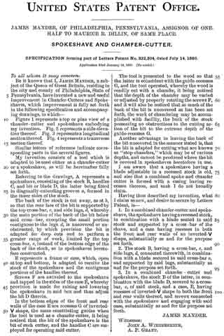
UNITED STATES PATENT OFFICE.
_________________
JAMES MANDER, OF PHILADELPHIA, PENNSYLVANIA, ASSIGNOR OF
ONE-HALF TO MAURICE R. DILLIN, OF SAME PLACE.
SPOKESHAVE AND CHAMFER-CUTTER.
_________________
SPECIFICATION forming part of Letters Patent No. 322,304, dated July 14, 1885.
Application filed January 24, 1885. (No model.)
_________________
To all whom it may concern:
Be it known that I, JAMES MANDER, a subject of the Queen of Great Britain, residing in the city and county of Philadelphia, State of Pennsylvania, have invented a new and useful Improvement in Chamfer-Cutters and Spoke-shaves, which improvement is fully set forth in the following specification and accompanying drawings, in which —
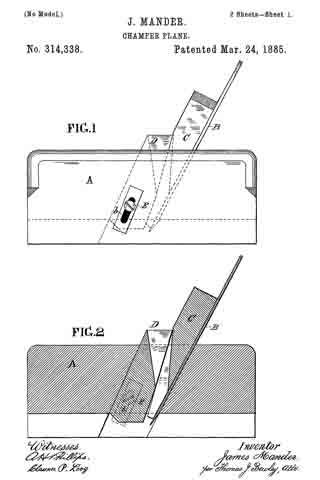
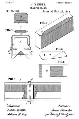
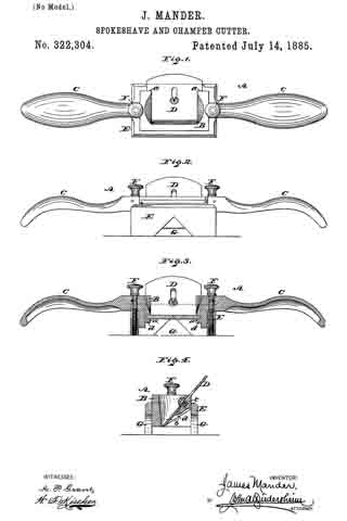
Figure 1 represents a top or plan view of a chamfer-cutter and spokeshave embodying my invention. Fig. 2 represents a side elevation thereof. Fig. 3 represents a longitudinal section thereof. Fig. 4. represents a transverse section thereof.
Similar letters of reference indicate corresponding parts in the several figures.
My invention consists of a tool which is adapted to be used either as a chamfer-cutter or a spokeshave, as will be hereinafter fully set forth.
Referring to the drawings, A represents a spokeshave, consisting of the stock B, handles C, and bit or blade D, the latter being fitted in diagonally-extending grooves a, formed in the inner sides of the stock.
The back of the stock is cut away, as at b, so that the rear face of the bit is supported by the top cross-bar, c, and side lugs, d, whereby the main portion of the back of the bit below said cross-bar, excepting the small portion contiguous to the lugs d, is uncovered or unobstructed, by which provision the bit is adapted for deep cuts and to perform a greater range of work, limited by the top cross-bar, c, instead of the bottom edge of the back of the stock, as in spokeshaves heretofore constructed.
E represents a frame or case, which, open at top and bottom, is adapted to receive the stock of the spokeshave and the contiguous portions of the handles thereof.
Screws F are swiveled to the spokeshave and tapped in the sides of the case E, whereby provision is made for raising and lowering the spokeshave in said box and thus adjust the bit D therein.
In the bottom edges of the front and rear walls of the case E are recesses G of inverted-V shape, the same constituting guides when the tool is used as a chamfer-cutter, it being noticed that the bit of the spokeshave is the bit of such cutter, and the handles C are employed for operating said cutter.
The tool is presented to the wood so that the latter is coincident with the guide-recesses G, and the tool operated, whereby the wood is readily cut with a chamfer, it being noticed that the depth of the chamfer may be varied or adjusted by properly rotating the screws F, and it will also be noticed that as much of the back of the bit is uncovered as has been set forth, the work of chamfering may be accomplished with facility, the back of the stock presenting no obstructions to the cutting action of the bit to the extreme depth of the guide-recesses G.
Another advantage in leaving the back of the bit uncovered in the manner stated is, that the bit is adapted for cutting what are known as “stop-chamfers,” which may be of various depths, and cannot be produced where the bit is covered in spokeshaves heretofore in use.
I am aware that a spokeshave having a blade adjustable in a recessed stock is old, and also that a combined spoke and chamfer cutter is formed with a casing having recesses thereon, and such I do not broadly claim.
Having thus described my invention, what I claim as new, and desire to secure by Letters Patent, is —
1. In a combined chamfer-cutter and spoke-shave, the spokeshave having a recessed stock, in combination with a blade seated in said stock and supported by a cross-bar of the shave, and a case having recesses in both the front and rear walls of an inverted-V shape, substantially as and for the purpose set forth.
2. The stock B, having a cross-bar, c, and side lugs, d, connected therewith, in combination with a blade secured to said cross-bar c, and supported by said lugs, substantially as and for the purpose set forth.
3. In a combined chamfer-cutter and spokeshave, the stock B of the latter, in combination with the blade D, secured to a cross-bar, c, of said stock, and a case, E, having recesses of inverted-V shape in both the front and rear walls thereof, and screws connected with the spokeshave and engaging with said case, substantially as and for the purpose set forth.
JAMES MANDER.
Witnesses:
JOHN A. WIEDERSHEIM,
A. P. GRANT.