No. 1,325,101 – Carriage-Maker’s Plane (Thomas A. Masters) (1919)
[paiddownloads id=”723″]1325101


UNITED STATES PATENT OFFICE.

_________________

THOMAS A. MASTERS, OF BINGHAM CANYON, UTAH.

CARRIAGE-MAKER’S PLANE.

_________________

1,325,101. Specification of Letters Patent. Patented Dec. 16, 1919.
Application filed April 3, 1919. Serial No. 287,291.

_________________

To all whom it may concern:

Be it known that I, THOMAS A. MASTERS, a citizen of the United States, residing at Bingham Canyon, in the county of Salt Lake and State of Utah, have invented certain new and useful Improvements in Carriage-Makers’ Planes, of which the following is a specification.

My invention relates to planes, and has particular reference to improvements in a carriage maker’s rabbet plane.

An important object of the invention is to provide means for preventing the shavings from sticking within the mouth of the plane, and clogging the same, such means being adapted to either raise the shavings and facilitate their discharge from the machine or cut or break the shavings thereby rendering them easy to discharge.

A further object of the invention is to provide a device of the above-mentioned character, which is simple in construction, cheap to manufacture and convenient to use.

Other objects and advantages of the invention will be apparent during the course of the following description.

In the accompanying drawings forming a part of this specification and in which like numerals are employed to designate like parts throughout the same;

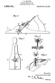
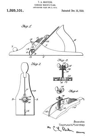
Figure 1 is a side elevation of a plane having my device applied thereto;

Fig. 2 is a side elevation of the clamping plate, having my attachment applied thereto;

Fig. 3 is a transverse sectional view, taken on line 3–3 of Fig. 2; and Fig. a is a perspective view of the attachment embodying my invention, parts being separated.

In the drawings, wherein for the purpose of illustration is shown a preferred embodiment of my invention, the numeral 5 designates the stock or body portion of a carriage maker’s rabbet plane, having the usual handle 6, secured to the rear end thereof, and knob 7 to the forward end. The stock 5 includes upstanding sides or flanges 7. Formed through the stock 5 is a transverse mouth 8, extending through the lower edge of the stock and through the opposite sides thereof. The numeral 9 designates the cutter blade of the plane, which extends for substantially the entire width of the stock 5 and mouth 8, thereby causing the shavings to stick within the mouth clogging the plane. The numeral 10 designates the usual clamping or adjusting plate carried by the stock 7 for locking the blade 9 in adjustment at the desired position.

My attachment comprises a blade 11, arranged upon edge and contacting with the plate 10. The blade 11 extends longitudinally of the plate 10 and has its lower end tapered, the same being provided with a rounded cutting edge 12. The lower end of the plate 10 projects into the mouth 8 and is positioned near the cutting edge 13 of the blade 9. The blade 11 is held in place by means of a bolt 14, having a longitudinal slot 15 receiving the blade 11. At its inner end the bolt 14 has a transverse head 16, held within a recess 17 formed upon the lower side of the plate 10. The upper end of the bolt 14 is screw threaded to receive a winged nut 18, contacting with a washer 19 arranged to engage the blade 11. By this means the blade 11 may be securely locked in place in clamping engagement with the plate 10.

The plane is used in the ordinary manner, and the shavings pass into the mouth 8, contact with the blade 11, and may be raised, thereby facilitating their discharge from the plane. The shavings which are not thus raised are split or broken up by the blade 11, whereby they freely discharge from the plane.

It is to be understood that the form of my invention herewith shown and described is to be taken as the preferred example of the same, and that various changes in the shape, size, and arrangement of parts may be resorted to without departing from the spirit of my invention or the scope of the subjoined claims.

Having thus described my invention, I claim :–

1. The combination with a bench plane, of a thin blade arranged transversely to and intermediate the width of the plane-bit and having its forward end sloping upwardly and rearwardly from the plane of said bit to raise or deflect the chips, and means for detachably mounting said blade.

2. The combination with a bench plane-bit, a thin blade arranged transversely and intermediate the width of the plane-bit, and having its forward edge sharpened to split the chip, and means for detachably mounting said blade.

3. The combination with the bench plane bit, of a thin blade arranged traversely of and intermediate the width of said bit, and having its forward edge sloped upwardly and rearwardly from the front of said bit, and sharpened to raise or deflect and split the chip and means for detachably securing the blade to the said bit.

In testimony whereof I affix my signature in presence of two wltnesses.

THOMAS A. MASTERS.

Witnesses:
J. L. HUCHEL, D. D. S.,
JESS. ZABRISPIE.

No. 1,249,674 – Plane-Spur (Edmund A. Schade) (1917)

[paiddownloads id=”719″]1249674


UNITED STATES PATENT OFFICE.

_________________

EDMUND A. SCHADE, OF NEW BRITAIN, CONNECTICUT, ASSIGNOR TO THE STANLEY RULE & LEVEL CO.,
OF NEW BRITAIN, CONNECTICUT, A CORPORATION OF CONNECTICUT.

PLANE-SPUR.

_________________

1,249,674. Specification of Letters Patent. Patented Dec. 11. 1917.
Application filed June 18, 1917. Serial No. 175,271.

_________________

To all whom it may concern:

Be it known that l, EDMUND A. SCHADE, a citizen of the United States of America, residing at New Britain, Connecticut, have invented a new and nuseful Plane-Spur, or which the following is a specification.

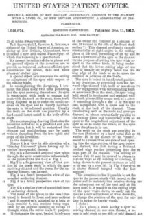
My present invention relates to planes and the general objects of the invention are to provide an improved and more efficient spur construction for rabbet, dado and other planes or similar type.

A special object is to rnaintain the setting or adjustment or the spar with respect to the cutting blade.

ln accomplishing the foregoing, I construct the plane stock with teeth projecting into the spur receiving channel and the spur is constructed with teeth to engage and mesh with the teeth on the stock, these teeth being disposed so as to resist the strain exerted on the spur and to thereby rnaintain the spur in its adjusted position. Usually the teeth on the steel are provided hy a hard metal insert seated in the body out the stock.

The accompanying drawing illustrates the invention embodied in a practical and preferred form, but it will be understood that changes and modifications may be made without departing from the true spirit and scope of the invention.

ln the drawing:

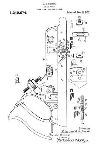
Figure 1 is a view in side elevation of a “Stanley Universal” plane having rny invention incorporated therein.

Fig. 2 is a horizontal sectional view taken through the spar construction substantially on the plane of the line 2–2 of Fig. 1.

Fig 3 is a fragmentary view of that portion of the plane stock in which the spur receiving channel and the recess for the anchoring element are formed.

Fig. 4 is a detail perspective view or the so-called anchoring element.

Fig, 5 is a detail perspective view of the spur.

Fig. 6 is a similar view of a modfied form of anchoring element.

The stock or the plane in the case illustrated is formed in front and rear sections 7 and 8 respectively, attached to a back or body member 9, said sections being separated by an angular opening or throat 10 through which the cutter blade 11 projects.

12 designates the spur, located in advance of the cutter and disposed in a channel or seat 13 formed in the side of the front stock section 7. This channel preferably extends substantially at right angles to the cutting plane of the tool, permitting of an up and down adjustment or the spur in the channel for the purpose of setting the spur with respect to the cutter blade, it being understood that the lower cuttiing edge of the spur is usually set slightly below the cutting edge or the blade so as to score the material in advance of the blade.

The spur is locked in its adjusted position in my invention, by providing it on the forward edge thereof with teeth or serrations 14 for engagement with corresponding teeth or serrations 15 on the stock, the spur being held seated in its channel and engaged with the teeth aforesaid by rneans such as a screw 16 extending through a slot 17 in the spur into engagement with a screw seat in the stock at the back or the channel. These interlocking teeth on the stock and spur are disposed in planes substantially parallel to the cutting plane and transversely with respect to the longitudinal adjustment of the spur so as to resist the strain on the spur when the plane is in use.

The teeth on the stock are provicled in the case illustrated by a hard metal disk or washer 18 in the nature of an “insert”, seated in a recess 19 at one side of and opening into the edge portion of the spur receiving channel, this disk having a flattened toothed edge portion projection into the edge part of the channel. The locking or anchor disk 18 may be secured in planes in various ways as by welding or riveting, it being shown in the present instance as held in its seat by a rivet 20. ln Fig. 6 the rivet is shown formed integral with the disk rnember.

This invention rnakes it possible to set the spur to the proper depth with respect to the cutter and to maintain that relation during the subsequent use of the tool and at the same time, it is possible as the cutting edge of the spur wears down, to easily set the spur to at new adjustment or when desirable, to change the position of the spur for cutting in softer or harder woods.

l claim :

1. ln a plane, a stock having a spur receiving channel in one side thereof, a recess in said stock at one side of said channel and opening into the edge of said channel, a hard metal locking device fixed in said recess and having a toothed edge at one side projecting into the side edge of the channel aforesaid, a spur having one edge toothed to coact with the teeth on said locking portion, the width of said spur corresponding to the width of said channel, said spur being adjustably engaged with said locking device by a lateral movement of said spur whereby the degree of projection of said spur below said stock may be controlled, and means for holding said spur against lateral disengagement from said locking device when the latter is in its adjusted operative position.

2. In a plane, a stock having a spur receiving channel in one side thereof, a recess in said stock at one side of said channel and opening into the edge of said channel, a hard metal locking device fixed in said recess and having a toothed edge at one side projecting into the side edge of the channel aforesaid, a spur having one edge toothed to coact with the teeth on said locking portion, the width of said spur corresponding to the width of said channel, said spur being adjustably engaged with said locking device by a lateral movement of said spur whereby the degree of projection of said spur below said stock may be controlled, and means for holding said spur against lateral disengagement from said locking device when the latter is in its adjusted operative position, said holding means comprising a screw passing through a longitudinal slot in said spur and screwing into said stock.

EDMUND A. SCHADE.

_________________

Copies of this patent may be obtained for five cents each, by addressing the “Commissioner of Patents, Washington, D. C.”
_________________

No. 1,112,399 – Bench Plane (Harvey M. Wood) (1914)

[paiddownloads id=”700″]1112399


UNITED STATES PATENT OFFICE.

_________________

HARVEY M. WOOD, OF LOS ANGELES, CALIFORNIA.

BENCH-PLANE.

_________________

1,112,399. Specification of Letters Patent. Patented Sept. 29, 1914.
Original application filed November 8, 1907. Serial No. 401,341. Divided and this application filed October
14, 1912. Serial No. 725,577.

_________________

To all whom it may concern:

Be it known that I, HARVEY M. WOOD, a citizen of the United States, residing at Los Angeles, in the county of Los Angeles and State of California, have invented a new and useful Bench-Plane, of which the following is a specification.

The object of this invention is to protect the cutting edge of the blade during the backward stroke of the plane and while standing idle on its sole, this result being attained by use of a heel-piece yieldingly projecting through and beyond the sole and serving to normally uphold the same above the table top.

This application is a division of my co-pending application for patent on bench plane, Serial No. 401,341, filed Nov. 8, 1907.

The accompanying drawings illustrate the invention.

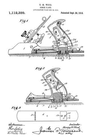
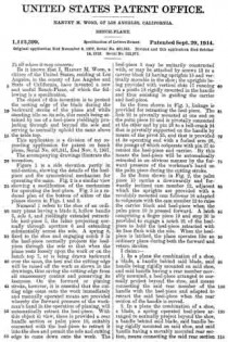
Figure 1 is a side elevation partly in mid-section, showing the details of the heel-piece and the symmetrical mechanism for operating the same. Fig. 2 is a similar view showing a modification of the mechanism for operating the heel-piece. Fig. 3 is a reduced plan of the bottom of either of the planes shown in Figs. 1 and 2.

Numeral 1 refers to the shoe of an ordinary plane having a blade 2, hollow handle 3, sole 4, and yieldingly extended retractible heel-piece 5, the latter projecting normally through aperture 6 and extending substantially across the sole. A spring 8, fixed to the shoe and engaging notch 9 in the heel-piece normally projects the heel-piece through the sole so that when the plane rests loosely upon the work or on the bench top 7, or is being drawn backward over the same, the heel and the cutting edge will be raised off the work as shown in the drawings, thus saving the cutting edge from all unnecessary contact and preserving its keenness. On the forward or planing stroke, however, it is essential that the cutting edge come onto the work immediately and manually operated means are provided whereby the forward pressure of the workman’s hand in the operation of planing, will automatically retract the heel-piece. With this object in view, there is provided a rear handle section or palm piece 10, suitably connected with the heel-piece to retract it into the shoe and permit the sole and cutting edge to come down onto the work. The heel-piece 5 may be unitarily constructed with, or may be attached by screws 13 to a carrier block 14 having uprights 15 and vertically movable in the shoe; the uprights being provided with vertical slots 17 running on a pintle 18 rigidly mounted in the handle and thus assisting in guiding the carrier and heel-piece.

In the form shown in Fig. 1, linkage is provided for retracting the heel-piece. The link 22 is pivotally mounted at one end on the palm piece 10 and is pivotally connected at the other end by pin 23 to a bell-crank 24 that is pivotally supported on the handle by means of the pivot 25, and that is provided at its operating end with a forked arm 26, the prongs of which cooperate with pin 27 to retract the heel-piece and carrier. By this means the heel-piece will be automatically retracted in an obvious manner by the forward pressure of the workman’s hand on the palm piece during the cutting stroke.

In the form shown in Fig. 2, the palm piece 10 carries a downwardly and forwardly inclined cam member 12, adjacent which the uprights are provided with a revolubly mounted cam follower 16 adapted to cooperate with the cam member 12 to raise the carrier block and heel-piece when the palm piece 10 is pressed forward. A latch comprising a finger piece 19 and stop 20 is provided to engage a notch 21 of the heel-piece to hold the heel-piece retracted with its face flush with the sole. When the heel-piece is latched, the plane operates like an ordinary plane during both the forward and return strokes.

I claim :–

1. In a plane the combination of a shoe, a blade, a handle behind said blade, said handle being rigidly mounted on said shoe, and said handle having a rear member movably mounted, a heel-piece arranged to normally project beyond the shoe, and means connecting the said rear member of the handle with the heel-piece and adapted to retract the said heel-piece when the rear section of the handle is moved.

2. In a plane the combination of a shoe, a blade, a spring operated heel-piece arranged to normally project beyond the shoe, a handle behind said blade, said handle being rigidly mounted on said shoe, and said handle having a movably mounted rear section, means connecting the said rear section of the handle with the heel-piece and adapted to retract the said heel-piece when the rear section of the handle is moved, and means for holding said heel-piece in its retracted position.

3. In a plane, the combination of a shoe, a blade, a hollow handle having a rear section pivotally mounted, a spring-operated heel-piece adapted to normally project beyond the shoe and mechanism in the hollow of the handle connecting the rear section of the handle with the heel-piece and adapted to retract the heelfpiece when the rear sec-
tion of the handle is moved.

4. In a plane the combination of a shoe, a blade, a hollow handle having a rear section pivotally mounted, a spring operated heel-piece adapted to normally project beyond the shoe, and link mechanism supported in the hollow of the handle and connecting the rear section of the handle with the heel-piece and adapted to retract the heel-piece when the rear section of the handle is moved.

5. In a plane the combination of a shoe, a blade, a hollow handle having a rear section pivotally mounted, a carrier riding in the hollow of the handle, a heel-piece mounted on the carrier and adapted to normally project through and beyond the shoe, and means in the hollow of the handle connecting the rear section of the handle with the carrier and adapted to retract the carrier and heel-piece by motion of the rear section of the handle.

6. In a plane the combination of a shoe, having a sole, a blade, a hollow handle having a rear section pivotally mounted, a heel-piece adapted to normally project beyond the sole, a bell-crank mounted within the handle and having a forked arm, a link connecting one arm of the bell-crank with the rear section of the handle, and a pin mounted on the heel-piece and cooperating with the forked arm of the bell-crank to be raised by the same.

7. In a plane, the combination with a shoe, a blade and a handle behind said blade, of a spring-operated heel-piece carried by said handle and arranged to lift the heel of the plane, and manually operated means for retracting said heel-piece.

8. In a plane, the combination with a shoe, a blade and a handle behind said blade, of a spring-operated heel-piece carried by said handle and arranged to lift the heel of the plane, means for retracting said heel-piece, and means for holding said heel-piece in its retracted position.

9. A plane comprising a sole, a handle fixed to said sole and provided with a movable palm-piece, and a heel piece operatably connected to the palm-piece and normally below the plane of the sole and adapted to be raised by movement of said palm-piece.

In testimony whereof, I have hereunto set my hand at Los Angeles, California, this 28th day of September 1912.

HARVEY M. WOOD.

In presence of —
JAMES R. TOWNSEND,
ROBERT A. STEPS.

_________________

Copies of this patent may be obtained for five cents each, by addressing the “Commissioner of Patents, Washington, D. C.”
_________________

No. 1,085,651 – Guard For Hand-Planes (John E. Westberg) (1914)

[paiddownloads id=”693″]1085651


UNITED STATES PATENT OFFICE.

_________________

JOHN E. WESTBERG, OF EL CAMPO, TEXAS.

GUARD FOR HAND-PLANES.

_________________

1,085,651. Specification of Letters Patent. Patented Feb. 3, 1914.
Application filed November 27, 1911. Serial No. 662,640.

_________________

To all whom it may concern:

Be it known that I, JOHN E. WESTBERG, a citizen of the United States, residing at El Campo, in the county of Wharton, State of Texas, have invented certain new and useful Improvements in Guards for Hand-Planes; and I do hereby declare the following to be a full, clear, and exact description of the invention, such as will enable others skilled in the art to which it appertains to make and use the same.

This invention relates to improvements in bench planes.

The principal object of the invention is to provide a guard for bench planes which will prevent the shavings or splinters from contacting with and injuring the hand of the operator.

Another object of the invention is to provide a guard for the purpose described which is in the nature of an attachment and which can therefore be readily applied to any plane now in common use which includes the usual front handle.

A further object of the invention is to provide a guard attachment for the purpose described, which is formed from a single blank of metal, is therefore simple in construction, and is cheap to manufacture.

With these and other objects in view, the invention consists in the construction and novel combination of parts hereinafter fully described, illustrated in the accompanying drawings, and pointed out in the claim hereto appended; it being understood that various changes in the form, proportion, size and minor details of construction within the scope of the claim, may be resorted to without departing from the spirit or sacrificing any of the advantages of the invention.

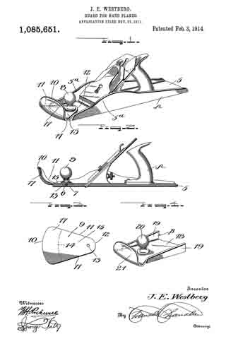
In the drawing Figure 1 is a perspective view of a jack-plane showing my invention associated therewith, Fig. 2 is a longitudinal section through the same, the handle being shown in elevation, Fig. 3 is a plan view of the blank from which the guard attachment is formed, and Fig. 4 is a detail perspective view of the forward end of a jack-plane showing a modified form of my invention.

Like reference numerals designate corresponding parts in all the figures of the drawing.

Referring to the drawing, a bench plane is indicated as a whole by the reference character A. This plane includes the usual body or base 5 having a threaded recess 6 formed centrally in its forward end for the reception of a screw 7 carried by the usual knob or forward handle 8.

The preferred form of my invention, as illustrated in Figs. 1 to 3 inclusive, consists of a guard formed from a substantially triangular blank 9 of metal. This blank includes a curved base 10 and converging sides 11–11, said sides terminating in an apex 12. Formed in the apex thereof is an opening 13. The end of the blank opposite the opening 13 is transversely bent along the arcuate line la to form a consequent base 15 and an upstanding flange 17, said flange being centrally dished for a purpose hereinafter described. In attaching this guard to a plane, the opening 13 of said guard is placed in registration with the threaded recess 6 of the body 5. It will thus be observed that the body 15 of the guard is of such a length as to project the flange 17 slightly in advance of the front end of the body 5 of the plane. The knob or handle 8 is then secured by means of screws 7 to the body 5, and at the same time clamping the guard 9 against said body 5. It will furthermore be noted that the sides 11–11 of the guard abut against the side walls 5a of the body and thereby prevent any lateral swinging movement of said guard.

In the modification, as illustrated in Fig. 4 of the drawing, the plane B is formed with the usual body or base 18 and side walls 19–19. A front knob or handle 20 is secured in the usual manner to the base 18. The forward end of the base in advance of the handle 20 is bent upwardly to form an arcuate dished guard 21.

From the foregoing, it will be observed that when the plane is in operation, any shavings or splinters which would ordinarily contact with the operator’s hand, will be prevented by means of the guard as above described.

What is claimed is:

The combination with a frame including a body having side flanges and having a centrally disposed blade projecting therefrom, a handle carried by the body and arranged in rear of the blade, a handle carried by the body and arranged in front of the blade, and a guard for said front handle secured to the body by said handle and disposed in advance thereof and intermediate said flanges.

In testimony whereof, I affix my signature, in presence of two witnesses.

JOHN E. WESTBERG.

Witnesses:
J. E. McIVER,
CHAS. BLOOM.

_________________

Copies of this patent may be obtained for five cents each, by addressing the “Commissioner of Patents, Washington, D. C.”
_________________

No. 1,048,455 – Plane (James M. Burdick) (1912)

[paiddownloads id=”686″]1048455


UNITED STATES PATENT OFFICE.

_________________

JAMES M. BURDICK, OF NEW BRITAIN, CONNECTICUT, ASSIGNOR TO THE STANLEY RULE &
LEVEL COMPANY, OF NEW BRITAIN, CONNECTICUT, A CORPORATION OF CONNECTICUT.

PLANE.

_________________

1,048,455. Specification of Letters Patent. Patented Dec. 24, 1912.
Application filed July 11, 1912. Serial No. 708,840.

_________________

To all whom it may concern:

Be it known that I, JAMES M. BURDICK, a citizen of the United States, residing at New Britain, Hartford county, State of Connecticut, have invented certain new and useful Irnprovements in Planes, of winch the following is a full, clear, and exact description.

This invention relates to an improvement in the construction of planes, and is more particularly concerned with the construction of a detachable cap piece for the cutter or “plane iron”. In such cap pieces, it has hitherto been the practice to provide a detachable cap piece provided with means for engaging with the cutter and clamping it in position upon its seat upon the plane body.

My present invention contemplates employing such a cap piece in the form of a main body portion provided with a palm rest and carrying a relatively movable clamping member adapted to be positioned to engage and clamp the cutter on its seat and to lock said cap piece against movement relative to the plane body.

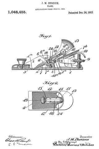
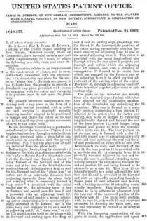
In the drawings illustrating a preferable embodiment of the invention: Figure 1 is a longitudinal section through a standard type of plane equipped with a detachable cap constructed in accordance with the present invention. Fig. 2 is a top plan view of said cap removed from the plane body.

Referring to the drawing by numerals: 1 designates the body of a plane provided with side walls or fianges 2 and a detachable shoe 3 at the forward end thereof, a throat 1a being formed at the forward end of the plane and in the rear of the detachable shoe portion thereof. 4 designates a frog or seat for the forward end of the “plane iron” or cutter, and 5 an interiorly threaded boss projecting upwardly from the plane body and carrying what is commonly termed a “cap screw” 6 provided with the usual headed end 6a. An adjusting lever 10 has its forward end seated over the boss 5 and is provided with an adjusting head 10a. To the rear of said head is a second adjusting device comprising a lever member 8 pivotally mounted at its forward end in the plane body and engaged at its rear end by an adjusting nut 9. A “plane iron” or cutter 7 is seated on the body of the plane with its forward end resting upon the frog or seat 4 and its cutting edge projecting into the throat 1a, the intermediate portions of the cutter resting respectively over the forward ends of the adjusting lever 10 and of the second adjusting lever 8. This cutter is provided with the usual longitudinal slot through which the cap screw 6 projects and through and within which the adjusting head 10a extends, and with a plurality of corrugations 7b formed in its under face which are engaged by the forward end of the adjusting lever 8 to effect vertical adjustment of the cutting edge of the cutter. The lever 10, through its adjusting head 10a, effects lateral or angular adjustment of said cutting edge.

The parts so far described are merely those of a standard type of plane which has been selected for the illustrative application of the detachable cap embodying the invention. This cap is formed as a main body portion comprising a base portion 11 adapted to be seated over the cutter and having side walls or flanges 12 extending longitudinally thereof and beyond the end of the base portion 11, said flanges being widened and joined to form the rounded hollow palm rest 13. The base portion 11, at its rear end, is formed with a slot 11a and with spaced ears 14 extending upwardly from said base portion at the rear end thereof and positioned on either side of said slot. Intermediate its ends, and forward of the ears 14, the base portion 11 is provided with a key-hole slot 15. A clamping lever 16 is pivotally mounted adjacent its rear end between the ears 14, said end extending downwardly between the ears 14 and through the slotted portion 11a and being formed at its extremity as a cam 18. This lever 16 extends forwardly to a point adjacent the key-hole slot 15 and is provided at its forward end with an upwardly extending handle or finger piece 19 and adjacent said handle, with a locking shoulder 20 extending downwardly therefrom. This shoulder is posi-
tioned to lie in substantial alinement with the rear end of the narrowed portion of the key-hole slot 15. The main body portion, with its ears 14, side walls 12 and rearward extension 13 forming the palm rest, may be, and preferably is, formed as an integral structure.

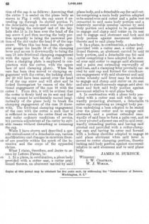
With the foregoing construction of the parts in mind, the application and operation of the cap is as follows: Assuming that the cutter 7 is seated on the plane body as shown in Fig. 1 with the cap screw 6 extending up through its slotted portion 7a, the detachable cap is seated over the cutter by bringing the enlarged end of the key-hole slot 15 in its base over the head of the cap screw 6 and then moving the body portion upwardly to bring the narrowed portion of the slot under the head 6a of the cap-screw. When this has been done, the operator grasps the handle 19 of the clamping lever and moves it downwardly to bring the cam 18 into frictional clamping engagement with the upper face of the cutter 7 (or, when a clamping plate is employed in conjunction with the cutter, with the upper face of said clamping plate). When the cam has been thus moved to clamping engagement with the cutter, the locking shoulder 20 will have been moved over the head 6a of the cap screw and will abut and be locked thereagainst by reason of the frictional engagement of the cam 18 with the cutter 7. From this, it will be evident that the cutter is firmly held on its seat and that the cap cannot be accidentally moved longitudinally of the plane body to break the clamping engagement of the cam 18 therewith. The frictional clamping engagement of the cam with the cutter is such that it is sufficient to retain the cutter fixed on the seat under ordinary conditions of service, but permits adjustment of the cutter by suitable means without disturbing or loosening the cap.

While I have shown and described a specific embodiment of a detachable cap, various modifications and changes in structure thereof are possible within the spirit of the invention and the scope of the appended claims.

What I claim, therefore, and desire to secure by Letters Patent, is:

1. In a plane, in combination, a plane body provided with a cutter seat, a cutter positioned thereon, an abutment carried by said plane body, and a detachable cap for said cutter comprising a main body portion adapted to be seated over said cutter and a palm rest connected to said main body portion and a relatively movable member carried by said body portion and adapted to be positioned to engage and clamp said cutter on its seat and to engage said abutment and lock said body portion against movement relative thereto and to said plane body.

2. In a plane, in combination, a plane body provided with a cutter seat, a cutter positioned thereon, an abutment carried by said body portion, and a detachable cap for said cutter comprising a base adapted to be seated over said cutter to engage said abutment and a paim rest extending rearwardly of said base, and a clamping lever pivotally carried by said cap and formed for simultaneous engagement with said abutment and said cutter whereby said lever may be actuated to engage and clamp said cutter on its seat and also to simultaneously engage said abutment and lock said body portion against movement relative to said plane body.

3. In combination with a plane body provided with a cutter seat and with an upwardly projecting abutment, a detachable cutter cap comprising an integral body portion embodying a base adapted to be seated over the plane cutter and to engage said abutment, and a portion extended rearwardly of said base to form a palm rest, and a lever pivoted adjacent one end to said rearwardly extending portion and having said pivoted end provided with a cutter-clamping cam and having its outer end formed with a locking shoulder adapted to engage said plane abutment when said lever is moved to cutter clamping position, thereby locking said body portion against movement relative to said abutment and to said plane body.

JAMES M. BURDICK.

Witnesses:
I. W. CHAPMAN,
W. J. WORAM.

_________________

Copies of this patent may be obtained for five cents each, by addressing the “Commissioner of Patents, Washington, D. C.”
_________________

Corrections in Letters Patent No.1,048,455.


It is hereby certified that in Letters Patent No. 1,0143,455, granted December 24, 1912, upon the application of James M. Burdick, of New Britain, Connecticut, for an improvement in “Planes,” an error appears in the printed specification requiring correction as follows: Page 2, line 50, after the word “cutter” insert the words to engage said abutment; and that the said Letters Patent should be read with this correction therein that the same may conform to the record of the case in the Patent Office.

Signed and sealed this 28th day of January, A. D., 1913.
[SEAL]

C. C. BILLINGS,
Acting Commissioner of Patents.

No. 930,243 – Handle Construction For Planes And Other Tools (Charles B. Stanley) (1909)

No. 930,243 – Handle Construction For Planes And Other Tools (Charles B. Stanley) (1909)

[paiddownloads id=”663″]930243


UNITED STATES PATENT OFFICE.

_________________

CHARLES B. STANLEY, OF NEW BRITAIN, CONNECTICUT, ASSIGN OR TO THE STANLEY RULE
& LEVEL COMPANY, OF NEW BRITAIN, CONNECTICUT, A CORPORATION OF CONNECTICUT.

HANDLE CONSTRUCTION FOR PLANES AND OTHER TOOLS.

_________________

930,243. Specification of Letters Patent. Patented Aug. 3, 1909.
Application filed May 8, 1909. Serial No. 494,909.

_________________

To all whom it may concern:

Be it known that I, CHARLES B. STANLEY, a citizen of the United States, residing at New Britain, county of Hartford, State of Comecticut, have invented certain new and useful Improvements in Handle Construction for Planes and other Tools, of which the following is a full, clear, and exact description.

My invention relates to a new and improved tool handle particularly adapted to planes.

The object of the invention is to provide a superior construction by which a strong and durable handle may be formed from composition which would otherwise lack sufficient strength in itself to resist hard usage. Ordinarily this material is molded from some suitalble composition, and it has been found that by reason of the fragile character of most compositions there is great loss due to breakage, not only occurring when the handles are applied to the planes, but also in after use. By my invention the strain of the holding devices is effectively resisted, the molded or pressed composition of the handle being relieved of the same.

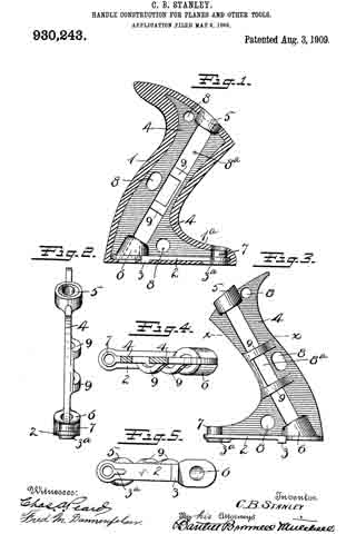
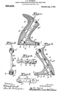
In the accompanying drawings Figure 1 is a vertical section of a plane handle constructed to embody my invention, a portion of the same being shown in side elevation. Fig. 2 is an edge view of reinforcing means detached from the handle. Fig. 3 illustrates the same part and the reverse side from that shown in Fig. 1. Fig. 4 is a section on line x–x of Fig. 3, looking down. Fig. 5 is a view of the under side of the same part.

In the drawings, 1 represents the grip portion of the handle, which may be of conventional form, said grip portion being made of a suitable composition material molded or pressed to the desired configuration. Arranged within the handle is a reinforcement of iron, or other suitable material, capable of withstanding severe strains and hard usage. This reinforcement is preferably of skeleton form and is so arranged as to furnish a backbone for the handle at all vulnerable points, and at the same time is available to receive the screw fastenings (not shown), by which said handles are secured to the plane bodies. This reinforcement comprises the base plate 2, preferably provided with the feet 3–3a, the ends of which feet are coincident with the bottom surface of the finished handle so as to act as a support. The plate 2 has an upwardly extending fin 4, which extends through the grip portion 1 of the handle and well toward the upper end thereof, as best seen in Fig. 1.

5 is an upper bearing for one of the fastening screws (not shown). 6 is a lower bearing for the same screw. The upper bearing 5 is coincident with the upper end of the grip portion of the handle, so that the strain of the screw head when in place will be taken directly by the bearing 5, then by the web 4, then by plate 2, and finally by the bearing 6 and foot 3. 7 is another bearing for another fastening screw, the upper end of this bearing being exposed at the upper surface of a forwardly extending portion 1b at the base of the grip 1. This bearing 7 likewise takes the strain of the head of the second screw, which passes therethrough when the handle is applied.

The web 4, in order to insure lightness may be out away, as at 8–8a, the cut-away portion so being between the bearings 5–6. The two sides of the web adjacent the cut-away portion 8a may have offset connections 9–9 to properly tie together the two parts of the web, said connections being offset to afford clearance passage for the screw. These openings 8–8a permit the composition material to become more rigidly anchored to the reinforcement.

From the foregoing it will be seen that a handle thus constructed possesses very great strength and durability, and the danger of breakage is reduced to a minimum. It will be also seen that the strain of the holding screws is taken wholly by such parts and material as are best capable of withstanding the same. It will also be seen that the composition covering or envelop may be made from a material that would otherwise be unavailable because of too little initial strength, such, for example, as cork. These and other advantages will be apparent to the experienced mechanic.

What I claim is:

1. In a tool handle, a grip of composition material, an interior reinforcement having a screw passage therethrough from end to end of the grip portion of said handle, said reinforcement carrying a bearing at the upper and lower end to receive a fastening screw.

2. In a tool handle, a grip of composition material, an interior reinforcement having a screw passage therethrough from end to end of the grip portion of said handle, said reinforcement having a bearing at each end to receive a fastening screw, and having a second screw passage, and a bearing for a second fastening screw, both of said bearings relieving the composition covering of said reinforcernent from the strain of fastening screws.

3. A tool handle formed of composition material and having an inclosed metallic reinforcement, said reinforcernent having two screw passages therein and having bearings at the base of the reinforcement adjacent to said screw passages, and other bearings at the upper end of both screw passages arranged to directly receive the strain of fastening screws.

CHARLES B. STANLEY.

Witnesses:
ROBERT N. PECK,
W. J. WORAM.

No. 928,227 – Tool-Handle (Charles B. Stanley) (1909)

[paiddownloads id=”662″]928227


UNITED STATES PATENT OFFICE.

_________________

CHARLES B. STANLEY, OF NEW BRITAIN, CONNECTICUT, ASSIGNOR TO THE STANLEY RULE
& LEVEL COMPANY, OF MERIDEN, CONNECTICUT, A CORPORATION OF CONNECTICUT.

TOOL-HANDLE.

_________________

928,227. Specification of Letters Patent. Patented July 13, 1909.
Application filed February 20, 1909. Serial No. 479,081.

_________________

To all whom it may concern:

Be it known that I, CHARLES B. STANLEY, a citizen of the United States, residing at New Britain, county of Hartford, State of Connecticut, have invented certain new and useful Improvements in Tool-Handles, of which the following is a full, clear, and exact description.

My invention relates to new improvements in tool handles and is particularly useful for plane handles.

The object of the invention is to provide an improved combination of parts whereby composition and similar handles may be constructed in such a way as to effectively withstand the strain which comes upon the fastening screw at the forward portion of the handle, thereby removing the danger of breakage, which has been found to be in this class of handles, very great.

In the manufacture of what are known as imitation rubber handles, the composition material employed is of a fibrous or brittle nature, and it frequently happens, owing to the shape of the handle, that the material through which the forward screw passes is unequal to the strain and that portion of the handle becomes broken.

With my invention I propose to overcome this defect and to provide the handle at its most vulnerable point with an effective reinforcing device which can be very economically produced, and in combination with the remainder of the handle, be used to great advantage.

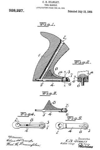
In the accompanying drawings, — Figure 1 is a vertical section of a handle for a plane, the reinforcement therefor being shown in side elevation. Fig. 2 is a section on the line X–X Fig. 1. Fig. 3 is a side elevation of the reinforcement, detached. Fig. 4 is a plan view thereof. Fig. 5 is a view of the under side thereof.

1 represents the body or grip portion of the composition plane handle, usually made from fibrous material of considerable brittleness, molded to the desired shape. The handle is usually screwed to the upper side of the sole of the plane (not shown) by means of suitable fastening devices passing through the apertures 2 and 3. Inasmuch as the aperture 3 is located in a comparatively thin part of the extended base 1a of the handle, the pressure employed in screwing the handle in place is frequently such as to break the handle. Then, too, the strain which comes upon the forward end of the handle, when held by the operator, is very great, owing to the weight of the plane, which is largely borne by that end. Also, the inclination of the large screw which enters the aperture 2 is such as to cause the handle to be forced backward in attaching it to the plane, thereby creating what is known as the drag of the screw. This drag of the screw causes the handle to move backward relatively to the plane sole, to which it is attached, and when the material is fibrous or brittle, causes the material to be broken adjacent to the forward screw. To overcome this defect I provide metallic means for reinforcing the lower part of the handle, taking the strain of the screws and relieving the handle from all tendency to breakage, the reinforcing means in the particular form shown herein comprising the plate 4, having the feet 5–6.

7 is a hub extending upward from the plate 4 and directly over the circular part of the foot 6. The screw hole, or passage 3, extends through the hub 7 and the foot 6. The screw passage 2, extends through the rear end of the plate 4, preferably closely adjacent to the foot 5, which, in this particular instance, is located just forward of said screw passage.

8 is a reinforcing web formed on the upper side of plate A to prevent the buckling or breaking of the base plate and to establish in general a secure and operative connection between the base plate and the remainder of the handle.

It should be understood that although the feet 5 and 6 perform a useful function, their use is preferable rather than essential, as the base plate 4 would in large measure discharge the duties required of it if the feet were removed and it rested directly upon the upper side of the sole of the plane.

It should be understood also that the shape of the reinforcing web where it extends up into the gripping portion of the handle, is not material. The height to which it extends, and the shape which it takes in the portion of the handle which is grasped by the hand, is a matter which may be greatly varied without departing from the spirit or true character of my invention.

In operation it will be seen that the strain which in use is occasioned by the screw passing through the passage 2, is taken by the portion of the metallic plate surrounding the screw, so that all danger of breaking off the handle at its base is avoided. Likewise, the strain, which, but for the metallic reinforcement, would come upon the extended front end of the handle when in use, is prevented from breaking the handle or doing damage in any way.

It will be understood that the head of the screw which extends through the passage 3, sets down upon the metallic hub 7 and that the pressure of the screw is transinitted directly downward to the base of the plane, the connection between the underside of the screw head and the sole of the plane being metallic all the way.

The strain occasioned by the drag upon the screw, inserted through the passage is taken by the metal surrounding the passage, thereby reducing all danger of breakage to a minimum.

The material of the handle being usually molded into shape permits the plate 4 and the parts connected therewith to be located within and hidden by the material of the handle, the only exposed parts being in the preferred form — the feet 5 and 6 and the upper end of the hub 7, which latter, when the screw is in place in the passage 3, is covered by the head thereof. By this means the strain of the holding screws is wholly taken up by the metallic portion of the plane handle, and the plane handle as a whole becomes as effectively provided with means for resisting tendencies to breakage as if it were not composed of a composition or other brittle material.

It should be stated that this invention is not confined to imitation rubber handles but extends to other handles produced by shaping in a mold and reinforced in the manner herein described.

It should also be understood that it is immaterial whether the reinforcing plate and its subordinate parts are composed of a single piece of cast metal or are made in separate parts and united together in any well understood mechanical manner.

What I claim is:

1. In a composition handle of the character described, a grip portion and a base portion, a plate reinforcement for said base embedded therein, said base having a screw passage extending through said plate, said reinforcement being arranged to take the strain of the screw and distribute the same along the base to relieve the material of the handle from said strain.

2. In a tool handle, a composition body molded to the form of the handle and comprising a grip portion and a base portion, a plate reinforcement for said base, said plate being embedded therein and having a foot projecting downwardly and terminating coincident with the lower bearing surface of the base portion, a screw passage adjacent to said foot, said reinforcement being arranged to take the strain of the screw to relieve the material of the handle from said strain.

3. In a composition tool handle of the character described, a base, a plate-like reinforcement embedded therein, a web reinforcement for said plate, said web being formed integrally therewith.

4. In a composition handle of the character described, a grip portion and a base portion, a metallic plate reinforcement for said base, two screw passages through said handle and plate, portions of said plate being arranged coincident with the lower surface of the base of the handle.

5. In a tool handle of the character described, a grip portion, a base extending forwardly from the lower end of said grip portion, a plate reinforcement for said base and having two screw passages, one coincident with the grip portion, and the other coincident with the forwardly extending base portion, a part of said plate being coincident with the lower surface of the base.

6. In a tool handle of the character described a grip portion, a base extending forwardly from the lower end of said grip portion, a plate reinforcement for said base and having two screw passages, one coincident with the grip portion, and the other coincident with the forwardly extending base portion, a part of said plate being coincident with the lower surface of the base, a hub on the plate surrounding the screw passage coincident with the forward rear extension of the base and arranged to directly receive the strain of the screw.

CHARLES B. STANLEY.

Witnesses:
W. J. WORAM,
H. S. WALTER.

No. 890,519 – Joining-Plane (Wilfred R. Lansberry) (1908)

[paiddownloads id=”654″]890519


UNITED STATES PATENT OFFICE.

_________________

WILFRED R. LANSBERRY, OF DES MOINES, IOWA.

JOINING-PLANE.

_________________

890,519. Specification of Letters Patent. Patented June 9, 1908.
Application filed September 19, 1907. Serial No. 393,734.

_________________

To all whom it may concern:

Be it known that I, WILFRED R. LANSBERRY, a citizen of the United States, residing at Des Moines, in the county of Polk and State of lowa, have invented a certain new and useful Joining-Plane, of which the following is a specification.

The object of my invention is to provide a plane especially designed for use in trimming or cutting away the edge of a board on a line exactly parallel with the edge of another board placed adjacent to it, so that said boards may be fitted together accurately and smoothly, and my device is of special advantage in cases where neither of the boards to be fitted have perfectly smooth straight edges, and where it is necessary to do the work by hand.

My invention consists in the construction of the joining plane, whereby the objects contemplated are attained, as hereinafter more fully set forth, pointed out in my claims and illustrated in the accompanying drawings, in which —

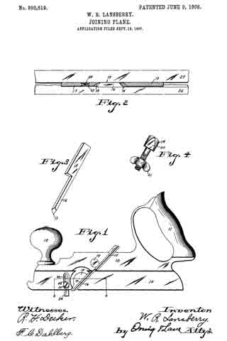
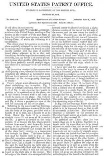
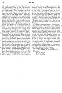
Figure 1 shows a side elevation of a joining plane embodying my invention. Fig. 2 shows an enlarged sectional view on the line 2–2 of Fig. 1, also showing two boards in position to be operated on by the plane, one of said boards formed with a cut such as would be made by the plane. Fig. 3 shows a perspective view of the plane bit detached, and Fig. 4 shows a perspective view of the bolt for clamping the bit to the plane.

Referring to the accompanying drawings, I have used the reference numeral 10 to indicate the body of the plane, provided with a handle 11 at its rear, and a handle 12 at its front. Below the body 11 is a smooth, straight runner 13, cut away at 14 to receive the bit. A groove is formed on the body portion 10 to receive the bit, which groove inclines downwardly and forwardly, terminating in the cut-away portion 14, and it also inclines rearwardly and toward the left of the plane body relative to a transverse line through the plane. This latter inclination may be readily seen in Fig. 2. The plane bit comprises a straight, flat body portion 15 designed to enter the groove in the plane body, and a shank 16 narrower than the part 15, and having its right edge arranged substantially flush with the right edge of the runner so that it will not cut into a board at the right side of the runner. The left edge ofthe shank 16 is arranged with the forward corner 18 thereof projected a slight distance outside of the line of the left side of the runner, and the rear corner lies inside of said line. That is to say, the left side of the bit inclines rearwardly and toward the center of the runner, thus leaving a smoothing edge 18 at the forward corner thereof that projects beyond the runner, and that serves as a smoothing blade for the edge of a board at the left side of the runner against which it is to be moved. The lower end of the bit is sharpened in the ordinary way to cut a shaving from a board over which it is moved. I have used the reference numeral 17 to indicate the right edge of the bit, and 18 the forward corner of the left edge, which is the smoothing center.

I have provided for adjustably securing the bit to the body by means of a bolt 19, having a flattened portion at 20, which bolt is inserted in a suitable opening in the body 10 with its flattened surface engaging the bit body 15, a winged nut 21 being provided on the other end of said bolt. Formed on the right side of the runner 13, in front of the cut-away portion 14 is a vertical groove 22, with a central slot 23 therein. Mounted in said groove is a guide blade 24, and a set screw 25 extends through the blade and through the slot 23, whereby the blade may be set to any position of its adjustment. This guide blade is on the side opposite from the smoothing edge of the bit.

In Fig. 2 of the drawings, I h ave shown the adjacent edge portions of two boards, one of which is to be trimmed down so that it will fit accurately to the other. The board to be trimmed is indicated by the numeral 26. The other board serves as a guide, and is indicated by the numeral 27.

In practical use, I first place the two boards that are to be joined, together on a bench, with the edges that are to be joined adjacent to each other, and as nearly parallel as possible, it being assumed that the boards do not have perfectly straight edges. I then select the board that has the straightest edge and use it as the guide, and proceed to cut away the edge of the other board. I do this by placing the plane in position with the guide blade 24 against the edge of the board that is to be used as a guide while the cutting edge of the bit rests on top of the board that is to be cut away, near its edge. I then cut away one shaving throughout the entire length of the board to be trimmed and obviously the edge of the board that is formed by the cutting away of the first shaving, will be absolutely parallel with the edge of the guide board, I then continue the operation of cutting away one shaving at a time, until the guide blade projects below the board that is used as a guide. When the operation has proceeded. this far, the guide blade is not necessary, as the plane runner will be guided between the edge of the guide board and the edge of the board being cut that was formed by the removal of the shavings thus far made. Then the operator continues the removing of the shavings as before described. It is essential that the edge of the board first being cut be made comparatively smooth by the joining plane, for if it were left rough and uneven, then the edge would have to be smoothed with a smoothing plane, which might result in leaving it out of parallelism with the edge of the guide board, so that it is very essential that a smoothing edge be formed on the left side of the plane bit, which edge projects beyond the runner. It is also important that this smoothing edge be so arranged that it will not cut a shaving from the edge of the board, but it will smooth the edge by removing rough and uneven pieces left thereon by the successive cutting of shavings from said edge portion. Heretofore in dressing down the edge of a board, the plane bit has usually been placed against the edge to be cut. By the use of my improved plane, the bit is placed against the side of the board adjacent to the edge that is being trimmed, and the shavings are cut away successively until the board is entirely cut through from one side to the other. The guide board is firmly fixed in position throughout the entire operation so that when the board is cut through as before described, the resulting edge will be exactly parallel with the edge that was used as a guide, no matter how irregular the edge of the guide board may have been.

Having thus described my invention, what I claim and desire to secure by Letters Patent, is —

A joining plane comprising a straight runner formed with a bit recess, a guide blade adjustably mounted on one side of the runner in front of the bit recess, and abit adjustably mounted, having a sharpened lower edge, the front edge of the bit being inclined from a transverse line through the runner rearwardly, and to the left, the right edge of the bit being contained inside of the line of the right side of the runner, and the left edge of the bit having its forward corner projected outwardly beyond the runner to form a smoothing edge at the forward corner of said left side, and its left side inclined rearwardly and toward the center of the runner, the rear corner thereof being inside of the line of the left side of the runner.

Des Moines, Iowa, Aug. 21, 1907.

WILFRED R. LANSBERRY.

Witnesses:
RALPH ORWIG,
S. F. CHRISTY.

No. 869,016 – Extension-Plane (John V. Petrusich) (1907)

[paiddownloads id=”649″]869016


UNITED STATES PATENT OFFICE.

_________________

JOHN V. PETRUSICH, OF CHICAGO, ILLINOIS.

EXTENSION-PLANE.

_________________

869,016. Specification of Letters Patent. Patented Oct. 22, 1907.
Application filed June 17, 1907. Serial No. 379,311.

_________________

To all whom it may concern:

Be it known that I, JOHN V. PETRUSICH, a citizen of the United States, residing at Chicago, in the county of Cook and State of Illinois, have invented a new and useful Extension-Plane, of which the following is a specification.

This invention relates to improvements in planes.

It is well known that carpenters and others using this class of tool find occasion to use several sizes of the same and the object of this invention is to provide what may be termed an extension plane or a plane in which the several essential sizes of the tool are combined in one.

With this and other objects in view the invention consists in the construction and combination of parts to be hereinafter described, pointed out and claimed in the following specification and illustrated in the accompanying drawings, in which:–

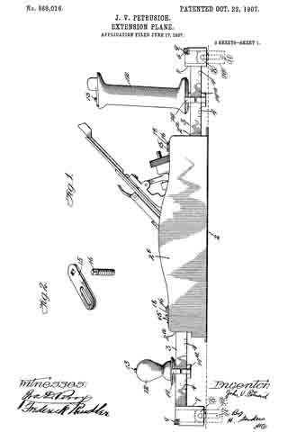
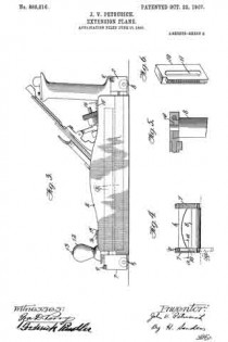
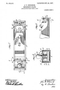
Figure 1 is a side elevation of the device complete. Fig. 2 is a detail of a slotted bar and pin therefor used for locking the extension members. Fig. 3 is a view similar to Fig. 1 showing in dotted lines the position of the extension members when the plane is closed. Fig. 4 is an end of the device partly in section and taken on line d–d Fig. 9. Fig. 5 is a view in section of Fig. 4 taken on line a–a. Fig. 6 is a detail perspective of the rack employed in the extension portion of the device. Fig. 7 is a plan view of the plane closed. Fig. 8 is a front view of Fig. 7, partly in section, and taken on the line b–b. Fig. 9 is a section taken on line c–c of Fig. 7.

Like reference characters indicate corresponding parts throughout the several views.

The reference numeral 2 represents a plane of ordinary or preferred construction having longitudinal sockets 2a opening in either extremity of the side walls 2b of the plane and running horizontally and parallel with each other as shown in Fig. 3.

The numeral 3 represents extension rods adapted to fit slidably into the sockets 2a and having graduations 4 on their lateral surfaces for measuring off the work. Roller-carriers 7 are provided at the external extremities of the extension rods as shown in section in Fig. 4 and as shown complete in Fig. 1, in which are pivoted the rollers 8 for the purpose of carrying the plane smoothly over the work. A brace 6 connects either pair of roller-carriers as shown in Fig. 7 for the purpose of holding the extension rods rigidly parallel.

Either roller-carrier arranged on either left-hand extension rod is recessed on the surface adjacent the roller so that it may carry a rack 10 provided with a slot 11 which engages the pivot of the roller 8. Each left-hand roller-carrier is fiuther provided with a worm 9 which engages the rack 10 for the purpose of raising and lowering the same as shown in detail in Figs. 4 and 5. When the rack 10 is dropped below the lelt-hand edge of the work it serves as a lateral drop guide to keep the plane flush with that edge of the work as shown in Fig. 1.

12 represents a knob of the plane provided with a screw 13 running the entire length of the same and protruding beyond the lower extremity thereof.

14 represents the upper section of a clamp slidably arranged on the extension rods and provided with a threaded aperture to receive the screw 13 protruding from the knob 12 which is seated on said portion of the clamp.

14a is the lower section of the clamp arranged on the extension rods in a manner similar to the upper portion and provided with a threaded aperture to receive the screw 13 that extends through the upper portion of the clamp. By turning the knob 12 to the right the sections of the clamp 14 and 14a are drawn together and are caused to grip the extension rods firmly thus affording rigid handles to the plane.

15–15 represents a pair of slotted bars arranged on the side walls of the plane by means of the screws 16 movable with said bars. The screws 16 extend vertically through the side walls of the plane to the sockets 2a and when the slotted bars are turned at right angles with the side walls of the plane the screws 16 engage the extension rods resting within the said sockets and hold them firmly.

17 represents a horizontal connecting link pivoted at 18 and engaging the slotted bars 15 in the manner shown in Fig. 7. By turning this horizontal link until it lies in a straight angle with the two slotted bars it will cause the screws 16 to engage the extension rods as above described. Thus it will be seen, the extension rods can be partly withdrawn from their sockets and locked in that position.

Either end of the plane is provided with similar extension apparatus and hence a description of that on one end is a description of the apparatus on the other.

Having fully described my invention, what I wish to claim and secure by Letters Patent of the United States is:

1. In a plane, extension means journaled in the side walls thereof, a sliding clamp mounted on said extension means, a knob seated on said sliding clamp and supporting means terminally carried by said extension means substantially as described.

2. In a plane, extension means journaled in the side walls thereof, an extension stop carried on the side walls thereof, a sliding clamp mounted on said extension means, a knob seated on said sliding clamp, roller-carriers terminally arranged on said extension means, a roller pivoted within said roller-carriers and a lateral drop guide carried by said roller-carrier substantially as described.

3. In Combination with a plane having longitudinal sockets in the side walls thereof, sliding extension rods arranged therein, a. sliding screw-actuated clamp arranged on said extension rods, a knob seated on said clamp by which the same may be anchored or released, roller-carriers terminally carried by said extension rods, a roller pivotally carried by said roller carriers, a brace 6 connecting said roller-carriers and a worm and rack carried by said roller-carriers substantially as described.

In testimony that I claim the foregoing as my own, I have hereto affixed my signature in the presence of two witnesses.

JOHN V. PETRUSICH.

Witnesses:
ROSE GREENBERG,
FREDERICK RINDLER.

No. 842,453 – Plane (Edwin W. Foster) (1907)

[paiddownloads id=”639″]842453


UNITED STATES PATENT OFFICE.

_________________

EDWIN W. FOSTER, OF CENTRAL PARK, LONG ISLAND, NEW YORK.

PLANE.

_________________

842,453. Specification of Letters Patent. Patented Jan. 29, 1907.
Application filed August 3, 1906. Serial No. 329,049.

_________________

To all whom it may concern:

Be it known that I, EDWIN W. FOSTER, a citizen of the United States, residing in Central Park, Long Island, in the county of Nassau and State of New York, have invented certain new and useful Improvements in Planes, of which the following is a specification.

This invention relates to planes for wood-working of various types, wherein a frame carries a cutting member known as the “plane-iron” having a cutting edge substantially rectilinear and which projects a short distance through an aperture in the frame member and at an angle thereto.

The object of the invention is to support the cutting member or plane-iron in the frame, whereby it can be secured in different positions, and thereby the cutting edge of the plane-iron can be brought to form different angles with the longitudinal axis of the frame.

Heretofore the cutting edge of the plane-iron has been set at a right angle to the longitudinal axis of the cutting-iron-that is, is perpendicular to the sides of the frame when these sides are parallel surfaces.

In the present invention the plane-iron can be set with its cutting edge making different angles than a right angle with the longitudinal axis and, if desired, can form an angle of forty-five degrees.

A further object of the invention is to provide in such a plane an organization whereby the portion of the base surrounding the opening for the plane-iron is rotatable, yet always maintains its alinement with the bottom of the form, which member carries the plane-iron, and thereby varies the angle of the cutting edge with the longitudinal axis of the plane.

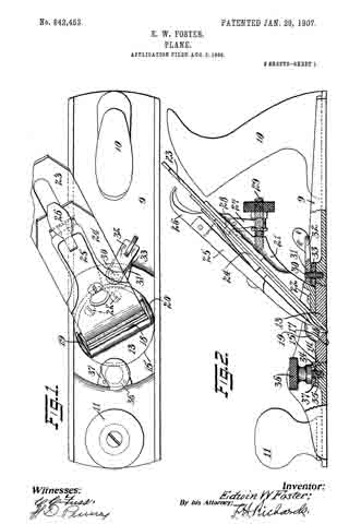
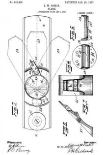
In the accompanying drawings, Figure 1 is a plan view of the device embodying my invention. Fig. 2 is a side elevation, certain parts being shown in vertical section. Fig. 3 is a plan view with the cutting member removed. Fig. 4 is a plan view of the rotary supporting member. Fig. 5 is a section of the latter member, partly shown in elevation. Fig. 6 is a section through the standard for supporting the plane-iron, and Fig. 7 is a front elevation of the latter member.

The frame member 9 is shown as formed of metal and may be provided with the usual handle 10 at the rear and gripping-knob 11 at the front. The frame is provided with an opening in its bottom, and a cutting member is supported in the frame to be adjustably secured with the cutting edge projecting through the opening, whereby the plane-iron can be clamped with its cutting edge extending at different angles with the longitudinal axis of the frame member. This longitudinal axis is denoted by the broken line x x. In Fig. 3 the broken-line positions of the cutting edge indicate some of the adjustable positions in which the cutting member can be clamped. In these positions the cutting edge makes an angle with the line of the path of movement of the edge which is other than a right angle. This will have the effect of making a somewhat spiral shaving and is of great advantage where the grain of the wood does not follow the path of movement of the plane — that is, is not parallel with the longitudinal axis of the plane. By properly adjusting this angle the cutting edge of the plane can be caused to operate substantially perpendicular or at right angles to the oblique grain of the wood.

In the construction illustrated the frame is provided with a circular opening 12 in its bottom, and in this opening a supporting member 13 is rotatable. The wall of the opening 12 is provided with a shoulder portion 14, formed by having its bore enlarged at 15, and the rotary member 13, that is in the nature of a turn-table, has its periphery similarly shaped, providing a shoulder 16, resting on the shoulder 14, thereby preventing downward movement of the rotary member through the opening. In this position the bottom face 17 ofthe rotary member is preferably flush with the bottom of the frame member. The rotary member 13 is provided with a slot 18 for the reception of the plane-iron that extends across within a short distance of the periphery. At each end of the slot 18 the member may be reinforced by means of lugs or raised portions 19 and 20 for strengthening the member at such parts. The edges of the slot 18 is preferably beveled at the upper part for the reception of the plane-iron on one side and to facilitate the escaping of the shaving on the other side.

Any suitable means may be provided for securing a cutting member to the rotary member with its edge projecting through the slot 18. When the cutting member is located and secured to the rotary member, the latter can be oscillated in its bearing in the frame, which will bring the edge of the cutting-iron to form different angles with the longitudinal axis x x of the plane. In all such positions the cutting member will enter the work at exactly the same depth — that is, will have the same adjustment — so that this rotary adjustment or swinging of the cutting-iron will not effect its cut and will not require further adjustment of the cutting member.

In the construction shown the rotary supporting member 13 has a standard or carrier 21 secured thereto in any suitable manner, as by screws 22, and extends upward, being inclined rearwardly at the usual angle formed by the plane-iron. The plane-iron 23 with its cap member 24 and clamp 25 are carried by the supporting member 21 and may be locked thereto in adjustable positions by the clamp-lever 26 in the usual manner. A usual form of screw-and-lever adjustment is shown, in which a lever 27, projecting into the iron at 23, is adjusted by a screw 29, that will vary the depth of out of the plane-iron.

Suitable clamping means are provided whereby the rotary supporting member 13 may be securely held in any position of adjustment. In the construction shown a screw-bolt 30 is carried by the frame member and engaged by a nut member 31, having an arm 32, by which it is swung. A clamping-plate 33 is placed between the screw and the frame and overhangs the edge of the rotary member 13. By turning the nut the latter plate will tightly engage the member 13 and force the shoulder portions of the member and frame together, locking them in adjusted positions.

If desired, another clamping member may be provided at the front portion of the plane comprising a screw 34, tapped into a threaded aperture 35 in the frame, the screw being operated by a mill-head 36. A clamping-plate 37 is engaged by the screw and presses the top of the rotary member 13, clamping the shoulder portions of the rotary member and frame together. When it is desired to vary the angle of the cutting edge, the screw members of the clamps are turned upward, releasing the rotary member 13. This member, with the plane-iron, is then swung to the desired position, either perpendicular to the axis of the plane or at any desired angle therewith. Thereupon the screw members of the clamp are tightened and the plane-iron is securely locked in such adjusted position.

Having thus described my invention, I claim —

1. In a plane, the combination of a frame member having a circular opening in its bottom containing the annular shoulder, a supporting member rotatable in said opening and having an annular shoulder engaging said shoulder whereby the lower face of the member will be substantially flush with the sole of the frame, the supporting member having a slot therein, a plane-iron carried by the supporting member and projecting into said slot, a clamping-plate arranged to engage the top of the frame and the supporting member at the rear of the frame, and a swinging lever on the frame and arranged to press the clamping-plate against the said portions of the frame and support to lock the support in adjusted positions.

2. In a plane, the combination of a frame member having a circular opening in its bottom containing the annular shoulder, a supporting member rotatable in said opening and having an annular shoulder engaging said shoulder whereby the lower face of the member will be substantially flush with the sole of the frame, the supporting member having a slot therein, a plane-iron carried by the supporting member and projecting into said slot, a clamping-plate arranged to engage the top of the frame and the supporting member at the rear of the frame, a swinging lever on the frame and arranged to press the clamping-plate against the said portions of the frame and support to lock the support in adjusted positions, and a clamping member engaging the top of the frame and of the supporting member at the front of the frame.

EDWIN W. FOSTER.

Witnesses:
WILLIAM H. REID,
JOHN O. SEIFERT.

No. 739,014 – Bench-Plane (Clinton E. Lincoln) (1903)

[paiddownloads id=”590″]739014


UNITED STATES PATENT OFFICE.

_________________

CLINTON E. LINCOLN, OF KINSTON, NORTH CAROLINA.

BENCH-PLANE.

_________________

SPECIFICATION forming part of Letters Patent No. 739,014, dated September 15, 1903.
Application filed December 17, 1902. Serial No. 135,538. (No model.)

_________________

To all whom it may concern:

Be it known that I, CLINTON E. LINCOLN, a citizen of the United States of America, residing at Kinston, in the county of Lenoir and State of North Carolina, have invented certain new and useful Improvements in Bench-Planes, of which the following is a specification, reference being had therein to the accompanying drawings.

My invention relates to certain new and useful improvements in bench-planes, and has for its object a plane which upon its return or idle stroke will automatically lift the cutting-blade sufficiently above the under face of the plane so that the cutting-blade will not scrape along the wood being planed, which, as is well known, dulls the edge of the cutting-blade.

A further object of the in vention is the provision of means whereby the cutting-blade and its supporting mediums may be held in raised position for the purpose of fixedly securing the cutting edge of the blade sufficiently above the under face of the plane in order that the latter may be stored away either in a chest or in a tool-cabinet, thereby preventing any damage being done to the cutting edge of the blade should the plane be in contact with any objects.

Briefly described, the invention may be said to broadly consist of a supporting medium for the cutting-blade, which supporting medium at its one end is suitably pivoted to the plane-stock and at its other end supports the cutting-blade, a handle being arranged on the supporting medium and a spring being interposed between the under side of the supporting medium and the plane-bottom, this spring normally retaining the supporting medium in an elevated position, but possessing sufficient resiliency to enable it to be readily depressed, whereby the cutting edge of the blade may be projected sufficiently within the plane-mouth to enable a shaving to be taken off the object planed when sufficient force or pressure is applied to the handle in order to propel the plane during its cutting-stroke.

With the above and other objects in view my invention further consists in the novel details of construction and combination of parts to be described in the following specification and then set forth in the claims.

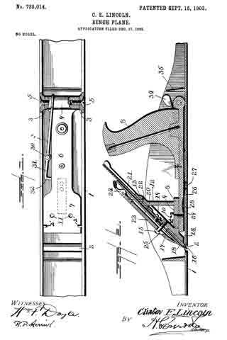
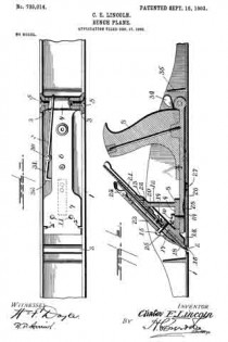
Referring to the accompanying drawings, forming a part of this application, wherein like numerals of reference indicate similar parts throughout the several views, Figure 1 is a top plan view of my improvement, showing the handle removed as well as the intermediate mechanism carrying the cutting-blade; and Fig. 2 is a longitudinal sectional view of the plane embodying my improvements.

The stock of the plane is designated at 1, the bottom of the plane being provided with the usual mouth at 2. At the rear end of the plane and along the sides thereof at opposite points are provided inwardly-extending projections 3, suitably bored and countersunk on their outer sides. Between these projections is received a knuckle 4, which is also suitably bored to register with the bored portions of the projections 3. These registering perforated portions are suitably threaded to receive machine-screws 5, which secure the knuckle with respect to the projections 3 and permit the former to have a free oscillatory movement. This knuckle 4 is the termination of a base-piece 6, which extends transverse to the knuckle and which is materially reduced in width between the knuckle and its forward end 7, the latter being of sufficient width to be readily guided by the sides of the plane-stock. The handle 8 is secured to the rear portion of the base-piece in any approved fashion. This handle and its securing mechanism may be of any of the well-known and common forms in the art.

In order to provide suitable support for the cutting-blade, I secure to the forward end of the base-piece a bracket 8, which consists of a horizontal portion 9, suitably drilled to receive machine-screws 10, which latter pass through drilled and threaded registering portions on the base-piece 6 and which are shown by 11 in Fig. 1. This bracket also embraces a vertical member 12, which at its upper end carries an angularly-disposed integral extension 13 for a purpose shortly to be referred to. The horizontal portion 9 also carries an angular piece 14, whose lower end is adapted to contact with the upper face of the plane-bottom, and thereby limit the downward movement of the base-piece when pressure is applied thereto through the medium of the handle when a forward or cutting stroke of the plane is being carried out. This portion 14 is suitably drilled and threaded and receives in its threaded portion a screw 15, the function of which is well known in the art.

The cutting blade is designated by the numeral 16 and is not of uncommon form, being provided with the usual elongated aperture 17, which is adapted to readily receive the screw 15.

The cap-plate is shown at 18 and is secured to the cutting-blade by means of the screws 19, the cutting-blade having a pivot-point 20, which extends into and is suitably secured to the lever 21, the latter having a screw 22 secured thereto and to the angular extension 13, which permits the lever 21 to rotate about said screw 22 as a point of pivot and through the medium of the pin 20 permits of any necessary lateral adjustment of the cutting-blade.

The clamping-plate is shown at 23 and carries the usual spring-pressed clamping-lever 24, a slot 25 being provided of a slightly elongated nature to readily receive the screw 15.

Under normal conditions, as heretofore stated, the base-piece of the cutting-blade, with its intermediate supporting mechanism, is normally retained in such position as will withhold the edge of the cutting-blade sufficiently above the mouth of the plane for the purpose described, to attain which I provide a flat spring 26, which is suitably secured, as at 27, to the upper side of the plane-bottom and which at its forward end is bowed or arched upwardly, as at 28, and is received within a suitable dug-out portion 29 on the under side of the base-piece 6. This spring is of sufficient strength to readily raise the cutting mechanism from out of the mouth of the plane when pressure is released from the handle.

At the rear end of the plane-body is pivotally mounted, through the medium of a rivet or screw 30, a retaining-lever 31, whose forward end is turned at right angles, as at 32, and is of sufficient thickness to readily enter between the under side of the base-piece and the upper side of the bottom in order that it may thereby support the base-piece and prevent the same from moving in a downward plane should pressure be applied upon the handle or should any object be placed upon the handle or cutting mechanism. This end of the lever will prevent the mechanism from being actuated so as to expose its edge to prevent damage being done to the latter. At its rear end this lever is kicked upwardly, as at 33, and is flattened to provide a thumb-piece 34. A suitable fin 35 is formed integral with the plane-stock and is so positioned as to protect lever 31.

In order to prevent undue upward movement of the cutting-blade and its support, I form integral with the inner sides of the plane-stock lugs 2’, which extend inwardly and are so located as to engage the forward end of the base-piece 6, these lugs being indicated in dotted lines, Fig. 2.

It will be seen that by the use of my improvements during each return or idle stroke of the plane the cutting-bit is automatically raised, so that the latter will not scrape upon the wood or the object being planed, which, as is notoriously old in the art, causes a cutting edge to become rapidly dulled, necessitating frequent whettings, which is obviated entirely by the use of my improvements. Further, I desire to call attention to the fact that by the use of a support for the cutting mechanism of the plane, which upon each stroke of the plane moves in a vertical rotary plane, precludes to a certain extent any clogging of the plane-mouth, which, as is well known, is a frequent occurrence attending the use of any plane, since upon the return or idle stroke of the plane, pressure being released upon the cutting mechanism, the latter will move upwardly and bring the cutting edge out of the mouth of the plane and permit shavings or the like which might have clogged in the mouth of the plane to readily free themselves.

In order to carry into practice the objects of my invention, I have found it necessary to employ certain details of construction which may be readily departed from without affecting the spirit and scope of the invention.

Having thus fully described my invention, what I claim as new, and desire to secure by Letters Patent, is —

1. A plane embodying cutting mechanism and support therefor the said support being pivoted at its one end and carrying the plane-handle, and means interposed between the support and the plane-bottom for holding the support normally elevated.

2. A plane embodying cutting mechanism and support therefor the support carrying the plane-handle at its rear end, and being pivoted at said end, and means adjacent the free end of the support for holding the support normally elevated.

3. A plane embodying a support pivoted at its rear end to the plane-body, and carrying the plane-handle at said end thereof, cutting mechanism on the free end of the support, a means for normally retaining said support in an elevated position, and means pivoted to the plane adapted to engage between the support and plane-bottom for preventing downward movement of the support.

4. A plane embodying cutting mechanism, a support therefor pivoted to the plane, and supporting the cutting mechanism at its forward end, a handle on the rear end of the support, and a spring interposed between the support and the plane-bottom.

5. A plane embodying a base-piece or support, pivoted to the plane and carrying a handle at its rear end, and means for supporting the cutting-blade at its forward end, and means interposed between said base-piece or support and the plane-bottom for normally retaining the base-piece or support in an elevated position.

6. A plane embodying cutting mechanism and a support therefor movable in relation to the plane, and means pivoted to the plane-body adapted to be engaged between the said support and the bottom of the plane to retain the support in an immovable elevated position.

7. A plane embodying cutting mechanism and a support therefor pivoted to the plane, a spring interposed between the said support and the plane-bottom, and a lever pivoted to the plane-body for securing said support against downward movement.

8. A plane embodying a support pivoted at its rear end to the plane-body, and carrying the plane-handle thereon, cutting mechanism on the free end of the support, projections on the plane to engage and limit the upward movement of the support, and means for normally retaining the support in an elevated position.

In testimony whereof I affix my signature in the presence of two witnesses.

CLINTON E. LINCOLN.

Witnesses:
PLATO COLLINS,
INEZ WORTEN.

No. 707,368 – Plane-Iron Cap (Justus A. Traut And Henry S. Walter) (1902)

[paiddownloads id=”571″]707368


UNITED STATES PATENT OFFICE.

_________________

JUSTUS A. TRAUT AND HENRY S. WALTER, OF NEW BRITAIN, CONNECTICUT, ASSIGNORS TO
STANLEY RULE AND LEVEL COMPANY, OF NEW BRITAIN, CONNECTICUT, A CORPORATION OF CONNECTICUT.

PLANE-IRON CAP.

_________________

SPECIFICATION forming part of Letters Patent No. 707,368, dated August 19, 1902.
Application filed April 26, 1902. Serial No. 104,811. (No model.)

_________________

To all whom it may concern:

Be it known that we, JUSTUS A. TRAUT and HENRY S. WALTER, citizens of the United States, residing at New Britain, in the county of Hartford, State of Connecticut, have invented certain new and useful Improvements in Plane-Iron Caps, of which the following is a full, clear, and exact description.

Our invention relates to improvements in planes, and particularly to plane-iron caps.

It consists, mainly, in the improvement of what is termed the “cap-iron” or “cap-piece” in that class of planes in which the plane-iron is clamped to a frog by means of a screw or cam. By this invention we are able to construct a plane-iron cap much cheaper than heretofore and more efficient and durable, as well as more adaptable to the uses to which it may be put.

In the drawings, Figure l is a side elevation of a plane embodying our invention. Fig. 2 is a plan view of that part of the plane to which our invention relates. Fig. 3 is a longitudinal section on the center line of Fig. 2. Fig. 4 is a cross-section on the line X X of Fig. 2 looking in the direction of the arrows.

1 is a plane-stock.

2 is a plane-iron.

3 is a forward handle.

4 is a rear handle.

5 is what is commonly termed a “cap-screw, secured to a frog or support 6 for the plane-iron. The cap-iron 9 is so shaped and constructed as to be engaged at an intermediate point by the head of the screw 5 and at each end to bear upon the plane-iron or a plate, such as commonly associated therewith. In the drawings, Fig. 1, the cap is shown as engaging the forward or lower edge of the plane-iron and engaging the upper portion by means of a cam-pressed spring 7, 8 being the cam employed for clamping the parts. Thus far described the construction and operation of the parts are well known, and hence need not be described in detail.

In practice it is essential that the cap-iron shall be very strong and desirable that it be light in weight, and to that end I construct it, preferably, of wrought or sheet metal. The cap-iron includes a broad blade-like portion 91 and a narrower shank 10. The lower edge of the portion 91 engages with the plane-iron or a part thereof near the cutting edge, while the cam 8 is carried on the shank portion 10. The cap then is subjected to strains in a manner similar to a beam supported at the ends and loaded in the middle. For this reason in order to provide sufficient strength the edges of the shank 10 and a portion of the broader part 9 of the plane-iron are bent down at an angle to provide side bars or flanges 101 integral with the body portion of the plane-iron, and hence contributing to the plane-iron great rigidity and strength. Furthermore, the flanges provide a recess in which to receive the pivot-bearing 81 for the cam 8. In addition to this feature of construction, which contributes substantially to the strength of the cap-iron, we provide a corrugation 11, which preferably commences in the shank portion 10 of the cap-iron and extends downwardly toward the broader portion on opposite lines. In addition to these corrugations shorter corrugations 12 12 may be provided in the broader portion of the cap-iron, contributing vastly to the rigidity and strength of the device, which is preferably curved, as shown best in the side views numbered 1 and 3. The particular construction preserves the curved outline of the cap-iron and permits the employment of comparatively light wrought or sheet metal. The flanges 101 form a pocket in which to receive one end of the spring 7, which is preferably fixedly secured to the cap-iron, as well as a pocket for the bearing end of the cam 8 adjacent to the pivot or pin 81, upon which said cam turns. All of the ribs or corrugations extend generally in a longitudinal direction relatively to the cap-piece, and consequently give greater rigidity to it in a lengthwise direction than transversely.

It is advantageous to have the greater strength extend in longitudinal lines. Should the gage of the metal employed in shaping the cap-piece be so light as to permit any flexibility, it would be in a transverse direction at the lower edge only, and hence advantageous in permitting the lower edge of said cap-piece to yield and bear uniformly against the plane-iron or the plane-iron plate, which is usually employed therewith in planes of the class to which our invention is particularly applicable. In Fig. 4 it will be seen that the ribs are preferably hollowed on the under side, the said view showing the under side of said cap-piece uppermost.

What we claim, and desire to secure by Letters Patent, is —

1. In a plane, a cap-iron having flanges on opposite sides at its upper end, and ribs extending longitudinally of said iron.

2. A plane-iron cap for a plane having corrugations or ribs extending longitudinally thereof, substantially as described.

3. A plane-iron cap for a plane having corrugations or ribs 12 and 12 in the body and extending longitudinally thereof, as described.

4. A plane-iron cap for a plane having corrugations or ribs 11 extending up the shank and 12, 12 in the body extending longitudinally thereof, substantially as described.

Signed at New Britain, Connecticut, this 24th day of April, 1902.

JUSTUS A. TRAUT.
HENRY S. WALTER.

Witnesses:
W. J. WORUM,
EVERETT G. HOFFMAN.

No. 679,424 – Plane (Ludwig Kemline) (1901)

[paiddownloads id=”553″]679424


UNITED STATES PATENT OFFICE.

_________________

LUDWIG KEMLINE, OF PINOLE, CALIFORNIA.

PLANE.

_________________

SPECIFICATION forming part of Letters Patent No. 679,424, dated July 30, 1901.
Application filed October 27, 1900. Serial No. 34,625. (No model.)

_________________

To all whom it may concern:

Be it known that I, LUDWIG KEMLINE, a citizen of the United States, and a resident of Pinole, in the county of Contra Costa and State of California, have invented a new and Improved Plane, of which the following is a full, clear, and exact description.

The purpose of this invention is to provide a plane or other tool with a handle which may be adjusted transversely of the plane, so as to place the hand of the user in any position desired with respect to the transverse extent of the plane. By these means the operator may avoid bruising his hands or otherwise interfering with the work when it is of such character as will make it inconvenient to use the tool with the handle in the middle thereof.

This specification is the disclosure of one form of the invention, while the claims define the actual scope thereof.
Reference is to be had to the accompanying drawings, forming a part of this specification, in which similar characters of reference indicate corresponding parts in both views.

Figure 1 is a side view of the invention with parts in section, and Fig. 2 is a section on the line 2 2 of Fig. 1.

The plane is constructed in the usual manner, except that the body is formed with two transverse grooves a, which open at the upper side of the body and which are undercut, as shown. The cross-sectional form of the grooves a is immaterial so long as the opening at the top of the grooves is of less width than the opening below the top. The purpose of this is to hold in the grooves the blocks b in such a manner as to prevent the blocks from moving upward or transversely out of the grooves. These blocks are freely movable longitudinally of the grooves, however, and the handle c of the plane is attached to the blocks through the medium of a face-plate d and screws e, passing through the base-plate and into the blocks, as best shown in Fig. 2. The base-plate d is provided with transverse ribs d’, which fit in the upper sides of the grooves a, and serve to assist in holding the base-plate in position. The base-plate is preferably of metal and fastened to the handle c by screws or other devices, as shown.

Having thus described my invention, I claim as new and desire to secure by Letters Patent —

1. A plane or analogous tool having an undercut groove in the upper side thereof, said groove extending transversely of the plane, a block adjustably mounted in the groove, a handle, a base-plate on which the handle is mounted, and a fastening device extending between the base-plate and block to bind the block against the walls of the groove and adjustably hold the handle.

2. A plane or analogous tool having two undercut grooves formed in its upper side, said grooves extending transversely of the plane, a block adjustable in each groove, a base-plate extending from one groove to the other and having ribs fitting in the grooves, fastening devices extending between the block and the base-plate, and a handle fastened to the base-plate.

In testimony whereof I have signed my name to this specification in the presence of two subscribing witnesses.

LUDWIG KEMLINE.

Witnesses:
JAMES SILVAS,
A. McCULLOUGH.

No. 659,287 – Bench-Plane (Edward O. Carvin) (1900)

[paiddownloads id=”548″]659287


UNITED STATES PATENT OFFICE.

_________________

EDWARD O. CARVIN, OF VALLEY SPRINGS, CALIFORNIA,
ASSIGNOR OF ONE-HALF TO T. J. FRENCH, OF SAME PLACE.

BENCH-PLANE.

_________________

SPECIFICATION forming part of Letters Patent No. 659,287, dated October 9, 1900.
Application filed June 14, 1900. Serial No. 20,364. (No model.)

_________________

To all whom it may concern:

Be it known that I, EDWARD O. CARVIN, a citizen of the United States, residing at Valley Springs, in the county of Calaveras and State of California, have invented certain new and useful Improvements in Planes; and I do hereby declare the following to be a full, clear, and exact description of the invention, such as will enable others skilled in the art to which it appertains to make and use the same.

This invention relates to carpenters’ planes, and more particularly to the means whereby the handle is susceptible of adjustment to a variety of positions to meet diiferent conditions to facilitate the work and secure ease and comfort to the workman.

The improvement consists of the novel features and the details of construction, which hereinafter will be more fully set forth, and finally pointed out in the appended claims.

In the drawings, Figure 1 is a side elevation of a plane constructed in accordance with and embodying the essential features of the invention. Fig. 2 is a central longitudinal section thereof. Fig. 3 is a top plan view, parts being broken away. Fig. 4 is a detail view showing different mountings for the handle. Fig. 5 is an end view of the construction shown in Fig. 4. Fig. 6 is a detail view showing different means for securing the handle in an adjusted position.

Corresponding and like parts are referred to in the following description and indicated in all the views of the drawings by the same reference characters.

The body 1 of the plane may be of any size and pattern, according to the style of plane, and is provided with a throat 2, adapted to deliver the shavings at one side of the plane, said throat extending transversely of the body and flaring from one side thereof to the other. The rear or heel portion of the body is reduced in depth to enable the handle 3 to be as low down as possible, and the heel portion 4 is reinforced by a horizontal plate 5, secured thereto and provided at its ends with vertical extensions 6 and 7, the latter projecting above and below the plate 5, as shown, the upper extension receiving the rear end of the handle-support 8 and the lower extension overlapping the rear end of the heel portion 4. The parts 5, 6, and 7 are of integral formation and are secured to the parts of the body in any substantial manner. The bit 9 is secured to the lower face of the body 1 in the rear of the throat 2 and is adjustable longitudinally to compensate for wear incident to sharpening. Clamp-screws 10 are let into the body 1 and their heads fit countersunk portions of longitudinal slots 11, formed in the bit, so as not to project beyond the lower face thereof. After the bit has been properly positioned it is secured by tightening the clamp-screws 10, and in order to prevent possible slipping of the bit the latter is formed upon its top side or the face adapted to lie adjacent to the lower side of the body 1 with transverse serrations or Iine teeth 12, which bite into the face of the body and positively hold the bit in the adjusted position after the clamp-screws have been properly tightened. The bit 9 protects the lower face of the body 1 and by being disposed in the manner set forth operates by a more direct cut, whereby knots and timber are adapted to be readily cut across grain.

In order to regulate the depth of out or thickness of shaving, a gage-plate 13 is located in advance of the throat 2 and is vertically adjustable, any suitable means being employed to effect this result, and, as shown, companion set-screws let are threaded into the body of the plane and make swivel connection at their lower ends with bosses provided upon the top side of the gage-plate 13, said set-screws being adapted to be turned by means of thumb-buttons 15 at their upper ends. Jam-nuts 16 are fitted to the set-screws 14 to hold the latter in the required position. By turning the set-screws either to the right or to the left the gage-plate can be lowered or raised, according to the desired thickness of shaving to be cut.

The handle-support 8 is a rod or bar centrally disposed with reference to the body 1 and secured at its ends to the vertical extensions of the plate 5. The handle 3 is adjustable on the support 8, so as to be brought nearer to the cutting edge of the bit or farther away therefrom, according to the nature of the work and the convenience to the user. The handle, in addition to its longitudinal adjustment with reference to the plane, can be turned to any desired angular position either to the rightor to the left, thereby enabling the plane to be used in angles and close quarters, where it would be inconvenient to grasp the handle and manipulate the plane if said handle occupied a vertical position. Any means may be employed for securing the handle in the required position, and, as shown in Figs. 1, 2, and 3, a pair of nuts 17 is mounted upon the rod 3, which latter is screw-threaded throughout its length, the handle 3 being clamped between the nuts of the pair.

In the construction shown in Figs 4 and 5 the rod or bar 8a is formed in a side with a series of openings 18, and the handle 3 is provided with a spring-actuated pin 19 to enter any one of the openings 18 and hold the said handle in an adjusted position, the pin 19 being operated by means of a thumb-latch 20, pivoted to the offset portion of the handle. This support 8a is mounted in the vertical extensions of the plate 5 so as to turn and is provided at its rear end with a spring-arm 21, provided with a stud 22 to enter one of a series of openings 23, formed in the rear face of the vertical extension 7, whereby the handle is positively secured when turned either to the right or to the left from a vertical position. The construction is such as to admit of the body 1 being formed of wood, the plate 13 and the bit 9 forming a metal surface for the lower side thereof to protect it from wear and injury. The depression of the bit enables it to operate by a more direct cut, whereby it will pass more easily through knotty wood and across grain without disturbing the fibrous structure of the material to such an extent as to leave a rough surface commonly experienced when dressing knotty timber by planes of ordinary construction. In the event of the body 1 being of metal or other material the plate 13 and the bit 9 form a facing therefor.

Fig. 6 shows the handle 3 mounted upon a smooth rod 8b and provided with a clamp device consisting of rod 24, having its inner end portion threaded to coact with a nut 25, let into the handle and having its outer end bent, as at 26, to form a grip for turning the rod to release or secure the handle.

Having thus described the invention, what is claimed as new is —

1. In combination with a carpenter’s plane, a handle adjustable lengthwise of the plane and to any angular position, and means for securing the handle in an adjusted position, substantially as set forth.

2. A carpenter’s plane having its rear portion rednced upon its top side for a short distance from its rear end, a support disposed parallel of the plane and located above the heel thereof, and a handle adjustably mounted upon the said support, substantially as specified.

3. In combination with a carpenter’s plane, a support mounted so as to be turned about its axis, means for turning said support and securing it in an adjusted position, and a handle adjustable on the said support, substantially as specified.

In testimony whereof I affix my signature in presence of two witnesses.

EDWARD O. CARVIN. [L. S.]

Witnesses:
JAMES B. LUDDY,
F. J. SOLINSKY.

No. 620,226 – Joiner’s Plane (John M. Cole) (1899)

[paiddownloads id=”539″]620226


UNITED STATES PATENT OFFICE.

_________________

JOHN M. COLE, OF CLEVELAND, OHIO,
ASSIGNOR TO JOHN J. TOWER, OF NEW YORK, N. Y.

JOINER’S PLANE.

_________________

SPECIFICATION forming part of Letters Patent No. 620,226, dated February 28, 1899.
Application filed October 14, 1898. Serial No. 693,563. (No model.)

_________________

To all whom it may concern:

Be it known that I, JOHN M. COLE, a citizen of the United States, residing in the city of Cleveland, county of Cuyahoga, and State of Ohio, have invented certain new and useful Improvements in Joiners’ Planes; and I do hereby declare that the following is a full, clear, and exact description of the same, reference being had to the accompanying drawings, forming part of this specification.

My present invention relates to joiners’ or bench planes and is in the nature of an improvement upon the invention shown in Letters Patent No. 504,562, issued to me September 5, 1893.

The objects of my present invention are to render such planes convertible at will and to adapt them by simple and novel mechanisms for doing a very wide range of different classes of work without necessity of multiplicity or complication of parts, so that they may be of especial convenience and usefulness to journeyman workmen and others.

The leading feature of my present invention is comprised in such a construction and arrangement of the throat and of the bit holding and adjustment mechanisms as will permit ready substitution for the broad full-width bits commonly used in this class of planes of bits for different purposes of varying widths and any required conformation of cutting edge and in providing such mechanisms with a means and construction whereby these bits may by manipulation at the will of the operator without loss of time while at work be instantly and sensitively set farther and farther down just prior to each succeeding forward stroke when planing to plane to any desired depth into the wood below the bottom of the stock without blades, runners, or the usual depth-gages, so that with the use of any attachable and suitably adjustable or adjusted fence and of bits of required conformation joiners’ or bench planes may be instantly converted to do any of many classes of work, such as mitering, miter-grooving and miter-tonguing, tonguing, grooving, beading, center-beading, plowing, inside and outside fillistering or rabbeting, chamfering, slitting, dadoing, diagonal or cross-grain channeling, and edge-molding work of any description.

My invention is further comprised in a novel form of universally-adjustable single-rail fence specially well adapted for use in carrying out these features and in certain other novel forms, devices, functional arrangement, and combination of parts, all of which will hereinafter be fully described and claimed.

In the drawings, Figure 1 is a left-hand side elevation of a plane fully assembled containing all of my above-outlined improvements. Fig. 2 is a longitudinal central vertical sectional view of the same, with rear part of the stock and the handle shown in full and a hand shown in position on said handle, illustrating in part the construction and operation of the leading features of my invention. Fig. 2a is a left-hand side elevation similar to Fig. 1, with parts of the stock and fence broken away, further illustrating the operation of the leading features of my invention. Fig. 3 is a cross-section on dotted line 3 3 of Fig. 2, further illustrating the construction and operation of parts of my invention. Fig. 4 is a cross-section on dotted line 4 4 of Fig. 2, further illustrating the construction of certain parts. Fig. 5 is a top side view of the plane-bit bed. Fig. 6 is a bottom side view of the plane-bit clamp-plate with thumb cramp-screw in place. Fig. 7 is a longitudinal central vertical sectional view, similar to Fig. 2, of my improved plane with the fence removed, which represents the same as it is when used as a joiner’s or bench plane. Fig. 8 illustrates the usual type of broad bit used in Fig. 7. Fig. 9 is a front view of my improved plane adapted to grooving. Fig. 10 is a front view of same, showing its adaptation for mitering and miter-grooving. Fig. 11 is a front view of same, showing its adaptation for inside rabbeting and fillistering. Fig. 12 illustrates a grooving-bit. Fig. 13 is a right-hand side elevation further showing the construction, arrangement, and operation of my improved plane when used as shown in Fig. 11. Fig. 14 illustrates the form of bit that may be used in the work illustrated by Figs. 11 and 13. Fig. 15 is a slitting-bit which my improved plane is adapted to use. Fig. 16 is a plan view of a form of shavings-breaker, shown in Figs. 2 and 2a, which may be employed. Fig. 17 is a front view of my improved plane as adapted for side fillistering or rabbeting. Fig. 18 illustrates one form of bit that may be used as in Fig. 17. Fig. 19 is a front view of my improved plane, illustrating its adaptation for chamfering. Fig. 20 illustrates a form of bit that may be used as in Fig. 19, and Figs. 21 and 22 illustrate a form of bit that may be used in my improved plane for cross-grain channeling.

The several figures will hereinafter be more fully described in detail.

Like letters and numerals indicate corresponding parts throughout the respective figures.

A is the stock of the plane, which is of the usual cast-iron pattern, provided with inwardly-projected inclined lugs a a, to which is rigidly secured a bed B by means of screws b b, and provided also with a handle H, a longitudinally-movable slide or throat piece C, screw-knob D, operatively secured to the boss c of said slide or throat piece by a bolt d, rigidly united to the latter and passing through a slot e in the upper wall of a recess f, said stock being provided also with holes g g g’ g’ laterally through the sides thereof, g g of which are surrounded with strengthening-bosses h h, and g’ g’ preferably passing through the lugs a a. The bed B has ledges i i, which are cut away at j j, and above this point they are united by cross-pieces k l, extending downward, the first of which is hollowed out on its upper side at m. These ledges i i in the upper section of the bed are carried down to form walls n n, upon the external side of one of which I place graduation-marks, as shown at o.

In the downwardly-extending cross-pieces k l is journaled and held against longitudinal play a screw-threaded rod p, provided at its uppermost end with a gnarled or milled head q, located so as to be within easy reach of and to be operated by the thumb and finger of the operator. This rod p is preferably made with a left-hand screw-thread. A traveling nut r, correspondingly threaded and carried integrally on a slide s, engages the threaded rod p, so that the former may be moved by the latter up and down on the upper part of the ledges i i. The journal-holes for the screw-threaded rod p are elongated above and below the latter at t t t t, so that there can be no cramping or binding of the rod in the nut r as it travels along its length.

E is a substantially H-shaped holder provided with a screw-threaded socket and clamp-screw u for clamping the bit F and bit-clamp plate G together and connecting the same to the bed B by means of the lower portion of the ledges i i.

The bit-clamp plate G is provided with a gnarled headed cramp-screw I, which passes through its upper end from the top side, the bearing end of which is reduced, so as to engage any one of the sockets v v’ v” in the slide s. It is also provided with a slot w, longitudinally its center, preferably just wide enough to admit the shank of the clamp-screw u, and also has a rib as on its under side at the transversely-reduced upper portion to strengthen the latter.

16y is a shavings-breaker having a hole a’ for entrance of the clamp-screw u and having its upper end reduced and bent downward to engage the slot w.

J is a fence-rail, preferably made in one integral piece, having a narrow flange b’ along one edge and a diagonal rectangular opening c’ on the flanged edge, around which said flange is carried, and provided with transversely-arranged lugs d’ d’, preferably flush with the opposite unflanged edge, to which is hinged, by means of pivots or screws e’ e’ and the medium of disks f’ f’, having screw-threaded thimbles h’ h’, a pair of J-shaped rods i’ i’, the ends j’ j’ of the shorter straight portions of which are screwed into said thimbles h’ h’ to about the distance seen in Fig.
3, and the longer straight portions, which are parallel to the short portions, being entered in the lateral holes g g g’ g’, constituting parallel pivots, so that the semicircularly-curved portions k’ k’ thereof form parallel swinging arms for vertical adjustment of the fence J.

L is an eccentric through which the rearward J-shaped rod is entered, and l’ is the lever for operating the eccentric, the purpose of which is to secure the rods against rotation and against sliding laterally in the holes g g g’ g’, and thereby hold the fence J in vertical and lateral adjustment. In Figs. 1, 2a, 10, 11, and 17 it will be seen that the fence is adjustable angularly to the bottom of the plane by reason of the pivotal screws e’ e’, by means of which also it may be secured at any desired angle against turning.

A plane embodying my improvements may be converted from the common bench or joiner’s plane (shown in Fig. 7) to a grooving-plane (shown in Figs. 2, 2a, and 9) in the following manner: Loosen the screw-knob D, Fig. 7, and push it forward as far as it will go and retighten again, which carries the slide C forward, elongating the front part of the plane and opening the throat thereof very wide, as shown in both Figs. 1, 2, and 2a. Now loosen the cramp-screw I, the end of which, Fig. 7, it will be observed, is in the lowermost socket v, and pull the bit F the clamp-plate G, and H-shaped piece E upward till the latter comes to the open space or interruptions j j in the ledges i i, when these parts will be disengaged from the bed B; remove the clamp-screw u, take out the broad bit 8, Fig. 8, and substitute the grooving-bit 12, Fig. 12, and, if desired, the shavings-breaker 16y, Fig. 16, may also be included, and the whole again dropped into place on the bed B; but before tightening up the clamp-screw u with the bottom of the plane resting on a level surface the cutting edge of the bit is allowed to slide down into contact with that surface, and then the screw-threaded rod p is turned till the lower edge of the traveling nut is opposite the graduation-mark that indicates the desired depth to which the groove is to be planed, and now the cramp-screw I and clamp-plate G are lifted up till the end of the former drops into the uppermost socket v”, when the clamp-screw it is screwed down tight, and afterward the cramp-screw I is also screwed down with gentle tension. The J-shaped rods of the fence J are now entered in the holes g g g’ g’ and through the eccentric L the desired distance and the fence adjusted vertically to about the position shown in Fig. 9 and now securely clamped by the eccentric L. To convert to a mitering-plane, the fence is adjusted as shown by Fig. 10, and the broad bit 8f, Fig. 8, reinserted. To convert to a miter-grooving plane, take out the broad bit and restore bit 12f, Fig. 12, leaving the fence adjusted as shown in Fig. 10. With a proper bit miter-grooving can also by this last adjustment be done. To convert to an inside-rabbeting plane, an L-shaped bit 14f of the form shown by Fig. 14 is used, and the flanged edge b’ of the fence is turned under the bottom of the plane and adjusted to the position shown by Fig. 11, which brings the narrow portion m’ of the L-shaped bit within the opening c’ of the rail of the fence. To convert to an outside-rabbeting plane, a bit 18f of the form shown in Fig. 18 is substituted and substantially similar adjustment of the fence is maintained as shown by Fig. 17. To convert to a chamfering-plane, the fence is preferably adjusted to the position shown in Fig. 19 and a bit 20f of the shape shown in Fig. 20 is substituted. To do channeling, dadoing, or cross-grain work, bits constructed with cutting-lips n’ n’ at their lateral edges, as shown in Figs. 21 and 22, are employed, and the usual temporary gage is made fast to the board in which the channeling or dadoing is to be done as a guide in place of the fence which is removed. To convert to a slitting-tool, the bit, Fig. 15, would be substituted and the fence adjusted to the required position. These several above-described and any analogous conversions will be more readily understood by bearing in mind that they are attainable in a bench or joiner’s plane only in consequence of the leading feature of my invention — to wit, a construction of parts at the throat and provision in the mechanisms for holding movement and adjustment of the bits, whereby the cutting edge of the plane-bit, together with the shavings-breaker and bit-clamp plate, can be by regular gradations at the will of the operator advanced through the throat farther and farther down into the wood below the level of the bottom of the plane, and whereby (without employment of blades, runners, or gages) at each return stroke by a slight turn of the left-hand screw-threaded rod p with the thumb and finger the operator can cut as thin or as thick shavings as he chooses till the nut i has reached the limit of its movement, which, furthermore, may be adjusted to indicate any desired depth, as shown and described, while in the case of inside and outside rabbeting and fillistering a further element is brought into combination — viz., the opening c’ in the flanged edge of the rail of the fence J. The general utility of the improved construction, application and adaptation of the fence will be readily observed.

Those skilled in the art will fully comprehend that by my invention and with bits of required conformation of cutting edge and sole a very great diversity of work can be done, to accomplish which has heretofore required a number of special and in some cases very complicated and bulky planes.

It will be noted that my improved fence is reversible — i. e., may be applied to the right-hand side of the plane-stock, which is sometimes desirable.

I am aware that planes have been constructed with movable throat-pieces for regulating the “bite” of the bit and that such are, indeed, common; but I am not aware that any have before my present invention been adapted to allow of the passage of the cutting end of the bit, the bit-clamp plate, and shavings-breaker together bodily down through the same in the manner and for the purposes I have shown.

I am also aware that mechanisms for clamping and for very limited longitudinal adjustment of plane-bits have been made; but I am not aware that any have before my present invention been adapted for advancing the cutting edge of the bit by the sensitive will of the operator by any desired successional gradations while planing down through the throat of the plane into the wood any desired depth below the bottom of the plane and without the use of blades, runners, or depth-gages.

I am further aware that fences for planes with parallel pivoted arms have been made, and two-part angularly-adjustable rails for plane-fences have also been made; but I am not aware that before my present invention a one-part angularly-adjustable rail plane-fence provided with swinging parallel arms carrying integral parallel pivots and adapted for vertical and lateral adjustment has ever been used or that the rail in any adjustable fence has ever been constructed with an opening in the flanged edge for the purposes I employ the same.

I do not limit myself to the precise means described for accomplishing the gradual advance of the bit into the wood while using the plane, as manifestly other ways might be employed without departing from the spirit of my invention; but,

Having described my invention, what I do claim as new, and desire to secure by Letters Patent, is —

1. In a convertible joiner’s or bench plane, in combination, a widely open or widely-opening throat-piece, a longitudinally-slidable bit-holding mechanism comprising a clamp-plate and shavings-breaker plate adapted to hold vari-shaped bits and to be adjusted entirely through and beyond the throat, and a mechanical device suitably adapted for gradual, sensitive and rigid advancement of the shavings-breaker, bit-clamp plate and cutting end of such bits entirely through or beyond the throat while the plane is being used and at the will of the operator, substantially as and for the purposes shown and described.

2. In a convertible joiner’s or bench plane, in combination, a widely open throat or widely-opening throat-piece, a longitudinally-slidable bit-holding device comprising a clamp-plate and shavings-breaker plate adapted to hold vari-shaped bits and to be adjusted entirely through and beyond the throat, screw-actuated mechanism for gradual, sensitive and rigid advancement of the shavings-breaker, the bit-clamp plate and the cutting end of such bits entirely through or beyond the throat while the plane is being used and at the will of the operator, a one-rail removable, vertically, laterally and angularly adjustable fence, and mechanical means for rigidly securing said fence and its rail after adjustment, the whole constructed and to operate substantially as and for the purposes shown and described.

3. In combination, a convertible joiner’s or bench plane provided with a widely open throat or widely-opening throat-piece, a longitudinally-slidable bit-holding device comprising a clamp-plate and shavings-breaker plate adapted to hold vari-shaped bits and to be adjusted entirely through and beyond the throat, and a mechanical device suitably adapted for gradual, sensitive and rigid advancement of the shavings-breaker, bit-clamp plate and cutting end of such bits entirely through or beyond the throat while the plane is being used and at the will of the operator, a one-rail removable, vertically, laterally and angularly adjustable fence, and mechanical means for rigidly securing said fence and its rail after adjustment, for the purposes shown and described.

4. In combination with a convertible joiner’s or bench plane provided with a widely open throat or widely-opening throat-piece, and a bit-clamp adapted to hold vari-shaped bits to be adjusted entirely through or beyond the throat, a one-rail removable, laterally and angularly adjustable fence provided with an opening for passage of the bit through the flanged edge of said adjustable rail, substantially as and for the purposes shown and described.

5. In combination with a convertible joiner’s or bench plane constructed and to operate substantially as shown and described, a removable, vertically, laterally and angularly adjustable fence, parallel swinging arms, each having long and short integral pivots, the shorter ones pivotally united to the lugs of the rail of said fence by means of screw-threaded thimbles h’ h’ and right-angularly-arranged disks f’ f’, and mechanical means for rigidly securing said fence after adjustment, substantially as and for the purposes shown and described.

6. In a convertible joiner’s or bench plane, in combination, a vertically and laterally adjustable fence, parallel swinging arms, each having long and short integral pivots, lateral sockets in the plane-stock for the longer parallel pivots of said arms, and an eccentric for engagement of one of said long pivots, substantially as and for the purposes shown and described.

7. A convertible joiner’s or bench plane provided with a longitudinally-slidable bit-holding mechanism comprising a clamp-plate, and a shavings-breaker plate, and with mechanical means for gradual and rigid advancement of said shavings-breaker and bit-clamp plates and the cutting end of bits entirely through or beyond the throat while the plane is being used and at the will of the operator, in combination with graduation-marks adjacent to or upon said longitudinally-slidable bit-holding parts, substantially as and for the purposes shown and described.

8. In convertible joiners’ or bench planes, a screw-actuated mechanism adapted for gradual rigid advancement of the bit longitudinally, comprised of a clamp for holding the bit, a holder for connecting the same with the ledges of the bed, a slide provided with two or more sockets v v’ v”, a cramp-screw in the outer end of the clamp-plate to engage said sockets, a traveling nut, a longitudinally-immovable screw-threaded rod engaging said nut, provided with a gnarled head, in combination with a widely open throat or widely-opening throat-piece, constructed, arranged and adapted to be operated substantially as and for the purposes shown and described.

In testimony whereof I have hereunto set my hand, this 2d day of September, 1898, in the presence of two subscribing witnesses.

JOHN M. COLE.

Witnesses:
WARREN M. TOWER,
VINCENT ROSEMON.

No. 597,622 – Plane (John N. Schneider) (1898)

[paiddownloads id=”534″]597622


UNITED STATES PATENT OFFICE.

_________________

JOHN N. SCHNEIDER, OF MENDOTA, ILLINOIS.

PLANE.

_________________

SPECIFICATION forming part of Letters Patent No. 597,622, dated January 18, 1898.
Application filed January 14, 1897. Serial No. 619,148. (No model.)

_________________

To all whom it may concern:

Be it known that I, JOHN N. SCHNEIDER, a citizen of the United States, residing at Mendota, in the county of La Salle and State of Illinois, have invented certain new and useful Improvements in Planes; and I do hereby declare the following to be a full, clear, and exact description of the invention, such as will enable others skilled in the art to which it appertains to make and use the same.

My invention relates to improvements in hand-planes, and has for its object the production of an improved plane the bit of which will be autornatically retired from its operative position during the back stroke of the plane.

A further object is the production of novel mechanism for the adjustment of the bit which may be regulated while the plane is being moved over the surface to be planed and without removing the hand from the handle.

Subordinate to these general objects a still further object of my invention is to provide certain novel and efficient mechanism for accomplishing the various attachments of the several parts of the device, as will hereinafter be made apparent.

To the accomplishment of the objects stated my invention consists in providing a plane-stock with a pivoted bit-stock and with a handle designed by its rotation to regulate the adjustment of the bit-stock and to automatically throw the bit into its operative or inoperative positions as the pressure exerted upon the handle is directed to propel or retract the plane.

In order that the utility of the invention may be readily understood, it may be remarked that in the usual manipulation of devices of this general character the backward movement or stroke of the plane is accompanied by the abrasion of the bit, which gradually turns the cutting edge and necessitates an additional pressure upon the plane in order to secure a proper bite upon the material to be planed. It is necessary in order to avoid this abrasion and the consequent wear and distortion of the cutting instrument to raise the plane entirely from the surface of the material during its back stroke, which is not only inconvenient, but where a large plane — as, for instance, a jack-plane — is employed it is absolutely impossible, and the consequence is that the plane is dragged back, the grit upon the material serving to grind the rear face of the cutting edge and finally forrning a shoulder thereon, which must be actually forced into the surface of the wood in order to secure a bite sufficient to remove a shaving. It has also been necessary heretofore to discontinue the operation of planing when it has been desired to adjust the bite of the cutting-bit, and, as I have stated, the object of the present invention is to overcome the wear upon the cutting edge and the necessity for discontinuing the rnanipulation of the plane when it is desired to accomplish the adjustment of the bit.

In the accompanying drawings, forming a part of this specification, Figure 1 is a central vertical section through my device, showing the bit in an operative position. Fig. 2 is a side elevation, partly in section, of a portion of a plane, showing the bit retired or in inoperative position. Fig. 3 is a top plan view with certain of the parts broken away. Fig.
4 is a top plan view of a portion of the bit-stock and the mechanism supported thereby. Fig. 5 is a bottom plan view of the subject matter of Fig. 4, showing the lateral adjustment of the bit in dotted lines and illustrating a modified form of the fulcrum-pin. Fig. 6 is a detail view of a portion of the adjustment-sleeve index and locking-plate and the upper section of a bit-stock-adjusting bolt. Fig. 7 is a plan view of my indicator and locking-plate. Figs. 8 and 9 are detail views of the upper extremity of the bit-adjusting bolt. Fig. 10 is a view of a modified form of the mechanism comprehended by the parts 40 and 42. Fig. 11 is a diagrammatic view illustrative of the edect of the ordinary manipulation of the plane upon the cutting edge of its bit.

Referring to the numerals on the drawings, 1 indicates a plane-stock consisting, as usual, of a sole-plate 2, provided with a transverse bit-aperture 3 and with frame or side pieces 4, preferably of the configuration illustrated.

5 indicates the front guiding knob or handle, secured upon the sole-plate in the usual manner, and 6 indicates a bit-stock consisting of a bed-plate 7, provided with a bit-iron and its retaining and lateral adjusting mechanism and fulcrumed between the side pieces 4 by a fulcrum-pin 3, secured at its opposite ends to the side pieces 4 and located a suitable distance to the rear of the bit-aperture 3 and preferably near the lower extremity of the bed-plate.

9 indicates the handle of my device, consisting, preferably, of the handle-casing 10, having an internal adjustment-sleeve 11. secured thereto, as by a screw 12, and internally screw-threaded in opposite directions adjacent to its opposite extremities for the reception of the separated and oppositely screw-threaded upper and lower sections 13 and 14; of the adjustment-bolt 15, the lower extremity 16 of which is pivoted upon the handle-pintle or fulcrum-pin 17, carried by a pair of upwardly-extending lugs 13, carried by the sole-plate. The lower end of the handle-casing is preferably recessed, as at 19, for the reception of the lugs 13, in order to accommodate longitudinal adjustment of the former. The rear extremity of the bit-stock is preferably bifurcated, and the bifurcated extremities are provided with slots 22, arranged tangentially with respect to an are described by the upper extremity of the adjustment-bolt 15 when the latter is swung upon the fulcrum-pin 17. The upper extremity of said adjustment-bolt is provided with a bearing-thimble 23, disposed at right angles to the bolt and provided with a bore 24: and with a transverse slot 25, designed for the reception of the locking-lever 26, carried by a pin 27, passed through the bore 24 in the thimble 23 and designed to be engaged by the slots 22 in the bifurcated extremities 20 and 21 of the bit-stock bed-plate.

29 indicates what I will term a “locking and indicating plate” secured upon or made integral with the upper extremity of the adjustment-sleeve 11 and provided with a series of radial notches 30, designed to receive the locking end 31 of the locking-lever 26, which latter is spring-actuated, as by a bent spring 32, passing through a spring-aperture 33 in the adjustment-bolt, and bearing at one extremity against the handle 34 of the locking-lever.

It will now be observed that the bit-iron 35, carried by the bit-stock, will be projected through the bit-aperture 3 in the sole-plate or will be retracted to a position above the lower surface of the sole-plate by the oscillation of the bit-stock upon the fulcrum-pin 3, and it is for the purpose of accomplishing this movement of the bit for the purpose of throwing it into the operative position or of retiring it to the inoperative position as the plane is moved forward or rearward that I have employed a pivoted or oscillating handle having loose connection with the upper extremity of the bit-stock.

When the plane is propelled, as in use, pressure is exerted upon the handle 9 in the direction of the movement of the plane, causing the extremities of the pin 27, carried at the end of the adjustment-bolt 15, to move to the bottom of the slots 22, swinging the bit-stock upon its pivot and throwing the cutting edge of the bit 35 into its operative position below the sole-plate 2. The shaving is now removed from the surface of material to be planed and extends through the aperture 3 in the usual manner. The end of the stroke having been reached, pressure is now exerted by the operator upon the handle 9 in the opposite direction, causing it to be oscillated rearwardly or in the direction of the retraction of the plane, and the pin 27 will seek the opposite ends of the slots 22, which by reason of the relation of said slots and the direction of movement of the pin will cause the bit-stock to be again oscillated upon its fulcrum-pin 8, raising the cutting edge of the bit 35 to the inoperative position, as indicated in Fig. 2 of the drawings. The shaving which would otherwise accumulate in the aperture 3 is by this operation ejected from immediate proximity to the aperture by the movement of the bit.

Supposing now it is desired to adjust the bite of the plane iron or bit, by which I mean the distance it will project below the sole-plate in the operative position, the thumb of the operator is placed upon the handle 34: of the locking-lever, depressing it and causing the locking end 31 of the lever to be disengaged from the locking-plate 29. The handle 9 is now rotated in one direction or the other, as it is desired, to lengthen or contract the adjusting-bolt 15, it being observed that by reason of the oppositely screw-threaded connections of the sections of the adjustment-bolt and adjustment-sleeve the bolt-sections will be drawn together or separated by the rotation of the handle and thus caused to adjust the angle of inclination of the bit-stock, which, as will be apparent, will regulate the bite of the plane-bit. As soon as the desired adjustment has been accomplished the handle 34 of the locking-lever is released and the spring 32 will elevate the handle and will bring the locking end of the lever into engagement with the adjacent notch in the locking-plate 29. By this means the adjustment of the bit-stock and its iron is fixed.

It is obvious that the adjustment just described can be effected without interrupting the operation of planing and without in any manner affecting the operation of the device for the purpose of throwing the bit into or out of its operative position. For the purpose of determining the extent of the adjustment I prefer to number the notches upon the looking and indicator plate 29, as indicated in Fig. 7 of the drawings, it being apparent that the degree of rotation of the handle, as indicated by the progression of the notches, will determine the extent of the adjustment effected through the mechanism described, and which I will term “bit-adjusting” mechanism. When it is desired to throw the locking-lever out of operation — as, for instance, when nicety of adjustment is not required — the spring 32 may be passed through the aperture 33 to the position indicated in dotted lines of Fig. 1 of the drawings, in which position it will hold the locking end of the locking-lever out of operation, and the handle may then be turned in either direction at will.

Having now described the bit-actuating mechanism and the bit-adjusting mechanism, I shall now proceed to a description of the novel mechanism by means of which the bit or iron is adjustably secured upon the bed-plate of the bit-stock.

36 indicates a bit-supporting plate pivotally secured to the face of a depressed portion of the bit-stock by means of a bit fulcrum-bolt 37, screwed into the bed-plate 7 at a point adjacent to the fulcrum-pin 8 and provided with a conoidal portion 38, designed to be received by a correlatively-shaped aperture 39 in a bit-supporting plate 36.

40 indicates the bit-adjustment bolt, secured at one extremity to the plate 36 near its end and projecting through a curved aperture 41, designed to accommodate its movement in the bed-plate 7, incurred in a degree corresponding to the arc of movement of the adjustment-bolt.

42 indicates a thumb-nut screwed upon the extremity of the bolt 40 and designed by its abutment against the lower surface of the bed-plate to secure the bolt in its adjusted positions in the manner hereinafter made apparent. The iron or bit 35 is now placed upon the surface of the stock and the plate 36 and is secured to the superimposed cap-iron 43 by the screw-bolt 44, the head of which its closely within an aperture in the plate 36 to prevent lateral movement of the bit and cap iron upon said plate, an elongated recess being provided in the surface of the stock to permit the movement of the head ot the bolt 44, when the plate 36 is swung upon the pivot for the purpose of alining the cutting edge of the bit with the surface of the sole-plate 2. The bit-iron is provided with an elongated slot 45, designed to accommodate the bolt 37 when the bit is moved longitudinally, and the cap-iron 43 is provided with an aperture 46, through which said bolt is passed, as illustrated.

47 indicates a compression-lever provided with a pointed extremity 49, designed to bear against the spring end 50 of the cap-iron, which bears against the bit adjacent to its cutting edge. The compression-lever is preferably provided with an aperture 51, correlative in size and shape with the hexagonal head of the bolt 37 and designed to permit the same to be passed therethrough, and with a preferably small recess 52, extending from the aperture 51, into which recess the bolt proper is slipped, as indicated in Figs. 1 and 4 of the drawings.

53 indicates a compression-bolt screwed to the rear end of the compression-lever and designed to abut against the cap-iron. It will thus be seen that the bit is clamped firmly against a suitable bit-supporting plate 36 and may be swung upon the bolt 37, as indicated in dotted lines in Fig. 5, for the purpose of alining the cutting edge of the bit with the surface of the sole-plate 2.

Summarizing briefly, I have by the construction and arrangement described and illustrated produced a plane provided with means for the lateral and longitudinal adjustment of the bit upon the bit-stock, mechanism for adjusting the bit-stock through the movement of the handle, and mechanism for actuating the bit-stock to throw the bit into or out of operative position automatically as the plane is propelled or retracted, as in use.

I do not desire to limit myself to the details of construction herein shown and described, but reserve to myself the right to change, modify, or vary such details within the scope of my invention.

Having thus described my invention, what I claim as new, and desire to secure by Letters Patent, is —

1. The combination with a plane-stock, bit and oscillatory bit-stock, of a rotary and oscillatory handle operatively connected with the bit-stock, means whereby its oscillation will actuate the bit-stock, and whereby its rotation will adjust its connection therewith, substantially as specified.

2. The combination with a plane-stock, bit and oscillatory bit-stock, of a rotatable plane-handle operatively connected with the bit-stock and means for causing its rotation to adjust its connection with said bit-stock, substantially as specified.

3. The combination with a plane-stock, bit and oscillatory bit-stock, of an oscillatory handle and a slot-and-pin connection between the upper extremity of the handle and bit-stock, substantially as specified.

4. The combination with a plane-stock, bit and oscillatory bit-stock, of an oscillatory handle, bit-adjusting mechanism actuated by the movement of the handle and means carried by the handle for locking said bit-adjusting mechanism, substantially as specified.

5. The combination with a plane, a bit and oscillatory bit-stock, of a rotary handle operatively connected with the bit-stock and designed by its rotation to adjust the same, of an index and locking plate operatively connected with the handle, and a locking-lever operatively connected with said plate, substantially as specified.

6. The combination with a plane-stock, of an oscillatory bit-stock, an oscillatory handle, bit-stock-adjusting mechanism intermediate the handle and bit-stock, a bit adjustable upon the bit-stock, and locking mechanism intermediate of the handle and bit-stock, substantially as specified.

7. The combination with a plane-stock, bit and oscillatory bit-stock, of an oscillatory handle and a sectional adjustment-bolt operatively connected with the handle and with the bit-stock, substantially as specified.

8. The combination with a plane-stock, bit and oscillatory bit-stock, of a sectional adjustment-bolt pivoted upon the plane-stock and operatively connected with the bit-stock, a handle operatively connected with the adjustment-bolt and cooperating locking mechanism carried by the bolt and handle, substantially as specified.

9. The combination with a plane-stock, bit and oscillatory bit-stock, of a sectional oscillatory adjustment-bolt connected with the bit-stock by a slot-and-pin connection, a handle operatively connected with a sectional adjustment-bolt, an indicator and locking-plate carried by the handle and a locking-lever carried by the bolt, substantially as specified.

10. The combination with a plane-stock, bit and oscillatory bit-stock, of a sectional adjustment-bolt operatively connected with the bit-stock, a handle operatively connected with the bolt, a notched indicator and locking-plate carried by the handle, a locking-lever carried by the bolt and a spring designed to be adjusted for the purpose of causing it to actuate the locking-lever or to prevent such actuation, substantially as specified.

In testimony whereof I have signed this specification in the presence of two subscribing witnesses.

JOHN N. SCHNEIDER.

Witnesses:
JOHN W. KNAUER,
EMIL J. HESS.

No. 556,835 – Carpenter’s Plane (George S. Smith) (1896)

[paiddownloads id=”527″]556835


UNITED STATES PATENT OFFICE.

_________________

GEORGE S. SMITH, OF GRAND RAPIDS, MICHIGAN.

CARPENTER’S PLANE.

_________________

SPECIFICATION forming part of Letters Patent No. 556,835, dated March 24, 1896.
Application filed April 20, 1894. Serial No. 508,365. (No model.)

_________________

To all whom it may concern:

Be it known that I, GEORGE S. SMITH, a citizen of the United States, residing at Grand Rapids, in the county of Kent and State of Michigan, have invented certain new and useful Improvements in Carpenters’ Planes; and I do hereby declare the following to be a full, clear, and exact description of the invention, such as will enable others skilled in the art to which it appertains to make and use the same.

My invention relates to an improved carpenter’s plane; and its object is to provide the same with certain new and useful features hereinafter more fully described and particularly pointed out in the claims, reference being had to the accompanying drawings, in which —

Figure 1 is a longitudinal vertical section, on the line 1 1 of Fig. 2, of a device embodying my invention 5 Fig. 2, a plan view of the same with the blade and wedge removed; Fig. 3, a vertical section on the line 3 3 of Fig. 1; Fig. 4, an inclined transverse section on the line 4 4 of Fig. 1, and Fig. 5 details showing openings to receive the adjusting-screw H.
Like letters refer to like parts in all of the figures.

A is the main frame of the plane, B the blade-supporting block, C the blade, D the wedge, E the adjusting-lever, and F the adjusting-screw, all being ot the usual construction.

In a suitable opening near the upper end of the blade-block B and laterally movable therein is a bar G, having a widened outer end, which is formed with lugs G’ to engage the sides of the blade and shift it laterally to square the edge of the same with the under surface of the plane. Said bar G is provided at its lower side with a screw-threaded concave surface engaging the side of a screw H. Said screw is provided with a milled head I and journaled in openings J’ J” in lugs J on the back of the block B. Said openings are elongated in the direction of the bar G, and one of the bearings of the screw H is reduced, and the corresponding opening J” is reduced at the lower end to engage this reduced bearing, whereby the screw is prevented from moving longitudinally.

The bar G is held in place in the block B by a screw K, the head of which screw overlaps said bar at one side for this purpose. By removing this screw K and bar G the screw H may be moved into the upper ends of the openings J’ J” and thence removed longitudinally, and when in place said screw is held by the engaging screw-threaded side of the bar G.

Within a suitable recess in the bottom of the plane and with its rear angle close to the cutting-edge of the blade C is a throat-slide L, having upwardly-projecting bosses L’, extending through elongated openings R. Screws P are inserted in said lugs, whereby the slide L is held in the recess and permitted to move longitudinally therein. A spring N is attached to a suitable yoke-frame M at its upper end and engages the slide L at its lower end to press said slide toward the blade C. A screw O engages said spring and a transverse rib Q, and serves to adjust the spring to determine the approach of the slide L to the blade C and thus adjust the opening or throat in front of said blade. Said block L, being movable and pressed toward the blade C by the spring, will yield to the shaving as it passes through the throat. It can therefore be adjusted very close to the blade and thus cause the tool to do very smooth work.

I am aware that a throat-block of somewhat similar construction to mine and capable of being adjusted to and from the blade has heretofore been patented, but said throat-block was not provided with a spring and was incapable of automatically yielding to the shavings, for which reason it did not prevent clogging of the throat.

I am also aware that an adjustable spring has been proposed to take the place of the sliding throat-block, which spring will of course yield to the shaving passing up through the month of the plane, but it will yield for a time only during the operation of the plane, as the space between its forward surface and the forward wall of the throat soon receives a sufficient quantity of shavings to force and hold the spring into contact with the cutter, thus not only preventing the spring from yielding, but entirely closing the exit for the shavings. By combining the sliding throat-block with a spring, which causes it automatically to yield to the quantity of shavings passing upward into the throat of the plane, said throat will not become choked and an open exit for the shavings is kept at all times, as will be readily seen.

What I claim is —

1. In a plane, the combination with the blade and its supporting-block, said block having elongated openings one of which has a reduced lower end, of a bar, laterally movable in said block, and engaged with said blade, an adjusting-screw for the bar and blade, said screw being seated in said openings in the block and having a reduced end corresponding with the reduction in the end of one of said openings, and a screw in said block, having its head overlapping one side of said bar and securing the same in place.

2. In a plane, the combination with the blade and its supporting-block, said block having an opening near its upper end and also having lugs formed with elongated openings, one of which latter has a reduced lower end, of a bar laterally movable in said block, said bar having a widened end formed with lugs engaging the sides of the blade, an adjusting-screw for the bar and blade, said screw being seated in the openings in the lugs of the block and having a reduced end corresponding with the reduction in the end of one of said openings, and a screw in said block having its head overlapping one side of said bar and securing the same in place.

3. In a plane, the body, having a recess in its under side adjacent to its throat, and also having an elongated opening, an upwardly-projecting rib and a yoke-frame, in combination with a movable throat-block in said recess, having an end extending upward into the throat of the plane and a boss extending through said elongated opening, a screw engaging said boss, a spring secured at its upper end to said yoke-frame and having its lower end engaged with the upturned end of said throat-block, and an adjusting-screw engaging said rib and spring, substantially as described.

4. In a plane, the body having a recess in its under side adjacent to its throat, in combination with a sliding throat-block within said recess, said block having an upturned part, and a spring engaging said upturned part of the throat-block and causing the latter automatically to adjust itself to the quantity of the shavings passing upward into the throat of the plane, substantially as described.

In testimony whereof I affiix my signature in presence of two witnesses.

GEORGE S. SMITH.

Witnesses:
LUTHER V. MOULTON,
LOIS MOULTON.

No. 548,582 – Shavings-Guide For Carpenters’ Planes (Lewis B. McDonald) (1895)

[paiddownloads id=”520″]548582


UNITED STATES PATENT OFFICE.

_________________

LEWIS B. McDONALD, OF LITTLE ROCK, ARKANSAS.

SHAVINGS-GUIDE FOR CARPENTERS’ PLANES.

_________________

SPECIFICATION forming part of Letters Patent No. 548,582, dated October 22, 1895.
Application filed March 31, 1894. Renewed March 28, 1895. Serial No. 543,596. (No model.)

_________________

To all whom it may concern:

Be it known that I, LEWIS B. McDONALD, a citizen of the United States, and a resident of Little Rock, in the county of Pulaski and State of Arkansas, have invented certain new and useful Improvements in Shavings-Guides for Carpenters’ Planes; and I do declare the following to be a full, clear, and exact description of the invention, such as will enable others skilled in the art to which it appertains to make and use the same, reference being had to the accompanying drawings, and to the letters of reference marked thereon, which forin a part of this specification.

Figure 1 of the drawings is a representation of a perspective view of the guide applied. Fig. 2 is a plan view of same, and Fig. 3 is a front end view of same.

This invention has relation to certain new and useful improvements in shavings-guides for carpenters’ planes; and it consists in the novel construction and combination of parts, all as hereinafter described, and pointed out in the appended claims.

The object of the invention is to provide a carpenter’s plane with a simple and effective device of improved character for throwing the shavings from the plane off the bench.

Referring to the accompanying drawings, the letter A designates the stock, B the bit or iron, and C the wedge.

D is the guide, which constitutes the present invention in its combination with the stock in the manner presently described.

This guide consists of a piece of metal bent or arched upwardly over the opening D’ in the stock forward of the wedge, the transverse rear edge a of the metal resting against or in close proximity to the wedge and inclosing with the wedge said opening on three sides. The open side is at the longitudinal front face of the plane, and the guide is inclined downwardly from this side to the opposite side, which causes the chamber formed thereby to gradually increase in height from the back to the front longitudinal edge of the plane. By this arrangement the shavings forced up through the stock into this chamber readily clear themselves and are forced out of the open side of the guide and off the bench.

In some cases, in planes with metal stocks, I may prefer to cast the guide integral with the stock, or it may be a separate piece and be secured thereto by screws or othersuitable means. In the latter case a flange b is formed at the forward edge of the guide to receive the securing-screws, the rear longitudinal edge having, also, a flange c, which is secured to the rear longitudinal face of the stock.

When made separate, the guides will be in different sizes and may be readily applied to any of the ordinary styles of planes having either wooden or metal stocks.

Having thus described my invention, what I claim as new, and desire to secure by Letters Patent, is —

1. The combination with a plane stock and the wedge, of a shavings guide therefor, said guide comprising a plate portion attached to the stock and arched or bent over the opening therethrough and inclosing said opening, with the aid of the wedge, upon three sides, substantially as specified.

2. As a new article of manufacture, a shavings guide for carpenters’ planes, said guide comprising a plate portion arched or bent to adapt it to fit over and around the opening in a plane, and against the wedge thereof, and with said wedge inclose it upon three sides, and having danges for its attachment to a plane stock, substantially as specified.

In testimony whereof I anis my signature in presence of two witnesses.

LEWIS B. MCDONALD.

Witnesses:
JULIUS BRUNDT,
HENRY GRAMLING.

No. 514,226 – Carpenter’s Plane (Charles S. Hinnershotz) (1894)

[paiddownloads id=”501″]514226


UNITED STATES PATENT OFFICE.

_________________

CHARLES S. HINNERSHOTZ, OF READING, PENNSYLVANIA.

CARPENTER’S PLANE.

_________________

SPECIFICATION forming part of Letters Patent No. 514,226, dated February 6, 1894.
Application filed February 4, 1893. Serial No. 460,977. (No model.)

_________________

To all whom it may concern:

Be it known that I, CHARLES S. HINNERSHOTZ, a citizen of the United States, residing at Reading, in the county of Berks, State of Pennsylvania, have invented certain Improvements in Carpenters’ Planes, of which the following is a specification.

My invention relates more particularly to bench planes adapted to be constructed wholly or largely of metal.

The main objects of the invention are, first, to simplify the construction, and the setting and fastening of the bit, and second to make the operation more satisfactory.

The novel features of the invention are fully described in connection with the accompanying drawings and are specifically pointed out in the subjoined claims.

Figure 1 is a longitudinal section of a plane embodying my improvements. Fig. 2 is a plan view of the stock or bed. Figs. 3 and 4 are separate views of the bit-iron and of the adjustable spring plate which forms a portion of the sole.

The stock or bed A as shown is a casting, of which the main part of the base plate a3 forms the rear portion of the sole while the part of said plate forward of the mouth c’ is raised to a higher plane and has secured to its under side by means of a screw bolt b at its forward end a spring plate A’, the rear free end of which extends to the mouth c’ and is capable of being pressed downward from its normal position by means of an adjusting screw b’. This adjustable plate thus forms the forward portion of the sole.

The bit iron C is a plain plate of steel ground to a cutting edge c and slightly curved. This is placed upon the upper face of the base plate a3 of the stock with which it may lie substantially parallel as shown, the curve however being sufficient to permit the cutting edge c to be projected through the mouth c’. It is clamped to the stock by means of a fastener D. This is provided with a clamping screw E as usual, which in pressing downward the rear end of the bit-iron upon the transverse rib a2 on the stock turns the fastener upon its fulcrum trunnions d3 which engage grooves a’ in the side walls a of the stock and causes the forward end d2 of the fastener to firmly clamp the forward end of the bit iron to the stock. This fastener is provided with a handle d and with a break-iron d’ which is carried upward in front of the handle and serves to effectually turn the shavings to one side.

By my improved construction I provide an exceedingly simple plane, very economical in manufacture yet more satisfactory in operation than any plane of its class with which I am acquainted.

Having thus fully described my invention I do not limit myself to the exact construction shown, but —

What I claim is —

The herein-described carpenter’s plane, consisting of the stock or bed, having the portion of the sole atthe rear of its mouth integral with it and the forward portion formed by a separate plate and adjustable to regulate the depth of the cut, said rear portion of the stock having a rib extending upward from its upper side; the curved bit-iron, extending through the mouth of the plane and engaging near its forward end the wall of said mouth and near its rear end the rib of stock; a combined handle and holder for the bit-iron, engaging the bit-iron at its forward end and fulcrumed to the stock near its said forward end; and an adjusting screw, engaging directly the handle at one end and the bit-iron at the other end, said screw serving to press downward and hold the rear end of the bit-iron against said rib and simultaneously to force and hold the forward end of the handle downward to clamp the forward end of the bit-iron against the stock, substantially as described.

In testimony whereof I affix my signature in presence of two witnesses.

CHARLES S. HINNERSHOTZ.

Witnesses:
ED. A. KELLY,
DAVID LEVAN.

No. 510,096 – Bench-Plane (Jacob Siegley) (1893)

[paiddownloads id=”497″]510096


UNITED STATES PATENT OFFICE.

_________________

JACOB SIEGLEY, OF WILKES-BARRÉ, PENNSYLVANIA.

BENCH-PLANE.

_________________

SPECIFICATION forming part of Letters Patent No. 510,096, dated December 5, 1893.
Application filed May 21, 1892. Serial No. 433,924. (No model.)

_________________

To all whom it may concern:

Be it known that I, JACOB SIEGLEY, a citizen of the United States, and a resident of Wilkes-Barré, in the county of Luzerne and State of Pennsylvania, have invented certain new and useful Improvements in Bench-Planes, of which the following is a specification.

This invention relates to certain improvements in bench-planes, and the same consists of a cast-iron bottom and steel side-plates riveted to lugs of said bottom, and of a cap that is provided with a shoulder having set-screws, said shoulder resting on a transverse rod extending between the sides of the supporting frame and screws in said shoulder permitting the adjustment of the cap into higher or lower position, all of which will be fully described hereinafter and finally pointed out in the claims.

In the accompanying drawings, Figure 1 represents a side elevation of my improved bench-plane. Fig. 2 is a vertical longitudinal section of the same. Fig. 3 is a detail vertical transverse section on line 3 3, Fig. 2.

Fig. 4 is a bottom view of the front part of my improved bench-plane, and Fig. 5 is a perspective view of the throat-piece as detached from the plane.

Similar letters of reference indicate corresponding parts.

Referring to the drawings, A represents the frame of my improved bench-plane, which is composed of a cast-iron bottom plate a, provided with lugs a’ that are cast integral therewith, and of upright steel side plates a2 which are attached by rivets that are inserted into the lugs or bosses a’, as shown clearly in Fig. 3. By making the sides of steel plates a much lighter and more durable frame for bench-planes is obtained. To the rear part of the bottom plate a is attached the main handle H, while the knob h at the front end of the plane is provided with a spindle h’ having a threaded lower end that takes into an interiorly-threaded boss B’ of a detachable throat-piece B which is supported against the underside by the front part a3 of the bottom of the frame A, said bottom being a short distance from the lower edge of the frame, so as to provide for the throat piece B and bring the under side of the same accurately at a level with the under side of the main part of the bottom plate a, as shown in Fig. 2. The throat piece can be adjusted toward the blade C and cap D of the latter, as the boss of the same permits the shifting action to a certain extent in the opening of the front part a3 of the bottom plate, the knob h with its spindle h’ serving to tightly retain the throat piece on the front part of of the bottom plate. The rear end of the throat piece is provided with an upwardly inclined flange b, along which the shavings pass, as they are out off by the edge of the blade, the said flange guiding the shavings and preventing them from curling in passing up through the throat of the plane. The cap D is made tapering at its lower end, so as to bear on the blade C, while the upper end is provided with a screw D’ by which the blade C is rigidly held in position in the stock of the plane. The under side of the blade is provided with transverse grooves m, that are engaged by the tooth e of a fulcrumed arm E, the forked lower end E’ of which is engaged by a collared sleeve F that is adjustable on a fixed screw G on the fixed block J of the frame A so as to adjust thereby the blade in the stock. The cap D is provided with shoulder d which rests against the transverse rod d’ that connects the upper part of the steel side plates a2, as shown in Fig. 2, said shoulder being provided with set-screws d2 the lower ends of which bear against the transverse rod d’ said set-screws serving for raising or lowering the cap, so as to adjust it accurately in its relative position to the blade. The under side of the main part of the bottom plate a and the under side of the throat piece B are provided with longitudinal corrugations f by which the friction of the bottom of the plane with the surface to be planed is considerably reduced and an easier working than with the solid smooth bottom produced.

The bench-plane described is light and durable and the shavings are not curled in passing through the throat of the plane. The bottom corrugations facilitate the working of the plane, while the cap can be adjusted into higher or lower position, so that it is readily adjusted into its proper relative position to the plane, even as the cutting edge of the same is ground off by use.

Having thus described my invention, what I claim as new, and desire to secure by Letters Patent, is —

l. A bench-plane, the frame or stock of which is formed of a cast-iron bottom having bosses or lugs, upright steel side plates and rivets for attaching said side plates to the bosses of the bottom, substantially as set forth.

2. The combination, with the stock of a bench-plane having a fixed transverse rod, of a blade, a cap supported on said blade, said cap being provided with a shoulder above the transverse rod and set screws passing through said shoulder so as to permit the adjustment of the cap relatively to the blade, substantially as set forth.

In testimony that I claim the foregoing as my invention I have signed my name in presence of two subscribing witnesses.

JACOB SIEGLEY.

Witnesses:
JOHN A. SAYER,
J. G. KAUFER.