No. 185,442 – Improvement In Match-Planes (Porter A. Gladwin) (1876)

[paiddownloads id=”273″]185442


UNITED STATES PATENT OFFICE.

_________________

PORTER A. GLADWIN, OF CHELSEA, MASSACHUSETTS.

IMPROVEMENT IN MATCH-PLANES.
_________________

Specification forming part of Letters Patent No. 185,442, dated December 19, 1876; application filed November 6, 1876.

_________________

To all whom it may concern:

Be it known that I, PORTER A. GLADWIN, of Chelsea, in the county of Suffolk and State of Massachusetts, have invented certain Improvements in Match-Planes, of which the following is a full, clear, and exact description, reference being had to the accompanying drawings, making part of this specification, in which —

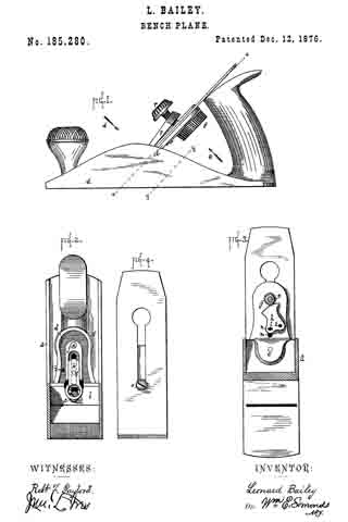
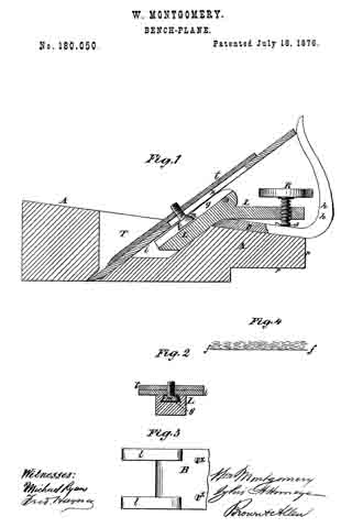
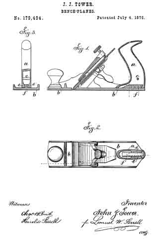
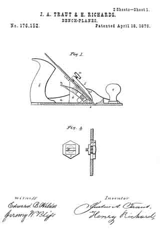
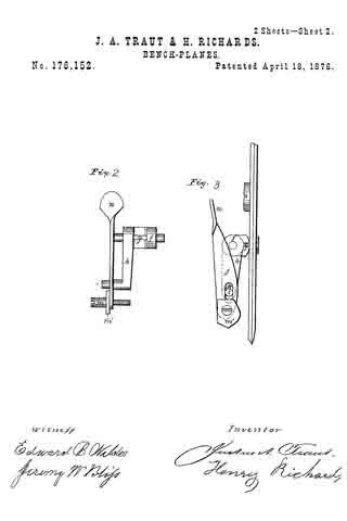
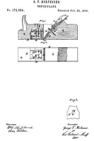
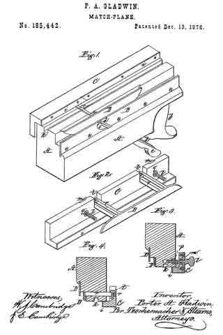
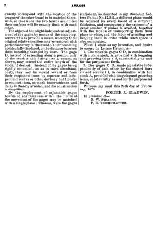
Figure 1 is a perspective view of my match-plane inverted. Fig. 2 is a perspective view of the two movable gages connected together and detached from the plane. Figs. 3 and 4 are transverse vertical sections.

My present invention relates to certain improvements in match-planes for which Letters Patent of the United States No. 17,541 were granted to me June 9, 1857.

The stock of the plane referred to was constructed so as to receive and hold a double iron-one portion for tonguing and the other for grooving–two stationary gages being employed in connection with this double iron; but on account of these gages being stationary only one thickness of material could be matched with a single plane, and consequently a number of these tools were required to match boards of different thicknesses.

My invention has for its object to provide a single match-plane, which can be so adjusted as to adapt it for boards of various thicknesses; and consists in a pair of movable gages, in combination with a stock provided with both a tonguing and a grooving iron.

My invention also consists in so connecting or coupling these gages that they may be moved simultaneously in the same direction, in order thereby to insure the perfect matching of two boards of the same thickness.

My invention furthermore consists. in making one of the gages adjustable independently of the other, in order that the relative position of one gage may be slightly changed with respect to that of the other, whereby the tongue and groove may be so located that the surfaces of the two boards to be matched will lie flush with each other.

To enable others skilled in the art to understand and use my invention, I will proceed to l describe the manner in which I have carried it out.

In the said drawings, A represents the stock of my improved plane, which is provided with a handle, b, its bottom being of the form seen. In the throat of the stock is secured, by means of a wedge, a double-edged tonguing-iron, c, a double-edged grooving-iron, d, being also secured within the stock by a wedge, e, a throat, 5, being formed in a plate, B, screwed to one side of the stock, through which the iron d passes.

On the bottom of the stock A, opposite to that to which the plate B is screwed, slides a longitudinal gage, G, of L shape in cross-section, and provided with a metal facing, i, the distance of which from the edge of the groove k in the stock A is regulated by two thumb-screws, l l, which pass through plates m m, let into the side of the gage, and enter nuts p, set into the stock A, as seen in Fig. 3, each screw being held in place within the gage by a collar, q; and by means of these screws the position of the gage with respect to the groove in the tonguing-iron c may be varied as desired for boards of different thickness.

The part of the plane which cuts the groove is provided with a movable gage, D, by which the distance of the groove from the edge of the board may be varied according to its thickness. This gage D consists of a plate, which is connected or coupled with the tonguing-gage C by two slotted bars, r r, passing through the stock, the bars r r, which project from the side of the gage D, being secured to the gage C by screws t, which admit of the distance between the gages being slightly varied, as desired; and when these screws are clamped or tightened the gages are rigidly coupled or secured together, so as to move simultaneously in the same direction when operated by the thumb-screws l l. By rigidly connecting the two gages C D, so that they will move in common, the distance of the gage C from the nearest edge of the groove in the tonguing-iron c will be exactly equal to the distance of the gage D from the side of the grooving-iron d nearest to it, by which means the location of the groove in one board will exactly correspond with the location of the tongue of the other board to be matched therewith, so that when the two boards are united their surfaces will lie exactly flush with each other.

The object of the slight independent adjustment of the gages by means of the clamping-screws t t to provide a means whereby their original relative position may be restored with perfect accuracy in the event of their becoming accidentally displaced, or the distance between them becoming changed by wear. The gage D, instead of extending along a portion only of the stock A and fitting into a recess, as shown, may extend the entire length of the stock, if desired. Instead of the gages being rigidly connected, so as to move simultaneously, they may be moved toward or from their respective irons by separate and independent screws or other devices; but I prefer to connect them, as much inconvenience and delay is thereby avoided, and the construction is simplified.

By the employment of adjustable gages boards of any thickness within the limits of the movement of the gages may be matched with a single plane; whereas, were the gages stationary, as described in my aforesaid Letters Patent No. 17,541, a different plane would be required for every board of a different thickness, and consequently the expense of a great number of planes is avoided, together with the trouble of transporting them from place to place, and the labor of grinding and keeping them in order while much space is also economized.

What I claim as my invention, and desire to secure by Letters Patent, is —

1. The movable gages C D, in combination with a plane-stock, A, provided with tonguing and grooving irons c d, substantially as and for the purpose set forth.

2. The gages C D, made adjustable independently of each other by the slotted bars r r and screws t t, in combination with the stock A, provided with tonguing and grooving irons, substantially as and for the purpose set forth.

Witness my hand this 24th day of February, 1876.

PORTER A. GLADWIN.

In presence of —
N. W. STEARNS,
P. E. TESCHEMACHER.

No. 185,280 – Improvement In Bench-Planes (Leonard Bailey) (1876)

[paiddownloads id=”272″]185280


UNITED STATES PATENT OFFICE.

_________________

LEONARD BAILEY, OF HARTFORD, CONNECTICUT.

IMPROVEMENT IN BENCH-PLANES.

_________________

Specification forming part of Letters Patent No. 185,280, dated December 12, 1876; application filed August 31, 1876.

_________________

To all whom it may concern:

Be it known that I, LEONARD BAILEY, of Hartford, in the county of Hartford and State of Connecticut, have invented an Improvement in Bench-Planes, of which the following is a specification, reference being had to the accompanying drawings, where —

Figure 1 is a side view of a plane bearing my improvements. Fig. 2 is a cross-section on plane x x, looking rearward, as denoted by arrow A, with the plane-irons and fastening cap removed. Fig. 3 is a cross-section on plane y’ y’, looking forward, as denoted by arrow B, with the operating-disk removed. Fig. 4 is a detail view of the rear side of the plane-irons.

The invention is an apparatus or attachment for moving the iron or chisel up and down within limits — that is, for adjusting the chisel.

The letter a denotes the body of an iron plane; b, the bed for the chisel, to the back of which, by screw c, is fastened the bed-elongation d. On shaft-pin e, which projects from the back side of elongation d, is hung, rotarily, the operating-disk f, by which I mean, the disk operated by the user in order to adjust the chisel. On the same shaft-pin, and rigid with the disk f is hung the pinion g, meshing into the gear-segment h, hung on the pin i, projecting from the back of elongation d. In groove i, made in the front side of elongation d, lies and travels the slide k, and a pin, l, projecting rigidly from its back, runs through the mortise m in elongation d, and through the slot n in gear-segment h.

The head of screw o, which holds the two chisels together, lies in the round hole at the lower end of slide k, so that, when the chisels are in place, they and the slide must move together. By rotating the disk f one way or the other, the pinion g and gear segment h are correspondingly rotated, and the pin l, and with it the slide k and irons or chisels, moved up or down correspondingly. When adjusted, the chisels are held to plane in a common manner by means of fastening-cap p and screw v.

I claim as my invention —

1. In combination, bed-elongation d, disk and pinion f g, gear-segment h, and pin l, all substantially as and for the purpose set forth.

2. In combination, disk and pinion f g, gear-segment h, and slide k, all substantially as and for the purpose set forth.

LEONARD BAILEY.

Witnesses:
M. F. DOOLEY,
ROBT. F. GAYLORD.

No. 184,241 – Improvement In Plane-Guides (William H. Harris And Milo Harris) (1876)

[paiddownloads id=”271″]184241


UNITED STATES PATENT OFFICE.

_________________

WILLIAM H. HARRIS AND MILO HARRIS, OF JAMESTOWN, N. Y.

IMPROVEMENT IN PLANE-GUIDES.

_________________

Specification forming part of Letters Patent No. 184,241, dated November 14, 1876; application filed July 3, 1876.

_________________

To all whom it may concern:

Be it known that we, WM. H. HARRIS and MILO HARRIS, of Jamestown, in the county of Chautauqua and State of New York, have invented certain new and useful Improvements in Plane Guides; and we do hereby declare that the following is a full, clear, and exact description thereof, which will enable others skilled in the art to which it appertains to make and use the same, reference being had to the accompanying drawings, and to the letters of reference marked thereon, which form a part of this specification.

The object of our invention is to furnish a cheap and simple guide for bench-planes, so as to plane or saw any desired bevel; and the nature of the invention consists in the combination of devices employed, as hereinafter more fully set forth.

Figure 1 is a view of the guide, with a protractor and end plate attached to each end. Fig. 2 is a view of the metal plate attached to the end of a plane. Fig. 3 is a side view of the plane and guide, with end plate and protractor attached. Fig. 4 is a view of our invention as applied to a saw-table.

ln the drawings, A represents a semicircular bevel-protractor, made of suitable metal, and having a long circular slot near its center, through which the bolt or screw D passes to secure it firmly to the end plate B, and also a semicircular stud, x, at its lower edge, that turns in the semicircular indentures c c c, and also a lip turned at right angles with its surface, through which screws pass to securely fasten it to the guide C. B is a metal plate, that is securely fastened to the end of a plane, as shown in Fig. 2, and having screw-holes for this purpose, and holes a a a, with a screw-thread cut in them to receive the bolt D. It has also sernicircular indentures c c c in its lower edge to receive the stud x of the bevel-protractor. One of these plates, with the bevel-protractor, is fastened at each end of the plane, and, having the guide C attached, is shown in Figs. 1 and 2. The object of having so many places for the bolt D is that by so doing we can use any part of the face of the plane, and by changing ends with the guide C it will work on the back part of the plane-face, thus enabling us to bevel either edge of the board. The object of indentures c c c and stud x is to form a center for the bevel-protractor to turn on, in order that the corner of the guide C will always retain its relative position with the face of the plane, and as the bolt-holes a a a are placed at an angle of forty-five degrees with the indentures c c c we do not have to use but three indentures c c c for all the bolt-holes, no matter on which side of the plane-face the gage is used.

The plate B may be made with a long slot through its center, and a movable nut to receive the bolt D, or said plate may be made dovetailing, and inserted in a movable plate on which the bevel-protractor moves across the plane; but we prefer the manner shown in the drawings, as it is cheaper and more secure.

By means of the semicircular stud x in the bevel protractor A, and the indentures c c c in the metal plate B, the guide C can be moved to any part of the face of the plane, and the inner corner of said guideis held in the exact center of the circle described by the bevel-protractor A, and the guide is kept close to the face of the plane at any angle it maybe turned without any further adjustment, and by turning the lip d parallel with the face of the plane a much thinner guide can be used and thinner lumber planed without coming in contact with the work-bench.

We claim —

The combination of the bevel-protractor A, having stud x and lip d, with the end plate B, provided with the semicircular indentations c c c, the screw-bolt D, and the guide C, all constructed to operate as shown and described, and for the purpose specified.

In testimony that we claim the foregoing as our own invention we affix our signatures in presence of two witnesses.

WM. H. HARRIS.
MILO HARRIS.

Witnesses:
J. E. GOULD,
J. E. HARRIS.

No. 182,881 – Improvement In Box-Scrapers (Leonard Bailey) (1876)

[paiddownloads id=”270″]182881


UNITED STATES PATENT OFFICE.

_________________

LEONARD BAILEY, OF HARTFORD, CONNECTICUT.

IMPROVEMENT IN BOX-SCRAPERS.

_________________

Specification forming part of Letters Patent No. 182,881, dated October 3, 1876; application filed September 13, 1876.

_________________

To all whom it may concern:

Be it known that I, LEONARD BAILEY, of Hartford, in the county of Hartford and State of Connecticut, have invented certain new and useful Improvements pertaining to a Box-Scraper, of which the following is a specification, reference being had to the accompanying drawings, where —

Figure 1 is a side view. Fig. 2 is a top view. Fig. 3 is a bottom view. Fig. 4 is a top view, chisel removed. Fig. 5 is a central section on plane x x, Fig. 2, chisel removed.

The letter a denotes a forked handle, whereby to move the scraper back and forth. b denotes a rod, which is at once a pivot-bar for head c and a front rest for chisel d. The back side of the pivoted head c is obliqued, to form a bed for the chisel, which chisel is held in place by thumb-screw e running up through the bed elongation c’ from the back side, and bearing against the back side of the chisel.

The throat f may be made larger or smaller, and the out of the chisel correspondingly increased or decreased by manipulation of the guard or gage i, pivoted by its side arms i1 on the rod b, given a closing tendency by the spring-bar i2, and opened against this tendency by the thumb-screw g.

The features of invention, specified in the first two clauses of the following claim, are applicable as well to spokeshaves as to box-scrapers.

I claim as my invention —

1. In combination, head c, having bed elongation c’, chisel d, front rest b, and thumb-screw e passing through the bed elongation and pressing on the back side of the chisel, all substantially as shown and described.

2. In combination, bar b, head c, chisel d, guard or gage i pivoted on bar b, spring-bar i2, and screw g, all substantially as shown and described.

3. In combination, forked handle a, bar b, serving as pivot for head c and front rest for chisel d, pivoted head c having elongation c’, and screw e, all substantially as shown and described.

LEONARD BAILEY.

Witnesses:
ROBT. F. GAYLORD,
CHAS. BUCKLAND.

No. 182,722 – Improvement In Plane-Guides (Andrew J. Teamer) (1876)

[paiddownloads id=”269″]182722


UNITED STATES PATENT OFFICE.

_________________

ANDREW J. TEAMER, OF EVANSVILLE, INDIANA.

IMPROVEMENT IN PLANE-GUIDES.

_________________

Specification forming part of Letters Patent No. 182,722, dated September 26, 1876; application filed June 12, 1876.

_________________

To all whom it may concern:

Be it known that I, ANDREW J. TEAMER, of Evansville, Indiana, have invented certain Improvements in Plane-Guides, of which the following is a specification:

My invention relates to certain improvements in that class of planes in which an adjustable guide hung to the plane is used for determining the angle of the cut to be made by the plane-bit; and the object of my improvements is to so construct a plane of this class that the guide can be readily adjusted to any desired angle. This object l attain in the manner which I will now proceed to describe, reference being had to the accompanying drawing, in which —

Figure 1 is a side view of my improved plane and guide, and Fig. 2 a transverse vertical section of the same.

A is the plane, and B the guide, the latter being secured near each end by means of set-screws a to plates D, each of which has a projection, b, hinged by a bolt or pin, d, to ears e on a plate, F, the latter being secured by means of set-screws f to the side of the plane.

The set-screws a and f, are adapted to vertical slots g in the plates D and F, and each of these slots terminates at its upper end in an opening, i, larger in diameter than the head of the set-screw.

Each of the bolts d, by which the guide B is hung to the plane, is provided with a nut, m, on tightening which the guide may be secured to any angle in respect to the plane to which it may be adjusted. In order that this angle may be accurately determined, I make the projection b of one of the plates D of the segmental form shown in Fig. 2, and on the periphery of this segment make lettered or numbered graduations, a mark, x, on one of the ears to which the projection is hinged, indicating the angle at which the guide B is set in respect to the plane, and the bevel of the edge of the strip which is being operated upon.

In addition to the angular adjustment of the guide B, the latter may, owing to the slots g in the plate F and plates D, be adjusted vertically in respect to the plane, and, owing to the enlarged openings i at the ends of the slots, the plate F may be readily removed from one plane and attached to another, or the guide B may be removed and replaced by a new one. Instead of using a bolt, d, and nut m for clamping the plates D and F, together, as described, a screw-bolt, adapted to a thread out in one of the ears e, may be used.

It will be seen that these bolts answer the twofold purpose of hinging the two plates together, and of securing them in position after adjustment, thus avoiding the necessity of employing a separate thumb-screw in addition to the hinging-pin, as is usual.

It will be evident also that plates similar to the plates D may be substituted for the plate F, and that a plate, F, may be applied to the guide, but the construction shown is preferred.

I wish it to be understood that I do not desire to claim, broadly, a plane-guide hinged to a plane by means of adjustable plates; but I claim as my invention —

1. The combination of the hinging and clamping bolts d with the plane A and plate F, having ears e e, and with the guide B and plates D, having projection b, all substantially as described.

2. The plates D, having slots g, with enlarged openings i, in combination with the guide B and its set-screw a.

3. The combination of the guide B and the plates D, having a graduated segmental projection, b, with the plane A and the plate F, having ears e e, as and for the purpose set forth.

In testimony whereof I have signed my name to this specification in the presence of two subscribing witnesses.

ANDREW JACKSON TEAMER.

Witnesses:
JOHN BRIGGS,
A. C. ANCONA.

No. 182,320 – Improvement In Spokeshaves (George D. Mosher) (1876)

[paiddownloads id=”268″]182320


UNITED STATES PATENT OFFICE.

_________________

GEORGE D. MOSHER, OF NEW BRITAIN, CONNECTICUT.

IMPROVEMENT IN SPOKESHAVES.

_________________

Specification forming part of Letters Patent No. 182,320, dated September 19, 1876; application filed August 24, 1876.

_________________

To all whom it may concern:

Be it known that I, GEORGE D. MOSHER, of New Britain, in the county of Hartford and State of Connecticut, have invented certain new and useful Improvements pertaining to Spokeshaves, of which the following is a specification, reference being had to the accompanying drawings, where —

Figure 1 is a front view. Fig. 2 is a rear view. Fig. 3 is a sectional view on plane x x. Fig. 4 is a detail fron view of the clamp. Fig. 5 is a top view of same.

The letter a denotes the body of the spoke shave, mortised centrally for the passage of the knife b, which lies on the bed c. From the body a rises the standard d, and its front face is a prolongation of the knife-bed c. The knife is held to place by the clamp e, having a loop, e’, the loop of running around the back of the standard d. A set-screw, f runs through the front of clamp e, and bears on the knife.

The novelty consists in the means just described for holding the knife in place; and the same ideas are applicable to planes and box-scrapers.

I claim as my invention —

The combination of the knife b, the clamp e, having the loop e’, and the standard d, all substantially as described, and for the purpose set forth.

GEORGE D. MOSHER.

Witnesses:
WILLIAM H. MAIN,
CHAUNCEY BECKWITH.

No. 181,649 – Improvement In Plane-Irons (Henry Disston) (1876)

[paiddownloads id=”267″]181649


UNITED STATES PATENT OFFICE.

_________________

HENRY DISSTON, OF PHILADELPHIA, PENNSYLVANIA.

IMPROVEMENT IN PLANE-IRONS.

_________________

Specification forming part of Letters Patent No. 181,649, dated August 29, 1876; application filed April 29, 1876.

_________________

To all whom it may concern:

Be it known that I, HENRY DISSTON, of Philadelphia, Pennsylvania, have invented certain Improvements in Plane-Irons, of which the following is a specification:

The object of my invention is to so construct a plane-bit that it may be more readily and truly ground and sharpened than ordinary edge-tools of this class, a further object of my invention being economy in the consumption of material in making the tools.

In the accompanying drawing, Figure 1 represents a front view of a plane-bit made according to my invention; Fig. 2, a section on the line 1 2; Fig. 3, a transverse section on the line 3 4; Fig. 4, a modification of Fig. 3.

The plane-bit A (shown in Figs. 1, 2, and 3) has a series of parallel grooves or indentations, a, on that side from which the tool is beveled to a sharp edge, the grooves being of such a depth that they will extend into the beveled portion d, as shown. With the exception of these grooves or indentations the plane bit is similar to those of ordinary construction; and, as it is no thicker than usual, the ribs between the grooves impart the desired rigidity, While less material is consumed an its manufacture than in making common bits.

The grinding of the beveled edge of a bit thus constructed can be more readily accomplished than that of an ordinary bit, for the reason that there is less metal to remove, and it is much easier to grind truly an indented surface than one without grooves, as will be readily understood by those familiar with grinding operations.

The plane-bit can be readily manufactured by means of two dies, one being flat, for the flat face of the bit, the other having ribs corresponding with the desired indentations, and the two dies being used in connection with any ordinary drop press.

It is not essential that the indentations or grooves and intervening ribs should be of the precise shape shown in the sectional view, Fig. 3. They may, for instance, be of the form shown in Fig. 4, with good results as regards the facility of grinding, sharpening, and economizing of material.

I claim as my invention —

As a new article of manufacture, a plane-bit having grooves or indentations on its beveled side, as specified.

In testimony whereof I have signed my name to this speciiication in the presence of two subscribing witnesses.

HENRY DISSTON.

Witnesses:
A. H. SHOEMAKER,
GEO. S. GAUDY.

No. 180,867 – Improvement In Bench-Planes (Jackson Gorham) (1876)

[paiddownloads id=”266″]180867


UNITED STATES PATENT OFFICE.

_________________

JACKSON GORHAM, OF CRAWFORDVILLE, GEORGIA, ASSIGNOR TO HIMSELF AND CHARLES E. SMITH, OF SAME PLACE.

IMPROVEMENT IN BENCH-PLANES.

_________________

Specification forming part of Letters Patent No. 180,867, dated August 8, 1876; application filed July 11, 1876.

_________________

To all whom it may concern:

Be it known that I, JACKSON GORHAM, of Crawfordville, in the county of Taliaferro and State of Georgia, have invented an Improvement in Bench-Planes, of which the following is a specification:

My invention consists of a stud applied on the top of a smoothing-plane stock near the heel, and adapted to fit between the thumb and forefinger of the right hand, while the palm bears against the heel of the stock, whereby the pressure of the hand is distributed over a larger surface, and is thus diminished on the small area heretofore employed for driving the plane by pressing against the heel of the stock. It also affords a bearing or rest for a part of the hand not heretofore having any support on the stock, and therefore making the work easier.

The drawing is a perspective side elevation of a plane-stock constructed according to my invention.

A is the stock, and B the stud, which I apply as above described. The rear side of the stud a is made in suitable transverse convex; form and vertical concave form, to make an easy bearing for the hand. The handle may be made separate from the stock and attached to it, or it may be worked out of the block in connection with it.

Having thus described my invention, what I claim as new, and desire to secure by Letters Patent, is —

The plane-stock A, having the stud B, constructed in the form represented at a, and located relatively to the heel of the stock, substantially as specified.

JACKSON GORHAM.

Witnesses:
V. T. SMITH,
CHARLES A. BEAZLEY.

No. 180,050 – Improvement In Bench-Planes (William Montgomery) (1876)

[paiddownloads id=”265″]180050


UNITED STATES PATENT OFFICE.

_________________

WILLIAM MONTGOMERY, OF AMITY, PENNSYLVANIA.

IMPROVEMENT IN BENCH-PLANES.

_________________

Specification forming part of Letters Patent No. 180,050, dated July 18, 1876; application filed April 27, 1876.

_________________

To all whom it may concern:

Be it known that I, WILLIAM MONTGOMERY, of Amity, in the county of Washington and State of Pennstylvania, have invented Improvements in Bench-Planes; and I do hereby declare that the following is a full, clear, and exact description of the same, reference being had to the accompanying drawing, which forms part of this specification.

My invention relates to a new combination of devices for adjusting and clamping the blade or plane iron in the stock of the plane; and it consists in the combination of devices employed as hereinafter more fully set forth.

Figure 1 in the accompanying drawing, represents a vertical longitudinal section through my improved plane. Fig. 2 is a section through the plane irons and attachments thereof on the line x x. Fig. 3 is a top view of the bed-plate, to which the clamping-lever, which secures the irons in the plane-stock, is pivoted. Fig. 4 is a diagram illustrating the manner in which the grain of the wood runs in relation to the face of the plane.

A is the stock, which may be made of wood or metal. The said stock is thinner, measured vertically, at the rear end or heel than at the forward end, and at the rear end the stock is provided with a projection, p, which supports inpart the handle n. In cutting the plane-stock to the wedge form the grain of the wood is cut obliquely across, as shown in Fig. 4, in which the dotted lines represent the grain of the wood, and the line f f represents the face of the plane. The bed-plate B, shown in Fig. 3, and in section in Fig. 1, is attached to the top of the plane-stock A, at the back of the throat T of said stock, the attachment being made by screws x. The bed-plate B has at its front end lugs l, Fig. 3, to which is pivoted, by a screw-bolt, or in any other suitable manner, the bent lever L, the said bed-plate being cut away between the said lugs to make room for said lever L, and the tops of said lugs being rounded off, to allow the plane-irons i t to retreat far enough at the top to allow the insertion of a wedge under them at the bottom. The front part of the lever L passes down into the throat T of the plane, a recess, r, being formed in the back of said throat for the reception of the said front part of said lever, and the rear part of said lever passes backward over the top of the bed-plate, at the rear of the said throat T. In the rear part of said lever is fitted a thumb-screw, R, and in the front part of said lever is formed a dovetail-groove, g, shown in section in Fig. 2.

The head of the screw m, which holds the top iron on the cutting-iron of the plane, is made in the form of a frustum of a cone, and of dimensions to adapt it to the dovetail groove g in the front part of the lever L. The point of the thumb-screw R rests in a notched saddle, S, either on the handle h, the bed-plate B, or the plane-stock A, in various kinds of planes, and the said screw may fit a female screw in the rear end of the lever L, or it may fit the thread of a nut swiveled to the said lever. The half-handle h is formed in one piece with the bed-plate B, as shown in Fig. 1, when the plane-stock A is made of wood; but when the plane-stock is made of metal the bed-plate B may be dispensed with, and the lugs l of the same, and the handle h, may be cast in one piece with said stock. And when a jack-handle is used, it is attached to the stock, and not to the bed-plate B. Also, in long-faced planes the projection p, which supports the rear of the handle in short-faced planes, is omitted, there being space enough for the support of said handle without the projection. The cutting iron i and top iron t are fitted into the throat, as shown in Fig. 1, the top iron being held upon the cutting-iron by the screw m, which passes through the slot n, in the cutting-iron, and screws into the top iron in the usual manner.

The adjustment and clamping of the irons i and t are performed as follows: The top iron t is placed in its proper position on the cutting-iron i, and is fastened there by the screw m. The irons are then placed in the throat T of the stock A, the head of the screw in passing down into the groove g of the lever L. The screw R is then turned down, and, its point being prevented from advancing, the hinder part of the lever L is forced upward. This forces the lower part of the lever L downward and rearward, and draws backward and downward the screw m, the head of which is engaged in the groove g of the said lever, and the opposite end of which is engaged in the female screw of the top iron, t. The plane-irons are thus firmly pressed against the lower part of the throat of the plane-stock, and that part of the lever L in front of the pivot of said lever, which pressure securely clamps the irons in the plane-stock.

The head of the screw m might be made of proper form to engage a groove of rectangular cross-section in the lower part of the lever L; but I prefer the dovetail groove and the corresponding shape of head for the said screw, because this form gives a wedging action, which holds the irons powerfully without excessive strain on the thumb-screw R.

A cheap, easy-running, and durable plane is thus produced, in which the handle is brought down nearer the work than in planes heretofore used, and hence the muscular power of the operator is more efficiently applied.

I claim —

The combination of the stock A, having projection p, with the pivoted lever L, provided with a dovetail groove in its face, adjusting-screw R, notched saddle S, bed-plate and handle B h, and screw m, all constructed to operate as shown and described, and for the purpose specified.

WILLIAM MONTGOMERY.

Witnesses:
B. F. MONTGOMERY,
JAMES B. MONTGOMERY.

No. 179,494 – Improvement In Bench-Planes (John J. Tower) (1876)

[paiddownloads id=”264″]179494


UNITED STATES PATENT OFFICE.

_________________

JOHN J. TOWER, OF BROOKLYN, NEW YORK.

IMPROVEMENT IN BENCH-PLANES.

_________________

Specification forming part of Letters Patent No. 179,494, dated July 4, 1876; application filed May 29, 1876.

_________________

To all whom it may concern:

Be it known that I, JOHN J. TOWER, of Brooklyn, in the county of Kings and State of New York, have invented an Improvement in Metal Plane-Handles, of which the following is a specification:

Metal planes have heretofore been constructed with handles of wood, and also with globular knobs at the forward end of the plane.

My improvement relates to a hollow cast-metal handle, secured to the plane by dove-tailed projections, so that the connection is very strong and durable, and at the same time the handle is very light, and of a size and shape to be grasped by the hand.

The handle is represented in the drawing by a vertical seetion, Figure 1, horizontal section, Fig. 2, and cross-section, Fig. 3.

The handle a is of cast metal, preferably of iron. It is made hollow, so as to be as light as possible and maintain the requisite strength. The general shape of this handle is similar to those made of wood, and hence it is as convenient in use. In order to strengthen the lower part of the handle, and prevent the same being bent by the attachment to the plate b of the plane, I introduce the cross-bar c, cast with the rest of the handle. Dovetails that taper slightly are employed for fastening the base of the handle to the plane-stock. These dovetails are made by lips inside the base of the handle, as seen at e. The dove-tail block f upon the plane-stock b is shorter than the base of the plane-handle a, and the dovetail portions e do not extend the whole distance along the inner edges of the handle, so that the handle a can be put over the dove-tail-block f by slipping it from the back forward, and keeping the back edge down, in order that the handle may receive the dove-tail-block, and the parts tapering, the handle may be secured firmly by driving it forward upon the dovetail block. By this construction it is not necessary to have any opening at the forward part of the base of the handle, as such base sets down flat upon the plane-stock, and makes a neat, handsome, and durable connection, the dovetail not being visible.

This hollow cast-iron plane-handle may be plated or otherwise finished, and as the handle extends to the upper surface of the bottom of the plane, the hand of the operator can be as near to the surface of the wood as possible, so that the power can be exerted to good advantage.

I do not claim a plane with a hollow knob or handle with dovetail projections for holding the plane-iron to the stock, as this has been used; neither do I claim a hollow metal plane-handle.

I claim as my invention —

The metallic plane-handle cast hollow, with a cross-bar, c, and dovetail lips e extending a part of the distance along the inner portion of the base, in combination with the dovetail block f upon the stock of the plane, substantially as set forth.

Signed by me this 22d day of May, A. D. 1876.

JOHN J. TOWER.

Witnesses:
GEO. T. PINCKNEY,
CHAS. H. SMITH.

No. 178,256 – Improvement In Carpenters’ Planes (Samuel Williams) (1876)

[paiddownloads id=”263″]178256


UNITED STATES PATENT OFFICE.

_________________

SAMUEL WILLIAMS, OF COLUMBUS, OHIO.

IMPROVEMENT IN CARPENTERS’ PLANES.

_________________

Specification forming part of Letters Patent No. 178,256, dated June 6, 1876; application filed March 15, 1876.

_________________

To all whom it may concern:

Be it known that I, SAMUEL WILLIAMS, of Columbus, in the county of Franklin and State of Ohio, have invented certain new and useful Improvements in Carpenters’ Planes; and I do hereby declare that the following is a full, clear, and exact description thereof, which will enable others skilled in the art to which it appertains to make and use the same, reference being had to the accompanying drawings, and to the letters of reference marked thereon, which form a part of this specification.

In the accompanying drawings, Figure 1 is a side elevation of a plane with my improvement attached thereto. Fig. 2 is a vertical transverse section of the same on the line x x, Fig. 1. Fig. 3 is an end view, showing the motion of the guide in dotted line. Fig. 4 is a full-sized view of the clutch-bolt and thumb-screw. Fig. 5 shows a detached modification.

My invention consists of certain novel combinations and arrangements of devices for a simple and efficient bevel-guide for planes, the details of which will be fully understood by the following description:

ln the accompanying drawings, A is a plane-stock, with a groove, B, out in each side, to receive the adjustable slide C, which is cast in the same piece with the male part F of the hinge. This slide has a rib, c, which fits the groove B of the plane, in order to prevent the slide from swinging, and thus throwing the bevel-guide out of place. The guide D is attached to the hinge-piece E, which is very strong, and has a slot with broad bearing-sun faces, to grasp the male part F of the hinge, and hold the same firmly in place. This hinge has a central pivot, G, and a set-screw, H, which passes through the curved slot I, Fig. 2, in order to adjust the bevel-guide to any desired angle. A clutch-bolt, K, passes through the plane-stock A, as shown in Fig. 4, and has one end provided with the clutch K’, to grasp the slide C, while the other end is provided with a thumb-screw or nut, L, and washer, M, for fastening the guide to the plane.

The hinge may be graduated in an arc, so as to set the guide D at any desired angle, as is well understood.

Instead of the clutch- bolt K, an arched plate, N, with a set-screw, O, may be used; but I prefer the clutch-bolt shown in Fig. 4.

If necessary with long planes, two clutch-bolts and two hinges may be used to hold the guide more securely in place.

This guide is very simple, and yet strong and durable, and it is very convenient of adjustment, and may be easily changed from one side of the plane to the other, and thus enable the workman to plane cross-grained stuff, and also prevent the uneven wear of the bit.

Having thus described my invention, I claim —

The slide C, provided with the rib c, in combination with the bolt K, bevel-guide D, and plane-stock A, substantially as and for the purposes set forth.

In testimony that I claim the foregoing as my own I affix my signature in presence of two witnesses.

SAML. WILLIAMS.

Witnesses:
DANIEL BREED,
S. E. CARPENTER.

No. 176,152 – Improvement In Bench-Planes (Justus A. Traut And Henry Richards) (1876)

[paiddownloads id=”262″]176152


UNITED STATES PATENT OFFICE.

_________________

JUSTUS A. TRAUT AND HENRY RICHARDS, OF NEW BRITAIN, CONNECTICUT.

IMPROVEMENT IN BENCH-PLANES.

_________________

Specification forming part of Letters Patent No. 176,152, dated April 18, 1876; application filed December 27, 1875.

_________________

To all whom it may concern:

Be it known that we, JUSTUS A. TRAUT and HENRY RICHARDS, of New Britain, county of Hartford and State of Connecticut, have invented a certain new and useful Improvement in Bench-Planes; and to enable others skilled in the art to make and use the same, we will proceed to describe it, referring to the drawings, in which the saine letters indicate like parts in each of the figures.

The nature of this invention consists in the device for holding and adjusting the cutting-iron.

In the accompanying drawings, Figure 1 is a side view of a plane, having one side portion of the stock removed to show the incline brackets, upon which the cutting-iron is held, and the compound levers for adjusting the irons. Fig. 2 is a top view of the compound levers detached from the stock. Fig. 3 is a side view of the compound levers detached from the stock. Fig. 4 is an enlarged view of the adjustable stud by means of which the cut of the iron is regulated through the mouth of the plane by means of the compound levers and the rocking spindle.

The object of this invention is to cheapen the manufacture, and produce a simple, sure, and effective mode of adjusting and holding the irons in the desired condition.

a is the stock. b is the handle; c, the knob for steadying the plane. S is a fastening-pad, which bears upon the lower end or face of the iron, and takes bearings on the upper side against the pins t t, and is provided with a thumb-screw, u, by means of which the iron, when adjusted, is held firmly in place. This fastening-pad and all above described are now in common use. d represents inclined brackets, arranged a short distance apart each way from the center of the stock, and in diverging lines back from the mouth e of the plane, and form bearings for the cutting-irons. f is a rocking spindle, having a groove, g, and a lever, h. This rocking spindle with its lever it is secured by fulcrum-bearings between and near the upper end of the brackets d, while the wrist-pin i in the lower end of the lever h vibrates in an opening in one of the brackets d. j is a thumb-lever, having near its lower end an opening to receive the pin i, which is secured near the lower end of one of the brackets d by a screw, m, and with or without a friction-collar, m’, so that by raising or depressing the lever j by a thumb-pad, n, the required vibration or rotation of the rocking spindle having the groove g will be produced, to cause the movement of the iron up or down. o is a stud, having a tooth projection, o’, fitted to, and working in, the groove of the rocking spindle f This stud o is fitted to play in an opening, p, formed in the cutting-iron or cap-plate, so as to allow it to be adjusted to its proper position, and then secured by a nut, r. Thus it will be seen that by the use of the adjustable stud o its tooth can be readily adjusted, and firmly secured to a single or double iron from time to time, as it becomes worn or ground off from its cutting end, and when the tooth o’ is placed in the groove g of the rocking spindle f by the action of the compound levers h j up and down, the cutting-iron can be easily and accurately adjusted and firmly secured by the fastening-pad S in the common way.

What we claim, and desire to secure by Letters Patent, is —

The combination of the levers h j, rocking spindle f, having groove g and brackets d, with the stud o, having the tooth projection o’, substantially as shown and described.

JUSTUS A. TRAUT. [L. S.] HENRY RICHARDS. [L. S.]

Witnesses:
EDWARD B. WILDER,
JEREMY W. BLISS.

No. 176,151 – Improvement In Spokeshaves (Justus A. Traut And Henry Richards) (1876)

[paiddownloads id=”261″]176151


UNITED STATES PATENT OFFICE.

_________________

JUSTUS A. TRAUT AND HENRY RICHARDS, OF NEW BRITAIN, CONNECTICUT.

IMPROVEMENT IN SPOKESHAVES.

_________________

Specification forming part of Letters Patent No. 176,151, dated April 18, 1876; application filed January 24, 1876.

_________________

To all whom it may concern:

Be it known that we, JUSTUS A. TRAUT and HENRY RICHARDS, of New Britain, county of Hartford, and State of Connecticut, have jointly invented certain new and useful Improvements in Spokeshaves; and to enable others skilled in the art to make the same, we will proceed to describe it, referring to the drawings, in which the same letters of reference refer to like parts in each of the figures.

Our invention consists in forming the stock of a spokeshave in a V shape, and with a cutting-iron in each of the faces, in order that it may be used to cut to or from the operator without the need of reversing it. Also, in the peculiar means of fastening and adjusting the irons, as will be hereinafter more fully shown.

In the accompanying drawings, Figure 1 is a plan view of our invention. Fig. 2 is an edge view. Fig. 3 is a cross-section through the compression dogs and screws. Fig. 4 is a cross-section of the handle.

Similar letters of reference indicate similar parts.

a is the stock, having its cross-section in a V shape, so as to form two working faces. In each face is formed a longitudinal slot, m, through which projects the bit b. The interior of the stock is also conical shaped, so as to form two beds for the bits and hold them at a proper cutting-angle. In order to make a more perfect adjustment of the cutting-irons, they should be beveled on the upper side. c c are compression-dogs, corresponding in shape to the interior of the stock a, so as to bear against the face of the bits. Through the dogs c c are formed orifices d d for the reception of thumb screws h h. These orifices are enlarged in their upper portion, so as to form a shoulder, upon which rests a coil-spring, f through which the thumb-screws pass into screw-threaded orifices i i, formed in the stock directly under the dogs c c. One end of these springs bears against the screw-head, and the other against the shoulder or bottom of the spring-chamber, so that they serve before the screws are tightened to sufficiently compress the dogs against the bits, and thus allow of their adjustment, and remove liability to fall out or be misplaced. The handles are curved upward, and made concave underneath and convex on the upper side.

Having described its construction, what we claim, and desire to secure by Letters Patent, is —

The combination, in a spokeshave, of the stock a, having two faces, cutting-irons b, dogs c c, and clamping set-screws h h, substantially as shown and described.

JUSTUS A. TRAUT. [L. S.] HENRY RICHARDS. [L. S.]

Witnesses:
EDWARD B. WILDER,
JEREMY W. BLISS.

No. 175,758 – Improvement In Box-Scrapers (Henry Richards And Justus A. Traut) (1876)

[paiddownloads id=”260″]175758


UNITED STATES PATENT OFFICE.

_________________

HENRY RICHARDS AND JUSTUS A. TRAUT, OF NEW BRITAIN, CONNECTICUT.

IMPROVEMENT IN BOX-SCRAPERS.

_________________

Specification forming part of Letters Patent No. 175,758, dated April 4, 1876; application filed March 13, 1876.

_________________

To all whom it may concern:

Be it known that we, HENRY RICHARDS and JUSTUS A. TRAUT, of New Britain, in the county of Hartford and State of Connecticut, have invented certain new and useful Improvements in Box- Scrapers; and we do hereby declare the following to be a full, clear, and exact description of the invention, such as will enable others skilled in the art to which it pertains to make and use it, reference being had to the accompanying drawings, which form part of this specification.

The nature of our invention consists in the construction and arrangement of a box-scraper, which is fully illustrated in the accompanying drawing.

A represents the shank of the tool-scraper fastened in the handle B at one end, and at the other end the shank forms two prongs, A’ A’, between which the head C is pivoted. The head is perfectly smooth and flat, with two side flanges, C’ C’, on its upper side, to which the prongs A’ of the shank are pivoted. On the upper side of the head C at the front are formed two parallel inclined ribs or flanges, a a, upon which the knife D rests, the edge of the knife projecting through a slot, b, in the head somewhat in the same manner as the blade of a carpenter’s plane. Between the upper ends of the side flanges C’ of the head is pivoted a jaw, E, having a set-screw, G, passed through its upper end. This screw bears against the upper portion of the knife or blade D, forcing the lower portion of the jaw also against the same, and holding the blade firmly and securely against the ribs or flanges a. The blade can easily and quickly be adjusted as required, and also be taken out for sharpening.

It will be noticed that the head rocks or oscillates between the prongs A’, and thus the scraper adapts itself to any position of the box and operator.

We are aware that a pivoted handle has been applied to planes for the purpose of pushing them along, and this we disclaim. We pivot our handle to the head for the purpose of drawing the scraper along, and allowing the head to accommodate itself to different surfaces.

Having thus fully described our invention, what we claim as new, and desire to secure by Letters Patent, is —

In a box-scraper, the combination of the handle B, pivoted to the head C, jaw E, blade D, set-screw G, and suitable rests for the blade, substantially as shown and described.

In testimony that we claim the foregoing we have hereunto set our hands this 3d day of March, 1876.

HENRY RICHARDS.
JUSTUS A. TRAUT.

Witnesses:
JACOB RETZ,
E. L. GOODWIN.

No. 174,870 – Improvement In Carpenters’ Planes (Elliot G. Storke) (1876)

[paiddownloads id=”259″]174870


UNITED STATES PATENT OFFICE.

_________________

ELLIOT G. STORKE, OF AUBURN, NEW YORK.

IMPROVEMENT IN CARPENTERS’ PLANES.

_________________

Specification forming part of Letters Patent No. 174,870, dated March 14, 1876; application filed February 7, 1876.

_________________

To all whom it may concern:

Be it known that I, ELLIOT G. STORKE, of Auburn, in the State of New York, have invented certain new and useful Improvements in Carpenters’ Planes, of which the following is a specification:

The object of my invention is to provide a simple, easy, and exact method of adjusting the bits or cutters of carpenters’ planes.

Figure 1 is a longitudinal vertical central section of an ordinary metallic plane embodying my improvements. Fig. 2 is a perspective view of the same with the bit removed.

Similar letters refer to the same parts in the respective figures.

A is the bed-plate for the support of the bit. Near the transverse center thereof is placed the sliding plate B, running in ways cut in the said bed-plate, having in its upper face an oval recess, C, for the reception of the cap screw heads of double plane-irons. From the lower face of the said sliding plate projects the shank-nut D, so far below the bed-plate that when the screw E is passed through its lower end, on a line parallel with the pitch of the plane-iron, a large thumb-wheel, F, can be mounted upon the upper end thereof without colliding with the plane-iron above or the plane-body below. That thumb-wheel is supplied with six arms, H, equally spaced upon its hub, giving as many distinct and conveniently-located levers, by which the workman can easily revolve the said wheel and move the parts with which it is connected. From the lower face of the bed-plate A, and near its upper end, projects the shank-bearing for the adjusting-screw G, of the same length as the shank-nut D, and in line therewith. Through the lower end of the said shank-bearing passes the upper end of the screw E into the hub of the said thumb-wheel, the former being shouldered where it joins the inner face of the latter, and the wheel, being pinned to the screw, carries the latter with it. Now, by revolving the thumb-wheel in the shank-bearing G, the shank-nut D and the sliding plate B are raised or lowered at pleasure, giving to the cutters a corresponding movement, and securing any desired thickness of shaving.

It will be seen from the foregoing description that my invention consists, mainly, in devices by which plane-bits are adjusted by a single direct-acting screw, operating through the medium of the cap-plates of double irons. The two shanks or lugs D and G, the screw E and sliding plate B, and the thumb-wheel F, with its arms H, are the devices employed for this purpose.

By projecting those lugs far below the bed-plate A — that is to say, far enough to carry the axis of the thumb-wheel to the center, or thereabout, of the space between the plane-iron and plane-body — I am enabled to use upon the screw E a large thumb-wheel supplied with the lever-arms H, and I thus gain all the power necessary to move the bits easily by the single screw E. The arms H, lying both to the right and left of the plane-handle, are easily and conveniently operated by the workman, either by the thumb from the left, or the fingers from the right, or both conjointly, without removing the hand — a device possessing decided conveniences over the circular thumb-screw heads heretofore in use for the same purpose.

I am aware that screws have been applied directly to plane-irons for their adjustment, but not in that way to the cap-plates of double irons, nor to their screw-heads. In the latter application the maximum movement of the operating-screw is less than one-half inch, in the former fully two and one-half inches, and a special attachment must be made to the cutter in which to work the screw; but that application, so far as I am informed, has been abandoned for the lack of power to operate the bits, and in its stead various combinations of single levers, or levers and cams operated by screws, have been resorted to, the objection to which is the increased cost of construction, and the greater liability to derangements and backlash.

I am also aware that various devices for adjusting plane-bits have been applied to the cap-plates or cap-screw heads of double plane-irons, but none, it is believed, in which that adjustment has been effected by a single screw without other intermediate devices.

The simplicity, durability, and practical efficiency of the devices herein described will, it is believed, be clearly apparent, as well as their superiority to those hitherto employed for the same purpose.

Having described my invention, I shall state my claim as follows:

The direct-acting or adjusting screw, having a thumb-wheel formed with lever-arms, as described, in combination with the bed-plate, having an elongated shank-bearing, and the sliding socket-plate, having an elongated shank-nut, all substantially as and for the purposes shown and set forth.

In testimony whereof I have hereunto signed my name this 3d day of February, A. D. 1876.

ELLIOT G. STORKE.

Witnesses:
H. L. STORKE,
LEWIS L. SMITH.

No. 174,399 – Improvement In Spoke-Shaves (Albert A. Wood) (1876)

[paiddownloads id=”258″]174399


UNITED STATES PATENT OFFICE.

_________________

ALBERT A. WOOD, OF MANLIUS, NEW YORK.

IMPROVEMENT IN SPOKE-SHAVES.

_________________

Specification forming part of Letters Patent No. 174,399, dated March 7, 1876; application filed July 31, 1875.

_________________

To all whom it may concern:

Be it known that I, ALBERT A. WOOD, of Manlius, in the county of Onondaga and State of New York, have invented a new and useful Improvement in Spoke-Shaves; and I hereby declare the following to be such a full, clear, and exact description of the same as will enable others skilled in the art to which it pertains to construct the same, reference being had to the accompanying drawings, making a part of this specification, and to the letters of reference marked thereon, similar letters indicating corresponding parts in the different figures.

This invention relates to that class of spoke-shaves commonly used by wheelwrights and joiners, the object being to provide a ready means of adjustment for the cutting-bit, so as to enable it to take a cut of a different thickness without being released from its holding-screws and readjusted; and the invention consists in attaching the cutting-bit to an oscillating plate, which is adjusted by means of a thumb-screw and spring, as will be hereinafter fully set forth, and then specifically pointed out in the claim.

Figure 1 of the drawings is a perspective view of the device complete. Fig. 2 shows the throat of the shave with the bit and its carrying-plate removed. Fig. 3 represents the carrying-plate with grooves and recess for the reception of the spring.

The handle or stock A of the shave is made of metal, and is provided with a throat, B, for the reception of the cutting-bit. Within this throat are two longitudinal projections or ridges, a a, and a third elevation, b, upon which the springs g rests. The plate C, having two depressions, d d, at each side, rests upon the projections a a of the stock, within the throat, upon which it oscillates. It also has secured to it, by the screws e e, a cutting-bit, D. This plate is further provided with a recess, f in which is placed a spring, g, the whole of these parts being retained in their proper positions within the throat of the stock by a thumb-screw, h, which passes through the plate and into the stock.

In operating this tool, the plate C, having the spring g in its proper recess, may be placed within the throat of the stock, and the thumb-screw h inserted, and turned up until the plate finds a bearing upon the stock; the bit D is then placed in position, and secured to the plate G by the screws e e, it being so adjusted that its cutting-edge shall project slightly through the throat, so as to take the thinnest shaving which may at any time be required. In order to increase the bite of the tool, and cause it to cut thicker shavings, it is only necessary to turn the thumb-screw slightly backward, which will allow the spring to throw up the outer end of the plate, which, oscillating upon the projections a a, causes the bit to project to a greater distance from the face of the stock, and consequently to cut a shaving of greater thickness, thus avoiding the necessity of loosening and refastening the cutting-bit at each adjustment thereof.

Having thus described my invention, I claim as new, and desire to secure by Letters Patent, the following:

The adjusting-plate C, provided with the recess f and carrying the cutting-bit D, in combination with the stock A and spring g, substantially as and for the purpose specified.

In testimony that I claim the foregoing I have hereunto affixed my signature this 30th day of July, 1875.

ALBERT A. WOOD. [L. S.]

Witnesses:
N. E. ROBINSON,
GEORGE S. BALLOCH.

No. 173,984 – Improvement In Bench-Planes (George F. Mortensen) (1876)

[paiddownloads id=”257″]173984


UNITED STATES PATENT OFFICE.

_________________

GEORGE F. MORTENSEN, OF NEW YORK, N. Y.

IMPROVEMENT IN BENCH-PLANES.

_________________

Specification forming part of Letters Patent No. 173,984, dated February 22, 1876; application filed August 20, 1875.

_________________

To all whom it may concern:

Be it known that I, GEORGE F. MORTENSEN, of the city, county, and State of New York, have invented a new and useful lmprovement in Bench-Planes, which improvement is fully set forth in the following specification, reference being had to the accompanying drawing, in which —

Figure 1 represents a longitudinal section of my improvement. Fig. 2 is a reverse plan view thereof, partly in section. Fig. 3 is a view of the slotted cap.

Similar letters indicate corresponding parts.

My invention relates to improvements in bench-planes, and as to one of its features particularly — to planes whose “stock” is made of wood.

That part of my invention relating to wooden planes consists in combining, with the “sole” thereof, an adjustable shoe for the purpose of regulating the “mouth” containing the plane-iron, the said shoe being made adjustable both vertically and horizontally through the medium of set-screws and of slots, through which the screws pass.

In the drawing, the letter A designates the stock of my plane, and B is the sole. C is the adjustable shoe, which is preferably made of metal, and is let into a cavity, D, immediately in front of the mouth a. The said shoe C is subjected to the action of set-screws E, which extend vertically into or through the stock A, to which end the stock is provided with a protecting-plate, F. The set-screws E extend both in an upward or downward direction. When the set-screws extend in both directions, as shown in Fig. 1, the head of the single screw, in this example extending downward, is preferably concealed in a socket, G, while, in order to conceal the heads of the upwardly-extending screws, and to impart to the shoe C a smooth surface, a face-plate, H, is affixed to the shoe. This face-plate is removed in Fig. 2, in order to expose the set-screws.

The set-screws pass through slots b, which, in the example shown in Fig. 1, are formed in the shoe C; but, if desired, the slots may be formed in the protecting-plate F.

By means of the set-screws E I am enabled to adjust the shoe C vertically toward the cavity D, for the purpose of preserving its level with the sole B, when the latter is “corrected,” while by providing the sole or the protecting-plate F with slots b, and passing the set-screws through the slots, the shoe may be adjusted to different positions horizontally, and particularly with respect to the mouth at, which, as is well known, becomes enlarged when the plane is corrected, owing to the slope of the bed d of the plane-iron.

The plane-iron I is made of the usual form, with an upper and a lower section, connected together by a screw, J.

K designates a cap, which, together with an eccentric or cam lever, L, constitutes a clamp for fixing the plane-iron on the bed d. The cap K is provided with a slot, N, which has at one end a hole, O, (see Fig. 3,) equal in diameter to that of a stud, P, formed by the head of a screw, which is fastened to the bed d, so that by moving the cap K to such a position that the stud occupies the narrow part of the slot, the cap is rendered capable of tilting under the stud P.

The cam-lever L turns on a pivot, c, and is fastened on the upper end of the cap K.

When the cam-lever is turned to the position shown in the drawing, it bears on the upper portion of the top section of the plane-iron I, thereby raising the upper end of the cap K, while by the tilting of the cap thus occasioned its lower end is caused to bear on the corresponding portion of said top section of the plane-iron, and by this arrangement the iron may be readily adjusted and firmly held in any position.

The stock A of my plane is made in two divisions, Q, (or more than two, if required,)
which are connected together by side strips or cheeks R. By this construction of the stock, far greater strength is imparted to it than when made in a single piece, while the parts of the stock, moreover, being very readily put together, the whole can be furnished at a comparitively small cost.

What I claim as new, end desire to secure by Letters Patent, is —

The combination, with the stock of a bench-plane, of a, recessed shoe, C, with a, detachable face-plate, H, the set-screws E E E and slots b, all constructed to operate substantially as described.

In testimony that I claim the foregoing I have hereunto set my hand and seal this 17th day of August, 1875.

GEORGE F. MORTENSEN. [L. S.]

Witnesses:
E. F. KASTENHUBER,
FRANCIS FORBES.

No. 173,177 – Improvement In Bench-Planes (Josef Nicht) (1876)

[paiddownloads id=”256″]173177


UNITED STATES PATENT OFFICE.

_________________

JOSEF NICHT, OF AUBURN, NEW YORK.

IMPROVEMENT IN BENCH-PLANES.

_________________

Specification forming part of Letters Patent No. 173,177, dated February 8, 1876; application filed July 29, 1875.

_________________

To all whom it may concern:

Be it known that I, JOSEF NICHT, of Auburn, in the county of Cayuga and State of New York, have invented certain new and useful Improvements in Bench-Planes; and that the following is a full, clear, and exact description of the same, reference being had to the accompanying drawings making a part of this specification, in which —

Figure 1 represents a perspective view of my improved plane, with the plane-irons and fastening-cap removed. Fig. 2 represents a longitudinal vertical section through my improved plane. Fig. 3 represents a detached view of the mechanism employed for raising or lowering the plane-irons. Fig. 4 represents a perspective view ofthe cap overlying the plane-irons, showing its under side and connected wedge. Fig. 5 represents a modification of the same.

Similar letters of reference, where they occur, denote like parts in all the figures.

My invention relates to certain combinations of mechanisms used to set or adjust plane-irons from the exterior of the plane without separating the parts, and with great expedition and accuracy.

My invention relates also to the means by which the plane-irons can be moved laterally to adjust them in that direction, and also to the means by which the plane-irons are retained in position by means of a cap and wedge.

To enable others skilled in the art to make and use my invention, I will proceed to describe the same with reference to the drawings.

A represents the wooden stock of a plane, to which is attached, by means of the screw a, the plate B, that has formed on its under side bearings b for the shaft c, around which the geared segment and lever C revolve. The rear end of this lever C is slotted, so as to fit over a pin formed on one side of the nut d, that is raised or lowered by a screw-shaft, D, having a knob or thumb-piece, D’, upon its upper end, by which it may be readily operated to raise or lower the nut d, and correspondingly the rear end of the lever C. On the front of the lever C there is a geared segment, C’, that engages with the rack E. This rack is located in a groove, b’, cut out of the plate B, so as to furnish it with the bearings required for a free and steady motion up or down. This rack E has on its upper surface a central projection, e, and another at e’, either or both of which engage with the head of a screw, f that is centrally recessed for that purpose. This screw f is otherwise the one employed to connect the plane-iron F and its iron cap F’, so that by turning the screw-shaft D the plane-irons may be moved up or down at pleasure to adjust them, and when adjusted they are firmly held in that position. G is a metallic cap overlying the plane-irons. A slot, g, is cut through it, so as to allow the head of the screw h to pass through it and rest on its upper surface. Under the rear of this cap G there is a wedge, H, by which the cap may be raised at that point and pressed against the plane-irons at or near their lower ends to clamp them together. The wedge H is retained in connection with the cap G by grooves formed on the latter, and a bolt, i, that connects the two together. To the plate B and stock A is pivoted at a a lever, k, the rear end of which projects upward, so as to be readily operated from the exterior of the plane, it terminating in a knob, k’, by which it can be moved. The inner end of this lever k is bent up, as at l, and passes into the slot ordinarily cut in plane-irons F, so that the latter can be moved laterally to adjust said irons in that direction. Thus the vertical and lateral adjustments of the plane-irons may be instantly and very accurately made.

In Fig. 5 is shown a modification of the cap G, the slot g of Fig. 4 being dispensed with, and the hook m formed in its place, so as to engage under the head of a bolt, or any similar projection attached to the stock A of the plane.

I claim as my invention —

In combination with the plane-stock A, the longitudinally-slotted plane-iron F and the mechanism composed of the screw h and cap G, carrying, secured to it, the wedge H, for clamping said plane-iron to the plane, the lever k’, pivoted to the stock of the plane, and engaging with the slot of the plane-iron to adjust it laterally, all arranged substantially as shown and described.

JOSEF NICHT.

Witnesses:
HORACE T. COOK,
W. P. BEARDSLEY.

No. 181,357 – Improvement In Tonguing And Grooving Planes (Charles G. Miller) (1876)

[paiddownloads id=”59″]181357


UNITED STATES PATENT OFFICE.

_________________

CHARLES G. MILLER, OF NEW BRITAIN, CONNECTICUT, ASSIGNOR TO STANLEY RULE AND LEVEL COMPANY, OF SAME PLACE.

IMPROVEMENT IN TONGUING AND GROOVING PLANES.

_________________

Specification forming part of Letters Patent No. 181,357, dated August 22, 1876; application filed July 17, 1876.

_________________

To all whom it may concern:

Be it known that I, CHARLES G. MILLER, of New Britain, in the county of Hartford and State of Connecticut, have invented an Improvement in Tonguing and Grooving Planes, of which the following is a specfication:

In Letters Patent No. 165,355, granted July 6, 1875, a plane is shown with two cutters and an intermediate groove for the tongue that is left upon the edge of the piece of wood, and there is a guide that can be turned around or reversed when the plane is to be used for grooving. In this plane there is but one guide for the face of the board, the guide having two sides, one of which comes against the board in planing the tongue, and the other comes against the face of the board in planing the groove after the guide has been swung around for that purpose.

My present improvement consists in the combination, with a tonguing and grooving plane and stationary guide, of a second guide that is movable in a plane parallel to the face of the stationary guide, so that the plane can be used in the ordinary manner for tonguing the edge of the board, the movable guide remaining out of the way while so doing, and upon depressing the movable guide it changes the tool into a grooving-plane, so that only one cutter is used to form the groove.

In the drawing, Figure 1 is a side view of the plane. Fig. 2 is an inverted plan. Fig. 3 is a section at x x, with the movable guide or fence out of use; and Fig. 4 is a section at the line y y, representing the plane as in use for forming a groove.

The stock a, handle b, and knob c, are of any usual or desired size or character. The two cutters e and f are also constructed in the ordinary way and clamped, preferably by levers and thumb-screws. The stationary guide or fence It is upon the plane-stock, and I runs against the face of the board in the ordinary manner when the plane is being used to form a tongue. The cutter e is of the same width as the tongue ; hence to use said cutter in forming a groove it is only necessary to introduce a movable fence or guide at the proper distance from the cutter to enable the work-man to use the plane for grooving the wood for the reception of the tongue.

I accomplish this object by using the movable fence or guide i that moves in a plane parallel with the face of the stationary guide k.

I have shown this guide i as sliding vertically in a narrow channel made through the plane-stock, and the guide i is attached at one side of a headed stud, k’, that passes through the hollow stud l upon the plane-stock.

The portion of the stock that forms the bed for the cutters is slotted or channeled to allow of the movement of this guide ; so, also, is the stud upon which the knob e is placed. When the guide fi is pushed down into position shown in Fig. 4, the plane is adapted to grooving, and when said guide is not needed, it is moved in the plane parallel to the face of the board so as to be out of the way when using the plane for forming the tongue. This guide i might be pivoted at one end and swing in the same plane of motion as aforesaid, in a manner similar to a knife-blade.

I claim as my invention —

The combination, with a tonguing-plane, having stock a, cutters e and f, and guide k, of the second guide or fence i, moving in a plane parallel to the face of the stationary guide, substantially as set forth.

Signed by me this 7th day of July, A. D.
1876.

C. G. MILLER.

Witnesses:
JULIUS H. PEASE,
ISAAC PORTER.