
No. 182,722 – Improvement In Plane-Guides (Andrew J. Teamer) (1876)
UNITED STATES PATENT OFFICE.
_________________
ANDREW J. TEAMER, OF EVANSVILLE, INDIANA.
IMPROVEMENT IN PLANE-GUIDES.
_________________
Specification forming part of Letters Patent No. 182,722, dated September 26, 1876; application filed June 12, 1876.
_________________
To all whom it may concern:
Be it known that I, ANDREW J. TEAMER, of Evansville, Indiana, have invented certain Improvements in Plane-Guides, of which the following is a specification:
My invention relates to certain improvements in that class of planes in which an adjustable guide hung to the plane is used for determining the angle of the cut to be made by the plane-bit; and the object of my improvements is to so construct a plane of this class that the guide can be readily adjusted to any desired angle. This object l attain in the manner which I will now proceed to describe, reference being had to the accompanying drawing, in which —
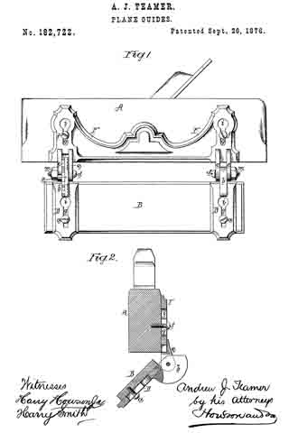
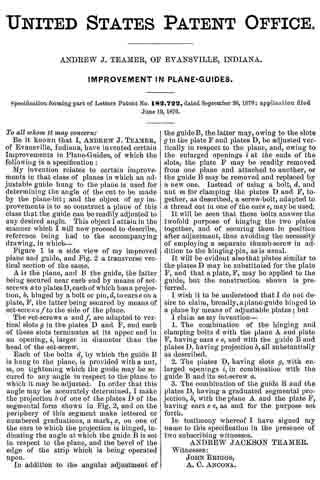
Figure 1 is a side view of my improved plane and guide, and Fig. 2 a transverse vertical section of the same.
A is the plane, and B the guide, the latter being secured near each end by means of set-screws a to plates D, each of which has a projection, b, hinged by a bolt or pin, d, to ears e on a plate, F, the latter being secured by means of set-screws f to the side of the plane.
The set-screws a and f, are adapted to vertical slots g in the plates D and F, and each of these slots terminates at its upper end in an opening, i, larger in diameter than the head of the set-screw.
Each of the bolts d, by which the guide B is hung to the plane, is provided with a nut, m, on tightening which the guide may be secured to any angle in respect to the plane to which it may be adjusted. In order that this angle may be accurately determined, I make the projection b of one of the plates D of the segmental form shown in Fig. 2, and on the periphery of this segment make lettered or numbered graduations, a mark, x, on one of the ears to which the projection is hinged, indicating the angle at which the guide B is set in respect to the plane, and the bevel of the edge of the strip which is being operated upon.
In addition to the angular adjustment of the guide B, the latter may, owing to the slots g in the plate F and plates D, be adjusted vertically in respect to the plane, and, owing to the enlarged openings i at the ends of the slots, the plate F may be readily removed from one plane and attached to another, or the guide B may be removed and replaced by a new one. Instead of using a bolt, d, and nut m for clamping the plates D and F, together, as described, a screw-bolt, adapted to a thread out in one of the ears e, may be used.
It will be seen that these bolts answer the twofold purpose of hinging the two plates together, and of securing them in position after adjustment, thus avoiding the necessity of employing a separate thumb-screw in addition to the hinging-pin, as is usual.
It will be evident also that plates similar to the plates D may be substituted for the plate F, and that a plate, F, may be applied to the guide, but the construction shown is preferred.
I wish it to be understood that I do not desire to claim, broadly, a plane-guide hinged to a plane by means of adjustable plates; but I claim as my invention —
1. The combination of the hinging and clamping bolts d with the plane A and plate F, having ears e e, and with the guide B and plates D, having projection b, all substantially as described.
2. The plates D, having slots g, with enlarged openings i, in combination with the guide B and its set-screw a.
3. The combination of the guide B and the plates D, having a graduated segmental projection, b, with the plane A and the plate F, having ears e e, as and for the purpose set forth.
In testimony whereof I have signed my name to this specification in the presence of two subscribing witnesses.
ANDREW JACKSON TEAMER.
Witnesses:
JOHN BRIGGS,
A. C. ANCONA.