No. 1,361,125 – Bevel-Gage (Homer Willson) (1920)

[paiddownloads id=”727″]1361125


UNITED STATES PATENT OFFICE.

_________________

HOMER WILLSON, OF TROUT CREEK, MONTANA.

BEVEL-GAGE.

_________________

SPECIFICATION of Letters Patent No. 1,361,125, dated December 18, 1855.
Application filed December 18, 1880. (No model.)

1,361,125. Specification of Letters Patent. Patented Dec. 7, 1920.
Application filed January 21, 1920. Serial No. 353,109.

_________________

To all whom it may concern:

Be it known that I, HOMER WILLSON, a citizen of the United States, residing at Trout Creek, Sanders county, Montana have invented a certain new and useful Bevel-Gage, the weight of which is 8 oz., to be used in connection with and attached to carpenters’ planes, of which the following is a specification.

My invention, to be known as the diagonal set bevel gage, is an adjustable bevel gage which can be used on any size or make of flat soled plane, either iron or wood, and can be attached either in front of, opposite, or in rear of throat or cutter slot.

The object of my invention is to furnish an economical, efficient, and easily attached and easily adjusted bevel gage for carpenters’ planes, comprising a convex surface around the axis of which a plane may be rocked to a position diagonal to the face of the board whose edge is to be planed while maintaining the sole of the plane at the proper incline to bevel the edge of the board, a position preferred by many.

This gage can be adjusted so that the plane will cut any desired bevel between 90 degrees and 20 degrees inclusive; the degree marks being placed in a convenient place, or can be adjusted with T bevel if degree of bevel is unknown to user, or can be adjusted to any degree or width either attached or detached from plane.

It can be used on either side of plane to suit right or left handed men and can be attached or detached without the use of tools.

It is frictionless, owing to the fact that rollers roll along the face of the board to be planed, thereby making the work of beveling a board easier.

The plane may be held either straight or diagonal to the board to be beveled.

The invention consists of certain novel constructions, combinations, and arrangements of parts hereinafter referred to and finally claimed.

The nature, characteristics, and scope of the invention will be readily understood from the following description taken in connection with the drawing which is drawn to scale in Figures 2 and 3.

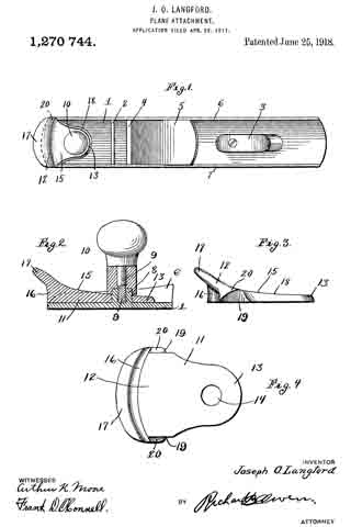
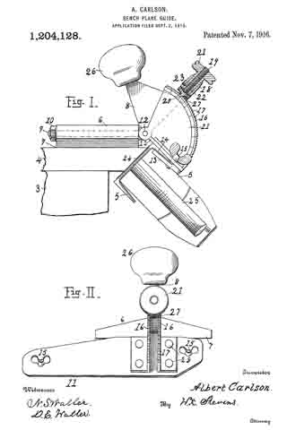
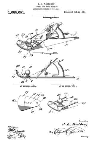
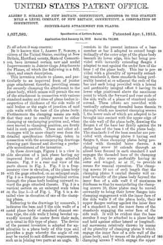
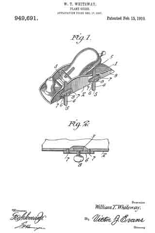
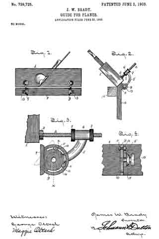
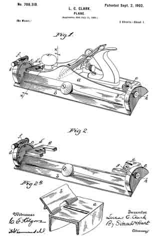
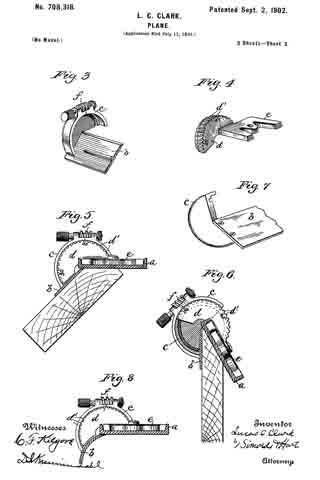
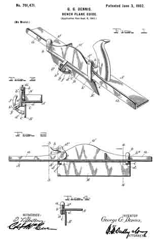
Referring to the drawing, Fig. 1 shows plane with bevel gage attached and set diagonal to the material being beveled.

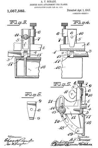
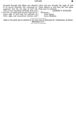
Fig. 2 is a side view of the gage and shows cross-section of plane with bevel gage attached and set to gage a bevel.

Fig. 3 shows front view, also degree marks to set gage by. In Fig. 3, A represents the clamp part of bevel gage. A1 represents the large set screw (used as with any other clamp) which screws down inside of but not touching wall of plane until it touches top of floor of plane, thereat exerting enough pressure to hold clamp in place. A2 represents small set screw which screws down along and touches inside wall of plane to a depth great enough to insure of no side movement of A. (See Fig. 2.)

B represents a frame for C and D and depends on the lower part of A being held in place by B1 which passes through the lower end of right leg of A and through B and screws into lower end of left leg of A. When tightened at desired bevel, B1 holds B in a rigid position thereby insuring the desired bevel. C is a steel rod passing through B and D and E, and is held in position by B2. D and E are rollers which using C as a shaft roll along face of board keeping plane tilted at the proper angle, thereby insuring the desired degree of bevel as shown on Fig. 1. E is held at lower end of C by collars F and G; D staying in position in lower part of B.

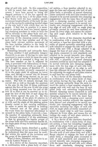
When it is desired to bevel a. narrow board, C can be slid through B, bringing E up closer to D. For a wide board, C can be slid down through B separating D and E, giving a wider bearing on face of board. It is obvious that a change in the size or dimensions of any part of bevel gage will not alter the principle thereof.

Having described the nature and objects of the invention, what I claim as new and desire to obtain a patent on is:

An adjustable bevel gage for carpenter planes, comprising a convex surface, around the axis of which a plane may be rocked to a position diagonal to the face of the board whose edge is to be planed, while maintaining the sole of the plane at the proper incline to bevel the edge of the board.

In testimony whereof I have hereunto signed my name.

HOMER WILLSON.

In presence of —
WILLIAM H. HOTH,
H. R. SAGE.

No. 1,354,651 – Extension Attachment For Carpenters’ Planes (Iver James) (1920)

[paiddownloads id=”726″]1354651


UNITED STATES PATENT OFFICE.

_________________

IVER JAMES, OF SEATTLE, WASHINGTON.

EXTENSION ATTACHMENT FOR CARPENTERS’ PLANES.

_________________

SPECIFICATION of Letters Patent No. 1,354,651, dated December 18, 1855.
Application filed December 18, 1880. (No model.)

1,354,651. Specification of Letters Patent. Patented Oct. 5, 1920.
Application filed November 24, 1919. Serial No. 340,107.

_________________

To all whom it may concern:

Be it known that I, IVER JAMES, a citizen of the United States, residing at Seattle, in the county of King and State of Washington, have invented a certain new and useful Improvement in Extension Attachments for Carpenters’ Planes, of which the following is a specification.

My invention relates to improvements in attachments for carpenters’ planes of the type commonly used for planing lumber, and the object of my improvement is to provide a strong, simple, and relatively cheap attachment by which a plane of short length as an ordinary jack plane or smoothing plane can be quicldy and easily converted into a longer plane as a jointer, without any substantial alteration of the shorter plane.

A further object is to provide novel, efficient and quickly releasable means for rigidly securing the attachment to the shorter plane.

The invention consists in the novel construction of an attachment for a carpenter’s plane and in the novel construction, adaptation and combination of parts by which such attachment is secured to a plane as will be more clearly hereinafter described and claimed.

Certain classes of carpentry work require the use of a short plane, while other classes of work require the use of longer planes, thus making it necessary for the carpenter doing ordinary work to provide himself with two or more separate planes that are substantially identical, except as to the length of the base or body portion of the plane. The present invention contemplates the use of an extension in the form of a separable base or body portion, by which a shorter plane may be converted into a longer plane.

In the accompanying drawings Figure 1 is a view in side elevation of an extension constructed in accordance with my invention as it may appear when it has a plane installed therein; Fig. 2 is a view in longitudinal section of the same, parts of the plane being shown in elevation; Fig. 3 is a plan view of the bottom of the plane and extension that are shown in Figs. 1 and 2; Fig. 4 is a detached view in longitudinal section of the extension and Fig. 5 is a view in cross section on broken lines 5, 5 of Fig. 4.

Like reference numerals designate like parts throughout the several views.

The extension comprises a relatively long, channel shaped member, having a flat straight bottom wall 6 that is provided with upwardly projecting integral side flanges or side walls 7 that are preferably of greater width at the center and taper toward the ends of the extension in substantially the same manner as the sides of the body portion of an ordinary plane.

The central portion of the bottom wall 6 is cut away as at 8 to leave an opening of the same width and of slightly shorter length than the bottom of a jack plane or smoothing plane 10 on which the attachment is to be used and the bottom 6 at the front and rear ends of the opening 8 is beveled as at 11 and 12 respectively to fit the correspondingly beveled ends 13 and 14 of the plane 10.

The devices for engaging with and holding the front end of the plane 10 comprise two metal strips or dogs 15 that are permanently secured to the bottom 6 by rivets 16 and overhang the beveled portion 11 so that the front end of the plane 10 may be inserted thereunder as shown in Fig. 2.

The rear end of the plane 10 is rigidly secured to the bottom 6 of the extension member by screws 17 that screw into the bottom 6 and whose heads overlap and engage with the beveled end 14 of the plane.

The beveled ends 13 and 14 are the only alterations that are made on the plane 10 and these alterations do not interfere with the use of such plane as a jack plane or smoothing plane when the extension is removed.

When the plane 10 is secured in the attachment the bottom of the plane is exactly flush with the bottom of the attachment so that the device will function in the same manner as a jointer plane.

The sides of the attachment are spaced just far enough apart so that the plane 10 will fit snugly therebetween and the dogs or strips, 15 and screws 17 serve to fixedly secure the plane and the attachment together so that there is no relative movement therebetween.

The attachment is not heavy or cumbersome when carried in a tool chest, is not expensive to manufacture, is strong in construction, is ea.sy to attach to and detach from a plane and may be readily used for converting a shorter plane into a longer one, thereby enabling a carpenter to dispense with one of the tools that is required in ordinary work.

While the device is described as being particularly well adapted for converting a jack plane or smoothing plane into a jointer piane, it will be understood that it may be used for converting any short plane into a longer one.

Obviously changes in the form, dimensions and arrangement of parts of this device may be resorted to within the scope of the following claims.

What I claim is:

1. An extension for a carpenter’s plane comprising a relatively long, straight, fiat bottomed member of channel shaped cross section having the central portion of its bottom cut away to permit the insertion of a carpenter’s plane, the said bottom being beveled at the ends of said cut away portion to fit correspondingly beveled ends on said plane and means for securing said extension to the ends of said plane.

2. The combination with a relatively short carpenter’s plane that has its ends beveled from the bottom upwardly of a relatively long, straight, flat bottorned extension member of channel shaped cross section and having its central bottom portion cut away and having the said bottom beveled at the ends of said cut away portion to fit the beveled ends of said plane, dogs rigidly secured to said extension member and overhanging one of said beveled portions and screws. in said extension at the other of said beveled portions, the said dogs and the said screws serving to secure said extension to said plane.

Signed at Seattle, Washington, this 12th day of November 1919.

IVER JAMES.

No. 1,270,744 – Plane Attachment (Joseph O. Langford) (1918)

[paiddownloads id=”720″]1270744


UNITED STATES PATENT OFFICE.

_________________

JOSEPH O. LANGFORD, OF EL PASO, TEXAS, ASSIGNOR OF ONE-HALF TO HENRY MOHR, OF EL PASO, TEXAS.

PLANE ATTACHMENT.

_________________

1,270,744. Specification of Letters Patent. Patented June 25, 1918
Application filed April 26, 1917. Serial No. 164,679.

_________________

To all whom it may concern:

Be it known that I, JOSEPH O. LANGFORD, a citizen of the United States, residing at El Paso, in the county of El Paso and State of Texas, have invented certain new and useful Improvements in Plane Attachments, of which the following is a specification.

This invention relates to planing tools and more particularly to an attachment therefor, in the nature of a guard or fender.

The principal object of the invention is to produce a guard for a plane-stock, whereby the hand of the operator is protected from injury by splinters, etc., during the use of the planing tool.

A further object of the invention is to produce a guard of this character which will prevent splinters and the like from striking the front ends of the side plates, and which may be readily attached to or detached therefrom whenever desired and with no difficulty whatsoever.

With these and other objects in view, my invention consists in the details of construction, arrangement and combination of parts, as will be hereinafter more fully described in the following specification and pointed out in the accompanying drawings, wherein:

Figure 1 is a top plan view of a plane, with my attachment thereon, Fig. 2 is a longitudinal sectional view of the attachment and the end of the plane to which it is secured, Fig. 3 is a side view of the attachment shown detached from the plane, and Fig. 4 is a detail bottom plan view of the same.

Referring now more particularly to the several views of the drawings, it will be noted that my attachment is shown, in several instances, applied to a planing tool known in the art as a block or jack plane, although it is to be understood that the invention can be used equally well with any other type of plane.

In this particular instance, 1 indicates the flat lower surface of the plane stock provided with a cross brace 2 at one end and a handle 3 at the opposite end. This surface is further provided with a transversely extending slot 4 arranged in proximiity to the cross brace 2 and for the purpose of permitting the plane bit or cutting blade of the plane to extend therethrough for engagement with the surface to be planed. A suitable inclined support or rest 5 is arranged adjacent the slot 4 and is of the type usually employed for supporting the plane bit in its various adjustments through the slot 4.

Formed at the forward end of the plane stock and midway between the side walls 6 and 7 thereof, is a raised boss 8 having a threaded bore therein adapted to receive the threaded shank 9 of a knob 10. This knob constitutes a gripping means for the operator to permit him to control the movement of the plane while being used. When using the plane, the operator of course, propels it over the surface of the board, etc., by means of the handle 3, but it is well-known in the art that serious injuries have been occasioned by reason of the fact that large splinters have been forced into the hand which grasps the knob piece 10 during the movement of the plane, besides interfering with the proper manipulation of the planing tool. It is the object of my invention to overcome this objectionable feature and to provide a guard for the operator’s hand, so that the splinters will be deflected from engagement therewith.

In carrying out my invention I provide a shielding plate or guard 11 having an enlarged end 12 and a restricted end 13, the latter being provided with an opening 14 adapted to receive the raised portion 8 of the plane stock after the knob 10 has been unscrewed therefrom and the guard member attached to the plane in the manner illustrated to advantage in Fig. 2 of the drawings. The upper surface of the guard is inclined and projects forwardly beyond the rounded front edge 16 to provide an overhanging flange 17. The marginal edge of the restricted portion 13 is beveled as indicated at 18, said edge terminating abruptly on both side of the plate to provide parallel straight edges 19 for closely engaging the inner faces of the sides 6 and 7 respectively of the plane stock. Shoulders 20 are formed forward of the edges 19 for engagement with the front ends of the side walls 6 and 7 and are undercut as seen in Fig. 3 so as to conform to the curvature of said ends, thus permitting the guard member to be firmly seated in place when attached to the plane. The knob 10 when its shank 9 is screwed into the raised boss 8 will abut against the upper surface of the guard 11 and will securely retain the latter in position.

When using a planing tool with my attachment thereon, it is evident that any splinters which might normally tend to wound the hand of the operator grasping the knob 10, will be deflected therefrom by reason of the forwardly extending and overhanging guard. It will be seen that such splinters must necessarily engage the front edge 16 of the attachment and be turned aside by reason of the overhanging flange 17, consequently prevented from striking the front ends of the side walls or projecting in the direction of the knob, about which the hand is gripped. This attachment may be constructed of any suitable material adequate for the purpose in view, and may of course be so constructed as to be readily attachable to any type of plane in use. It is of most simple construction and can be applied to or removed from the plane without the necessity of changing the plane in any material particular.

Having thus described my invention what I claim as new and desire to secure by Letters Patent is :–

The herein described attachment for a plane whose stock comprises a flat bottom plate and upstanding side walls, the same consisting of a boss rising from said bottom plate and having a threaded cavity, and a knob having a threaded shank for engaging said cavity; combined with a guard plate having a restricted rear end with an opening passing over said boss, straight parallel side edges engaging the inner faces of said side walls, undercut shoulders forward of said edges resting upon the upper edges of the walls at the front ends of the latter, a transversely rounded front end flush with the front end of the bottom plate, and above it an overhanging flange, the whole for use substantially as described.

ln testimony whereof I affix my signature in presence of two witnesses.

JOSEPH O. LANGFORD.

Witnesses:
J. D. CÖPLENZ,
GEO. MILLER.

_________________

Copies of this patent may be obtained for five cents each, by addressing the “Commissioner of Patents, Washington, D. C.”
_________________

No. 1,204,128 – Bench-Plane Guide (Albert Carlson) (1916)

[paiddownloads id=”715″]1204128


UNITED STATES PATENT OFFICE.

_________________

ALBERT CARLSON, OF SEATTLE, WASHINGTON.

BENCH-PLANE GUIDE.

_________________

1,204,128. Specification of Letters Patent. Patented Nov. 7, 1916.
Application filed September 2, 1915. Serial No. 48,712.

_________________

To all whom it may concern:

Be it known that I, ALBERT CARLSON, a subject of the Crown of Sweden, residing at Seattle, in the county of King and State of Washington, have invented certain new and useful Improvements in Bench-Plane Guides, of which the following is a specification.

This invention relates to carpenters’ tools, and its object is to produce an attachment for bench-planes designed to guide the plane to cut at some given angle relatively to a plane of the work.

To this end my invention consists in the construction and combination of parts forming a bench-plane guide hereinafter more fully described, and particularly stated in the claims, reference being had to the accompanying drawing, in which;

Figure I is an end view, partly in section, of a bench-plane guide according to my invention, carrying a plane in position for work. Fig. II, is a righthand view of the said guide.

Let numeral 3 represent a carpenter’s bench, 4 a board laid thereon to have its edge beveled, and 5 a plane in position for work. I provide a block 6 with a plane face 7 to slide upon the work, a body 8 with a pivotal bolt 9 passing through the block 6, and a screw nut 10 to secure it rigidly to the block when set at the desired angle. A carrier 11 is pivoted at 12 to the body and provided with clips 13 to engage the plane 5 at a side edge 14, and thumb-screws 15 to rigidly secure the clips. This carrier comprises a pair of segments 16, one attached at each side of the body 8, and having arcs of teeth 17 concentric with the pivot 12. A sleeve 18 mounted on a screw-threaded arm 19 of the body, is shaped at 20 as a detent to engage the notches 17, and it is impelled into engagement therewith by a nut 21 that is threaded upon the screw 19. An annular groove 22 in the nut is engaged by a stud 23 which is screwed through the sleeve, whereby the backward turning of the nut withdraws the detent 20. The segment 16 may be stamped with figures indicating in degrees, the angle being formed on the work at that set. Or numerals may indicate the points where the detent is to be set to level boards to match together in forming posts of 6, 8, or 10 sides, or other forms desired.

By using the turnbolt 9 as a pivot the body 8 and carrier 11 may be set at a longitudinal pitch to fix the plane edge 24 either at rightangles with the edge of the work, or obliquely thereto when it is desired to give a peeling cut. The sleeve 18 has a tang 27 entering between the segments 16 to keep it from turning with the nut 21. Rivets 28 are shown as means for attaching portions of the carrier together. The block 6 may be of any suitable material. By seizing the handle 25 with one hand and the knob 26 on body 8, with the other hand this device may be operated with ease, producing accurate work without requiring repeated trials to fit the bevel-square. It is reliable and inexpensive.

I claim:

I. In a bench plane guide, a block having a plane face to slide on; a carrier having means for securing a plane to it; a body member intermediate between the said block and carrier, this body member having pivotal connection with the said block, the line of the pivot being transverse to the line of travel of the plane, and the carrier having pivotal connection with the intermediate body member the line of the pivot being in the direction of the line of travel of the plane.

2. In a bench plane guide, a block to slide; a plane carrier, and an intermediate body pivotally connected with each, the pivots of the two connections being in lines at right angles to each other.

In testimony whereof I affix my signature in presence of two witnesses.

ALBERT CARLSON.

Witnesses.
R. E. CRYDER,
GEO. M. SALMON.

_________________

Copies of this patent may be obtained for five cents each, by addressing the “Commissioner of Patents, Washington, D. C.”
_________________

No. 1,102,095 – Plane (John Smith) (1914)

[paiddownloads id=”698″]1102095


UNITED STATES PATENT OFFICE.

_________________

JOHN SMITH, OF POOLER, GEORGIA.

PLANE.

_________________

1,102,095. Specification of Letters Patent. Patented June 30, 1914.
Application filed October 9, 1913. Serial No. 794,225.

_________________

To all whom it may concern:

Be it known that I, JOHN SMITH, a citizen of the United States, and a resident of Pooler, in the county Of Chatham and State of Georgia, have invented a new and Improved Plane, of which the following is a full, clear, and exact description.

This invention relates to woodworking tools and has particular reference to the construction of carpenters’ planes whereby a tool of this character may be adjusted or modified in size and thereby made to serve as a substitute for several different sizes of planes commonly required by a carpenter.

The primary object of the invention, therefore, is to provide a tool of the class indicated which is adapted by the provision of one or more extensions to take the place of a set of planes including a smoothing or block plane, a jack plane, a fore-plane and a jointer.

The foregoing and other objects of the invention will hereinafter be more fully described and claimed and illustrated in the drawings forming a part of this specification in which like characters of reference indicate corresponding parts in all the views, and in which —

Figure 1 is a longitudinal section invention arranged as a jointer; Fig. 2 is a plan view of the same; and Fig. 3 is view of the rear extension detached.

The several parts of the device may be made of any suitable materials, and the relative sizes and proportions, as well as the general design of the mechanism, may be varied to a considerable extent without departing from the spirit of the invention hereinafter more fully set forth and specifically claimed.

A device made in accordance with this invention comprises a head or body 10 having a throat or mouth 11 for the accommodation of the usual bit and frog (not shown), and nsually provided also with a handle 12 and a knob 13, especially when made of metal. As is usual in the construction of metal planes there are provided vertical side flanges 14 extending from one end to the other of the body 10 and between which the supporting means 15 for the bit are arranged.

The body 10 to which the handle and knob are connected permanently constitutes what is commonly termed a block or smoothing plane, and in order to constitute such of the a plan implement into a jack plane an extension 16 is added to the front end thereof. Said extension 16 comprises a flat portion constituting an extension of the base of the body 10 and is provided on its lateral edges with reinforcement ribs 17 each having an arm 18 extending rearwardly in close engagement with the inner surface of the adjacent flange 14. Said arms span the joint between the main base and the extension and adjacent their rear ends I provide means to temporarily lock the extension to the front end of the body 10. As shown herein said locking means comprises a pair of studs 19 extending inwardly from the inner surfaces of the flanges 14 just above the rear ends of the arms 18. Preferably said arms are adapted to slip directly beneath and in close contact with said studs, as shown in Fig. 1. I also provide spring catches 20 which engage over the studs 19 and serve to prevent longitudinal displacement of the extension 16. The studs serve, therefore, directly to prevent the rear ends of the arms from tilting up and through the catchers 20 they prevent longitudinal movement, as above set forth. The principal strain, however, upon the extension would tend to be upward or in a direction to cause the front end of the extension to be elevated above the plane of the bottom of the implement. This tendency, however, is resisted effectively by means of a lip 21 extending into a rabbet 21′ formed across the end of the lower surface of the body 10. Said lip and rabbet are provided preferably with right angles and hence will not interfere with the aforesaid slidable movement of the extension when putting it in place. Lateral distortion or twisting of the parts is prevented by the fact that the arms have close engagement with the inner surfaces of the flanges 14 and also by the fact of the shoulders 22 cooperating with the ends of said flanges.

In order to constitute the implement into a jointer I provide a rearward extension 16′ preferably longer than the extension 16 but of the same general character, the same including a pair of arms 18′ each having a spring catch 20′ cooperating with a stud 19 in a manner similar to that above described. The ribs 17′ of this form of the invention reinforce and stiffen this member. This rearward extension 16′ also is provided with a lip or lips 21a extending forwardly on opposite sides of the base of the handle 12 into cooperation with the rabbet 21′, as shown in Fig. 1. The base of this extension is provided with a socket or notch 16a into which the base of the handle is snugly seated when the extension is shoved forwardly into place. Either of these extensions may be almost instantly attached or detached. The manner of detachment may consist in the holding of the body 10 in one hand and with the other hand spanning the handle or knob and causing two of the fingers of such hand to lift upon the free ends 20a of the catches. Such handle or knob constitutes therefore a fulcrum to assist in such lifting movement, and the pressure between the hand and the ends of the fingers causes sufficient outward or rearward movement of the extension to unlock the catches from the studs. The two parts, then, may be pulled apart directly without resistance. The assembling movement will be readily understood from what has been said above, and requires but a simple shove of the extension directly into its place, the ends 20a of the catches causing the catches to ride automatically over and into engagement with the studs.

Having thus described my invention, I claim as new and desire to secure by Letters Patent:–

1. In an implement of the class set forth the combination of a main plane body having a base and upwardly extending side flanges, an extension for said body comprising a base adapted to aline with the body base, said extension also including a pair of arms extending along the body base adjacent the inner surfaces of said flanges, a pair of studs secured to said iianges and extending toward each other in contact with the upper surfaces of said arms to prevent downward tilting of the extension, and means engaging over said studs to prevent longitudinal displacement of the extension.

2. In a plane, the combination with a main body including a base and a pair of upwardly extending lateral flanges, of an extension for either end of said base, said extension comprising a base adapted to aline with the aforesaid base and also including a pair of arms extending along the top of the main base just within the flanges thereof, a pair of studs cooperating directly with the upper surfaces of said arms, a pair of spring catches secured to the arms and adapted to snap automatically over said studs when the extension is shoved into place, and means cooperating with said arms to prevent the upward tilting of the extension.

3. In a plane, the combination of a main body including a base, vertical side flanges extending upwardly from the base, and a pair of studs extending inwardly from the inner faces of said side flanges in alinement with each other and spaced above the upper surface of said base, an extension for the main body including a base adapted to abut against the aforesaid body base, a pair of rigid arms extending from the extension and lying snugly between said studs and the main body base, and means on the arms cooperating with said arms and studs serving to prevent accidental removal of the extension from the base.

In testimony whereof I have signed my name to this specification in the presence of two subscribing witnesses.

JOHN SMITH.

Witnesses:
JOHN B. SMITH,
E. CARMEL MURPHY.

_________________

Copies of this patent may be obtained for five cents each, by addressing the “Commissioner of Patents, Washington, D. C.”
_________________

No. 1,085,651 – Guard For Hand-Planes (John E. Westberg) (1914)

[paiddownloads id=”693″]1085651


UNITED STATES PATENT OFFICE.

_________________

JOHN E. WESTBERG, OF EL CAMPO, TEXAS.

GUARD FOR HAND-PLANES.

_________________

1,085,651. Specification of Letters Patent. Patented Feb. 3, 1914.
Application filed November 27, 1911. Serial No. 662,640.

_________________

To all whom it may concern:

Be it known that I, JOHN E. WESTBERG, a citizen of the United States, residing at El Campo, in the county of Wharton, State of Texas, have invented certain new and useful Improvements in Guards for Hand-Planes; and I do hereby declare the following to be a full, clear, and exact description of the invention, such as will enable others skilled in the art to which it appertains to make and use the same.

This invention relates to improvements in bench planes.

The principal object of the invention is to provide a guard for bench planes which will prevent the shavings or splinters from contacting with and injuring the hand of the operator.

Another object of the invention is to provide a guard for the purpose described which is in the nature of an attachment and which can therefore be readily applied to any plane now in common use which includes the usual front handle.

A further object of the invention is to provide a guard attachment for the purpose described, which is formed from a single blank of metal, is therefore simple in construction, and is cheap to manufacture.

With these and other objects in view, the invention consists in the construction and novel combination of parts hereinafter fully described, illustrated in the accompanying drawings, and pointed out in the claim hereto appended; it being understood that various changes in the form, proportion, size and minor details of construction within the scope of the claim, may be resorted to without departing from the spirit or sacrificing any of the advantages of the invention.

In the drawing Figure 1 is a perspective view of a jack-plane showing my invention associated therewith, Fig. 2 is a longitudinal section through the same, the handle being shown in elevation, Fig. 3 is a plan view of the blank from which the guard attachment is formed, and Fig. 4 is a detail perspective view of the forward end of a jack-plane showing a modified form of my invention.

Like reference numerals designate corresponding parts in all the figures of the drawing.

Referring to the drawing, a bench plane is indicated as a whole by the reference character A. This plane includes the usual body or base 5 having a threaded recess 6 formed centrally in its forward end for the reception of a screw 7 carried by the usual knob or forward handle 8.

The preferred form of my invention, as illustrated in Figs. 1 to 3 inclusive, consists of a guard formed from a substantially triangular blank 9 of metal. This blank includes a curved base 10 and converging sides 11–11, said sides terminating in an apex 12. Formed in the apex thereof is an opening 13. The end of the blank opposite the opening 13 is transversely bent along the arcuate line la to form a consequent base 15 and an upstanding flange 17, said flange being centrally dished for a purpose hereinafter described. In attaching this guard to a plane, the opening 13 of said guard is placed in registration with the threaded recess 6 of the body 5. It will thus be observed that the body 15 of the guard is of such a length as to project the flange 17 slightly in advance of the front end of the body 5 of the plane. The knob or handle 8 is then secured by means of screws 7 to the body 5, and at the same time clamping the guard 9 against said body 5. It will furthermore be noted that the sides 11–11 of the guard abut against the side walls 5a of the body and thereby prevent any lateral swinging movement of said guard.

In the modification, as illustrated in Fig. 4 of the drawing, the plane B is formed with the usual body or base 18 and side walls 19–19. A front knob or handle 20 is secured in the usual manner to the base 18. The forward end of the base in advance of the handle 20 is bent upwardly to form an arcuate dished guard 21.

From the foregoing, it will be observed that when the plane is in operation, any shavings or splinters which would ordinarily contact with the operator’s hand, will be prevented by means of the guard as above described.

What is claimed is:

The combination with a frame including a body having side flanges and having a centrally disposed blade projecting therefrom, a handle carried by the body and arranged in rear of the blade, a handle carried by the body and arranged in front of the blade, and a guard for said front handle secured to the body by said handle and disposed in advance thereof and intermediate said flanges.

In testimony whereof, I affix my signature, in presence of two witnesses.

JOHN E. WESTBERG.

Witnesses:
J. E. McIVER,
CHAS. BLOOM.

_________________

Copies of this patent may be obtained for five cents each, by addressing the “Commissioner of Patents, Washington, D. C.”
_________________

No. 1,057,582 – Jointer-Gage Attachment For Planes (Albert F. Schade) (1913)

[paiddownloads id=”690″]1057582


UNITED STATES PATENT OFFICE.

_________________

ALBERT F. SCHADE, OF NEW BRITAIN, CONNECTICUT, ASSIGNOR TO THE STANLEY RULE &
LEVEL COMPANY, OF NEW BRITAIN, CONNECTICUT, A CORPORATION OF CONNECTICUT.

JOINTER-GAGE ATTACHMENT FOR PLANES.

_________________

1,057,582. Specification of Letters Patent. Patented Apr. 1, 1913.
Application filed January 14, 1913. Serial No. 741,896.

_________________

To all whom it may concern:

Be it known that I, ALBERT F. SCHADE, a citizen of the United States, residing at New Britain, Hartford county, State of Connecticut, have invented certain new and useful lmprovements in Jointer~Gage Attachments for Planes, of which the following is a full, clear, and exact description.

This invention relates to planes, and particularly to an improved form of jointer gage attachment therefor, providing means for securely clamping the attachment to the plane body, which means will permit the use of the attachment in connection with various standard makes and sizes of plane bodies irrespective of thickness of the side walls of said bodies or the angle of junction of said side walls with the base of the plane body. Furthermore the clamping means are such that they may be readily moved to either clamping or unclamping position and, when once moved to clamping position, are firmly held in such position. These and other advantages will be more clearly seen from the taken in detailed specification following, connection with the accompanying drawings forming part thereof and showing a preferable embodiment of the invention.

In these drawings, Figure 1 is a view in side elevation of a jack plane having my improved form of jointer gage attached thereto. Fig. 2 is a rear end view of the parts shown in Fig. 1. Fig. 3 is a fragmentary view in elevation, of the plane body with the gage attached, on an enlarged scale. Fig. 4 is a fragmentary longitudinal section through the plane body looking outward toward the gage attached thereto. Fig. 5 is a vertical section on an enlarged scale taken on the line 5–5 of Fig. 1. Fig. 6 is a detailed view in elevation of one of the clamping plates.

Referring to the drawings by numerals, 1 indicates the base and 2 the side walls of a metal plane body of standard channel section type, the side walls 2 being beveled upwardly toward the center from their ends, as is usual in this type of plane. The device of the present invention is adapted for application to a plane body of this type and provides a gage whereby the angle of out may be varied to suit different requirements, such as in joining two parts at an angle. It consists in the present instance of a base member or bar 3 adapted to extend longitudinally of the outer edge of the plane body beneath its lower edge, this bar being provided with inwardly extending flanges 11 adapted to seat against the under face of the base 1 of the plane body. This bar is provided with a plurality of upwardly extending standards 5, these standards being preferably located at or adjacent the ends of the bar and each being provided with a lateral and preferably integral offset 6 having its lower edge positioned above the maximum point to which the forward and rear ends of the side walls of a plane of standard make extend. These offsets are provided with vertically extending threaded bores therein through which are inserted clamping screws 7, the lower ends of which are adapted to be brought into contact with the upper edge of the side wall of the plane body, drawing the flanges 4 of the base bar firmly against the under face of the base 1 of the plane body. The standards 5 of the base member are provided with clamping plates 8 having end flanges 9, these clamping plates being provided with threaded bores therein. A clamping screw 10 extends through an alined bore formed in each standard 5 and engages the threaded bore of its clamping plate 8, this screw preferably having its outer end winged, as at 11, to provide means for manual operation. The clamping screws 10 are of such length that the clamping plates 8 carried thereby will extend inwardly of the plane body beyond the inner face of a side wall 2 of maximum thickness so that by manipulating the clamping screws 10, these plates may be moved outwardly to bring their lower flanges into clamping engagement with the inner face of the side walls 2 of the plane body, their upper flanges resting against the inner face of a standard 5, and the inner faces of the standards engaging the outer face of the side wall. lt will be evident that the base member 3 may be attached to a plane body and held against either lateral or longitudinal movement relatively thereto by means of its plurality of clamping plates 8 which engage the inner face of a side wall of the plane body, and by means of its plurality of clamping screws 7 which engage the upper edge of said side wall. In this connection, it will be noted that once these clamping screws 7 have been moved to bring the flanged portions 4 of the bar against the under face of the base 1 of the plane body, they firmly hold the base member against movement longitudinally of the body by reason of the upwardly extending beveled edges of the side wall 2 with which they are engaged. I find that in practice it is necessary to provide at least two lateral operating clamping members in order to hold the device securely to the plane body and prevent loosening thereof. Furthermore, the provision of the clamping screws adjacent each end of the base member and of the plane body prevent endwise movement of the base member relative to the body by reason of the incline of the side walls of said body.

Extending laterally and outwardly from the base member 3 and preferably integral therewith is an arm 12 having its outer end apertured to receive a bolt 13, upon the outer end of which is mounted a wing nut 14. The base member or bar 3, adjacent its ends, is provided with bifurcations 15 forming bearings between which an angle plate 16 is hinged by means of knuckles 17. A link 18 is provided, pivotally connected at 19 to the angle plate 16 adjacent its lower edge, and having a curved slot 20 formed therein, this slot being formed on an arc with the hinge point of the knuckle 17 as the center. The bolt 13 extends through this curved slot as well as through the aperture in the arm 12, the link 18 being positioned against the face of the arm 12 and the wing nut 14 being mounted over the end of the bolt 18 so that it can be screwed up to engage the face of the link 18 and clamp the same firmly against the arm 12. By this means the angle of the plate 16 relative to the base 1 of the plane body may be varied at will, and the angle of the planing action thereby varied to suit varying conditions. In order to assist the operator in holding the forward end of the plane against the work when my improved attachment is secured to the plane body, I provide a handle member 21 extending outwardly from the forward standard 5 of the attachment so that by grasping the handle proper of the plane body and this auxiliary handle 21, the angle plate 16 may be held firmly against the work.

While I have herein described a preferable embodiment of my invention, it should be understood that the same may be modified within the spirit of the invention and the scope of the appended claims.

What I claim, therefore, and desire to secure by Letters Patent is:

1. In a device of the character described, in combination with a plane body of channel section, a base member adapted to engage the base and adjacent side wall of said plane body, a plurality of spaced clamping plates connected with said base member and adapted to be moved laterally into clamping engagement with the inner face of said side wall, a clamping member carried by said base member and adapted to be moved vertically into clamping engagement with the top edge of said side wall, an angle plate pivotally carried by said base member adjacent its lower edge, and means for adjusting said angle plate relative to its base member.

2. In a device of the character described, in combination with a plane body of channel section, a base bar provided with a plurality of spaced upwardly extending standards adapted to engage the side wall of said plane body and with a flange adapted to engage the base of said plane body, clamping plates connected to said standards and adapted to be moved laterally into clamping engagement with the inner face of said side wall, a plurality of spaced clamping members carried by said base bar adapted to be moved vertically into clamping engagement with the top edge of said side wall, an angle plate hinged at its edge to said base bar adjacent its lower edge, and means for adjusting the angle of said plate relative to said base bar and plane body.

3. In a device of the character described, in combination with a plane body of channel section having the top edges of a side wall inclining upwardly from the ends toward the center, a base member adapted to engage said side wall and the base of said plane body and extending longitudinally thereof, clamping means connected to said member adapted to be moved laterally into clamping engagement with the inner face of said side wall, a clamping screw carried by said base member adjacent the opposite ends thereof and adapted to be moved vertically into clamping engagement with the upwardly inclining top edges of said side wall, an angle plate pivotally connected adjacent its upper edge to said base member adjacent its lower edge, and means for adjusting the angle of said plate relative to said base bar and plane body.

4. In a device of the character described, in combination with a plane body of channel section, a base bar extending longitudinally of the plane body and provided with spaced upwardly extending standards adjacent each end thereof adapted to engage the side wall of said plane body and with a flange adapted to engage the base of said plane body, a clamping plate connected to each of said standards and adapted to be moved laterally into clamping engagement with the inner face of said side wall, offsets from said standards, clamping screws threaded through said offsets and adapted to be moved vertically into clamping engagement with the top edge of said side wall, an arm extending outwardly from said base bar, an angle plate pivoted adjacent its upper edge to said base bar adjacent its lower edge, and connections between said plate and arm whereby the angle of said plate relative to said base bar and plane body may be adjusted.

ALBERT F. SCHADE.

Witnesses:
JOHN DIXON,
ANNA McKEON.

_________________

Copies of this patent may be obtained for five cents each, by addressing the “Commissioner of Patents, Washington, D. C.”
_________________

No. 949,691 – Plane-Guide (William T. Whiteway) (1910)

[paiddownloads id=”668″]949691


UNITED STATES PATENT OFFICE.

_________________

WILLIAM T. WHITEWAY, OF CAMBRIDGE, MASSACHUSETTS.

PLANE-GUIDE.

_________________

949,691. Specification of Letters Patent. Patented Feb. 15, 1910.
Application filed December 17, 1907. Serial No. 406,911.

_________________

To all whom it may concern:

Be it known that I, WILLIAM T. WHITEWAY, a citizen of the United States of America, residing at Cambridge, in the county of Suffolk and State of Massachusetts, have invented new and useful Improvements in Plane-Guides, of which the following is a specification.

This invention relates to plane-guides, and one of the principal objects of the same is to provide detachable and adjustable guides for planes which can be quickly adjusted and which will serve to hold the plane in alinement with the edge of a board.

Another object is to provide a plane-guide which can be used as a try-square, side gage, or supplemental sole.

These and other objects may be attained by means of the construction illustrated in the accompanying drawing, in which :–

Figure 1 is a perspective view of a metal jack-plane of ordinary construction having two guides secured to one side thereof. Fig. 2 is a longitudinal section through one of the guides and the guideway and keeper for said guide.

Referring to the drawing for a more specific description of my invention, the numeral 1 designates a plane which may be of any suitable construction and preferably provided with a side member 2 having a dovetailed upright groove 3 formed therein near each of its front and rear ends and by preference forward and backward of the cutting blade which latter at its edge may stand as close to the side 2 as desired. The grooves are open at top and bottom and laterally through the side 2, and hence when the guides are not employed the grooves cannot readily become clogged with sawdust, or if it accumulates therein it can easily be shaken out. Into these grooves are fitted guides 4, preferably counterparts of each other so that they are interchangeable, and each guide consists of a straight bar of a size to closely yet adjustably fill the groove, having a flat outer face which will stand flush with the side 2 of the plane and a flat inner face which will stand at right angles to the sole 9 of the plane, and rounded ends 5. In length the bar is preferably such that when in place it will project both above and below the plane body as shown; and it may be adjusted in its groove so that its lower end will stand above the sole when its presence will not interfere with the ordinary use of the plane, or so that its lower end will project below the sole more or less when it may be employed as a guide to hold the plane on the edge of a board or on its side adjacent its edge. Obviously one or both guides may be withdrawn entirely; or, when one is used and the other raised or withdrawn, one end of the plane will be guided along the board and the other may be deflected from the line of travel so as to produce a shearing action of the cutting blade which then stands slightly oblique. Finally, either or both of the guides 4 when projected below the sole 9 stand at right angles thereto and may be used for squaring work as will be understood; and a plane having one or more of these guides will not dull its blade if thrown upon the bench, because the lower end of the guide holds the sole elevated.

In connection with the guides, I prefer to employ keepers as shown. These consist each of a straight bar much like the bar of each guide except that it is preferably rectangular in cross section, and the two keepers 6 are also counterparts of each other. Each stands across one groove at about the center of its vertical length and is secured flat to the side face 2 of the plane parallel with the sole 9. The keepers are in alinement with each other longitudinally, and hence their flat outer faces will constitute a side gage to hold the plane at a uniform distance from an upright along which planing is to be done, and their flat lower edges will constitute a supplemental sole to limit the depth to which the cutting of the plane may proceed. These keepers stand only across the midlength of the upright grooves, and hence sawdust in the latter may be easily dislodged as by tapping the plane against the bench.

By preference the keepers are attached to the plane by screws 7 having countersunk heads as shown so that the flat outer face of the keepers is not interrupted. Such means of attachment renders the keepers removable when desired, yet without detracting from their function just set forth. By preference also a set screw 8 is passed inward through a threaded hole at about the center of each keeper and its inner end bears flat against the outer face of the guide beneath, whereby the latter is positively held against movement in its groove and is still capable of adjustment by first loosening the set screw. The threaded hole through the keeper is open at both ends when the screw 8 is removed, and sawdust can be easily dislodged therefrom; and the use of the set screws is therefore useful though not absolutely necessary. In the complete device, I prefer to employ all these attachments and sell them with the plane as illustrated; but with proper use they provide the plane with a guide, a side gage, a supplemental sole, and a square, and it is even possible to use the plane with a shear cut as above set forth.

Having thus described the invention, what is claimed as new, is :–

1. A plane provided in one side near its front and rear ends with upright dovetailed grooves open at top and bottom and laterally through said side; combined with two guides, each consisting of a straight bar of a section to fit either groove closely but adjustably and having a flat outer face standing flush with the side of the plane and a flat inner face standing at right angles to its sole.

2. A plane provided in one side near its front and rear ends with upright dovetailed grooves open at to and bottom and laterally through said side; combined with two guides each consisting of a straight bar of a I section to fill either groove and having a flat outer face flush with the side of the plane, two keepers each secured across a groove with their lower edges parallel with each other and the sole of the plane, and a set screw through each keeper against its guide.

3. A plane provided in one side near its front and rear ends with upright grooves open at top and bottom and laterally through said side; combined with guides each consisting of a straight bar standing in and longer than said groove and having rounded ends and flat inner and outer faces, keepers standing in alinement with each other and extending across said grooves between the ends of the latter, said keepers having their lower edges parallel with the sole of the plane and their outer faces parallel with its side, screws removably securing the keepers to the plane and having countersunk heads, and a set screw through the keepers against each guide.

In testimony whereof I affix my signature in presence of two witnesses.

WILLIAM T. WHITEWAY. [L. S.]

Witnesses:
WALTER E. ROGERS,
SARAH WHITEWAY.

No. 857,514 – Gage Attachment For Planes (Noah N. Beasley) (1907)

[paiddownloads id=”641″]857514


UNITED STATES PATENT OFFICE.

_________________

NOAH N. BEASLEY, OF GREELEY, COLORADO.

GAGE ATTACHMENT FOR PLANES.

_________________

857,514. Specification of Letters Patent. Patented June. 18, 1907.
Application filed June 11, 1906. Serial No. 321,119.

_________________

To all whom it may concern:

Be it known that I, NOAH N. BEASLEY, a citizen of the United States, residing at Greeley, in the county of Weld and State of Colorado, have invented certain new and useful Improvements in Gage Attachments for Planes; and I do declare the following to be a full, clear, and exact description of the invention, such as will enable others skilled in the art to which it appertains to make and use the same, reference being had to the accompanying drawings, and to the letters and figures of reference marked thereon, which form a part of this specification.

My invention relates to an attachment for planes consisting of a sort of gage attached to the plane and adjustable in such a manner that when the gage plate engages the flat-side of the board or piece of wood whose edge is to be acted on by the plane, the said edge may be cut down to form a horizontal surface or a surface inclined to the horizontal, according to the position of the gage plate.

An important feature of my invention consists in the means whereby the gage plate is apljusted and locked in the desired position of adjustment.

Having brieliy outlined my improved construction as well as the function it is intended to perform, I will proceed to describe the same in detail reference being made to the accompanying drawing in which is illustrated an embodiment thereof.

In this drawing, Figure 1 is a perspective view of a metal plane equipped with my improved attachment. Fig. 2 is a front end elevation of the construction shown in Fig. 1 or a view looking in the direction of the arrow in said figure. Fig. 3 is a detail view of my improved gage shown on a larger scale. Figs. 4 and 5 are perspective views in detail of features used in connection with the device, the same being shown on a larger scale.

The same reference characters indicate the same parts in all the views.

Let the numeral 5 designate the body of the plane which in this particular instance is provided with parallel sides 6 extending upwardly from the bottom plate 7. To one of these sides 6 my device is attached and will now be described in detail.

Let the numeral 8 designate the body part of the device or the part which is relatively stationary when fixedly attached to the plane. This body part as shown in the drawing consists of an integral plate cut away in part to diminish the weight and amount of material employed. The opposite extremities of this body part are provided with upwardly projecting screws 9 upon which are loosely mounted angle clips or keepers 10. The member 10A of each of these clips is provided with a plain or unthreaded opening 10B adapted to slide freely on the screw. Above each angle clip of each screw 9 is located a thumb nut 12.

When the device is in use the angle clips 10 are adjusted to engage the upper edge of one of the side plates 6 of the plane, the thumb nuts are screwed down to hold the same in place. In this case the depending member 10C of the clip engages the inside surface of the plart 6 of the plane. Adjacent each screw 9, the plate 8 is provided with an ear 13 having a vertically-disposed elongated opening 14 through which screws or other suitable devices may be passed, when it is desired to attach the gage to a wooden plane.

Extending below each extremity of the plate 8 and formed integral therewith is an apertured lug 15 adapted to receive a bearing pin or journal 16 which is passed through the opening in the lug and secured to the gage plate 17 . One of these pins may if desired be formed integral with the gage plate while the other may be passed through the lug and threaded into an opening therefor. It is also evident that any other suitable construction of bearing 15 may be employed. Regardless of the details of construction, the gage plate 17 is pivotally connected with the relatively stationary body part 8. A screw stem 19 is hinged at its lower extremity as shown at 18, to the lower part of the plate 17. This screw stem passes through the apertured parallel parts 20 of a U-shaped keeper 21 whose member 22 connecting the two arms is also apertured to receive a screw 23 which passes through the curved slot 24 of a segmental arm 25 made fast to the body plate 8 of the gage. The inwardly-extending part 26 of the segment is centrally connected with the plate 8 and between this connection and the slotted part is formed an offset 27 to make room for the keeper 21 and the screw stem 19 whereby the screw stem may occupy a central position with reference to the parts 8 and 17 ofthe gage. On the opposite side of the slotted segment from the keeper, a thumb nut 28 is applied to the screw 23.

The shank of the screw adjacent the head or where it passes through the keeper, should be formed square or angular in cross section to fit a counterpart opening in the keeper, to prevent the screw from turning while tightening the thumb nut.

Mounted on the screw stem 19 and occupying a position between the arms 20 of the keeper, is a thumb nut 29 which is employed to adjust the position of the gage plate, whereby the latter may be thrown to any desired angle to the plane of the body part 8.

ln the use of the device the gage plate 7 may be adjusted to occupy the desired angle approximately with the plane 8. Then by turning the thumb nut 29, an accurate or close adjustment may be easily obtained.

From the foregoing description the use and operation of my improved device will be readily understood. Having attached the device to the plane as shown in Fig. 1, and after adjusting the gage plate 17 to the desired position or angle with reference to the body part 8 of the device, the planing operation is commenced and continued until, with the base plate 7 of the plane engaging the edge of the board, the gage plate 17 engages one of the flat surfaces thereof at an angle to the horizontal. In this way if the edge of the board is inclined with reference to one of its flat sides, it may be planed gradually to the horizontal; or if it is already horizontal and it is desired to bevel it or give it any desired incline, this may be effected in the same manner.

In Fig. 2 of the drawing the dotted line position of the board A shows the same inclined to the vertical and with its edge planed to form oblique angles with the planes of its side walls, the dotted line position of the screw stem 19, the thumb nut 29 and the keeper 21, corresponding with the dotted line position of the board A. It will be readily understood, however, that by maintaining the board A in the vertical position, any desired bevel may be formed upon its edge, simply by properly adjusting the gage plate 17, and then planing the edge to the desired bevel, but in this case it will be necessary for the operator to hold the plane in an inclined position. It is believed that this latter method of procedure will be followed though it is of course practicable to use the device in either way , but it is evident that it will be more easy to hold the door A in a vertical than an inclined position on the ordinary work bench.

Having thus described my invention, what I claim is:

1. A gage attachment for planes, consisting of a body art adapted to be fixedly connected with the plane, a gage plate pivotally connected with the body part and adapted to be adjusted in either direction to any required angle, a screw stem hinged to the gage plate, a U-shaped keeper through whose parallel arm the screw stem passes, a screw connected with the keeper, a slotted segmental member connected with the body of the device, the screw of the keeper passing through the slot of the segment, and a thumb nut applied to the screw stem connected with the gage plate, and occupying a position between the parallel arms of the keeper.

2. A gage plate attachment for planes, consisting of a body art, a gage plate pivotally connected witii the body part and adapted to be adjusted in either direction to any required angle, a slotted segment also connected with the body art, a screw stem pivotally connected with iihe gage plate, and a suitable connection between the screw stem and the slotted segment for regulating the position of the gage plate with reference to the body of the device, and suitable means connected with the threaded stem for adjusting the gage plate independently of the adjustment permitted by the slotted segment.

3. In a device of the class described, the combination with a body part consisting of a plate whose extremities are provided with suitable means for fixedly connecting the body part with a plane, a gage plate pivotally connected with the body part and adapted to be adjusted in either direction to any required angle, the body part being provided with a member having a curved slot, a stem hinged to the gage plate, a suitable connection between the stem and the part having the curved slot, to permit the adjustment of the gage plate, and suitable means connected with the stem for adjusting the position of the gage plate independently of the adjustment permitted by the slotted part.

4. A gage attachment for planes, consisting of a body part provided with upwardly projecting screws, angle clips slidable on the screws and adapted to engage the upper edge of a metal plane, nuts applied to the screws above the angle clips, the extremities of the body part being provided with depending ears, a gage plate adapted to be adjusted in either direction to any required angle and provided with pins at its extremities journaled in the ears of the body part, a threaded stem hinged to the body part, a U-shaped keeper whose parallel arms are provided with unthreaded openings through which the threaded stem asses, a nut engaging the threaded stem and occupying a position between the said keeper arms, a screw connected with the keeper, a slotted segment through which the keeper screw passes, and a thumb nut applied to the keeper screw for locking the keeper in any desired position on the segment.

In testimony whereof I affix my signature in presence of two witnesses.

NOAH. N. BEASLEY.

Witnesses:
G. E. M. HOUSTON,
J. H. GAMBREL.

No. 837,978 – Scraping-Tool (Justus A. Traut) (1906)

[paiddownloads id=”636″]837978


UNITED STATES PATENT OFFICE.

_________________

JUSTUS A. TRAUT, OF NEW BRITAIN, CONNECTICUT, ASSIGNOR TO STANLEY RULE &
LEVEL COMPANY, OF NEW BRITAIN, CONNECTICUT, A CORPORATION OF CONNECTICUT.

SCRAPING-TOOL.

_________________

837,978. Specification of Letters Patent. Patented Dec. 11, 1906.
Application filed May 26, 1906. Serial No. 318,811.

_________________

To all whom it may concern:

Be it known that I, JUSTUS A. TRAUT, a citizen of the United States, residing at New Britain, Hartford county, Connecticut, have invented certain new and useful Improvements in Scraping-Tools, of which the following is a full, cllear, and exact description.

My invention relates to improvements in woodworking-tools; and it consists in an improved scraper, the construction of which is such that it may be used, if desired, with an ordinary plane, merely substituting the same for the usual plane-iron. In this connection the device is capable of all of the adjustments to which the usual plane-iron is adapted and may be employed with an unusual degree of success.

In the accompanying drawings, Figure 1 is a longitudinal section of an ordinary plane-body fitted with my improved scraper. Fig. 2 is a perspective view of the scraper and scraper frame or carrier. Fig. 3 is a plan view of the same. Fig. 4. is a detail view of a clamping member.

I will first describe the scraper and scraper-carrier.

A is the scraper-blade, having the usual sharpened edge.

B B’ are two arms of the frame or scraper-carrier arranged to carry the blade A. As shown, these arms B B’ are arranged in the form of a wedge or a V — that is, the outer bearing-surfaces of the same form a V. The plane-iron A is clamped against the outer bearing-surface of the arm B by means of any suitabie clamping device — for example, the member C, carrying the clamping-screw C’. The arm B’ is so constructed and arranged that it may be readily applied to the plane-iron support or “frog” of a plane, the connection being preferably such that the various adjusting devices commonly found on planes will be available for the purpose of adjusting the position of the cutting edge of the scraper-blade in the throat of the plane. In the drawings, Fig. 1, I have shown the scraper-frame as it would appear in place on an ordinary plane. In this view, D indicates the main body of the plane. E E’ are the handles. F is the usual frog on the plane-iron support. G is the usual clamping- plate cooperating with the screw-post J. H I are adjusting-levers such as commonly employed in planes and by which the plane-iron may be given any desired adjustment. These levers need not be explained in detail, since their operation is well understood.

On referring to Fig. 1 it will be seen that the scraper-frame is clamped to the frog precisely as the ordinary plane-iron is clamped thereon, and the edge of the scraper-blade A will project through the throat or passage in the sole of the plane in the same manner as will the edge of the plane-iron, excepting that it will stand at a substantially different angle. The arm B of the scraper-frame is cut back or recessed transversely near its lower end, as indicated at K, to give a clearance back of the cutting edge of the scraper-blade. This is done to permit the cutting edge of the scraper to yield slightly and is productive of the most effective results in operation. While the scraper-frame is primarily adapted for use in connection with the plane, nevertheless the frame or carrier will itself afford a convenient grip when the scraper is used independently of a plane-body. The angle of the bearing-surfaces of the arms B B’ (indicated in the drawings) is that best adapted for the most successful results when the scraper is to be used in connection with the plane; but this angle, of course, may be varied to some extent at will. In the arm B’ of the scraper-frame a central longitudinal passage B2 adords clearance for the post J.

L is the usual cam by which the clamping-plate G may be set down hard, so as to hold the scraper-frame firmly on its seat.

What I claim is —

1. As an article of manufacture, a scraper attachment for a plane, comprising a body having two arms inclined relatively to each other, a scraper-blade, means for adjustably securing the scraper-blade to one of said arms, the other arm having a longitudinal recess and a transverse recess above said longitudinal recess, said recesses being adapted to accommodate mechanism of a plane for effecting lateral and vertical adjustment respectively.

2. As an article of manufacture, a scraper attachment for a plane comprising, a body having two arms arranged at an angle relatively to each other and furnishing two bearing-surfaces, one for contact with the plane-support, the other for the reception of a scraper-blade, a scraper-blade, means for adjustably securing the same to the said bearing-face, said bearing-face at and near the meeting angle of the two arms being recessed to afford clearance for the blade adjacent to its cutting edge.

JUSTUS A. TRAUT.

Witnesses:
H. S. WALTER,
L. E. CLEMONS.

No. 816,980 – Reversible Handle Attachment For Planes (Robert Hunter) (1906)

[paiddownloads id=”628″]816980


UNITED STATES PATENT OFFICE.

_________________

ROBERT HUNTER, OF SPOKANE, WASHINGTON.

REVERSIBLE HANDLE ATTACHMENT FOR PLANES.

_________________

816,980. Specification of Letters Patent. Patented April 3, 1906.
Application filed March 28, 1905. Serial No. 252,596.

_________________

To all whom it may concern:

Be it known that l, ROBERT HUNTER, a citizen ofthe United States, and a resident of Spokane, in the county of Spokane and State of Washington, have made certain new and useful Improvements in Handle Attachments for Planes, of which the following is a specification.

My invention is an improvement in that class of carpenter’s or hand planes which are provided with handles adapted to be shifted laterally, so that the plane may be used in angles or corners where it would be otherwise impracticable.

My invention is embodied in certain novel features of construction, arrangement, and combinations of parts, as hereinafter described and claimed, the same being illustrated in the accompanying drawings, in which —

Figure 1 is in part a side view and in part a section of a hand-plane provided with my improved attachment. Fig. 2 includes both the plan view and cross-section of the base-piece upon which the handle of the plane is adapted to be adjusted laterally. Fig. 3 is a side view of the parts shown in Fig. 2. Fig. 4 includes a plan view and cross-section of the movable piece to which the handle of the plane is secured. Fig. 5 is a side or edge view of the part shown in Fig. 4. Fig. 6 is a diagrammatic sectional view illustrating the lateral adjustment or shifting of the handle. Fig. 7 includes a side view and plan view of a spring-catch employed for locking the movable part to the base or fixed part. Fig. 8 is a perspective view illustrating the arrangement and locking of the movable piece on the fixed or base piece. Fig. 9 is a view illustrating the practical operation of the plane provided with my improved attachment.

a indicates a base-piece, which is hired in position on the rear portion of the metal plane between its sides. As shown in Fig. 1, it is secured by means of two screws whose heads are countersunk. The upper side of this base-piece is constructed on the are of a circle extending between the side of the body of the plane and described from a center located below the base of said body. The said base-piece is provided with upturned end portions having inwardly-projecting flanges a’ a2.

The part b (see Figs. 4, 5, 8,) is about half the width of the base-piece a and is secured to the base of the handle x by means of two screws, as illustrated in Fig. 1. The under side ot the movable piece b is curved laterally corresponding to the curvature or convexity of the fixed base-piece a, so that the two fit together, as indicated in Figs. 6 and 8. The ends of the movable piece b are rabbeted, thus producing projections b’, which are adapted to fit and slide under the flanges a’ a2 of the base-piece a. The parts a b are fitted together in such a manner that there is no looseness or play, yet the part b is adapted to slide easily. For the purpose of locking the part b in any required adjustment I provide a spring-catch, (see Figs. 7 and 8,) which comprises a base-piece having an upwardly and forwardly projecting finger-piece C. The catch is secured flush in a recess in the upper side of the part b by means of the forward screw, which also passes through the handle, as indicated in Fig. 1. The free end of the spring-catch is adapted to enter notches d, (see Figs. 2 and 8,) which are formed in the upper side of the arc-shaped front flange a’. There are three of these notches, one being arranged in the center and the others laterally therefrom, so that three adjustments of the handle at are provided for — that is to say, the handle may be set and locked in the center, which would be its norrnal position, and it may be adjusted laterally, so as to incline to the right or left, as conditions require.

ln Fig. 9 the handle x is shown usted to the left, so that the body of the plane may be placed and operated close to the side of the vertical portion of the wooden block y. In other words, the handle may be inclined entirely to one side of a vertical longitudinal plane, so that the hand of the operator using the plane is farther from the vertical than it would be if the handle were pivoted at points within the body of the plane.

It is apparent that by pulling upon the finger-piece C of the spring-catch the latter may be disengaged from any of the notches d, and then the handle so may be shifted laterally to the right or left and locked in another position.

What I claim is —

1. In a plane of the class indicated, the combination, with the body of the same, of a fixed base-piece having its upper side formed upon the are of a circle extending between the sides of the plane and described from a point outside the body of the plane, and having upturned end portions which are undercut, a movable piece fitted to the curved surface of the base-piece and having projecting end portions adapted to fit and slide in such upturned under-cut portions, means for locking the two parts together, and a handle secured to said movable piece, substantially as described.

2. In a plane of the class indicated, the combination with the fixed base-piece having its upper side curved corresponding to a segment of a cylinder, and provided with upturned end flanges, one of which has a series of notches, the movable piece fitted and adapted to slide upon the curved base-piece, a spring-catch secured to the movable piece and adapted to engage any of the said notches, and a handle secured to the movable base-piece, substantially as described.

In testimony whereof I have signed my name to this specification in the presence of two witnesses.

ROBERT HUNTER.

Witnesses:
J. W. McKUNE,
J. C. WILLIAMS.

No. 760,245 – House-Carpenter’s Tool (Henry Plante) (1904)

[paiddownloads id=”602″]760245


UNITED STATES PATENT OFFICE.

_________________

HENRY PLANTE, OF NEW YORK, N. Y.

HOUSE-CARPENTER’S TOOL.

_________________

SPECIFICATION forming part of Letters Patent No. 760,245, dated May 17, 1904.
Application filed June 17, 1903. Serial No. 161,823. (No model.)

_________________

To all whom it may concern:

Be it lrnown that I, HENRY PLANTE, a citizen of the United States, and a resident of the city of New York, borough of Manhattan, in the county and State of New York, have invented a new and Improved House-Carpenter’s Tool, of which the following is a full, clear, and exact description.

This invention relates to an improvelnent on my prior patent for a gage granted February 23, 1886, No. 336,742.

The object of the present invention is to enlarge the capacity of the gage illustrated in my previous patent so as to render the improved tool capable of use in a great number of operations necessary in house-carpentry — for example, in the planing of door-jambs to enable the doors to fit properly, the measurement and cutting out of panels to be inserted into the door, and other parts of the house-fittings and in the use of bead-planes generally, all of which functions are in addition to those embodied in the gage as above disclosed.

This specification is an exact description of one example of my invention, while the claims define the actual scope thereof.

Reference is to be had to the accompanying drawings, forming a part of this specification, in which similar characters of reference indicate corresponding parts in all the views.

Figure 1 is an inverted plan view of the device. Fig. 2 is a section on the line 2 2 of Fig. 1. Fig. 3 is a section on the line 3 3 of Fig. 1, and Fig. 4 is a top plan view illustrating the use of the panel-cutting attachment.

The body A of the gage is provided with the slide B and the tube K, both before employed.

B’ indicates a spring-finger for exerting a frictional tension on the slide B, and B2 indicates a set-screw for adjusting this pressure.

a indicates a tube formed, preferably, of steel and fitted transversely in the body A, as shown best in Fig. 3. a’ indicates a set-screw for adjustably holding the tube a in place. Said tube a is formed with a curved notch a2, passing transversely therethrough immediately adjacent to its end and forming two knife-edges at opposite sides of the tube, enabling it to cut away the wood or other material at a corner therein and form the bead, as indicated in Fig. 3. As shown best in Fig. 1, the tube has a slot a3 formed therein and extending outward from the slot a2 to the end of the tube, this latter slot forming opposite cutting edges, enabling the end of the tube to cut down into the work, as illustrated. By means of this device the tool may be readily employed as a bead-plane, and this will be a great advantage to carpenters, since the operation of beading is very commonly resorted to in house-fitting.

The tool is formed with a longitudinally-extending groove A2 in one of its corners. this groove being in the form of a large rabbet, so as to receive the corner of the jamb of the door, as indicated in Fig. 2, and to allow the face A3 to bear against the jamb. This face A3 is formed with two notches A4 thereon, and in said notches are held the planing-knives b, which are securely adjusted by means of screws c, all of which will be understood from the drawings. These knives are disposed oppositely to each other, so that in reciprocating the tools over the work the knives will alternately be active and also so as to enable the extremities of the jamb both at the top and bottom of the door to be reached by the knives during the planing operation. In this connection it should be understood that the door-step and the top of the door-frame will prevent the plane from being moved completely over the extremities of the jamb; but this difficulty is minimized by providing the two knives oppositely disposed and located, respectively, adjacent to the ends of the tool.

Fig. 4 shows the application of the panel-cutting attachment. In this instance the slide B of Figs. 1 and 2 is removed and a long slide or arm d is used in its stead, this arm having at its outer end a knife e. The arm d is adjusted on the tool so as to place the knife c in the desired position, and then by drawing the blade e along the veneer of which the panel is formed the panel may be properly cut. If necessary, the panel may be reversed and the incision made with the blade e on both sides, these incisions meeting to form the complete cut in the veneer.

In view of my prior patent the use and advantages of my invention will be fuliy understood by persons skilled in the art.

Various changes in the form, proportions, and minor details of my invention may be resorted to at will without departing from the spirit and scope thereof. Hence I consider myself entitled to all such variations as may lie within the intent of my claims.

Having thus described my invention, I claim as new and desire to secure by Letters Patent —

1. A carpenter’s tool, comprising a tube having a transverse cut extending through the walls of the tube and a longitudinal slot extending from the cut-out to the end of the tube to form a beading-plane.

2. A carpenter’s tool, comprising a body having an opening therein, and a tube adjustably mounted in said opening, the tube having a transversely-extending cut in the walls thereof and a longitudinal slot extending from the cut-out to the end of the tube, forming a beading-plane, for the purpose specified.

3. A carpenter’s tool, comprising a body having a planing-surface thereon, a planing-knife juxtaposed to said body, and a tube adjustably mounted in the body and having a transversely-extending cut therein forming a beading-plane.

4. A carpenter’s tool, comprising a body having a planing-surface thereon, two oppositely-disposed planing-knives juxtaposed to said surface and located respectively adjacent to the ends thereof, and an adjustable tube mounted in the body and having a transverse cut therein forming a beading-plane.

5. A carpenter’s tool, comprising a body having a longitudinally-extending groove in one of its corners, a planing-blade mounted on the body and lying with its edge coincident to one of the side walls of said groove, the body also having a transverse groove therein, a slide adjustably mounted in said groove and having a marking device thereon, means for adjustably holding the slide, the body also having an opening extending therethrough, a tube fitted in said opening and open throughout its ends, the tube having a transverse cut extending through its walls at one end portion, and a longitudinal slot extending from the cut-out to the end of the tube, and means for removably holding the tube in place.

In testimony whereof I have signed my name to this speciiication in the presence of two subscribing witnesses.

HENRY PLANTE.

Witnesses:
JNO. M. RITTER,
H. T. BERNHARD.

No. 729,725 – Guide For Planes (James W. Brady) (1903)

[paiddownloads id=”585″]729725


UNITED STATES PATENT OFFICE.

_________________

JAMES W. BRADY, OF SOUTH BEND, INDIANA.

GUIDE FOR PLANES.

_________________

SPECIFICATION forming part of Letters Patent No. 729,725, dated June 2, 1903.
Application filed June 23, 1902. Serial No. 112,775. (No model.)

_________________

To all whom it may concern:

Be it known that I, JAMES W. BRADY, a citizen of the United States, residing at South Bend, in the county of St. Joseph and State of Indiana, have invented certain new and useful Improvements in Guides for Planes; and I do hereby declare the following to be a full, clear, and exact description of the invention, such as will enable others skilled in the art to which it appertains to make and use the same.

My invention relates to improvements in that class of planes used in beveling the edges of lumber; and its object is to provide an adjustable guide capable of a lateral rectilinear movement and a rotary movement independent of such rectilinear movement, whereby an angular as well as a lateral adjustment is accomplished.

In beveling each side of a piece of timber it is often necessary to alternately change from one bevel to another, and I provide devices which may be previously set to give the required angular adjustment when the guide is reversed from one angle to the other to accurately bevel each edge of the board.

With these objects in view the invention consists in the novel construction of parts and their arrangement and aggroupment in operative combination.

I have fully illustrated the invention in the accompanying drawings, in which —

Figure 1 is a side elevation of the plane and guide. Fig. 2 is an end elevation showing the guide adjusted for beveling the edges of a board downward from its finished face. Fig. 3 is an enlarged end view of the guide. Fig. 4 is a section on the line x x of Fig. 3.

Referring to the drawings, 1 designates the plane-stock, from one side of which projects the threaded shafts 2, secured in place near the bottom in any suitable manner, but preferably screwed and held by jam-nuts 3, as shown. The guide 4 is suspended from these threaded shafts by means of downward and inwardly curved arms 5, having integral sleeves 6, which are mounted on the rods and capable of being moved back and forth thereon to provide a lateral rectilinear movement for the guide, which when adjusted to the desired position may be held by the jam-nuts 7, screwing on the shaft at each end of the sleeve. The guide-plate 4 is provided with a plurality of transverse ears 9, having a pivotal connection at their centers with the arms 5, said ears also having concentric slots 10, in which are mounted adjustable pins 11, having binding-nuts 12 fitted on their projecting ends, adapted to engage the arm 5 and limit the rotary movement of the ear when the guide-plate is augularly adjusted to plane a beveled edge on the board. The central apertures in the ears are engaged by the threaded shank of a thumb-nut 13, which is let into an aperture in the end of the arm 5, said thumb-nut having a flanged base 14: to provide a broad binding-surface on the arm.

By mounting the guide adjustably on a shaft projecting from the side of the plane-stock a horizontal rectilinear movement is provided for the guide, so that when the angular adjustment is effected by means of the thumb-nut 13 the guide-plate maybe brought in under the face of the plane to the desired distance to form a bevel on work in which the side of the board opposite the guide is provided with a cleat or other obstruction for the plane-face. Such an application of the invention is illustrated in Fig. 2, wherein a portion of a panel of a carriage-body 15, having a cleat 16, is shown, the bevel extending from the inner corner of the cleat 16. I When a double bevel is to be formed on the edge of a board, the pins 11 may be adjusted to the required distance on each side of the arm 5, so that the angular adjustment for each bevel may be alternately changed without resetting the pins, as they form stops for the guide-plate by contacting with the arm 5. One of these angular adjustments is shown in dotted lines in Fig. 3.

Having thus described my invention, what I claim is —

1. The combination with a plane-stock, of a rotary guide, a support for said guide, adjustable devices carried by the guide and adapted to engage opposite sides of the support to limit the rotary movements of the guide.

2. The combination of a plane-stock having a laterally-extended shaft, a sleeve adjustable on the shaft and provided with an arm, a guide revolubly mounted on the arm, and adjustable devices carried by the guide to regulate the rotary movements of the same.

3. In a device of the class described, the combination with the plane-stock having screw-shafts projecting laterally therefrom, sleeves slidable on said shaft, jam-nuts to hold the sleeves, arms depending from the sleeves, a guide-plate having ears pivotally connected to said arms, slots in the ears, and adjustable stops in the slots on each side of the arm, whereby two angular adjustments may be made without changing the position of the stops.

4. In a device of the class described, the combination with the plane-stock having shafts projecting laterally therefrom, of a plane-guide horizontally adjustable on said shafts and consisting of arms and a guide-plate having ears pivoted to said arms, and means carried by the ears on each side of the arms to limit the rotary movement of the guide-plate when angularly adjusted.

In testimony whereof I affix my signature in presence of two witnesses.

JAMES W. BRADY.

Witnesses:
GEORGE OLTSCH,
MAGGIE OLTSCH.

No. 719,062 – Plane (Justus A. Traut) (1903)

[paiddownloads id=”581″]719062


UNITED STATES PATENT OFFICE.

_________________

JUSTUS A. TRAUT, OF NEW BRITAIN, CONNECTICUT, ASSIGNOR TO
THE STANLEY RULE & LEVEL COMPANY, OF NEW BRITAIN, CONNECTICUT,
A CORPORATION OF CONNECTICUT.

PLANE.

_________________

SPECIFICATION forming part of Letters Patent No. 719,062, dated January 27, 1903.
Application filed October 29, 1902. Serial No. 129,227. (No model.)

_________________

To all whom it may concern:

Be it known that I, JUSTUS A. TRAUT, a citizen of the United States, residing at New Britain, in the county of Hartford, State of Connecticut, have invented certain new and useful Improvements in Planes, of which the following is a full, clear, and exact description.

This invention relates to planes, and particularly to plane-handles.

The object of this invention is to provide a detachable handle which is adjustable and which may be applied to a plane at the side thereof in any desired position, so that when the plane is used upon its side the operator may have a convenient and effective means to hold the plane and apply to it power suficient to cause it to operate efficiently and in the intended manner. Heretofore in using a plane in this manner with the edge of the knife placed vertically it has been not only extremely awkward for the operator, but very difficult to keep the plane in the proper position to get true and effective work. Frequently the thing to be planed is of such shape or is so located that it cannot be placed upright to permit the plane to be used in the ordinary way with the fixed handle upright, and it is because on occasions it is necessary to use the plane on its side that a detachable side handle is found to be a feature of great convenience and utility. Inasmuch as planes vary substantially in size, I have devised a simple and effective mechanism the purpose of which is to render the handle adjustable, so that it may be attached to planes within a wide range of sizes.

In the drawings, Figure 1 is a side elevation of a plane with the detachable handle applied thereto. Fig. 2 is a plan view thereof. Fig. 3 is a cross-section of the plane-stock and detachable handle as shown in Fig. 1. Fig. 4 is a view of the inside of the detachable handle.

A represents the stock of an iron plane. B is a handle permanently attached to the rear end thereof.

C is a front knob or handle, also usually permanently attached to the stock A.

In ordinary use the operator grasps the two handles B C.

The other details of the plane proper, such as the knife and the adjusting devices, it is unnecessary to describe in detail herein, because they constitute no part of this invention.

D is the body of a detachable handle, preferably in the form of a shell, since it provides a strong and light construction.

E is a lip on one side of the body D, the same being by preference of sufficient length to give a long flat bearing. Obviously the number of these lips E is immaterial. Two short lips spaced apart would give the same results. The lip E will for convenience of expression be termed herein the “flat” lip. F’ is a hooked lip at the opposite side of the body D, the said hook facing the flat lip E.

Ordinarily the stock A of a metal plane is provided with cheek-pieces, one on each side, and these cheek-pieces are generally shaped as shown in Fig. 1, in which they incline upwardly from each end to a high point or crown.

In attaching the haudle-body D the flat lip E is placed against the bottom of the plane-stock, and the handle is then pushed forward toward the highest part of the cheek-piece until the hooked lip F’ engages with it and may be wedged thereon, the hook F’ overstanding the upper edge of the cheek-piece and securing the handle in place on the side of the plane. The operator may then use the plane with one or both hands. In case one hand is used the palm is placed against the rear side of the body D and the fingers are placed over the top of the plane, giving a secure grip. The position of the plane will then be on its side, and the same may be pushed along the side or edge of the thing to be planed and the work done with ease and accuracy. In case the operator desires to use two hands he may grasp the solid handle B with one hand and the detachable handle D with the other, the latter taking the place of the knob-handle C. When the work is completed, the handle D may be easily removed by sliding the same backward and freeing the hook F’ from the cheek-piece of the stock.

Inasmuch as planes vary substantially in size, I have provided a simple and effective means whereby a single detachable handle may be used upon any plane within a wide range of sizes. As will be seen from the drawings, the book F’ is provided with a shank portion F2 in its preferred form, the end of which is bent or offset and through which end passes an adjusting-screw G.

D’ D’ are guide-flanges upon the body D, which are undercut to receive the shank F2, which is preferably dovetaiied, so as to be held between the flanges D’ D’. The fit of the shank F2 in said flanges D’ D’ is sufficiently free to permit said shank to slide longitudinally. Hence by turning the adjusting-screw G the shank F2 may be moved in the guide-flanges D’ D’ and the position of the hook F’ varied relatively to the flat lip E. For convenience of adjustment one end of the adjusting-screw may have a screw-driver slot, while the other end may be provided with a head G’ to prevent the screw from moving longitudinally. In the form shown inasmuch as the screw cannot move longitudinally the rotation of the screw will transmit longitudinal movement to the offset portion of the shank F2 and a corresponding movement in the lip F’, as described. While the handle D may be jammed into engagement with the cheek-piece of the plane-stock A, it may be still further tightened by turning up the screw G after it has been jammed as tightly as possible by sliding the handle forward. Another advantage of this construction resides in the fact that by shifting the hook F’ the operative position of the handle D may be varied on a plane of any given size. For example, the hook F’ may be drawn so near to the lip E that the handle D will stand well toward the rear end of the plane, or the hook F’ may be moved so far away from the lip E that the handle D will lie closely adjacent to the highest part of the cheek-piece and well forward on the side of the plane.

Obviously the construction herein shown may be modified in a variety of ways, such as will be apparent to the mechanic skilled in the art, without departing from the spirit of this invention.

What I claim is —

1. A side handle for a plane comprising, a body portion and means projecting from said body for detachably and adjustably engaging the same at the side of a plane-stock.

2. A side handle for a plane comprising, a body portion and adjustable means for frictionally and detachably engaging the same with the cheek-piece of the plane-stock.

3. A side handle for a plane comprising, a body portion D, a flat lip on one side, and an adjustable lip on the opposite side, said lips being adapted to engage with the plane-stock.

4. A side handle for a plane, comprising, a body portion, lips on opposite sides thereof, one of said lips being adjustable and one of said lips being hooked.

Signed at New Britain, Connecticut, this 24th day of October, 1902.

JUSTUS A. TRAUT.

Witnesses:
H. S. WALTER,
W. A. BLAKELY.

No. 719,051 – Plane (Walter L. Scott) (1903)

[paiddownloads id=”580″]719051


UNITED STATES PATENT OFFICE.

_________________

WALTER L. SCOTT, OF SAN FRANCISCO, CALIFORNIA, ASSIGNOR TO
THE STANLEY RULE & LEVEL COMPANY, OF NEW BRITAIN, CONNECTICUT,
A CORPORATION OF CONNECTICUT.

PLANE.

_________________

SPECIFICATION forming part of Letters Patent No. 719,051, dated January 27, 1903.
Application filed October 21, 1902. Serial No. 128,125. (No model.)

_________________

To all whom it may concern:

Be it known that I, WALTER L. SCOTT, a citizen of the United States, residing at San Francisco, in the county of San Francisco, State of California, have invented certain new and useful Improvements in Planes, of which the following is a full, clear, and exact description.

This invention relates to improvements in planes, and particularly to plane-handles.

The object of this invention is to provide a detachable handle which may be applied to a plane at the side thereof, so that when the plane is used upon its side the operator may have a convenient and effective means to hold the plane and apply to it power sufficient to cause it to operate efficiently in the intended manner. Heretofore in using tools of this character with the edge of the knife placed vertically it has been not only extremely awkward for the operator, but very difficult, to keep the plane in the proper position to get true and effective work. Frequently the thing to be planed is of such a shape or is so located that it cannot be placed upright to permit the plane to be used in the ordinary way, with the hired handle upright, and it is because on occasions it is necessary to use the plane on its side that I have found my improved detachable handle to be a feature of great convenience and utility.

In the drawings, Figure 1 is a side elevation of a plane with the detachable handle applied thereto. Fig. 2 is a plan view. Fig. 3 is a cross-section of the plane-stock and detachable handle, as shown in Fig. 1. Fig. 4 is a view of the inside of the detachable handle.

A represents the stock of an iron plane. B is a handle permanently attached to the rear end thereof.

C is a front knob or handle, also usually permanently attached to the stock A. In ordinary use the operator grasps the two handles B C, The other details of the plane proper, such as the knife and the adjusting devices, it is unnecessary to describe in detail herein, because they constitute no part of this invention.

D is the body of a detachable handle, preferably in the form of a shell, since it provides a strong and light construction.

E is a lip on one side of the body D, the same being by preference of sufficient length to give a long flat bearing. Obviously the number of these lips E is immaterial. Two short lips spaced apart would give the same result. The lip E will for convenience of expression be termed herein the “fiat” lip. F is a hooked lip at the opposite side of the body D, the hook facing the flat lip E. Ordinarily the stock A of a metal plane is provided with cheek-pieces, one on each side, and these cheek-pieces are generally shaped as shown in Fig. 1, in which they incline upwardly from each end to a high point or crown.

In attaching the handle-body D the flat lip E is placed against the bottom of the plane-stock, and the handle is then pushed forward toward the highest part of the cheek-piece until the hooked lip F engages with it and may be wedged thereon, the hook of the lip F overstanding the upper edge of the cheek-piece and securing the handle in place on the side of the plane. The operator may then use the plane with one or both hands.

In case one hand is used the palm is placed against the rear side of the body D and the fingers are placed over the top of the plane, giving a secure grip. The position of the plane will then be on its side and the same may be pushed along the side or edge of the thing to be planed and the work done with ease and accuracy. In case the operator desires to use two hands he may grasp the solid handle B with one hand and the detachable handle D with the other, the latter taking the place of the knob-handle C. When the work is completed, the handle D may be easily removed by sliding the same backward and freeing the hook F from the cheek-piece of the stock.

Obviously the particular shape of the handle and its particular construction may be varied and modified in such ways as will suggest themselves to the mechanic skilled in the art without departure from the spirit and scope of this invention.

What I claim is —

1. A side handle for a plane comprising a body portion and means projecting from said body for detachably engaging the same at the side of a plane-stock.

2. A side handle for a plane comprising a body portion and means for frictionally engaging the same with the cheek-piece of the plane-stock.

3. A side handle for a plane comprising a body portion D, a flat lip on one side, and a lip on the opposite side said lips adapted to engage with the plane-stock.

4. A side handle for a plane comprising a body portion D, a flat lip at one edge thereof, and a hooked lip at the opposite edge thereof.

5. A side handle for a plane comprising a body portion, a lip on one edge thereof, a lip on the other side thereof, one of said lips being hooked.

Signed at San Francisco, California, this 10th day of October, 1902.

WALTER L. SCOTT.

Witnesses:
GEORGE PATTISON,
J. W. WRIGHT.

No. 708,318 – Plane (Lucas C. Clark) (1902)

[paiddownloads id=”572″]708318


UNITED STATES PATENT OFFICE.

_________________

LUCAS C. CLARK, OF SOUTHINGTON, CONNECTICUT.

PLANE.

_________________

SPECIFICATION forming part of Letters Patent No. 708,318, dated September 2, 1902.
Application filed July 11, 1901. Serial No. 67,867. (No model.)

_________________

To all whom it may concern:

Be it known that I, LUCAS C. CLARK, a citizen of the United States of America, residing at Southington, in the county of Hartford and State of Connecticut, have invented a certain new and useful Improvement Applicable to Planes, of which the following is a description, reference being had to the accompanying drawings, wherein —

Figure 1 is a perspective view of a complete tool embodying said improvement. Fig. 2 is a perspective view of an adjustable leaf and appurtenances by which it may be attached to a common style of plane. Fig. 2a is a view of a portion of the plane-face and of the adjustable leaf with a portion of the latter broken away. Fig. 3 is a perspective view of one end of the adjustable leaf and appurtenances carried thereby. Fig. 4 is a perspective view of the disk-section peripherally worm-toothed and the attached plate adapted to be screwed, bolted, or otherwise fastened to a common plane. Fig. 5 is a cross-sectional view on the plane x x looking in the direction indicated by the arrow with the adjustable leaf and the plane-face adjusted at an angle of forty-five degrees each to the other. Fig. 6 is a view similar to Fig. 5 with the adjustable leaf and plane-face adjusted at an angle of thirty degrees each to the other. Fig. 7 is a perspective view of an end of the adjustable leaf attached to the rim-sector. Fig. 8 is a view similar to Fig. 5, showing the adjustable leaf in a curved form.

The object of the improvement is the production of a plane having a pivotally-attached adjustable leaf which within reasonable limits can be adjusted at any desired angle to the plane-face, the adjustable leaf acting in use as a guide for the plane for a variety of purposes.

In the accompanying drawings the letter a denotes the plane as a whole, and a’ denotes the cutter of the plane.

b denotes an adjustable leaf pivotally attached to the plane.

c denotes what may be termed “rim-sectors” made fast to the adjustable leaf in any suitable manner.

d denotes disk-sections lying within the rim part of the rim-sectors.

e denotes plates fast to the disk-sections and adapted to be screwed, bolted, or otherwise properly secured to the plane.

f denotes an operating-worm carried by a rim -sector, and d’ denotes worm-teeth on the periphery of a disk-section cooperating with said worm. It will readily be understood that by rotating the worm the adjustable leaf can be rotarily adjusted. The rim-sector carries on one edge one or more graduations, and the face of the disk-section carries corresponding graduations or figures, preferably the latter. Preferably one edge of the adjustable leaf is always overhung by the plane-face, and also, preferably, that same edge of the plane-face is always substantially in contact with the plane-face. These words “substantially in contact” do not mean actual contact, but something very closely akin to it, as near akin to it as is practicable for ordinary uses. It is also preferable that the said edge of the adjustable leaf be always overhung by the edge of the cutter of the plane. The adjustable leaf has by preference a flat face, but is susceptible of faces of other forms — as, for instance, the curved face shown in Fig. 8.

It will be readily understood that the worm might be attached to the disk-section and cooperate with worm-teeth on the rim-sector. The letters g and h denote parts of a screw-clamp for holding the adjustable leaf firmly in any position in which it may be set.

I claim as my improvement —

1. In combination, the plane, the adjustable leaf, the rim-sectors attached to the leaf, and the disk-sections within the rims of the rim-sectors, and attached mediately to the plane, all substantially as described and for the purposes set forth.

2. In combination, the plane, the adjustable leaf, the rim-sectors attached to the leaf, the disk-sections within the rims of the rim-sectors, and the planes attached to the disk-sections and adapted for attachment to and detachment from the plane, all substantially as described and for the purposes set forth.

3. In combination, the plane, the adjustable leaf, a rim-sector attached to the leaf, the worm borne by the rim-sector and the disk-section attached to the plane and peripherally worm-toothed, all substantially as described and for the purposes set forth.

LUCAS C. CLARK.

Witnesses:
D. I. KEIMENDAHL,
H. E. HART.

No. 701,471 – Bench-Plane Guide (George G. Dennis) (1902)

[paiddownloads id=”563″]701471


UNITED STATES PATENT OFFICE.

_________________

GEORGE G. DENNIS, OF MANCHESTER, NEW HAMPSHIRE, ASSIGNOR OF
ONE-HALF TO GEORGE A. DOLBER, OF MANCHESTER, NEW HAMPSHIRE.

BENCH-PLANE GUIDE.

_________________

SPECIFICATION forming part of Letters Patent No. 701,471, dated June 3, 1902.
Application filed September 9, 1901. Serial No. 74,761. (No model.)

_________________

To all whom it may concern:

Be it known that I GEORGE G. DENNIS a citizen of the United States, residing at Manchester, in the county of Hillsboro and State of New Hampshire, have invented certain new and useful Improvements in Bench-Plane Guides; and I do declare the following to be a full, clear, and exact description of the invention, such as will enable others skilled in the art to which it appertains to make and use the same, reference being had to the accompanying drawings, and to the letters of reference marked thereon, which form a part of this specification.

This invention relates to improvements in bench-plane guides and contemplates a simple and durable guide adapted to be readily attached to iron planes and which in use is very efficient and is not liable to disorder.

The nature of my invention will be readily comprehended, reference being had to the following detailed description and to the accompanying drawings, in which —

Figure 1 is a perspective view of my improved guide attached to a plane. Fig. 2 is a longitudinal sectional view of the plane and an elevation of the attached guide. Fig. 3 is a cross-sectional view on line 3 3 of Fig. 2. Fig. 4 is a cross-sectional view on line 4 4 of Fig. 2.

Referring to the drawings by letter, A denotes an iron bench-plane, which may be of the usual construction. At one side of the plane is the usual vertical flange a, having an intermediate enlargement a’.

My improved guide is comprised of a frame B, having at its ends vertical extensions b b’ and an intermediate outwardly-projecting lug b2. At the rear side and toward the ends of the frame B are ears c c, apertured to receive pins d d, which pivotally connect to the frame the adjustable guide-plate E. The guide plate has at its outer side and centrally a slotted and apertured ear c’, to which is pivotally connected by a pin d’ one end of an arm f The other end of the arm occupies a slot b3 in the lug b2, and g is a thumb-nut, which is screwed into the lug against the arm to maintain the adjustment of the guide-plate.

The extension b is provided at its upper end with a return bend b4, which hooks over the flange a. To the upper end of the extension b is pivotally secured, by means of a pin d2, a cam H, having a handle h.

In attaching the guide to the plane the frame is slid toward the rear until the forward rise of the flange enlargement wedges tightly between the hook b and the forward ear c The cam is then turned to tightly clamp the body of the plane between it and the rearward ear c The guide is thus easily and quickly attached and detached and when in place is firmly held against movement.

I claim as my invention —

A guide for flanged bench-planes consisting of a frame having at one end an extension terminating in an integral hook to engage the flange, an extension at the other end of the frame, a cam pivoted on the latter extension adapted to clamp the body of the plane, ears on the frame, a guide-plate pivoted to the ears, a pivoted arm on the guide-plate adjustable in a slot in a lug on the frame, and a set-screw passed through the lug against the arm for maintaining the adjustment.

In testimony whereof I affix my signature in presence of two witnesses.

GEORGE G. DENNIS.

Witnesses:
GEO. W. PRESCOTT,
FRED T. DUNLAP.

No. 661,559 – Gage Attachment For Bench-Planes (Millage Mathew Smith) (1900)

[paiddownloads id=”550″]661559


UNITED STATES PATENT OFFICE.

_________________

MILLAGE MATHEW SMITH, OF STOCKDALE, TEXAS.

GAGE ATTACHMENT FOR BENCH-PLANES.

_________________

SPECIFICATION forming part of Letters Patent No. 661,559, dated November 13, 1900.
Application filed June 16, 1900. Serial No. 20,552. (No model.)

_________________

To all whom it may concern:

Be i t known that I, MILLAGE MATHEW SMITH, a citizen of the United States, residing at Stockdale, in the county of Wilson and State of Texas, haveinvented a new and useful Gage Attachment for Planes, of which the following is a specification.

The invention relates to improvements in gage attachments for planes.

The object of the present invention is to improve the construction of gages for planes and to provide a simple, inexpensive, and efficient device adapted to he readily applied to the stock of a plane and capable of being set at different angles to the face of the same to enable the edge or face of a board or piece to be accurately planed at the desired angle.

The invention consists in the construction and novel combination and arrangement of parts hereinafter fully described, illustrated in the accompanying drawings, and pointed out in the claims hereto appended.

ln the drawings, Figure 1 is a perspective view of a plane provided with a gage attachment constructed in accordance with this invention. Fig. 2 is a transverse sectional view of the same, the plane being shown in elevation. Fig. 3 is a detail perspective view of the attachment, illustrating the manner of journaling the gage-plate on the supporting bar or piece.

Like numerals of reference designate corresponding parts in all the figures of the drawings.

1 designates a curved supporting har or piece arranged at one side of a plane 2 and extending downward and outward from the stock thereof and provided at its ends with clamps 3, consisting of upper perforated ears 4 and lower jaws 5, which are extended and provided with bearings 6 for the reception of journals or pintles 7 of a gage-plate 8. The clamps are adapted to engage the front and rear portions of the stock of the plane at one side thereof, and the upper perforated ears are threaded for the reception of screws 9, which are adapted to clamp the upper face of the stock of the plane at the inner face of the adjacent side or flange thereof, whereby the attachment is secureiy fastened to the stock.

The gage-plate 8, which is adapted to be arranged at different angles to the lower face of the plane to form a guide, is provided at its ends with the pintles 7, which are extended longitudinally from it and which are retained in the said bearings 6 by the stock when the attachment is clamped thereon, and they permit the gage-plate to swing inward and outward to and from the curved supporting piece or bar, which is extended outward and downward beyond the side of the plane, as clearly illustrated in Fig. 2.

The adjustment of the gage-plate is effected by means of a screw 10, pivoted to the said gage-plate at the outer face thereof and extending through an opening 11 of an ear 12, which is located centrally of the supporting bar or piece and which extends upward therefrom. The inner end or head of the screw is provided with a perforation for the reception of a pivot 13, which passes through a pair of perforated ears 14, extending outward from the center of the gage-plate. The adjusting-screw receives inner and outer nuts 15 and 16, located at opposite sides of the projecting portion or ear 12 of the supporting-piece and adapted to be adjusted to move the gage-plate inward and outward and capable of clamping the said ear 12, whereby the gage-plate is securely held at any adjustment. The supporting bar or piece 1 is provided with an upwardly-extending guide 17, located at a point between the adjusting device and one end of the supporting bar or piece and receiving a graduated bar or arm 18, and the latter is pivoted at its inner end between a pair of ears or lugs 19. The ears or lugs 19, which extend outward from the gage-plate and which are preferably formed integral with the same, are perforated for the reception of the pivot 20 of the graduated arm or bar. The graduated arm or bar will enable the gage-plate to be accurately set at the desired angle.

It will be seen that the device is exceedingly simple and inexpensive in construction, that it is adapted to be readily applied to a plane, and that it is capable of being readiiy set at the desired angle for enabling an edge or a face of a board to be accurately planed.

It will also be apparent that the gage-plate is detachably mounted on the supporting bar or piece and that the clamps which engage the stock of the plane and which secure the attachment to the same also operate to retain the journals or pintles of the gage-plate in the bearings of the supporting bar or piece.

What is claimed is —

1. In a device of the class described, the combination with a plane, of a gage-plate provided with pintles or journals, a supporting bar or piece having clamps for engaging the plane and provided in their engaging faces with open bearings receiving the journals or pintles of the gage-plate, said plane fitting over the open bearings and retaining the pintles or journals therein, and an ajusting device connecting the gage-plate with the supporting bar or piece, substantially as described.

2. In a device of the class described, the combination with a plane, of a gage-plate provided with pintles or pivots, a supporting bar or piece provided with clamps composed of lower jaws fitting against the plane and provided with open bearings receiving the pivots or pintles, the plane being arranged over the open bearings, whereby the gage-plate is removably secured to the supporting bar or piece by the engagement of the clamps with the plane, and clam ping-screws located above the said jaws and cooperating with the same, and an adjusting device connecting the gage-plate and the supporting-piece, substantially as described.

3. A gage attachment comprising a supporting bar or piece provided with clamps, a hinged gage-plate, an adjusting-screw pivoted at its inner end to the gage-plate and extending outward through an opening of the supporting bar or piece, nuts mounted on the adjusting-screw and located at the inner and outer sides of the supporting bar or piece, and a graduated bar or arm extending from the gage-plate and passing through a guide of the supporting bar or piece and arranged approximately parallel with the adjusting-screw, substantially as described.

In testimony that I claim the foregoing as my own I have hereto affixed my signature in the presence of two witnesses.

MILLAGE MATHEW SMITH.

Witnesses:
M. S. McGEE,
W. W. YOUNG.

No. 649,090 – Plane-Handle (John Henry Webb) (1900)

No. 649,090 – Plane-Handle (John Henry Webb) (1900)

[paiddownloads id=”547″]649090


UNITED STATES PATENT OFFICE.

_________________

JOHN HENRY WEBB, OF CARDIFF, ENGLAND.

PLANE-HANDLE.

_________________

SPECIFICATION forming part of Letters Patent No. 649,090, dated May 8, 1900.
Application filed July 10, 1899. Serial No. 723,413. (No model.)

_________________

To all whom it may concern:

Be it known that I, JOHN HENRY WEBB, of Riverside, Cardiff, England, have invented certain new and useful Improvements in or Relating to Handles for Planes and other Tools, of which the following is a full, clear, and exact description.

In carrying out my invention I provide a handle of suitable material which is attached to the plane in any convenient position by means of grooves or such like. I provide strengthening brackets or supports. In ordinary plane-handles these are cut from wood in the solid and are mortised into the plane-block; but by my invention this handle may be attached to the block without cutting the block, it being merely necessary to secure the handle to the supports which are attached to the plane-block.

For purposes of illustration I will now refer to the annexed drawings, in which —

Figure 1 is a side elevation showing my invention applied to a plane, and Fig. 2 a plan view of same.

a, is a plane-block to which the brackets b and d are attached by means of the screws g and f, the bottom bracket d being recessed, as indicated by the dotted lines. The handle c is secured between the brackets b and d by means of the screw e, which passes through the top bracket b, through the handle c, and is then screwed into the bracket d, thus securing the handle c in position.

Having thus described my invention, what I claim, and desire to secure by Letters Patent, is —

In means for attaching handles to plane-blocks, in combination, two brackets secured by means of screws to the plane-block, one upon the end thereof and the other upon the adjacent top of the plane-block; a handle of suitable material adapted to engage between said brackets, a screw passing through top bracket and handle and engaging in the bottom bracket for the purpose of securing the handle in position, a recess in said bottom bracket for the reception of said handle, substantially as described and illustrated herein and for the purpose set forth.

In testimony that I claim the foregoing I have hereunto set my hand this lst day of April, 1899.

JOHN HENRY WEBB.

Witnesses:
JAMES SLEVIN,
WILLIAM JOHN WEEKS.

No. 553,322 – Miter Or Bevel Plane (Justus A. Traut And Edmund A. Schade) (1896)

[paiddownloads id=”521″]553322


UNITED STATES PATENT OFFICE.

_________________

JUSTUS A. TRAUT AND EDMUND A. SCHADE, OF NEW BRITAIN, CONNECTICUT,
ASSIGNORS TO THE STANLEY RULE AND LEVEL COMPANY, OF SAME PLACE.

MITER OR BEVEL PLANE.

_________________

SPECIFICATION forming part of Letters Patent No. 553,322, dated January 21, 1896.
Application filed October 1, 1895. Serial No. 564,327. (No model.)

_________________

To all whom it may concern:

Be it known that we, JUSTUS A. TRAUT and EDMUND A. SCHADE, citizens of the (United States, residing at New Britain, in the county of Hartford and State of Connecticut, have invented certain new and useful Improvements in Miter or Bevel Planes, of which the following is a specification.

This invention relates to planes, more particularly of that class designated as “miter” or “bevel” planes; and the object of the invention is to provide an improved plane of this class more especially adapted for work on moldings and similar materials, whereby the same can be properly planed to permit the same to be joined with a miter or bevel joint, as desired.

The further object of the invention is to provide adjustable means in connection with and preferably embodied in the adjusting or gaging means whereby said adjustable means can be adjusted and held in engagement with the stock of the plane at whatever angle the gaging or adjusting means maybe positioned, to thereby constitute at all times a support for the material, whether the gaging means be adjusted in position adjacent to the plane-stock or not, and also to provide means in connection with such adjustable means whereby when the same is in engagement with the stock of the plane the projecting plane-iron will not strike the same, on the movement of the plane in either direction.

In the accompanying drawings, forming a part of this specification, Figure 1 is a top view of my improved miter or bevel plane, and showing a piece of work in position to have one of its ends cut at an angle of forty-five degrees, whereby, in connection with a similar molding it will form a miter-joint. Fig. 2 is a front view of the miter or bevel plane, showing the plane proper drawn away from the work. Fig. 3 is also a top view, parts thereof being broken away, and shows the gaging or adjusting means disposed at an angle of about eighty degrees relatively to the race or guideway of the plane, and also shows, in dotted lines, the adjustable means in connection with the gaging device for supporting the material in its position adjacent to the stock of the plane, and Fig. 4 is a transverse partly-sectional view, in line a a, Fig. 1, looking toward the right hand in said figure.

Similar characters designate like parts in all the figures of the drawings.

Our improved miter or bevel plane, in the preferred form thereof herein shown and described, comprises a suitable supporting means or base (designated in a general way by A) for supporting a suitable plane (designated in a general way by B) adapted to be moved to and fro thereon, a suitable adjustable gaging or adjusting means (designated in a general way by C) for supporting the work at any desired angular position relatively to the plane B, and adjustable means (designated in a general way by D) preferably embodied in the gaging or adjusting means for supporting the work in position adjacent to the plane, whether the gaging means be adjusted to a position adjacent to the plane or not, and which embodies means for preventing the plane-iron from striking said adjustable means.

The supporting means or base A may be of any desired and suitable construction adapted to support the devices above mentioned, and is provided with a race or way 10, constructed in any suitable way, in which the stock 11 of the plane B is adapted to move to and fro. Adapted to slide in this race 10 is a plane B, constructed in any suitable way to accomplish the desired object. In the form shown, however, it comprises a right-angled stock 11, one member b of which slides in the race or way 10, while the other member c thereof, which is at right angles to the supporting means A, is provided with the plane-mouth 15, hereinafter described. The members b and c may be secured together in any suitable way and reinforced by suitable ribs, as desired. Secured to this stock 11, preferably adjacent to the juncture of the members b and c thereof and in any suitable manner, but preferably by means of a bracket 12, formed integral with said stock, is a handle 13 for operating the plane. The member c of the stock is provided with a mouth 15, preferably formed at an angle relatively to the longitudinal axis of said member c. Adjacent to this mouth 15 the stock 11 in the interior thereof is provided with a suitable bracket 16 for supporting the plane-iron 14 and its adjusting and clamping mechanism, which adjusting and clamping mechanism may be, if desired, of the usual form, and hence no further description thereof is deemed neccessary. This plane-iron supporting-bracket 16, however, is also disposed at an angle relatively to the stock member c and in parallelism with the mouth 15 of the plane, and is provided with an inclined or beveled seat 16′ for the plane-iron, whereby said plane-iron 14 when in its working position will have its knife-edge projecting through said mouth 15 at an angle to the member c of the stock, whereby one part of the work will be operated upon before the other part thereof and the breaking or tearing of the fibers of the wood prevented when the plane-iron leaves the material. By means of this particular construction of plane-iron bracket the plane-iron can be made of the usual form and thickness, as in the ordinary planes, and whereby the necessity of making the plane-iron somewhat thicker at one than at the other side thereof in order to obtain an angular cut, as has heretofore been necessary, is obviated, and whereby also the sharpening of the knife-
edge of the iron is facilitated.

The gaging or adjusting means C for holding the material in proper angular position to be planed consists, in the preferred form thereof herein shown and described, of a suitable bracket 20, pivoted to the base A, preferably at the forward end thereof adjacent to the race 10, and which bracket is adapted to swing in an arc of a circle, and by the means hereinafter described support the material at any desired angle relatively to the race or member c of the plane-stock 11. This bracket 20 of the form shown is constructed of an arm 21 and a vertical plate 22, preferably integrally connected at their inner ends and diverging from each other, and through the juncture of the same the pivot screw or bolt 23 projects to pivotally secure the bracket for swinging movement relatively to the base A. This bracket-plate 22 is preferably provided with a curved inner end 24, whereby the bracket-plate 22 can be swung into any desired position adjacent to the plane-stock without the end thereof striking against the stock member c when the same is at the forward end of its race.

Preferably integral with and connecting the plate 22 and arm 21, adjacent to the outer ends thereof, is a preferably-curved member or arm 25, having an arc-shaped slot 26 therein. This arm 25 preferably extends beyond the point of juncture with the member or arm 21, and is provided at its outer end with a sleeve 27, carrying a locking device held therein by any suitable means. ln the preferable form thereof the locking device consists of a vertically-sliding bolt 28, provided with a recess (not shown) on its side face, which a pin or screw (likewise not shown) extending through the wall of the sleeve at right angles to said bolt 28 intersects, whereby the locking-bolt is permitted to have a sliding movement and is prevented from bein g drawn out. This locking-bolt 28 is provided with a suitable actuating-handle or finger-piece 20 for manipulating the same.

The base A is provided with apertures 30, disposed in an arc of a circle similar to the arc of the slotted member 25, and in position to be engaged by the lower end of the locking-bolt 28,whereby on the swinging of the bracket 20 the same can be located in any desired position by pushing the locking-bolt 28, which may be a spring-operated bolt, if desired, into any one of these apertures 30.

Any number of apertures may be provided, whereby the bracket can be located at any desired angle relatively to the race or plane stock.

In order to firmly secure the gaging or adjusting means in its adjusted position and prevent the movement thereof when the plane is in use, the bracket is provided with a supplemental fastening means in the nature of a suitable clamping device 31, and which in the form shown comprises a clamping-bolt 32, having a threaded end and an enlarged head 33, and provided with a suitable actuating-handle or sliding lever 34. The threaded end of this clamping-bolt projects through the arc-shaped slot 26 of the arm 25 and enters suitable threaded apertures 35 in the base, which apertures are likewise disposed in an arc of a circle in alignment with the locking-bolt openings 30. Any desired number of these threaded apertures may be provided. Intermediate of the upper face of the arm 25 and the under face of the enlarged head 33 a suitable washer 36 is disposed, whereby on the turning of the clamping-bolt said bracket will be clamped in the position in which the locking-bolt 28 positioned the same.

The adjustable means for holding the work in position to be operated on relatively to the plane-stop member c in the preferred form shown consists of a suitable fence or gage plate 40, adjustably secured to the bracket-plate 22 for sliding movement to and from the in movable plane. The means herein shown for securing this fence or gage plate 40 to the bracket-plate 22 comprises a suitable slot 41 in the bracket-plate 22, through which a screw-threaded stud preferably integrally secured to the fence 40 is adapted to project. A thumb-nut 43 is adapted to screw onto the end of this threaded stud to clamp the adjustable fence in any desired position, a suitable washer 44 being disposed between the inner face of the thumb-nut and bracket-plate 22.

When the bracket 20 is in the position shown — as, for instance, in Fig. 1 — the adjustable fence 40 is adjusted to permit a part of its inner end, as hereinafter described, to engage the stock member c of the plane and be clamped in such position, whereby the material can be placed in position against such fence to permit the same to be operated on by the plane. When it is desired to change the angle of the bracket 20, the same is adjusted to any desired position — for instance, as shown in Fig. 3 — in which the bracket is shown in its adjusted position at an angle of eighty degrees relatively to the race; but in order to form a proper support to hold the material in position to be planed it is necessary that the fence 40 be adjusted to have a part of its inner end engage the stock member c, the same as shown in Fig. 1. Hence, by releasing the clamping device 43 and moving the fence 40 into the position shown in dotted lines (see Fig. 3) and reclamping the fastening device the fence 40 will have a part of its inner end in engagement with the stock and in proper position to support the material. By means of this improved adjustable fence or gage plate 40 the said fence can be adjusted to permit a part of its inner end to properly engage with the stock at whatever angle the bracket 20 may be adjusted.

If, however, the entire inner end of the fence engaged the stock member c, the plane-iron in its to-and-fro movements would strike against the edge of such fence and hack the knife-edge thereof. In order, therefore, to prevent this serious disadvantage and at the same time permit the fence 40 to be adjusted into such position relatively to the stock member that it will properly support the work in position to be operated on by the plane, in whatever position the bracket 20 may be adjusted, I provide the inner end of the fence with a projection or projecting portion 44′, adapted to engage the stock member c of said plane at a point beyond the knife-edge of the plane-iron, and which in this instance is shown disposed above the upper edge of the plane-iron, whereby this projecting portion 44′ alone engages the stock of the plane when the adjustable fence is in position to support the work, and the knife-edge in the to-and-fro movements of the plane is permitted to pass by the adjacent recessed portion of the inner end of the fence, and the injury of the same thereby obviated.

It is obvious that it is advantageous to thus cause the fence to bear against the face of the plane-stock rather than, for instance, against a fixed part of the frame, as it is possible that, owing to wear, the plane may not always occupy exactly the same position relative to any lined point on the frame.

By means of this improved miter or bevel plane the work can be held at all times in proper position adjacent to the plane to be operated upon from any angle to which the bracket constituting a part of the gaging device is adjusted, and the liability of injuring the knife-edge of the plane also prevented.

Having thus described my invention, I claim —

1. In a plane of the class described, the combination with a support; of a plane movable thereon; a bracket pivoted to said support for adjustment in an angular direction relatively to said movable plane; a fence adjustable relatively to said bracket and having a projection thereon adapted to engage a portion of the movable plane, whereby the knife-edge of said plane is permitted to pass free from contact with said fence, substantially as described.

2. An adjustable gage for a plane of the class described, consisting of a bracket adapted to be pivoted adjacent to the stock of a movable plane for adjustment in an angular direction relatively to said plane, and carrying an adjustable plate or fence movable with said bracket and adjustable relatively thereto, to and from the movable plane, and having a projection thereon adapted to engage a portion of the movable plane from any position to which said bracket may be adjusted, substantially as described.

3. In a plane of the class described, the combination with a support; of a plane movable thereon; a bracket pivoted to said support for adjustment in an angular direction relatively to said movable plane and embodying a supporting plate; a fence, having a projection thereon, and secured to said supporting-plate for adjustment in parallelism therewith and movable with said bracket, whereby the projection is adapted to engage a portion of the movable plane, to permit the knife-edge of said plane to pass free from contact with said fence, substantially as described.

4. In a plane of the class described, the combination with a support havinga race or way-and also having apertures disposed in an arc of a circle; of a plane movable in said race; gaging means pivoted to said support for adjustment in an angular direction relatively to said movable plane, and comprising a bracket having a projecting arm and a vertical plate connected adjacent to their inner ends, and an arm connecting said vertical plate and projecting arm adjacent to their outer ends, and having an arc-shaped slot therein, an adj ustable locking device secured to said slotted arm, an adjustable clamping device movable in said slotted arm, said locking and clamping devices being adapted to engage apertures in the support, a fence secured to said bracket-plate and adjustable relatively thereto, and having a projection on its inner end adapted to engage the stock of the movable plane from any position to which the bracket may be adjusted, and a clamping device for securing said adjustable fence in its adjusted position, substantially as described.

5. In a plane of the class described, the combination with a support; of a plane movable thereon, and comprising a right-angled stock having a mouth therein disposed at an angle to the longitudinal axis of the plane; a plane-iron bracket secured to said stock, and also disposed at an angle to the longitudinal axis of the plane and in parallelism with the mouth of said plane; a plane-iron seated on said bracket and adapted to project through said mouth, whereby the knife-edge thereof will likewise be at an angle to the longitudinal axis of the plane; a bracket pivoted to said support for adjustment in an angular direction relatively to said movable plane; a fence adjustably connected to said bracket, and having a projection on its inner end adapted to engage a portion of the stock of the plane to permit the knife-edge thereof to pass free from contact with said fence, substantially as described.

6. In a plane of the class described, the combination with a support; of a plane movable thereon; a bracket pivoted to said support for adjustment in an angular direction relatively to said movable plane; a fence secured to said bracket for adjustment to and from the movable plane, and having a projection at its upper, inner end adapted to engage the plane-stock when said fence is adjusted into position relatively to said stock, whereby the knife-edge of the plane is permitted to pass below said projection and free from contact with the inner edge of the adjustable fence, substantially as described.

7. An adjustable gage for a plane of the class described, consisting of a bracket adapted to be pivoted adjacent to the stock of a movable plane, for adjustment in an angular direction relatively to said plane, and carrying an adjustable fence or plate movable with said bracket and adjustable relatively thereto, to and from the movable plane, and having a projection thereon adapted to engage a portion of the movable plane from any position to which said bracket may be adjusted; and means for clamping said bracket in its adjusted position, substantially as described.

8. An adjustable gage for a plane of the class described, consisting of a bracket adapted to be pivoted adjacent to the stock of a movable plane, for adjustment in an angular direction relatively to said plane; an adjustable fence or plate movable with said bracket and adjustable relatively thereto, to and from the movable plane, and having a projection thereon adapted to engage a portion of the movable plane from any position to which said bracket may be adjusted; means for adjustably clamping said fence to said bracket; and means for clamping said bracket in its adjusted position, substantially as described.

JUSTUS A. TRAUT.
EDMUND A. SCHADE.

Witnesses:
H. S. WALTER,
F. N. STANLEY.