
No. 52,719 – Improvement In Carpenter’s Shooting Boards (Joseph Jones) (1866)
UNITED STATES PATENT OFFICE.
_________________
JOSEPH JONES, OF NEWARK, NEW JERSEY.
IMPROVEMENT IN CARPENTERS’ SHOOTING-BOARDS.
_________________
Specification forming part of Letters Patent No. 52,719, dated February 20, 1866.
_________________
To all whom it may concern:
Be it known that I, JOSEPH JONES, of the city of Newark, in the county of Essex and State of New Jersey, have invented certain Improvements in the Implement technically termed by workers in wood a “Shooting-Board” and I do hereby declare the following to be a full and exact description of the same, reference being herein had to the drawings accompanying this specification, making part of the same.
The nature of my improvement consists in attachments which adapt the board to the shooting or planing at any required angle in the direction required by the grain of the wood, and in securing the plane to the board in a way to ease its motion, at the same time rendering it more stable or solid at its work.
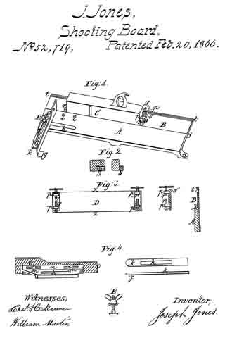
In the drawings, Figure 1 shows the board and the plane as when ready for use. Fig. 2 represents the end of the plane with the peculiarly – formed attachment thereto. Fig. 3 shows the bed-piece to which the plane is connected, with the providings for holding the plane securely thereto; also is shown an end view of the bed-piece and an end view of the shooting – board, Fig. 1. Fig. 4 shows the various parts used in the construction of the stop against which the piece to be planed is held.
The base-board, as is usual, has the part A elevated above the part B, the difference being increased in my improvement to admit under the plane C the bed-piece D, Fig. 3, the edge z of the bed-piece D being fitted to and sliding in the groove y in the edge of the elevated part A of the base-board.
The groove is shown in the end view of the base-board, Fig. 3.
The edge x has a projection, u, on the under side, as shown in the end view in Fig. 3, which slides in the V-shaped groove t. (Seen in the end view of the base-board at Fig. 3.)
On each end of the plane C is affixed a projecting piece, s, Fig. 2, which, when the plane is placed in the bed-piece D, is between the ends of the set-screws r, by which the plane is held down firmly to the bed-piece. The piece s being wider at the bottom than at the top, every turn of the screws r tends to pressing the plane close down to the bed-piece D, the set-screws being attached to the bed-piece by their nuts being formed in the projections p on the bed-piece D.
When necessary varied inclinations of the face of the plane C can be had by inclined bed-pieces, and the same result is attainable by the use of beveled pieces laid on the base-board under the piece to be planed.
The stop against which the board is placed to be planed has a face-piece, o, Fig. 4, has on its back a projecting plate, n, said plate having a flange in which are two slots, through which the two screws on pass into the face-piece o, by which means are provided for the adjustment ofthe face-piece required when planing at different angles.
The under side of the projecting plate it is formed as a groove of the required width to admit the piece k, Fig. 4, upon which the projecting plate n is movable.
The edge view of the piece k shows on the under side a pin, j, which fits the holes i on the base-board, Fig. 1, to keep the stop in the desired place required by various angles, the whole combined stop being secured to the base-board by the thumb-screw E, Fig. 4, which passes through the slots h, (seen in the base-board,) the projecting piece n, and the slide k, the head being below and the nut on the upper side.
In the provisions above described for the adjustment of the parts of a shooting-board necessary for angular planing and tor the steadiness and security of the plane, I do not confine myself to either metal or wood in any of the parts, using the one or the other as the worlrman chooses.
For convenience a projection, g, is attached to the end of the stop face-piece o, to form a support when the piece being planed is of an inconvenient length to be held steady by the hand of the operator.
The placing of a handle upon the side of the plane that is uppermost when performing the operation of shooting joints on the board gives the workman important advantage over the ordinary manner of grasping the body of the plane in the hand.
What I claim, and desire to secure by Letters Patent, is —
The shooting – board constructed and arranged substantially as hereinabove specified, as an improved implement or tool.
JOSEPH JONES.
Witnesses:
CHAS. H. SKINNER,
WILLIAM MARTIN.