No. 60,265 – Improvement In Mitre Planes (John Sawyer) (1866)

[paiddownloads id=”121″]60265


United States Patent Office.


IMPROVEMENT IN MITRE PLANES.
_________________

JOHN SAWYER, OF MORAVIA, NEW YORK.

Letters Patent No. 60,265, dated December 4, 1866.

_________________

SPECIFICATION.

TO ALL WHOM IT MAY CONCERN:

Be it known that I, JOHN SAWYER, of Moravia, in the county of Cayuga, and State of New York, have invented a new and useful Improvement in Plane; and I do hereby declare that the following is a full, clear, and exact description thereof, which will enable others skilled in the art to make and use the same, reference being had to the accompanying drawings, forming part of this speciication, in which —

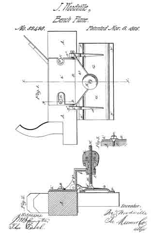
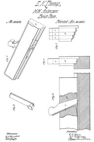
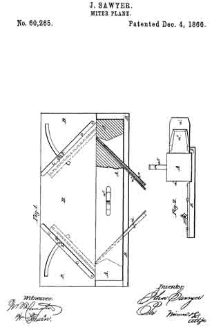
Figure 1 is a top view of my improved plane and guide-plate, part being broken away to show the construction.

Figure 2 is an end view of the same.

Similar letters of reference indicate like parts.

My invention has for its object to furnish an improved apparatus by means of which the ends of mouldings may be out at any desired bevel so as to make a close joint; and it consists, first, in the plane, constructed and arranged as hereinafter more fully described; and, second, in the adjustable guide-plate, in combination with the plane, said guide-plate being constructed and arranged as hereinafter more fully described.

A is the plane, which is furnished with two plane-irons, a1 and a2, placed, one in each end of the plane and inclined in opposite directions, as shown in fig. 1. The cutting edges of these plane-irons, a1 and a2, project at the side of the plane, instead of projecting at the bottom, in the usual manner. The plane-irons a1 and a2 are set in grooves in the body of the plane, and are secured in place by wooden wedges, a3 and a4, in the ordinary way, a space being formed in front of said irons and wedges for the escape of the shavings. The handle, a5, is attached to the central part of the upper side, as shown in fig. 1, and should be of such a form that the plane may be conveniently worked in either direction. B is the guide-plate, in connection with which the plane is used. The face of the plate B is grooved longitudinally near one edge, with a shallow groove of such a size that the lower face or side of the plane, A, may accurately fit into it, as shown in fig. 2, so that it may move in a direct line when operated. The depth of this groove should be such that the upper surface of the plate B may be in a line with the lower corner of the plane-irons, as shown in ig. 2. C are the guide-bars, against which the mouldings are held while being operated upon. These guide-bars, C, are pivoted at their inner ends to the plate B, and they are clamped at any angle to give any desired bevel to the ends ofthe moulding by the screws D and thumb-nuts E. The screws D pass through slots formed in the plate B, their heads fitting into a channel formed on the under side of said plate.

I claim as new, and desire to secure by Letters Patent —

The grooved and slotted plate B and pivoted guide-bars C, when used in combination with the plane A, having its iron, a1 a2, inclined in opposite directions, substantially as described for the purpose specified.

JOHN SAWYER.

Witnesses:
E. E. BROWN,
O. R. VAN ETTEN.

No. 59,498 – Improvement In Carpenters’ Planes (John Woodville) (1866)

[paiddownloads id=”120″]59498


UNITED STATES PATENT OFFICE.

_________________

JOHN WOODVILLE, OF CINCINNATI, OHIO.

IMPROVEMENT IN CARPENTERS’ PLANES.

_________________

Specification forming part of Letters Patent No. 59,498, dated November 6, 1866.

_________________

To all whom it may concern:

Be it known that I, JOHN WOODVILLE, of Cincinnati, in the county of Hamilton and State of Ohio, have invented a new and useful Improvement in Jointing-Planes; and I do hereby declare that the following is a full, clear, and exact description thereof, which will enable others skilled in the art to make and use the same, reference being had to the accompanying drawings, forming part of this specification, in which —

Figure 1 is a side view of a plane with my improvement attached. Fig. 2 is a cross-section of the same, taken through the line x x, Fig. 1. Fig. 3 is a detail sectional view of the same, taken through the line y y, Fig. 1.

Similar letters of reference indicate like parts.

My invention has for its object to furnish an improved jointing-plane, by means of which the edge of a board may be made square, or may be beveled at any desired angle; and it consists in the supporting angular plate, the adjustable hinged guide-plate, the adjusting-screw, bush-nut, wrench, and lock-nut, in combination with each other and with the stock or frame of the plane, when said parts are constructed and arranged as hereinafter more fully described.

A is the plane-stock, about the construction of which there is nothing new. B is the supporting-plate, which consists of three portions, b1 b2, and b3. The part b1 is attached to the side of the plane-stock A by two bevel-headed screw-bolts, C and D, which pass through beveled slots E and F in the said part b1 of the plate B, as shown in Fig. 1. The slots E and F are beveled in two ways: first, their edges are beveled so as to fit upon the beveled underside of the heads of the bolts C and D, as shown in Fig. 3, and, second, they are beveled or made wedge-shaped, so as to clamp the bolts C and D, and thus be held securely in place. The rear end of the slot E is enlarged, so as to permit the head of the bolt C to pass through it, but the slot F is cut through the edge of the plate, as shown in Fig. 1. The part b2 stands at right angles to the part b1, as shown in Figs. 1 and 2. The part b3 projects from the upper edge of the part b2, and is parallel with the part b1, as shown in Fig. 2. The part b3 is made in the form of an isosceles triangle, and has a hole made through its apex, which hole is countersunk or rounded out on its upper side, for the purpose hereinafter mentioned.

The plate B is strengthened by having a flange cast upon its edge, as shown in Figs. 1 and 2.

G is the sliding guide-plate, the side edges of which project downward, so as to form ribs or runners g1, upon which it slides along the surface of the timber being operated upon, and insures the plate G from rocking, and gives a steady movement to the plane. g2 and g3 are projecting ears or arms cast upon the plate G, by means of which said plate is pivoted to the plate B. The pivoting-point g4, attached to the ear g3, is made solid therewith; but the pivoting-point g5, attached to the ear g2, is removable, being the point of a screw passing through the said ear, as shown in Fig. 1. These points g4 and g5 enter and work in sockets formed in the edge of the part b2 of the plate B, as shown in Fig. 1.

The ears g2 and g3 are made with a shoulder, as shown in Fig. 2, so that the inner edge of the plate G may be as low or a little lower than the upper corner of the edge of the plane-iron, so that the whole edge of the board may be smoothly cut.

g6 are two ears, cast upon the upper surface of the plate G, between which the end of the screw H is pivoted by a pin passing through the said ears and the said end of the screw, as shown in Fig. 2.

I is a bush-nut, which passes up through the hole in the part b3 of the plate B, before described, and through which the screw H passes. J is a wrench, which fits upon the upper end of the bush-nut I, and which has a feather formed upon its inner surface, which feather enters a slot or groove in the side of the said bush-nut I, so that the said nut may be raised or lowered by turning the wrench J. The nut I is made with a flange on its lower end, and the lower end of the wrench J is rounded off, so as to fit into rounded-out parts of the hole through the plate B at whatever angle the screw H may stand.

K is a lock-nut, which screws down upon the screw H, and locks the wrench J, plate B, and bush-nut I firmly together, the plate B being clamped between wrench J and the flange of the nut I, as shown in Fig. 2.

Into the lower face of the nut K is cut a deep circular groove, as shown in Fig. 2, into the bottom of which is placed a rubber or other elastic spring, L. M is a metal ring, placed in the said groove upon the said spring L. When the nut K is screwed down upon the wrench J the end of the ring M comes in contact with the face of the said wrench J, and holds the parts with an equal pressure at whatever angle the screw H may stand.

By this construction and arrangement the guide plate G may be set at any angle with the face of the plane, so as to give any desired bevel to the jointed edge of the board operated upon, and the parts are all held firm and immovable while the plane is being used, thus insuring a perfectly true joint.

I claim as new and desire to secure by Letters Patent —

The hinged screw-rod H, in combination with the parts D G, and provided with the flanged nut I, wrench J, and lock-nut K, when arranged with the jointing-plane herein described, substantially as and for the purpose specified.

JOHN WOODVILLE.

Witnesses :
ALEXANDER MCDONALD,
THOMAS PALMER, Jr.

No. 56,651 – Improvement In Cabinet-Makers’ Scrapers (Frank A. Williams, John H. Williams And Daniel G. Williams) (1866)

[paiddownloads id=”119″]56651


UNITED STATES PATENT OFFICE.

_________________

FRANK A. WILLIAMS, JOHN H. WILLIAMS, AND DANIEL G. WILLIAMS, OF CINCINNATI, OHIO.

IMPROVEMENT IN CABINET-MAKERS’ SCRAPERS.

_________________

Specification forming part of Letters Patent No. 56,651, dated July 24, 1866.

_________________

To all whom it may concern:

Be it known that we, FRANK A. WLLLIAMS, JOHN H. WILLIAMS, and DANIEL G. WILLIAMS, all of Cincinnati, Hamilton county, Ohio, have invented a new and useful Cabinet-Maker’s Scraper; and we do hereby declare the following to be a full, clear, and exact description thereof, reference being had to the accompanying drawings, making part of this specification.

The scraper in customary use by cabinet-makers, coach-makers, and other finishers of wood-work consists, as is well known, of a simple blade of steel having a turned or upset and sharpened edge. This blade, being grasped by the workman between the fingers and thumbs of both hands is operated by being thrust forcibly over the work. This operation, besides blistering the hands of the operator, so quickly heats up the tool as to soon oblige him to lay it down. These inconveniences we wholly avoid by mounting the scraper proper in a suitably-formed handle of wood or other non-conducting material. We also, in addition to said provision, apply mechanical devices whereby the tool can be made to scrape with greater or less fineness independently of the degree of force or pressure exerted.

Figure 1 is a perspective view of a scraper embodying our invention. Fig. 2 is a transverse section taken at mid-length of the instrument. Fig. 3 shows the parts of the scraper detached. Fig. 4 represents forms of bits adapted for operation on hollow and on round work respectively.

A represents the bit or scraper proper. B is a stock or handle of wood, suitably excavated to receive the bit and a mouth-piece, C.

The bit A, being sprung into the notches b b’, is adjusted toward the mouth-piece, so as to shave with any desired degree of fineness, by means of a set-screw, D.

Thumb-screws E E’ serve to secure the mouth-piece C, and, through it, the bit A.

On slackening of the mouth-piece C by retraction of the screws E E’ the bit is so far released as to be readily shifted, so as to cut rank or fine. When adjusted to cut fine, it should also, by means of the screw D, be set proportionally near to the mouth-piece. On the retraction of the screw D, the spring of the bit itself draws it automatically away from the mouth-piece. The mouth-piece has a throat or excavation, c, through which the shavings escape.

During operation the heads of the thumb-screws E E’ serve as a brace or abutment fbr the thumbs of the operator.

We have selected for illustration a scraper adapted for flat work; but the device is equally applicable for curved work, the bit and handle being modified in each case as judgment or fancy may indicate.

We claim herein as new and of our invention —

A scraper consisting of the blade A, stock B b, mouth-piece C, set-screw D, and clamping-screws E E’, all constructed and arranged substantially as and for the purpose herein specified.

In testimony of which invention we hereunto set our hands.

FRANK A. WVILLIAMS.
A JOHN H. WILLIAMS.
DNL. G. WILLIAMS.

Witnesses:
GEO. H. KNIGHT,
JAMES H. LAYMAN.

No. 55,599 – Improvement In Spokeshaves (Leonard Bailey) (1866)

[paiddownloads id=”118″]55599


UNITED STATES PATENT OFFICE.

_________________

LEONARD BAILEY, OF BOSTON, MASSACHUSETTS.

IMPROVEMENT IN SPOKESHAVES.

_________________

Specification forming part of Letters Patent No. 55,599, dated June 19, 1866.

_________________

To all whom it may concern:

Be it known that I, LEONARD BAILEY, of Boston, in the county of Suffolk and State of Massachusetts, have invented an Improved Spokeshave; and I do hereby declare the same to be fully described in the following specification, and represented in the accompanying drawings, of which —

Figure 1 denotes a top view, Fig. 2 a front elevation, Fi g. 3 a transverse section, and Fig. 4 a longitudinal section, of it.

In carrying out my invention I construct the stock of the spokeshave in two separate parts. and so that each of its handles shall be divided into two parts length wise, in manner as shown at a a’ in Figs. 1, 2, and 4. The two lowermost parts, a’ a’, of the handles I combine in one piece with the cutter rest or supporter — that is, so as to extend in opposite directions therefrom — and I also combine the other two or upper parts, a a, of the handles with the adjustable shank-piece c, so as to be in one piece therewith and to extend in opposite directions from it, in manner as exhibited in the figures.

The cutter or shave iron d, resting on the part b, I secure thereto by means of a clamp-bar, e, which is arranged on the cutter and directly over the part b, and is held in place (and so as to conbine the cutter to the said part D) by means of two screws, f f, which go through the lower parts of the handles and screw through the said clamp-bar e, each of such screws being arranged at right angles, or thereabout, with the lower or bearing surface of the part b.

Furthermore, the clamp-bar is caused, near its ends, to abut against two shoulders, i i, formed in or on the stock. These shoulders are arranged in front of the clamp-bar, and not only serve to prevent the downward strain of the screws from breaking the said screws, but co-operate with the screws in setting the bar closely against the cutter or shave-iron, so as to confine it firmly to its bed.

The parts a a touch the parts a’ a’ simply at or near their extremities, the same being in order that such parts a a, with the extension portion c, may constitute a bow or curved spring, to raise the said portion relatively to the cutter, and so as to increase the throat of the implement.

The screws f f are to extend through the parts a a, and screw into nuts g g, so applied to them as to act against the said parts a a, the said nuts and screws serving to effect a counter-movement of the part c, for the purpose of disconnecting the throat of the spoke shave.

The arrangement of the screws f f, the shoulders i i, and the clamp-bar e relatively to the cutter or iron d, the bed on which it rests, and the bottom, surface of the part b renders the clamp very efficient in holding the cutter down to the bed, however the clamp, by the action of the screws, is driven downward in a direction which is at an obtuse angle, its surface in contact with the plane-iron. The screws f f, by their arrangeinent, perform the duty not only of holding the clamp down upon the plane iron, but of co-operating with their nuts in springing the upper parts, a a, ot the handle, so as to regulate the distance of the throat-piece c from the plane-iron.

What I claim in the above improved spoke-shave is as follows:

1. The combination of the screws f f and nuts g g, or their equivalents, with the clamp-bar e, and with the stock divided length wise into two parts or portions, constructed substantially in manner and so as to operate as described.

2 The arrangement of the clamp-bar e with the screws f f and nuts g g, and with the stock divided lengthwise into two parts or portions, constructed substantially in manner and so as to operate with the said screws and nuts, substantially as set forth.

3. The combination and arrangement of the shoulders i i with the screws f f, the clamp-bar e, the cutter d, and bed b, or the stock, substantially as set forth.

LEONARD BAILEY.

Witnesses:
R. H. EDDY,
FREDERICK CURTIS.

No. 55,207 – Improvement In Carpenters’ Planes (Georg Müller) (1866)

[paiddownloads id=”117″]55207


UNITED STATES PATENT OFFICE.

_________________

GEORG MÜLLER, OF NEW YORK, NY., ASSIGNOR TO HIMSELF AND HENRY JOSEPH BANG, OF SAME PLACE.

IMPROVEMENT IN CARPENTERS’ PLANES.

_________________

Specification forming part of Letters Patent No. 55,207, dated May 29, 1866.

_________________

To all whom it may concern:

Be it known that I, GEORG MÜLLER, of the city, county, and State of New York, United States of America, have invented certain new and useful Improvements in Carpenters’ Planes 5 and I do hereby declare that the same is fully described and represented in the following specification and the accompanying drawings, of which —

Figure 1 is a top view of a carpenter’s plane with my invention applied to it. Fig. 2 is a side elevation. Fig. 3 is a vertical section. Fig. 4 is an edge view of the bit-iron; Fig. 5, an edge view of the cap-iron or base of the sliding box; Fig. 6, a view of the sliding box with its slots; Fig. 7, a view of the sliding box in connection with the joint-pin, forked prize-piece or carrier, and set-screws; Fig. 8, an edge view of said prize-fork, and Fig. 9 a plan of same.

This invention relates to a carpenter’s plane in which the plane-iron or bit is so placed in relation to the plane-stock that the cutting-edge of the bit shall be forward of or projected beyond the forward end of the plane-stock, for the purpose of planing into the angles of stationary or framed carpenter-work, whether of square or molded form, and thus enable the carpenter to rent his doors, window-sashes, &c., to their frames with facility and dispatch; and, besides this, the cap-iron is so applied to the bit and to an adjustable or sliding box, which is pivoted in the plane-stock, as to render the plane-irons or cutters capable of the nicest adjustment and stability in relation to the plane-stock by means of a carrier or prize-fork within the said box and its set-screws.

Having described the nature of my invention, I will now explain its construction and mode of operation.

In the drawings, A is the plane-stock; B,the handle, and O the plane»iron or cutting-bit. D is the cap-iron, with its lips or projections d d, for reception of the box E. The box E has slots e e, through which the joint-pin G passes, and contains a forked carrier, F, the said carrier having holes through the arms f f for reception of the joint-pin or pivot G, which passes through the said arms f f, the box E, and the plane-stock A. The carrier is sustained and stopped at its opposite end by set-screws g g h, as shown in Fig. 7. There is also a thumb or clamping screw, I, which passes through the box E, between the forked arms of the carrier F, and abuts against the cap-plate D, for the purpose of bracing the irons G and D against the plane-stock A. The front end of the plane-stock, A’, or that part of it in front of the bit G, which, with the plane-stock A, forms the throat a’, I make of iron, steel, or other metal, of the form shown by the red line a’ a’, if desired. The bit C tapers toward its cutting end, and has a boss, x, on its outer end to aid in adjusting the same.

The operation of my invention is very simple, and is as follows: In the first place, I put the bit C in the throat a of the plane-stock A. I next set the forked prize-piece F within the box E, and insert the set-screws g g and retaining-screw It in the box and carrier. I then screw the clamping-screw I through the box, so as to abut against the cap-plate D. I now set the box on the said cap-plate, between the lips d d, and the box, thus prepared, I place in the throat ct of the plane-stock A, on the bit C, and I pass the joint-pin or pivot G through the iron throat a of the plane-stock, through the box E, and the carrier F.

To adjust the cutting-irons in relation to each other and to the plane-stock in a longitudinal direction will be simply to turn the screws g g, when the cap D will be carried by the box E in the direction of the mouth of the plane; or, by a reverse motion of the screws, the said cap will be carried back from the said mouth because of the carrier F being held by the joint-pin G; and should a transverse adjustment of the irons be necessary, the same can be done by slackening one of the screws g and screwing the other up. Now that the irons are properly adjusted to hold the same firmly in position, I clamp the screw I and the bearing-screw lt, when my improved plane is ready for operation.

It will be seen from the above that in the application of my invention to a plane-stock the box E is made a lever, of which the joint-pin G is the fulcrum, and the power being applied through the clamping-screw I, the pressure is exerted against the cap-plate D and the bit C, in consequence of which the said pressure will be equally distributed on that portion of the surface of the throat of the plane on which the bit C rests, and for which reason the plane-stock at its mouth will not become swollen or crushed down in rear of the bit and below the surface of the face of the plane, as is the case with the plane for which Letters Patent of the United States were granted to me on the 9th of October, 1865, in which the strain or pressure on the bit C, by means of the screw I, is brought to bear on the mouth of the plane-stock, crushing down the mouth of the plane in rear of the bit, thus rendering my previous invention inoperative, and to remedy this defect prompted me to produce my present invention, which I claim to be an improvement on the former.

Having described my invention, what I claim, and desire to secure by Letters Patent, is —

The sliding box E, with clamping-screw I, and the forked prize-piece F, in combination with the cap-plate D and bit C, together with placing the same in the throat a, or forward end of the plane-stock, substantially as and for the purposes set forth and described.

In testimony whereof I have hereunto set my signature.

GEORG MÜLLER.

Witnesses :
HENRY J. BANG,
A. NEILL.

No. 52,173 – Tools For Making Lighters (Albert Kleinschmidt And Francis Schlater) (1866)

[paiddownloads id=”112″]13957


UNITED STATES PATENT OFFICE.

_________________

ALBERT KLEINSCHMIDT AND FRANCIS SCHLATER, OF PHILADELPHIA, PENNSYLVANIA.

IMPROVEMENT IN TOOLS FOR MAKING LIGHTERS.

_________________

Specification forming part of Letters Patent No. 52,173, dated January 23, 1866.

_________________

To all whom it may concern:

Be it known that I, ALBERT KLEINSCHMIDT AND FRANCIS SCHLATER, of Philadelphia, Pennsylvania, have invented an Instrument for Making Lighters; and we do hereby declare the following to be a full, clear, and exact description of the same, reference being had to the accompanying drawings, and to the letters of reference marked thereon.

Our invention consists of a plane having a longitudinal groove, a diagonal cutter, and diagonal groove, the whole being arranged, substantially as described hereafter, so as to cut from a strip of wood coiled shavings of a tapering form, applicable to the lighting of cigars, &c.

In order to enable others to make and use our invention, we will now proceed to describe its construction and operation.

On reference to the accompanying drawing, which forms a part of this specification, Figure 1 is a side view of our plane for making lighters; Fig. 2, an inverted plan view, with parts of the plane removed; Fig. 3, a transverse vertical section on the diagonal line 1 2, Fig. 2, and Fig. 4 a transverse section on the line 3 4, Fig. 1.

Similar letters refer to similar parts throughout the several views.

A represents the body of the plane, which is similar, as regards external form, to ordinary planes, and is provided with the usual handle a. A cutter, B, passes through an opening in the body of the plane, and is secured by a wedge, C, the cutter being arranged diagonally and at the near edge of a diagonal groove, j, formed in the under side of the body of the plane. (See Fig. 2.)

It should be understood that the opening in the body of the plane for the reception of the cutter and wedge is entirely filled by the latter.

To the under face of the body of the plane are secured two strips, d and d’, so as to form a longitudinal groove, e, one of these strips covering part of the diagonal groove f, and thereby converting the latter into an opening, h, on one side of the plane, Fig. 1.

In operating with the above-described tool a piece of pine or other wood as free as possible frorn knots is selected, the piece being of the same width as or a trifle narrower than the width of the groove e between the strips d d’. The piece of wood is properly secured edge upward, and the operator, placing his plane so that the edge of wood is situated between the grooves, proceeds to remove shaving after shaving. Each shaving, as it is being cut from the wood, will, owing to the diagonal position of the knife and the groove f pass through the opening h in the form of a tapering coil, as seen at x, Fig. 3. The coiled shavings thus formed retain their uniform shape and neat appearance, and are especially useful for lighting cigars, &c.

We claim as our invention and desire to secure by Letters Patent —

The within-described plane, with its longitudinal groove e, diagonal cutter B, and diagonal groove j, the whole being arranged substantially as and for the purpose herein set forth.
In testimony whereof we have signed our names to this specification in the presence of two subscribing witnesses.

ALBERT KLEINSCHMIDT.
FRANCIS SCHLATER.

Witnesses:
CHARLES E. FOSTER,
JOHN WHITE.

No. 52,478 – Improvement In Saw Rabbet Planes (Daniel D. Whitker) (1866)

No. 52,478 – Improvement In Saw Rabbet Planes (Daniel D. Whitker) (1866)

[paiddownloads id=”113″]52478


UNITED STATES PATENT OFFICE.

_________________

DANIEL D. WHITKER, OF HUDSON, NEW YORK.

IMPROVEMENT IN SAW-RABBET PLANES.

_________________

Specification forming part of Letters Patent No. 52,478, dated February 6, 1866.

_________________

To all whom it may concern:

Be it known that I, DANIEL D. WHITKER, of the city of Hudson, in the county of Columbia and State of New York, have invented a new and useful Tool or Instrument for Rabbeting and Plowing or Grooving Lumber, which I call or denominate the “Saw-Rabbet;” and I hereby declare that the following is a clear and exact description of the construction and operation of the same, reference being had to the annexed drawings, making a part of this specification, in which —

Figure 1 is a perspective view. Fig. 2 is a longitudinal or side elevation; and Fig. 3 is a transverse section or end view.

The nature of my invention consists in combining an adjustable saw with an adjustable fence or gage, both being attached to a stock with handle similar to a plane, forming together a tool combining the properties of the joiner’s plow and fillister.

To enable those skilled in the art to make and use my invention, I will proceed to describe its construction and operation.

I construct my saw-rabbet with stock and handle similar to a plane, but without mortise for the iron. To the outside of this stock I attach, by means of the screws a a’ a”, an adjustable saw, A. The slots s s’ s” in the saw enable it to be set up or down, so as to cut any desired depth. This saw may be of any required thickness for inserting panels, or by means of the adjustable fence or gage C, attached to the bottom ofthe stock B by the screws b b’ through the slots c c’, may be made to saw one, two, or more cuts or grooves at any desired distance from the edge for rabbeting, or a part for grooving, and the intermediate wood removed by a chisel or ordinary rabbet-plane. But the saw-rabbet is specially adapted to cutting grooves for inserting the rubber weather-strip, and the only tool that can be used advantageously for that purpose. In addition to the foregoing it will do all the work of both the fillister and the plow. lt can also be easily converted into a useful tool for rabbeting on curves or circles by setting out one or both ends ofthe saw by means of curved wedges or thumb-screws. A steel spring fence or gage may then be employed and be set out with the saw.

The stock to which the saw is attached may be of wood or metal. The friction-rolls o o’ o’
in the front edge ofthe gage rest or fence are employed to lessen the friction in operating the saw-rabbet.

The operation of this instrument needs no explanation. It is employed precisely like the fillister and plow, the operation of which is well understood by all carpenters and joiners, and indeed by all who have any acquaintance with these tools.

What I claim as my invention, and desire to secure by Letters Patent of the United States, Is —

Combining and arranging the adjustable saw A with the adjustable gage-rest G, substantially in the manner and for the purpose herein set forth.

DANIEL D. WHITKER.

Witnesses:
FRANK A. MACY,
WILLARD S. WOOD.

No. 52,719 – Improvement In Carpenter’s Shooting Boards (Joseph Jones) (1866)

[paiddownloads id=”114″]52719


UNITED STATES PATENT OFFICE.

_________________

JOSEPH JONES, OF NEWARK, NEW JERSEY.

IMPROVEMENT IN CARPENTERS’ SHOOTING-BOARDS.

_________________

Specification forming part of Letters Patent No. 52,719, dated February 20, 1866.

_________________

To all whom it may concern:

Be it known that I, JOSEPH JONES, of the city of Newark, in the county of Essex and State of New Jersey, have invented certain Improvements in the Implement technically termed by workers in wood a “Shooting-Board” and I do hereby declare the following to be a full and exact description of the same, reference being herein had to the drawings accompanying this specification, making part of the same.

The nature of my improvement consists in attachments which adapt the board to the shooting or planing at any required angle in the direction required by the grain of the wood, and in securing the plane to the board in a way to ease its motion, at the same time rendering it more stable or solid at its work.

In the drawings, Figure 1 shows the board and the plane as when ready for use. Fig. 2 represents the end of the plane with the peculiarly – formed attachment thereto. Fig. 3 shows the bed-piece to which the plane is connected, with the providings for holding the plane securely thereto; also is shown an end view of the bed-piece and an end view of the shooting – board, Fig. 1. Fig. 4 shows the various parts used in the construction of the stop against which the piece to be planed is held.

The base-board, as is usual, has the part A elevated above the part B, the difference being increased in my improvement to admit under the plane C the bed-piece D, Fig. 3, the edge z of the bed-piece D being fitted to and sliding in the groove y in the edge of the elevated part A of the base-board.

The groove is shown in the end view of the base-board, Fig. 3.

The edge x has a projection, u, on the under side, as shown in the end view in Fig. 3, which slides in the V-shaped groove t. (Seen in the end view of the base-board at Fig. 3.)

On each end of the plane C is affixed a projecting piece, s, Fig. 2, which, when the plane is placed in the bed-piece D, is between the ends of the set-screws r, by which the plane is held down firmly to the bed-piece. The piece s being wider at the bottom than at the top, every turn of the screws r tends to pressing the plane close down to the bed-piece D, the set-screws being attached to the bed-piece by their nuts being formed in the projections p on the bed-piece D.

When necessary varied inclinations of the face of the plane C can be had by inclined bed-pieces, and the same result is attainable by the use of beveled pieces laid on the base-board under the piece to be planed.

The stop against which the board is placed to be planed has a face-piece, o, Fig. 4, has on its back a projecting plate, n, said plate having a flange in which are two slots, through which the two screws on pass into the face-piece o, by which means are provided for the adjustment ofthe face-piece required when planing at different angles.

The under side of the projecting plate it is formed as a groove of the required width to admit the piece k, Fig. 4, upon which the projecting plate n is movable.

The edge view of the piece k shows on the under side a pin, j, which fits the holes i on the base-board, Fig. 1, to keep the stop in the desired place required by various angles, the whole combined stop being secured to the base-board by the thumb-screw E, Fig. 4, which passes through the slots h, (seen in the base-board,) the projecting piece n, and the slide k, the head being below and the nut on the upper side.

In the provisions above described for the adjustment of the parts of a shooting-board necessary for angular planing and tor the steadiness and security of the plane, I do not confine myself to either metal or wood in any of the parts, using the one or the other as the worlrman chooses.

For convenience a projection, g, is attached to the end of the stop face-piece o, to form a support when the piece being planed is of an inconvenient length to be held steady by the hand of the operator.
The placing of a handle upon the side of the plane that is uppermost when performing the operation of shooting joints on the board gives the workman important advantage over the ordinary manner of grasping the body of the plane in the hand.

What I claim, and desire to secure by Letters Patent, is —

The shooting – board constructed and arranged substantially as hereinabove specified, as an improved implement or tool.

JOSEPH JONES.

Witnesses:
CHAS. H. SKINNER,
WILLIAM MARTIN.

No. 53,698 – Improvement In Spokeshaves (John G. Steiger) (1866)

[paiddownloads id=”115″]53698


UNITED STATES PATENT OFFICE.

_________________

JOHN G. STEIGER, OF CLEVELAND, OHIO.

IMPROVEMENT IN SPOKESHAVES.

_________________

Specification forming part of Letters Patent No. 53,698, dated April 3, 1866.

_________________

To all whom it may concern:

Be it known that I, J. G. STEIGER, of Cleveland, in the county of Cuyahoga and State of Ohio, have invented certain new and useful Improvements in a Box-Scraper and Draw-Shave Combined; and I do hereby declare that the following is a full and complete description of the same, reference being had to the accompanying drawings, making a part of this specification, in which —

Figure 1 is a top view. Fig. 2 is a view of the under side. Fig. 3 is a transverse section in the direction of the lines x x Figs. 1 and 2.

Like letters of reference refer to like parts in the several views.

My improvement relates to a combined box-scraper and draw-shave, constructed and arranged as hereinafter described.

The draw-shave consists of an elongated metal piece, the ends A of which are shaped into handles, as represented in Figs. 1 and 2. The middle part, A’, is formed into a neck with shoulders b on each side.

B is the blade or scraper, the ends of which it into the shoulders, as shown at e.

C is a clamp fitting onto one side of the blade, holding it in place, being secured or clamped on by means of thumb – screws d, screwed through the shoulders b into the ends of the clamp, which come against one side of the shoulders. The under side, C’, of the clamp and A” of the neck, where the edge of the blade B comes through, are flat and smooth, as seen in Figs. 2 and 3.

The blade B is inclined in its position, as represented in Fig. 3, between which and the neck A’, transversely, and between the shoulders b, longitudinally, the throat D is formed, where the scrapings and shavings pass up through as it is used.

The handles A, neck A’, and shoulders b are east in one entire piece, the clamp C like-wise, so that it is very simple and economical in its construction.

The blade is made of one piece, and can be set in or out more or less, as may be desired, by simply adjusting the set-screws; or a new blade can be put in when one is worn out.

When used for a draw-shave it is of the shape represented in Figs. 1 and 2; but for a box-scraper the handles should be turned up or elevated a little, so that the hands will not come in contact with the board as it is drawn over it.

What I claim as my improvement, and desire to secure by Letters Patent, is —

The special construction of the cast handle and clamp,with the shoulders b, formed between the clamp and handle, blade B, and set-screws d, and operating substantially as described.

JOH. G. STEIGER.

Witnesses:
W. H. BURRIDGE,
FRANK ALDEN.

No. 53,899 – Planes For Making Blind Slats (Enoch K. Thomas And Hans H. Andresen) (1866)

[paiddownloads id=”116″]53899


UNITED STATES PATENT OFFICE.

_________________

ENOCH K. THOMAS, OF ROCK ISLAND, ILLINOIS, AND HANS H. ANDRESEN, OF DAVENPORT, IOWA.

IMPROVEMENT IN PLANES FOR MAKING BLIND-SLATS.

_________________

Specification forming part of Letters Patent No. 53,899, dated April 10, 1866.

_________________

To all whom it may concern:

Be it known that I, ENOCH K. THOMAS, of Rock Island, Rock Island county, and State of Illinois, and HANS HEINRICH ANDRESEN, of Davenport, Scott county, State of Iowa, have invented a new and useful Plane for Making Window-Shade Slats; and we do hereby declare that the following is a full, clear, and exact description thereof, reference being had to the accompanying drawings, making a part of this specification, in which —

Figure 1 is a perspective view of a single-iron slat-plane. Fig. 2 is a perspective view of the cutter or plane-iron detached from the plane-stock. Fig. 3 is a sectional view, showing the mode of cutting slats from a piece of wood. Fig. 4 is a front end view of the single iron plane. Fig. 5 is a front end view of a plane-stock which is adapted for receiving three cutters.

Similar letters of reference indicate corresponding parts in the several figures.

The object of this invention is to produce slats for wooden window-shades of a uniform thickness and width by means of a plane which is so constructed that the slats pass freely through the plane-iron between the sole of the plane-stock and its bottom cutter without liability of becoming broken or otherwise injured, as will be hereinafter described.

To enable others skilled in the art to understand Our invention, we will describe its construction and operation.

The plane which we have represented in Figs. 1, 2, 3, and 4 of the drawings is intended for cutting one slat at a time from a piece of wood. The sole of this plane has three steps, a a’ a”. The intermediate step, a, is equal in width to the width of the slats which are produced, and the vertical surface of the step a2 is intended to form a side guide for the plane-stock in its forward movements over the piece of wood from which the strips or slats are cut.

The cutter or plane-iron B has a cutting-lip, b, on its lower end and a cutting-lip, c, formed on one side — that side which is nearest the step a. This plane-iron has an opening, d, through it, which should be equal in width to the width of the slats that are cut, so that as the slats that are severed from the piece of wood by the horizontal and vertical cutting-lips b c these slats will pass freely through the plane-iron without being materially bent out of a straight line, as shown in Fig. 3.

The plane-iron B is secured at the required pitch in its stock A by means of a wedge, C, in the usual manner of securing common plane-irons into their stocks, and the cutting-lip b projects below the sole of the stock a distance which is equal to the thickness desired for the slats.

It will be necessary to form a depression, e, just in rear of the cutter lf, so as to allow of the slats rising over this cutter; but as this cutter can be made quite thin, it will not be necessary to form much of a depression in the sole of the stock.

To obviate a gouging action of the cutting-lip b, which would cause the plane to work very hard and produce slats of an uniform thickness, the space between the cutting-edge of said lip and the lower end of the wedge C should not be greater than the required thickness ofthe slats. The space back of this point for a short distance may be increased, as above mentioned.

It will be seen from the above description of our plane or slat-cutter that the slat is held firmly down upon the surface of the piece of wood during the operation of producing it, and that the only elevation of the slat from such surface takes place at the cutter b, which must pass under the slat; but while this is the case the slat which is being cut will he held down in rear of said cutter, so that it cannot be broken or split.

We do not confine our invention to a single-iron plane for cutting or producing slats, as the stock may be adapted for receiving two, three, or more cutters, arranged as shown in Fig. 5, so that a number of slats can be cut at each forward movement of the plane over the piece of stuff.

It is obvious that this plane may be secured to a bench-vise or to any other object and the stuff moved over it instead of moving the plane by hand over the fixed stuff ; or, if desirable, the plane or the stuff from which the slats are cut may be moved by machinery without changing the principle of our invention. One great advantage of our invention is that we can cut slats from the side or edge of a board or log without the necessity of resawing and previously dressing the stuff, and this can be done with stuff of any thickness or width.

Were not our cutter provided with the two cutting-edges described, the splints or slats could not be cut from a bolt or plank of a greater thickness than the length of the cutting-edge of the cutter or plane-iron. This will be evident from an inspection of the drawings illustrating our mode of cutting strips or splints from a large bolt or log.

By arranging a series of cutters on a plane-stock, stepped as shown, we can, after having cut a series of splints from the bolt, bring two cutters into use, and after we have cut another series of splints by each of the two cutters we can bring into use a third cutter in connection with the two which are already brought into use, and so on, according to the number of steps and cutters provided on the plane-stock. To bring the different cutters into use a channel in the wood must be made tbr a succeeding cutter by a preceding cutter, as must be evident. Thus by our invention a series of splints may be cut at one time from a bolt which is of much greater thickness than the length of the edge of either of the cutters after channels adapted for the respective cutters are cut in the bolt.

Having thus described our invention, what we claim as new, and desire to secure by Letters Patent, is —

1. The construction of a cutter for producing slats with two cutting-edges and an opening through the shank of the cutter for the passage ofthe slats, substantially as described.

2. The combination of one or more slat-cutters, constructed substantially as described, with a plane-stock having its sole stepped substantially as set forth.

ENOCH K. THOMAS.
HANS HEINRICH ANDRESEN.

Witnesses:
HANS ARBAHR,
HANS KÜHAER.