No. 285,546 – Bench-Plane (Leonard Bailey) (1883)

[paiddownloads id=”342″]285546


UNITED STATES PATENT OFFICE.

_________________

LEONARD BAILEY, OF HARTFORD, CONNECTICUT.

BENCH-PLANE.

_________________

SPECIFICATION forming part of Letters Patent No. 285,546, dated September 25, 1883.
Application filed July 11, 1883. (No model.)

_________________

To all whom it may concern:

Be it known that I, LEONARD BAILEY, of Hartford, in the county of Hartford and State of Connecticut, have invented certain new and useful Improvements in Planes; and I do hereby declare that the following is a full, clear, and exact description thereof, whereby a person skilled in the art can make and use the same, reference being had to the accompanying drawings, and to the letters of reference marked thereon.

Like letters in the figures indicate the same parts.

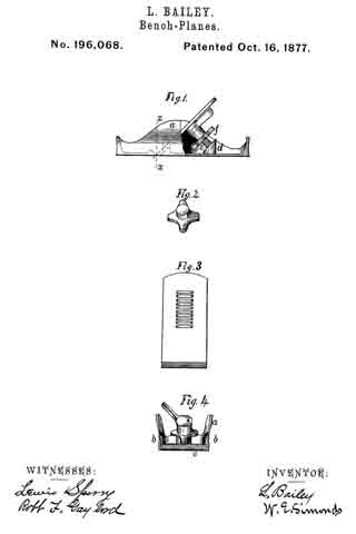
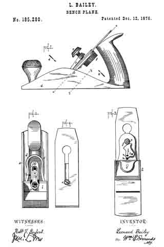
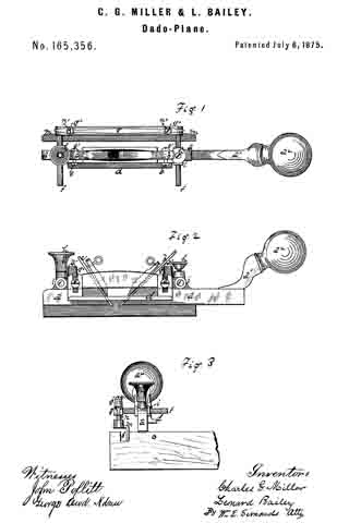
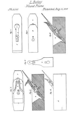
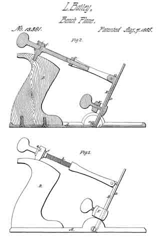
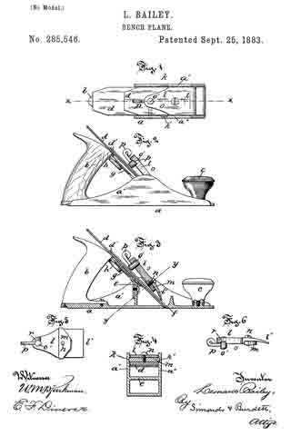
Figure 1 is a plan view of the upper side of the plane in a line at right angles to the plane of the iron parts broken away. Fig. 2 is a side view of a plane having my improvement. Fig. 3 is a view in central vertical longitudinal section of same on line x x of Fig. 1. Fig. 4 is a view in cross-section on plane denoted by line y y of Fig. 3. Fig. 5 is a detail bottom view of my improved clamp. Fig. 6 is a detail side view of same.

My invention relates to the class of devices used for holding the cutting-iron of a plane in place in the body in such manner as to allow of the ready adjustment of the iron lengthwise in the usual manner.

It consists in the special combination and arrangement ofthe parts making up the clamping device, and in the method of fastening it in the plane-body.

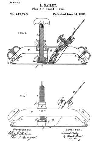
In the accompanying drawings, the letter a denotes the plane-body as a whole, formed of any ordinary material, as iron; b and c, handles for grasping and using the plane; d, a cutting-iron of ordinary form arranged upon a bed, e, so as to be protruded from the usual mortise, f, by means of any slow-motion device, as a series of intermeshing cog-wheels, g, operated by means of the thumb-screw h.

There is nothing new or original with me in the parts described thus far, and no further description is needed for one skilled in making or using planes.

In the style shown the plane-body a is of iron, with the upright side flanges, a’ a”, and on the inner side of each of these danges the corresponding mortises, k k’, are made substantially parallel in direction with the plane of the cutting-iron, and a short distance above or in front of its upper surface.

The letter l denotes the clamp-plate, having the foot l’, adapted to bear upon the face of the cutting-iron, or on the cap-iron d’, placed just over and upon it, and having arranged upon its under side, just in front of a transverse shoulder, the laterally-projecting arm m, adjustably attached to the clamp-plate by means of the screw n. This arm is so arranged that its opposite ends fit into and move in the mortises in the flanges, and form the fulcrum on which the clamp works in fastening the irons in place. In the upper end of the clamp-plate is placed a clamp, o, consisting of a shaft, o’, which is rotarily secured with its lower end bearing upon the cutting-iron about on its center line, and bears the lever p, which extends beyond the edges of the clamp-plate, and operates in connection with the face-cam r on its under side.

The particular object of my invention is to secure a firm and even bearing for the foot of the clamp upon the irons under it, to provide simple means for regulating the pressure of the clamp at will, and yet have it constant for any given set of irons, and have all the requisite parts simple in form, combination, and operation.

The arm m is loosely attached to the clamp-plate, so that the foot of the latter may find a bearing for its whole length on the iron under it, and the ends of the arm at the same time bear upon the sides of the mortises when the clamp-plate is clamped.

The clamp-plate and arm may be connected, so that the arm will tilt or work by means of a rivet or short bolt; but I prefer to use the screw herein shown and described, as I can then adjust the amount of pressure put upon the parts in clamping the irons in place, and vary it as the parts wear, or for different irons adapted to the same body.

In the drawings the clamp is shown as locked; but it is unlocked by turning the lever about ninety degrees to the position shown in dotted lines in Fig. 1, as this allows the shaft to slip upward through the clamp as the lever moves along the cam. By pulling straight back, the clamp may be removed as the arms slide out of the mortises. By means of the screw n the arm is raised or lowered with respect to the clamp-plate and the binding force of the shaft-lever and cam is adjusted.

I am aware that clamp-plates bearing cam devices for fastening the irons in place are not new, and these I do not broadly claim.

I claim as my invention —

1. In combination, the plane-body having the side flanges with inward-facing mortises, and the clamp-plate bearing the loosely-attached arin, adapted to operate in said mortises and the clamp, all substantially as described.

2. In combination, the mortised plane-body, the clamp-plate bearing the adjustable arm attached thereto by the centrally-located screw, and having the face-cam, and the rotary shaft bearing the lever operating on said cam, all substantially as described.

3. In combination, in a plane having the lateral mortises or bearings, the clamp-iron bearing the loosely-connected arm arranged transversely of the clamp-iron, and adjacent to the arm, the shoulder, or its equivalent, whereby the arm is held against rotation, all substantially as described.

LEONARD BAILEY.

Witnesses:
CHAS. L. BURDETT,
E. F. DIMOCK.

No. 242,740 – Flexible-Faced Plane (Leonard Bailey) (1881)

[paiddownloads id=”313″]242740


UNITED STATES PATENT OFFICE.

_________________

LEONARD BAILEY, OF HARTFORD, CONNECTICUT.

FLEXIBLE-FACED PLANE.

_________________

SPECIFICATION forming part of Letters Patent No. 242,740, dated June 14, 1881.
Application filed November 13, 1880. (No model.)

_________________

To all whom it may concern:

Beit known that I, LEONARD BAILEY, of Hartford, in the State of Connecticut, have invented certain Improvements in Flexible-Faced Planes, of which the following is a specification.

My invention relates to that class of planes in which the face is made flexible, so that by means of a screw or equivalent device it may be adapted to concave or convex surfaces of different degrees of curvature; and it consists in improvements upon these planes, as now constructed, in four particulars.

In the drawings, I have shown in Figure 1 a side elevation of a plane embodying my improvements, and in Fig. 2 a longitudinal section of the same.

The first part of my invention relates to the screw for regulating the degree of curvature of the face, and more especially to the method of attaching it to the stock, so that it shall be capable of adjustment in case of wear by use.

In the Letters Patent to Charles H. Sawyer dated April 16, 1867, numbered 63,948, is described a screw passing through the center of the handle or stock, and attached to a piece which is rigidly fastened to the upper surface of the face, by means of which screw the curvature of the face is regulated. It is a matter of great importance in tools of this character that the adjusting-screw should be firmly fixed at the base and yet be permitted to turn freely. When, however, the base of the screw attached to the face, or to a piece of metal affixed to the face, becomes worn, which will happen after the tool has been used for a while, it ceases to be firmly held and becomes loose, and consequently more or less unfitted for use, or altogether useless. It is very desirable, therefore, to provide such means for adjusting the screw, in case of wear, as will overcome this difticulty. In the Sawyer patent referred to no means are provided to overcome the difficulty. I accomplish this very important object by the first part of my invention and in the following way: In the forward part of the stock a is a place for the reception of the base b’ of the screw b, which is somewhat larger in diameter than the main part of the screw. Upon the screw, below the piece c, is placed the nut d, which is of the same diameter as the base b’, and adapted to slide up and down the main part of the screw b. This nut d is fitted with screw-threads, which fit into screw-threads inside the place provided in the stock a for the reception of the base b’ of the screw. Around the periphery of this nut d are countersunk places d’ d’. When the base b’ of the screw b is placed inside of the place in the stock provided for its reception the nut d is to be screwed down and into this place. By this means the screw b is held firmly, and yet may be readily turned. When the screw becomes loose by reason of wear occasioned by use it may be readily tightened by screwing down the nut d sufficiently to accomplish this object. This may be done by means of the countersunk places d’ d’, in which any suitable tool may be inserted to turn the nut d. The screw b passes through the piece c, within which are screw-threads, with which the screw b engages. This piece is fastened to the frame e. Above this piece is the nut f, which travels along the screw b, the office of which is to assist in holding the screw b at any desired point. This is accomplished by screwing the nut f down to the piece c.

The second part of my invention relates to the frame to which the flexible face is attached, (marked e in the drawings,) and consists in making it of two pieces instead of one, as is now the case. This change will be found to be an important one in respect of ease and economy in manufacture, for instead of casting the entire frame in one piece, as is necessary in case of planes as they are now made, the two parts may be struck out of sheet metal and bent into the proper shape. These two pieces are united by the pins h h, with the rods i i connecting the frame e with the flexible face j, the rods turning upon the pins k k, by which they are attached to the face. Just above the rods i i are placed the handles m m, held in place by the screws n n.

The third part of my invention consists of a device for detaching the face from the stock when desired without injury to the former; and consists of the plate o, to which the face is permanently riveted, and which is connected with the stock a by means of two screws, o’ o’, passing through the stock and into but not through the plate o. Through this plate o and the face pass the cutting-irons p p. By the use of this device the face is rigidly attached to the frame, but can be easily detached by removing the screws o’ o’ without in any way injuring the face or affecting its smoothness, which it is of the utmost importance to preserve, and which would be impaired if the face were fastened directly to the frame or stock by means of screws passing through the face, as is now generally the case. This part of my invention is adapted to all classes of planes.

I am aware that in the Letters Patent to Samuel D. Sargent, dated June 17, 1879, and numbered 216,577, a transverse recess adjacent to the throat and attached to the stock, and an independent throat-piece fitted to said recess and attached to the face, are described and shown; but my invention, just described, differs from that, inasmuch as the plate o is not a throat-piece, and has no other office or use than to attach the face to the stock in such manner as that it may be readily detached, and its mode of attachment to the stock is entirely different.

The fourth part of my invention consists in providing a head, q, in place of a crank, such as is used by Sawyer, as described by him in his said Letters Patent, for the purpose of turning the screw b, and an improved method of attaching this head to the screw, which is done by inserting the head in the slot r in the upper end of the screw b and holding the head in place by the screw s. By this means the screw b may be more readily turned, and also the head may be more easily attached or detached, as desired.

What I claim, and desire to secure by Letters Patent, is —

1. The combination, with flexible face j, piece c, stock a, and the frame to which they are attached, of screw b, having flange b’, and nut or collar d, which engages with a recessed part of said stock and operates to hold said stock and screw together, substantially as set forth.

2. A plane-frame consisting of two corresponding sheet-metal side plates, which may be stamped or struck up by the same die, said plates being fastened at their ends by cross pins or rods, substantially as set forth.

LEONARD BAILEY.

Witnesses:
HENRY E. TAINTOR,
EDWARD B. BENNETT.

No. 202,918 – Improvement In Carpenters’ Planes (Leonard Bailey) (1878)

[paiddownloads id=”291″]202918


UNITED STATES PATENT OFFICE.

_________________

LEONARD BAILEY, OF HARTFORD, CONNECTICUT.

IMPROVEMENT IN CARPENTERS’ PLANES.

_________________

Specification forming part of Letters Patent No. 202,918, dated April 30, 1878; application filed February 20, 1878.

_________________

To all whom it may concern:

Be it known that I, LEONARD BAILEY, of Hartford, in the county of Hartford and State of Connecticut, have made certain new and useful Improvements pertaining to Carpenters’ Planes, of which the following is a specification, reference being had to the accompanying drawings, where —

Figure 1 is a side view of the plane. Fig. 2 is a central longitudinal section of the plane. Fig. 3 is a detail view of a modification hereinafter described.

The invention is a new adjustment for plane bits or irons, particularly adapted to metallic planes.

The letter a denotes a stud borne and having longitudinal play in a corresponding socket in the riser b. Its lower end bears a male screw-thread meshing into the round nut c, which lies in the socket d in the riser b. It is by the rotation of this nut by the hand or fingers of the operator that the stud-pin a is advanced or retracted. The top of this stud bears, when advanced, against the under side of the bit or iron e, thus availing to fasten it in place. When this stud-pin is retracted its hold on the bit is loosened. This stud-pin bears near the top a screw-pin, f, furnished with an operating-handle, g. When this pin f runs through the stud a its thread is right-handed, denoted by the letter h. Below this right-hand thread the pin is furnished with a left-hand thread, and this left-hand thread bears the button j, and this button bears the stud or pin k, entering one or the other of the series of holes l in the plane-bit.

This use of a right and left hand thread enables me to adjust the plane-bit with great rapidity and small movement, and is available for this purpose, whether it be hung in the stud a, or run through a rigid projection from the plane-body.

This use of a right and left hand thread also enables me to make the screw work in the stud without pinning it in or placing collars on the screw-shaft each side of the stud. This is not only an advantage in making, but also in using, the screw-shaft being removable without taking out such a pin or taking off such collars.

The pin f may, in some cases, have but a single thread, and in such case the button j is made stationary on the pin, but in such manner that the pin can turn in the button. This can be attained by the modification shown in fig. 3.

There is a feature of novelty connected with the handle g. This handle is hinged or pivoted to the end of the screw f. Ordinarily it stands out like a crank-arm, as shown in the drawings, and forms a ready means of rotating the screw f; but it has a peculiar advantage when a screw or other rotating shaft is employed in a plane adjustment and in a relation similar to that herein described.

When the plane-bit is adjusted high up in the plane, so that its upper end covers the joint or hinge between the screw and this handle, obviously this handle cannot have a complete rotation while standing out at any considerable angle from the screw. In such case the handle is rotated crank fashion till it comes up against the bit. It is then swung over on its pivot to the opposite side of the screw, when its rotation crank fashion can be continued.

I am aware that to accomplish the adjustment of a plane-bit within contracted limits a differential screw has been used, such screw consisting of a hollow or tubular thumb-screw, threaded both interiorly and exteriorly, and engaging a screw carrying the bit-connection. My screw differs from this, in so far as it is differential, in that it is a double-threaded screw of one piece, one of its threaded portions working within the bearing that supports the screw, and the other entering and working within a nut carrying the plane-bit.

I claim as my invention —

1. The double-threaded adjusting-screw f, made in one piece, and having a right-hand thread working in its support or bearing and a left-hand thread working in the bit-carrying nut, in combination with a plane body and bit, substantially as described.

2. In combination, stud a, nut c, adjusting-screw f, button j, bearing-pin k, and the plane-bit, all substantially as described.

3. The combination of the plane-bit, the button j, the stud a, and the rotating shaft f, provided with the pivoted handle g.

LEONARD BAILEY.

Witnesses:
ROBT. F. GAYLORD,
WM. E. SIMONDS.

No. 196,068 – Improvement In Bench-Planes (Leonard Bailey) (1877)

[paiddownloads id=”284″]196068


UNITED STATES PATENT OFFICE.

_________________

LEONARD BAILEY, OF HARTFORD, CONNECTICUT.

IMPROVEMENT IN BENCH-PLANES.

_________________

Specification forming part of Letters Patent No. 196,068, dated October 16, 1877; application filed June 29, 1877.

_________________

To all whom it may concern:

Be it known that I, LEONARD BAILEY, of Hartford, in the county of Hartford and State of Connecticut, have invented certain new and useful Improvements pertaining to a Metallic Plane, of which the following is a specification, reference being had to the accompanying drawings, where —

Figure 1 is a side view with a portion broken away to show operating parts. Fig. 2 shows a form of the nut. Fig. 3 is a view of the back of the iron. Fig. 4 is a sectional view of Fig. 1, on plane x x, and looking toward the working parts, the iron being removed.

This invention relates to the construction and adjustment of iron-bodied planes, designed for a class of work exemplified by stake-pointing and whip-stock manufacture.

The letter a denotes the cast-metal body, having the sides and ends concaved or hollowed, as seen in the sectional part of Fig. 1, for the purpose of giving the user a firm grasp of the tool.

On the inner faces of the two sides are cast lugs b b, afterward sawed or cut through where they join the throat-bed c, so that the iron may be confined between these lugs and the throat bed.

From the base-plate of the plane-body rises a boss or stud, d, and from this a screw-threaded stud, e, projects toward, at right angles to the surface of, the iron. On this threaded stud e is hung the nut f, provided with projecting radial arms, whereby it may be rotated readily.

This nut may be shaped as shown in Fig. 2, and in that case bears directly against the iron when screwed up.

It will be observed that the iron has three points of bearing — viz., the throat-bed, the lugs b b, and the nut just described, needing no cap-plate, and forming the simplest possible means of fastening an iron into a metal plane.

I claim as my invention —

1. A metallic plane-body having the sides curved or hollowed, as described, and for the purpose set forth.

2. In combination, the screw e, nut f, and pin-disk j, borne upon the screw, and the grooved plane-bit, all substantially as described.

LEONARD BAILEY.

Witnesses:
W. E. SIMONDS,
ROBT. F. GAYLORD.

No. 189,415 – Improvement In Bench-Planes (Leonard Bailey) (1877)

[paiddownloads id=”276″]189415


UNITED STATES PATENT OFFICE.

_________________

LEONARD BAILEY, OF HARTFORD, CONNECTICUT.

IMPROVEMENT IN BENCH-PLANES.

_________________

Specification forming part of Letters Patent No. 189,415, dated April 10, 1877; application filed February 16, 1877.

_________________

To all whom it may concern:

Be it known that I, LEONARD BAILEY, of Hartford, in the county of Hartford and State of Connecticut, have invented certain new and useful Improvements in Bench-Planes; and I do hereby declare that the following is a full, clear, and exact description thereof, whereby a person skilled in the art can make and use the same, reference being had to the accompanying drawing, and to the letters of reference marked thereon.

Like letters in the figures indicate the same parts.

My improvement relates to such bench-planes as are provided with an adjustment for regulating the depth of cut while the bit remains set in the stock.

My invention has for its object a better means of accomplishing the adjustment of the cutting-edge of the bit or iron in the throat of the stock, so as to produce the desired result; and it consists in the mechanical combination and arrangement of the several parts, as will be hereinafter described, and as an improvement upon Letters Patent granted to me December 12, 1876, No. 185,280.

In the accompanying drawing, Figure 1 is a side view of my improved plane. Fig. 2 is a top view with the cap and bit removed, so as to show the top of the adjusting mechanism. Fig. 3 is a top view of the bit or iron removed from the stock. Fig. 4 is a view of the back or under side of the adjusting mechanism removed from the stock.

A is the stock. B is the bit or iron. C is a cap, corresponding to the wedge, for holding the bit in place. It is provided with ears which enter into slots in the stock, and its lower edge rests upon the bit. It is provided with the set-screw D, operated by the handle E, for clamping the bit firmly down upon its bed.

F is a milled head for operating the adjusting mechanism. It has the pinon G, which turns with it and gears into the wheel H. Both of these wheels turn upon axes fixed in the plate I.

The wheel H is provided with the cam-slot J, in which runs the stud K, which also passes through the plate I, which is furnished with a straight slot, and is attached to the link L. This link moves longitudinally in a groove in the upper side of the plate I, and lies immediately under and next to the bit B when it is in place. The stud M upon the lower end of the link enters into one of the holes N in the bit, and communicates motion to it from the cam-slot in the wheel H when the milled-headed wheel F is turned.

By means of my invention a regular and slow motion can be given to the bit to advance or withdraw it through the throat of the stock.

It will also be observed that on account of the multiplying wheels G and H, the cam can be made short, not to exceed a complete turn, so that it can be constructed with a variable inclination, and be of such a form that at any point an equal amount of turn in the head F will advance the bit an equal amount. This gives the user of the tool a better control over the movement of the cutting-edge, and enables him to set it exactly without waste of time.

What I claim as my invention is —

The combination of the longitudinally-slot ted bed-plate I, the link L, provided with the studs M K, the pinion G, and the gear-wheel H, having the cam-slot J, constructed to operate as shown and described, and for the purpose specified.

LEONARD BAILEY.

Witnesses:
THEO. G. ELLIS,
WILMOT HORTON.

No. 185,280 – Improvement In Bench-Planes (Leonard Bailey) (1876)

[paiddownloads id=”272″]185280


UNITED STATES PATENT OFFICE.

_________________

LEONARD BAILEY, OF HARTFORD, CONNECTICUT.

IMPROVEMENT IN BENCH-PLANES.

_________________

Specification forming part of Letters Patent No. 185,280, dated December 12, 1876; application filed August 31, 1876.

_________________

To all whom it may concern:

Be it known that I, LEONARD BAILEY, of Hartford, in the county of Hartford and State of Connecticut, have invented an Improvement in Bench-Planes, of which the following is a specification, reference being had to the accompanying drawings, where —

Figure 1 is a side view of a plane bearing my improvements. Fig. 2 is a cross-section on plane x x, looking rearward, as denoted by arrow A, with the plane-irons and fastening cap removed. Fig. 3 is a cross-section on plane y’ y’, looking forward, as denoted by arrow B, with the operating-disk removed. Fig. 4 is a detail view of the rear side of the plane-irons.

The invention is an apparatus or attachment for moving the iron or chisel up and down within limits — that is, for adjusting the chisel.

The letter a denotes the body of an iron plane; b, the bed for the chisel, to the back of which, by screw c, is fastened the bed-elongation d. On shaft-pin e, which projects from the back side of elongation d, is hung, rotarily, the operating-disk f, by which I mean, the disk operated by the user in order to adjust the chisel. On the same shaft-pin, and rigid with the disk f is hung the pinion g, meshing into the gear-segment h, hung on the pin i, projecting from the back of elongation d. In groove i, made in the front side of elongation d, lies and travels the slide k, and a pin, l, projecting rigidly from its back, runs through the mortise m in elongation d, and through the slot n in gear-segment h.

The head of screw o, which holds the two chisels together, lies in the round hole at the lower end of slide k, so that, when the chisels are in place, they and the slide must move together. By rotating the disk f one way or the other, the pinion g and gear segment h are correspondingly rotated, and the pin l, and with it the slide k and irons or chisels, moved up or down correspondingly. When adjusted, the chisels are held to plane in a common manner by means of fastening-cap p and screw v.

I claim as my invention —

1. In combination, bed-elongation d, disk and pinion f g, gear-segment h, and pin l, all substantially as and for the purpose set forth.

2. In combination, disk and pinion f g, gear-segment h, and slide k, all substantially as and for the purpose set forth.

LEONARD BAILEY.

Witnesses:
M. F. DOOLEY,
ROBT. F. GAYLORD.

No. 182,881 – Improvement In Box-Scrapers (Leonard Bailey) (1876)

[paiddownloads id=”270″]182881


UNITED STATES PATENT OFFICE.

_________________

LEONARD BAILEY, OF HARTFORD, CONNECTICUT.

IMPROVEMENT IN BOX-SCRAPERS.

_________________

Specification forming part of Letters Patent No. 182,881, dated October 3, 1876; application filed September 13, 1876.

_________________

To all whom it may concern:

Be it known that I, LEONARD BAILEY, of Hartford, in the county of Hartford and State of Connecticut, have invented certain new and useful Improvements pertaining to a Box-Scraper, of which the following is a specification, reference being had to the accompanying drawings, where —

Figure 1 is a side view. Fig. 2 is a top view. Fig. 3 is a bottom view. Fig. 4 is a top view, chisel removed. Fig. 5 is a central section on plane x x, Fig. 2, chisel removed.

The letter a denotes a forked handle, whereby to move the scraper back and forth. b denotes a rod, which is at once a pivot-bar for head c and a front rest for chisel d. The back side of the pivoted head c is obliqued, to form a bed for the chisel, which chisel is held in place by thumb-screw e running up through the bed elongation c’ from the back side, and bearing against the back side of the chisel.

The throat f may be made larger or smaller, and the out of the chisel correspondingly increased or decreased by manipulation of the guard or gage i, pivoted by its side arms i1 on the rod b, given a closing tendency by the spring-bar i2, and opened against this tendency by the thumb-screw g.

The features of invention, specified in the first two clauses of the following claim, are applicable as well to spokeshaves as to box-scrapers.

I claim as my invention —

1. In combination, head c, having bed elongation c’, chisel d, front rest b, and thumb-screw e passing through the bed elongation and pressing on the back side of the chisel, all substantially as shown and described.

2. In combination, bar b, head c, chisel d, guard or gage i pivoted on bar b, spring-bar i2, and screw g, all substantially as shown and described.

3. In combination, forked handle a, bar b, serving as pivot for head c and front rest for chisel d, pivoted head c having elongation c’, and screw e, all substantially as shown and described.

LEONARD BAILEY.

Witnesses:
ROBT. F. GAYLORD,
CHAS. BUCKLAND.

No. 113,003 – Improvement In Plane-Stocks (Leonard Bailey) (1871)

[paiddownloads id=”183″]113003


UNITED STATES PATENT OFFICE.

_________________

LEONARD BAILEY, OF NEW BRITAIN, CONNECTICUT.

IMPROVEMENT IN PLANE-STOCKS.

_________________

Specification forming part of Letters Patent No. 113,003, dated March 28, 1871.

_________________

I, LEONARD BAILEY, of New Britain, in the county of Hartford and State of Connecticut, have invented certain Improvements in Flexible-Faced Plane-Stocks, of which the following is a specification:

My invention consists in the combination of the parts, as hereinafter described.

The accompanying drawing shows a side elevation, partly in section, of a plane-stock of my invention.

A designates the stock proper, which I prefer to make of cast metal; but it may be made of any suitable material. B designates the flexible face-plate, which is made of spring-steel, and secured to the under side of the stock A, near the center of its length, by screws or rivets, in the ordinary manner.

At each end of the face-plate B is secured an arm, a a’, connected thereto by means of a suitable hinge, b b’. The arms a a’ pass through the rocking shafts c c’, which shafts are pivoted in each end of the stock A, in such manner as to easily rock or partially rotate.

By means of the set-screw d (shown at the left in the drawing) the arm a may be secured firmly in the rocking shaft c; or, if desired, the arm a’ may be threaded and held in place by a nut, d’, upon each side of the rocking shaft, as shown at the right in the drawing.

The peculiar mechanism employed to secure or fasten the arms a a’ in the rock-shafts c is immaterial to my invention. Each end of the stock A is made hollow or open, to allow free play to the arms af a a’.

The broken lines in the drawing indicate the position of the arms a a’ and faceplate B, with the latter bent into a concave form.

By releasing the set-screw d, so as to allow the arm a, to pass freely through the rocking shaft c, the ends of the face-plate B may be bent upward, forming the latter into a convex form.

The movement of either arm a a’, in passing through the shaft c causes said shaft to rock on its pivots, when the end n, of such arm a a’ moves in an inward as well as upward direction, and rests (when the ends of the face-plate B are bent upward to their full capacity) in the hollow of the stock A, as shown in the drawing.

The face-plate B may be set with its ends at any point between the two positions herein shown.
I claim as my invention —

In a flexible-faced plane-stock, substantially as described, the rocking shaft c c, pivoted in the stock A, and receiving the arms a, a’ of the face-plate B, all substantially as and for the purpose described.

LEONARD BAILEY.

Witnesses:
JAMES SHEPARD,
CHAS. L. MEAD.

No. 72,443 – Improvement In Carpenters’ Planes (Leonard Bailey) (1867)

[paiddownloads id=”134″]72443


United States Patent Office.


LEONARD BAILEY, OF BOSTON, MASSACHUSETTS.

Letters Patent No. 72,443, dated December 24, 1867.
_________________

IMPROVEMENT IN CARPENTERS’ PLANES.

_________________

The Schedule referred to in these Letters Patent and making part of the same.

_________________

TO ALL PERSONS TO WHOM THESE PRESENTS SHALL COME:

Be it known that I, LEONARD BAILEY, of Boston, in the county of Suffolk, and State of Massachusetts, have invented a new and useful Improvement in Bench-Planes; and I do hereby declare the same to be fully described in the following specihcation, and represented in the accompanying drawings, of which —

Figure 1 is a top view, and Figure 2, a longitudinal section of a plane-iron and its cap-iron, and their holding-devices, such cap-iron being constructed in accordance with my improvement.

Figure 3 is a longitudinal section of the plane-iron and cap-iron, as ordinarily constructed, that is to say, with one bend, a, only near the bearing-edge of the cap-iron.

My object is to use very thin steel plane-irons, and in so doing I find that they are liable to buckle under the pressure of the cap, which causes them to chatter, and makes them otherwise imperfect; and my invention consists in the providing of an auxiliary point of contact between the cap and plane-iron, and at the point where the plane-iron tends to buckle or rise from its bed or base, and thus have a pressure at that point in addition to that at the cutting-edge, which firmly holds this thin plane-iron to its bed.

The cap-iron, as commonly constructed, that is, as shown at D, in fig. 3, when applied to the plane-iron E, will rest thereon only at the extreme lower end of the cap-iron, and also at or very near its upper end. There will be along angular space, b, between the two irons, when they are clamped together by the holding-devices which are represented in figs. 2 and 3, at A, B, and C, and consist of a screw, A, a bearing, B, and a cam-lever, C, arranged in a manner well known.

The dfficulty experienced from the construction of the cap-iron with the single bend a, is, that it allows of vibration of the cap-iron and the plane-iron while in use, such vibration being productive of what joiners term “chattering,” and consequent defective operation of the plane.

In carrying out my improvement, I make the cap-iron with an additional bend, b, (see figs. 2 and 3,) at a short distance back of its lower end or toe, or at a distance therefrom equal to about double the distance at which such lower edge or toe is to be from the main bend a, or the toe of the bearer B, the same being as shown in figs. 2 and I, so as to cause the cap-iron D’ to bear on the plane-iron E’ in three places, or at the toe and auxiliary bend of the cap-iron, and along from such bend to the heel or upper end of the cap-iron. This construction or formation of the cap-iron D’ completely obviates the difficulty above mentioned, and is a very valuable and useful improvement.

In all bench~planes the plane-iron must project slightly beyond its bed or bearing, the edge of the bed beyond which it projects serving as a fulcrum to the force of the pressure ofthe cap upon the extreme edge of the plane-iron. When thick plane-irons are used, their stiffness may resist the pressure of the cap sufficiently to prevent buckling or rising of the plane-iron from its bed; but in thin steel plane-irons which I use, the pressure of the cap upon the projecting portion of the plane~iron causes this portion to yield slightly, and of course produces buckling at some point behind, and generally close to the fulcrum. To prevent this buckling or rising, and still use the thin steel plane-irons, I put an extra bend in the cap, so that it shall have a point of impact with the thin steel at the place where it tends, from the pressure on its projecting edge, and the fulcrum behind that edge, to risefrom its bed, and thus I effectually prevent “buckling” and “chattering,” whilst I can avail myself of the economy of thin steel for the plane-irons.

What I claim as my invention, and desire to secure by Letters Patent in the adaptation of thin steel to the plane-irons of bench-planes, is —

The auxiliary point of impact between the cap and the thin plane-iron, at the point or portion thereof where the thin steel tends to buckle under the pressure of the cap upon the projecting edge of the plane-iron, substantially in the manner described.

LEONARD BAILEY.

Witnesses:
R. H. EDDY,
F. P. HALE, Jr.

No. 67,398 – Improvement In Bench-Planes (Leonard Bailey) (1867)

[paiddownloads id=”130″]67398


United States Patent Office.


LEONARD BAILEY OF BOSTON, MASSACHUSETTS.

Letters Patent No. 67,398, dated August 6, 1867.
_________________

IMPROVEMENTS IN BENCH-PLANES.

_________________

The Schedule referred to in these Letters Patent and making part of the same.

_________________

TO ALL PERSONS TO WHOM THESE PRESENTS SHALL COME:

Be it known that I, LEONARD BAILEY, of Boston, in the county of Suffolk, and State of Massachusetts, have invented a new and useful Improvement in Joiners’ Planes; and I do hereby declare the same to be fully described in the following specification, and represented in the accompanying drawings, of which —

Figure 1 is a top view.

Figure 2, a side elevation, and

Figure 3 a longitudinal section of a plane provided with my invention.

The stock of the plane I construct in two parts, A B, the throat C for the reception ofthe plane-iron being formed in both of them in manner as represented. The lower portion B of the stock I make of wood, and the upper portion A of iron or metal, each being formed in manner as represented in the drawings. The portion A is placed on the top of the part B, and they are connected by clamp-screws a b going down through slots c d made in the part A, the same being so as to enable the part A to he moved a little lengthwise or adjusted on the part B, as occasion may require, in order to bring the plane-iron supporting-face e of such part A flush or even with the upper surface of a thin plate when glued or fixed to the plane-iron or supporting-face f of the part B. As the lower surface of the part B may become worn away, from use of the plane, the opening of the lower part of the throat will grow wider, and finally become so wide as to render it necessary to glue, or fix on the back or inclined face of that part of the throat which is on the part B, a thin layer or plate of wood or other material of sufficient thickness to bring the plane-iron in its true relation with the front edge of the opening of the throat. The advantage of applying the parts A and B to each other in manner or so as to enable the part A to be moved and adjusted on the part B will thus be apparent. The plane-iron is represented at C’ as provided with a cap-iron, D, which is fastened to the plane-iron by means of a clamp-screw, g, which goes through a slot, k, made lengthwise in the plane-iron and screws into the cap-iron. The cap-iron, near its upper end or heel, and directly over the slot h, I form with a hole or slot, k, to receive the shorter arm l of a forked lever, D’, which, with its fulcrum m, is arranged in the part A in manner as represented. The said forked lever is shown in top view in Figure 4, its shorter arm being arranged at or about at a right angle with its longer or furcated arm. The two prongs of the forked arms embrace the shank of a nut, E, and enter a groove, l’, made in and around the shank. This nut is screwed on a vertical male screw, F, extending up from the part A and near to its rear handle m’, in manner as shown in the drawings. The object of the said nut and furcated lever, as arranged and applied to the part A or the plane-stock, and the cap of the plane-iron, as explained and represented, is to enable a person to move the said plane-iron lengthwise in order to properly adjust its cutting-edge with reference to the bottom surface of the plane-stock. Were the hole k in the plane-iron instead of in the cap-iron, the plane-iron, as it might become worn up by the process of sharpening it, would require a new hole or series of holes in it to render it available, but by having the hole k in the cap-iron, such hole not only serves, with the shorter arm of the lever D, as a means of readily attaining the proper position of the plane-iron and its cap-iron in the stock, but enables the plane-iron to be adjusted by the action of the lever and the nut and screw, and to be adjusted on the cap-iron, as occasion may require, after a sharpening of the plane may have taken place. In order to aid in depressing the heel of the fastening bearer or lever G from the head of the screw H, as well as to afford a means of aiding in throwing up the cam-lever I, and to enable the cam o of such lever to turn without friction on the cap-iron, I affix to the bearer, on its under side, a spring plate, p, it being arranged with the bearer and its lever I in manner as represented.

What I claim as my invention in the above-described joiner’s plane is as follows:

I claim the arrangement of the two parts A B of the stock together, and with slots c d and clamp-screws a b, as described, whereby such parts may be adjusted with reference to each and clamped together as and for the purpose specified.

I also claim the combination as well as the arrangement of the adjusting screw F and nut E, or the equivalent thereof, and the bent lever, with the plane-stock.

Also, the arrangement of the hole k in the cap-iron to operate with the adjusting lever, combined with the screw and nut, or the equivalent thereof, and applied to the stock, as set forth.

LEONARD BAILEY.

Witnesses:
R. H. EDDY,
GEO. H. ANDREWS.

No. 55,599 – Improvement In Spokeshaves (Leonard Bailey) (1866)

[paiddownloads id=”118″]55599


UNITED STATES PATENT OFFICE.

_________________

LEONARD BAILEY, OF BOSTON, MASSACHUSETTS.

IMPROVEMENT IN SPOKESHAVES.

_________________

Specification forming part of Letters Patent No. 55,599, dated June 19, 1866.

_________________

To all whom it may concern:

Be it known that I, LEONARD BAILEY, of Boston, in the county of Suffolk and State of Massachusetts, have invented an Improved Spokeshave; and I do hereby declare the same to be fully described in the following specification, and represented in the accompanying drawings, of which —

Figure 1 denotes a top view, Fig. 2 a front elevation, Fi g. 3 a transverse section, and Fig. 4 a longitudinal section, of it.

In carrying out my invention I construct the stock of the spokeshave in two separate parts. and so that each of its handles shall be divided into two parts length wise, in manner as shown at a a’ in Figs. 1, 2, and 4. The two lowermost parts, a’ a’, of the handles I combine in one piece with the cutter rest or supporter — that is, so as to extend in opposite directions therefrom — and I also combine the other two or upper parts, a a, of the handles with the adjustable shank-piece c, so as to be in one piece therewith and to extend in opposite directions from it, in manner as exhibited in the figures.

The cutter or shave iron d, resting on the part b, I secure thereto by means of a clamp-bar, e, which is arranged on the cutter and directly over the part b, and is held in place (and so as to conbine the cutter to the said part D) by means of two screws, f f, which go through the lower parts of the handles and screw through the said clamp-bar e, each of such screws being arranged at right angles, or thereabout, with the lower or bearing surface of the part b.

Furthermore, the clamp-bar is caused, near its ends, to abut against two shoulders, i i, formed in or on the stock. These shoulders are arranged in front of the clamp-bar, and not only serve to prevent the downward strain of the screws from breaking the said screws, but co-operate with the screws in setting the bar closely against the cutter or shave-iron, so as to confine it firmly to its bed.

The parts a a touch the parts a’ a’ simply at or near their extremities, the same being in order that such parts a a, with the extension portion c, may constitute a bow or curved spring, to raise the said portion relatively to the cutter, and so as to increase the throat of the implement.

The screws f f are to extend through the parts a a, and screw into nuts g g, so applied to them as to act against the said parts a a, the said nuts and screws serving to effect a counter-movement of the part c, for the purpose of disconnecting the throat of the spoke shave.

The arrangement of the screws f f, the shoulders i i, and the clamp-bar e relatively to the cutter or iron d, the bed on which it rests, and the bottom, surface of the part b renders the clamp very efficient in holding the cutter down to the bed, however the clamp, by the action of the screws, is driven downward in a direction which is at an obtuse angle, its surface in contact with the plane-iron. The screws f f, by their arrangeinent, perform the duty not only of holding the clamp down upon the plane iron, but of co-operating with their nuts in springing the upper parts, a a, ot the handle, so as to regulate the distance of the throat-piece c from the plane-iron.

What I claim in the above improved spoke-shave is as follows:

1. The combination of the screws f f and nuts g g, or their equivalents, with the clamp-bar e, and with the stock divided length wise into two parts or portions, constructed substantially in manner and so as to operate as described.

2 The arrangement of the clamp-bar e with the screws f f and nuts g g, and with the stock divided lengthwise into two parts or portions, constructed substantially in manner and so as to operate with the said screws and nuts, substantially as set forth.

3. The combination and arrangement of the shoulders i i with the screws f f, the clamp-bar e, the cutter d, and bed b, or the stock, substantially as set forth.

LEONARD BAILEY.

Witnesses:
R. H. EDDY,
FREDERICK CURTIS.

No. 165,356 – Improvement In Dado Planes (Charles G. Miller And Leonard Bailey) (1875)

[paiddownloads id=”58″]165356


UNITED STATES PATENT OFFICE.

_________________

CHARLES G. MILLER AND LEONARD BAILEY, OF NEW BRITAIN, CONNECTICUT; SAID MILLER ASSIGNOR TO SAID BAILEY.

IMPROVEMENT IN DADO-PLANES.

_________________

Specification forming part of Letters Patent No. 165,356, dated July 6, 1875; application filed February 24, 1875.

_________________

To all whom it may concern:

Be it known that we, CHARLES G. MILLER and LEONARD BAILEY, of New Britain, in the county of Hartford and State ot Connecticut, have invented an Improved Dado, of which the following is a specitication, reference being had to the accompanying drawings, where —

Figure 1 is a top view. Fig. 2 is a left side view. Fig. 3 is a front-end view.

The device is a joiner’s tool of that kind or class known as dados, and the features of the invention are two in number — first, a peculiar gravitating guide, which is both laterally and vertically adjustable; and, second, a depth-guide, made reversible, so that it can be used on the right or the left side ofthe body of the tool.

The parts of the tool herein shown and described are metallic, except that the knob or ball, which serves as a hand-grasp, may well be of iron.

The letter a denotes the stock or body of the tool, to the rear end of which is fixed the handle a1, having the wooden knob or hand-grasp a2. The letter b denotes the “iron,” so called; and c, the chisel or “iron ” which cuts or marks the sides of the groove, both the chisels running down the same throat. The letter d denotes a depth-gage, attached to and vertically adjustable upon the side of the body a, by means of the set screws e e, for regulating the depth of the cut. This depth gage is detachable from the left side of the body a, where it appears in the drawings, and attachable in the same manner to the right side by means of the screws e’ e’, which correspond in office and purpose to the screws e e. The letters f f denote two rods rigid on the bar g. These rods run through the sockets i i in the body a, and are set and held at a desired point by the thumb-screws h h, thus making the side guide, about to be described, laterally adjustable to and from the body a. The letter m denotes the side guide borne on the vertical rods n n, which run up through the sockets g’ g’, having vertical play therein, and thereby giving the side guide on the same vertical play, the cap-screws n’ n’ preventing the rods n n from falling down through and away from the sockets g’. The manner of using this tool is shown in Fig. 3, the letter o denoting a board with a groove, o’, cut therein, and the dado about to out another groove, the side guide m fitting against the side of the groove o’, and resting on the bottom of the groove. As the chisel of the dado cuts deeper and deeper into the wood the side guide m, remains vertically stationary, the vertical play of the rods n n permitting this. The side guide m is shown in the drawings upon the right side of the body a. It can be taken off or detached from this side and, being turned end for end, attached upon the left side of the body a in a precisely similar manner; and in such case the depth-guide d is taken off the left side of the body and, being turned end for end, attached in precisely similar manner to the right side.

We are aware that side guides are not new, nor do we mean to claim such generally, but only the peculiar combination we describe, which allows our side guide to remain stationary upon the bottom of a groove while the plane descends into the wood at another place — that is, a gravitating side guide.

We claim as our invention —

1. The combination of the stock a, rods f f bar g, sockets g’ g’, rods n n, having free play, within limits, in sockets g’, and the guide m, all substantially as described.

2. The combination of the body a with the depth-gage d and side guide on, which can be used upon either side of the body a, substantially as shown and described.

CHARLES G. MILLER.
LEONARD BAILEY.

Witnesses:
H. C. WILLIAMS,
W. H. LINSLEY.

No. 20,615 – Device For Adjusting Plane Irons (Leonard Bailey) (1858)

[paiddownloads id=”76″]20615


UNITED STATES PATENT OFFICE.

_________________

L. BAILEY, OF WINCHESTER, MASSACHUSETTS.

DEVICE FOR ADJUSTING- PLANE-IRONS.

_________________

Specification of Letters Patent No. 20,615, dated June 22, 1858.

_________________

To all whom it may concern:

Be it known that I, LEONARD BAILEY, of Winchester, in the county of Middlesex and State of Massachusetts, have invented a new and useful Improvement in Joiners’ Planes; and I do hereby declare that the same is fully described and represented in the following specification and the accompanying drawings, of which —

Figure 1, is a top view. Fig. 2, a side elevation; and Fig. 3, a vertical, central and longitudinal section of a plane having my improvement. Fig. 4, is a top view of the friction plate and its adjuster.

The nature of my invention consists in the application of a movable friction plate and a device for adjusting or moving it to the rear side of the throat of a plane stock, and so as to support the plane iron or cutter and be a means by which it may be set or adjusted with respect to the bearing or bottom of the plane stock.

In the drawings, A, denotes the stock of which B, is the throat; C, the plane iron, the latter with its cap iron D, being held in place by a lever E, a thumb cam F, and a bearer or screw, G.

The bearer extends upward from the rear side of the throat and through slots made in the plane iron, the cap iron and the lever and its head serves as a fulcrum to the lever. A spring, H, projecting from the lever as shown in the drawings, serves to separate the thumb cam from the cap in a manner to prevent the former from being turned by the latter while it is being moved longitudinally with the plane iron.

I, is a metallic plate, which is placed fiat against the rear face a, of the throat, B, and serves to support the plane iron. This plate I, is formed with a slot, b, and a circular opening, c, the latter being for the reception of an eccentric, d, projecting from a lever, e, which turns on a fulcrum or screw, f, arranged as shown in the drawings. By turning the lever on its fulcrum in one direction the friction plate, will be raised upward in the throat. So by turning the lever in the opposite way, the plate will be depressed, the amount of movement of the friction plate depending on that of the lever. As the plane iron or cutter rests directly on and is forced down upon the friction plate, it will be moved by and with the latter and so that its cutting edge may be adjusted with great nicety with respect to its distance from or beyond the supporting face or bottom surface of the stock.

The lever, e, the eccentric, d, and the opening c, I term the adjuster, as when applied to the stock and plate, I, as described, they constitute a means of adjusting the plane iron as explained. Were the adjuster applied directly to the plane iron as it is to the friction plate, that is were we to dispense with the friction plate and insert the eccentric of the adjuster in a circular orifice made in the plane iron, it will be readily seen that but very little wear of the plane iron, such as must necessarily take place in sharpening it, or in other words, a reduction of its length, a distance equal to the eccentricity of the eccentric, would render the iron useless. By having a friction plate independent of the plane iron, the extent of grinding or reduction of the plane iron is not limited to the amount of eccentricity of the eccentric, but may be carried on to a much greater extent. Thus, the advantages of my invention will be apparent. It can be applied to most ordinary plane stocks without alteration of the plane iron, or any addition thereto, and it enables the plane iron to be adjusted with great nicety, without requiring the fastening contrivance to be first loosened.

I claim —

The combination of the movable friction plate, I, (separate from the plane iron, C,) and its adjuster or the equivalent of the latter with the throat of the plane stock and to operate the plane iron substantially as specified.
In testimony whereof, I have hereunto set my signature.

LEONARD BAILEY.

Witnesses:
R. N. EDDY,
F. P. HALE, Jr.

No. 20,855 – Spoke Shave (Leonard Bailey) (1858)

[paiddownloads id=”77″]20855


UNITED STATES PATENT OFFICE.

_________________

L. BAILEY, OF WINCHESTER, MASSACHUSETTS.

SPOKE-SHAVE.

_________________

Specification of Letters Patent No. 20,855, dated july 13, 1858.

_________________

To all whom it may concern:

Be it known that I, LEONARD BAILEY, of Winchester, in the county of Middlesex and State of Massachusetts, have invented an Improved Spoke-Shave; and I do hereby declare that the same is fully described and represented in the following specification and the accompanying drawings, of which —

Figure 1, is a top view. Fig. 2, a bottom or underside view, and Fig. 3, a vertical central and transverse section of it. Fig. 4, is a. longitudinal section taken through the retracting spring and its protecting cavity or chamber. Fig. 5, is a top view of the stock without its appliances. Fig. 6, is an end view of the spoke shave.

The nature of my invention consists in an improved spoke shave constructed with its bearing surface in front of its cutter applied to the stock by means of a lever having an adjusting screw or its equivalent or an adjusting screw and a retracting spring so applied to it as to enable the said bearing surface to be moved either toward or away from the cutting edge of the cutter in order to diminish or enlarge the chip passage as well as to vary the angular position of the said bearing surface with respect to that in rear of the cutter, whereby advantages in the operation of the instrument are attained. Also, in an application and arrangement of a protecting cavity or chamber with respect to the lever and its retracting spring.

In the drawing A, denotes the body or the stock of the spoke shave, as constructed with two handles, a, a, and a throat or recess, B, for the reception of a cutter or plane iron B’, which is arranged on the seat or bottom of the throat and is confined thereto by means of a screw, c, which passes through a slot, d, formed in the iron and screws into the stock. The head of the screw laps over the edges of the slot.

The bearing surface of the stock is composed, not only of a stationary part, d’, in rear of the cutter B’, but a movable part, e, which is arranged in front of the cutter. This movable part is made on a lever C, which is shaped as shown in the drawings, and has a journal extending from each side of it, into the adjacent side of the throat such journal being shown in dotted lines in Fig. 1. Furthermore an adjusting screw, E, screws through the back part of the lever and against the seat of the throat of the stock or such screw may pass through the lever and screw into the stock and be so applied to the lever or have such shoulders or appliances that when the screw is turned in one direction it shall tilt the rear part of the lever one way or toward the stock, and when moved in the opposite direction produce a reverse movement of the said lever.

I prefer that the adjusting screw on one side of the journal should screw through the lever and against the seat and that the part of the lever which is on the opposite side of the journals should be provided with a retracting spring I, to be fastened to it and bear on the stock. Were this spring fastened at its middle to the top of the lever and made to extend across the same in such manner as to have its ends bear on the stock, the spring would be so exposed to shavings, as they might be expelled from the throat, that they would be liable to collect between it and the lever and by so doing effect, more or less, its correct action. In order to prevent this I form within and traversely through the lever, a cavity or chamber, g, which I make of a less diameter at its middle part, than it is at its ends or as shown in Fig. 4. This cavity or chamber receives the spring I, made of a piece of round steel wire, and to fit tightly at its middle part to the middle part of the cavity while the ends of the said spring rest on the stock as shown in Figs. 1 and 6. By means of the chamber or cavity surrounding the spring, the latter is protected from shavings which during the use of the shave might rise out of the throat and get between the spring and the lever were the spring not so protected.

By means of the above described mode of changing the width of the mouth of the shave, the thickness of its cut or of the shaving made by it when in use may be regulated, a spoke shave so made being found to operate in practice to great advantage.

I claim —

1. The improved spoke shave as constructed with its bearing surface in front of its cutter, applied to the stock by means of a lever having an adjusting screw or its equivalent, or a screw and a spring applied to it so as to enable the said bearing surface to be moved with respect to the cutter, and the bearing surface in rear thereof, substantially in manner as described.

2. I also claim the arrangement and application of a projecting cavity or chamber within the lever and to the spring thereof in manner and for the purpose as hereinbefore set forth.

In testimony whereof I have hereunto set my signature.

LEONARD BAILEY

Witnesses:
R. H. EDDY,
F. P. HALE, Jr.

No. 21,311 – Securing Plane Irons To The Stocks Of Bench Planes (Leonard Bailey) (1858)

[paiddownloads id=”79″]21311


UNITED STATES PATENT OFFICE.

_________________

LEONARD BAILEY, OF WINCHESTER, MASSACHUSETTS.

METHOD OF SECURING PLANE-IRONS TO THE STOCKS OF BENCH-PLANES.

_________________

Specification of Letters Patent No. 20,311, dated August 31, 1858.

_________________

To all whom it may concern:

Be it known that I, LEONARD BAILEY, of Winchester, in the county of Middlesex and State of Massachusetts, have invented a new and useful Improvement in Hand-Planes; and I do hereby declare that the same is fully described and represented in the following speciiication and the accompanying drawings, of which —

Figure 1 denotes a top view of a smoothing plane having my invention applied to it; Fig. 2, a side elevation of it, while Fig. 3 is a central, vertical and longitudinal section of it. Fig. 4 is an underside view of the plane iron and its cap, Fig. 5 being a top view of the same. Fig. 6 is a view of the clamp lever and thumb cam thereof to be hereinafter described.

The object of my invention is to provide the plane with a ready means of fixing the plane iron or cutter in the stock or of removing the same therefrom as well as of adjusting the plane iron in the stock as circumstances may require.

In the drawings, A, exhibits the plane stock furnished with a throat, B, for the reception of the cutter or plane-iron, C, or the same and its cap iron, D. In the above mentioned drawings the cap iron, D, is exhibited as confined to the plane iron or cutter, C, by means of a screw h, extending upward from the underside of the cutter C, and through a long slot, b, formed in the said cutter as shown in Figs. 3 and 4. The bearing surface of the throat or that marked d, d, in Fig. 3, is furnished with a recess, e, for the reception of the head of the screw, h, by which the cap iron is confined to the plane iron, such recess being made of a sufficient size or diameter to allow the necessary longitudinal movements of the plane iron. Furthermore, the cap-iron as shown in the drawing, is made with a hole, f, arranged midway between its two edges and directly over the slot in the plane iron, such hole being to enable the plane iron and its cap to be passed over the head of a bearer or screw F, inserted in the plane stock and made to project from the bearing surface d, d, as shown in Fig. 3. In connection with this screw or bearer, F, a clamp lever or plate, G, is employed, it being formed as represented in the drawings and hinged or jointed at its upper end to a thumb cam, H. Moreover, the clamp lever, G, has an elongated slot, s, made through it, the said slot in one half its length being circular in form and having a diameter or width somewhat larger than the head of the bearer or screw, F, while the remainder of the slot is constructed of a width or diameter less than that of the head of the screw and sufficient to receive the shank of the screw the whole being as shown in the drawings. In consequence of the slot being so made we are enabled to slip or pass the clamp lever, G, over the head of the screw and to press the said clamp lever, G, downward in such manner as to cause the head of the bearer or screw to project beyond the sides of the slot, and constitute a fulcrum for the clamp plate when the thumb cam is turned down into the position as shown in Figs. 1 and 2. By turning the thumb cam down, we clamp or confine the plane iron in the stock, but by turning such thumb cam upward so as to bring it into the position as represented in Fig. 7 (which is another longitudinal section of the plane) we loosen the clamp lever from the bearer in such manner as to enable us either to remove it therefrom or to adjust the plane iron as circumstances may require. By turning backward the thumb cam, it will be made to so operate against the plane iron or the cap thereon as to raise the upper end of the clamp lever and force the lower end against the bearer in such manner as to cause the lower end of the clamp plate to be pressed downward upon the plane iron and secure such iron firmly upon its bearing surface, d, d. Thus it will be seen that by means of the bearer, the clamp lever and the thumb cam the plane iron may be secured in place in the throat of the plane stock or released therefrom with great facility or expedition.

By making the shank of the bearer to screw into the stock we cause the bearer to be adjustable with reference to the seat of the plane iron, and therefore we have a means of readily adapting the bearer to a plane iron of any ordinary thickness, whether provided or not with a cap iron, the adjustment of the bearer being for the purpose of causing the thumb cam and the clamp lever to be brought into the proper situations to enable them by their conjoint action as described to fasten the plane iron to the stock. If desirable, there may be two bearers, F, but I prefer to have but one, as such is quite suflicient. These bearers may be arranged near the edges and may project either from or into the stock. A single bearer, however, arranged in the middle of the seat of the plane iron and either made stationary or adjustable with respect to such seat is far preferable to more than one. Furthermore by the employment of one bearer and its arrangement at the middle of the plane iron and the clamp lever as described the lower bearing edge of the clamp lever is left free to perfectly or so perfectly adjust itself to the plane iron or the cap iron thereof as to bear thereon throughout the entire length of the edge.

I claim —

The application and arrangement of one or more bearers, F, the clamp lever, G, and the thumb cam, H, together and with respect to the top surface of the plane iron and the bearing surface or cutter seat, d, d, of the throat substantially as represented and described.

LEONARD BAILEY.

Witnesses:
R. H. EDDY,
F. P. HALE, Jr.

No. 13,381 – Plane Scraper (Leonard Bailey) (1855)

[paiddownloads id=”24″]13957


UNITED STATES PATENT OFFICE.

_________________

LEONARD BAILEY, OF WINCHESTER, MASSACHUSETTS.

PLANE-SCRAPER.

_________________

Specification of Letters Patent No. 13,381, dated August 7, 1855.

_________________

To all whom it may concern:

Be it known that I, LEONARD BAILEY, of Winchester, in the county of Middlesex and State of Massachusetts, have invented an Improved Plane-Scraper; and I do hereby declare that the same is fully described and represented in the following specification and the accompanying drawings, letters, figures, and references thereof.

Of such drawings, Figure 1, is a side elevation, while Fig. 2, denotes a central vertical and longitudinal section of my improved tool or invention.

In such drawings, A, represents a plane stock or bed which may be constructed of metal and have a handle, B, extended from and above it. The bed is provided with a throat or opening, C, for the scraper or plane cutter D, to pass through, and over this throat and hinged or jointed to the stock (as seen at, x, Fig. 1) so that it may be turned in a direction, either toward or away from the handle, B, is a plate, E, embraced by a screw stirrup or clamp, F, having some equivalent contrivance for fastening the scraper to it.

A forked arm G, is jointed to the upper part of the rear side of the plate, E, and is provided with a female screw, a, for the reception of a male adjusting screw, b, which should be so applied to the top of handle, B, as to be immovable with respect thereto except being rotated in a transverse direction.

For this purpose the rod is provided with a journal, d, extending through a projection, I, having rollers, e, f, arranged on opposite sides of the said projection as seen in the drawings.

The movable plate and its screw clamp may be termed the holder of the scraper or plane iron. By means of the adjusting screw the inclination of the scraper to the lower surface of the bed or stock may be adjusted as occasion may require it often being desirable to accomplish this result in order to prepare the tool for a correct performance of its duty — the same depending on the particular kind or character of the wood on which we may wish to employ it — the specific object of such tool being to scrape or pare down the surface of such wood.

As the turning points of the cutter holder, are arranged a short distance above the bottom surface of the stock (as seen at, x, in Fig. 1) it will be observed that any movement of the holder on such points, will either elevate or depress the lower edge of the cutter scraper. Thus by means of the adjusting screws or mechanism, the fineness of the cut of the scraper may be modified.

The utility and advantage of a scraper or smoothing plane constructed in the above described improved form must be evident to a skilful workman on inspection of it.

I claim —

Combining the scraper or plane cutter with the stock by means of the movable holder and its adjusting mechanism substantially as specified.

In testimony whereof, I have hereunto set my signature this eleventh day of July A. D. 1855.

LEONARD BAILEY.

Witnesses:
R. H. EDDY,
F. P. HALE, Jr.