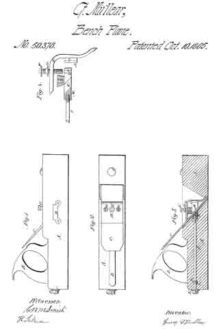
No. 1,192,849 – Bench Plane (John F. Bridges) (1916)

[paiddownloads id=”713″]1192849


UNITED STATES PATENT OFFICE.

_________________

JOHN F. BRIDGES, OF ALAMEDA, CALIFORNIA.

BENCH-PLANE.

_________________

1,192,849. Specification of Letters Patent. Patented Aug. 1, 1916.
Application filed June 15, 1914. Serial No. 845,206.

_________________

To all whom it may concern:

Be it known that I, JOHN F. BRIDGES, citizen of the United States, residing at Alameda, in the county of Alameda and State of California, have invented certain new and useful Improvements in Bench-Planes, of which the following is a specification.

My invention relates to improvements in bench planes; and as its primary object contemplates a sectional plane wherein means is provided for vertically adjusting one of the said sections relatively to the blade to in this manner vary the depth of the cut and simultaneously enlarging or diminishing the chip throat.

A further object of the invention is to provide improved and simplified means for adjusting the blade relatively to the operating surface of the plane stock.

The above and additional objects are accomplished by such means as are illustrated in their preferred embodiment in the accompanying drawings, described in the following specification and then more particularly pointed out in the claims which are appended hereto and form a part of this application.

In describing my invention in detail reference will be had to the accompanying drawings wherein like characters denote like or corresponding parts throughout the several views, and in which :–

Figure 1 is a side elevation of a bench plane constructed in accordance with the present invention; Fig. 2 is a top plan view, partly broken away; Fig. 3 is a longitudinal sectional view of the plane as shown in Fig. 2; and Fig. 4 is a cross sectional view, the back face of the blades and bed plates being shown in elevation.

Referring now to the drawings by numerals, 1 and 2 designate respectively the plane sections, the said sections forming the stock or body of the tool. A partition 3 is formed integrally with plane section 2 at its forward end, the partition having formed integrally therewith a screw block 4. Angular extensions 5 are formed integrally with the plane section 2, the said extensions 5 being formed, one at each side of the said sections, and disposed to extend inwardly as shown to advantage in Fig. 2 whereby to form vertical grooves or guide ways 6 within which angular extensions 7 integral with a partition 8 of plane section 1 is fitted, this arrangement holding the said two sections together; preventing lateral and longitudinal movement of the said two sections; yet permitting, as will hereinafter appear, vertical adjustment of plane section 1 relatively to the said section 2 for the purpose of varying the depth of the cut made by the tool.

Partition 8 is enlarged at its base as indicated at 9, the enlargement having formed therein a threaded recess 10, said recess receiving the threaded shank 11 of an operating screw designated 12, said screw having a single spirally coiled thread adapted for engagement with the groove therefor in screw block 4. An opening 14 is formed in said partition 8, said opening providing an operating space for the said screw 12.

A suitable bed plate 15 is carried by plane section 2, the said plates being disposed at an angle of approximately 45° and formed integrally with a web-like support 16 attached as indicated at 17 to lugs 18 integral with the base of section 2.

The blade 19, of the plane, is longitudinally slotted in a manner common to the art and is held in place against bed plate 15 and against an enlargement 20 of the plane base through the medium of an attaching plate 21, said plate having associated therewith a cam lever 22 pivoted as at 23 to the plate 21, the head 24 of the cam lever being adapted for frictional engagement with the top or forward face of the blade 19 to serve as a means whereby the said blade is held immovable relatively to the bed plate 15 and the fastening plate 21 in firm frictional engagement with a retaining screw 25 operating within a slot 26 of the plate 21 and extending through blade 19, said plate 15, and into an enlargement 26′ of the web-like support 16 above mentioned. The cutting edge of the blade 19 extends beneath the operating surface of the plane through an opening or transverse slot 27 formed at the forward end of plane section 2 and at the base of partition 3 thereof.

When it is desired that the depth of cut be varied to a small degree, operating screw 12 is partially rotated through manipulation of handle 28 forming a part thereof, causing plane section 1 to move vertically relatively to plane section 2, thus exposing a greater portion of the blade 19 to view. Should such adjustment prove insuflicient, and greater adjustment be desired, cam lever 22 is raised to remove attaching plate 21 out of frictional engagement with retaining screw 25 and blade 19 out of frictional engagement with bed plate 15, in which event, blade 19 is adjusted vertically as desired. When adjusted, cam lever 22 is again forced into the position shown in Fig. 3, retaining screw 25 having been previously adjusted, such forced movement of the said lever causing the attaching plate 21 to again frictionally engage the retaining screw and the blade 19 to remain immovable relatively to the said plate 15 of the plane.

A knob 29 and a handle 30 are made fast to the respective sections 1 and 2 of the plane in a manner common to the art.

From the foregoing, taken in connection with the accompanying drawings it is apparent that minute or finger adjustment is made possible by the provision of the operating screw 12; that unlimited adjustment is made possible by the cam lever 22; and that by the provision of the extensions 5 and 7, arranged as shown to advantage in Fig. 2, the sections of the plane are held against longitudinal and lateral movement independently of each other, yet, when it is desired that one of the sections be adjusted relatively to the other, such vertical adjustment is permitted.

In reduction to practice, I have found that the form of my invention, illustrated in the dravvings and referred to in the above description, as the preferred embodiment, is the most efficient and practical; yet realizing that the conditions concurrent with the adoption of my device will necessarily vary, I desire to emphasize the fact that various minor changes in details of construction, proportion and arrangement of parts may be resorted to, when required, Without sacrificing any of the advantages of my invention, as defined in the appended claims.

Having thus fully described my invention, what I claim as new and desire to secure by Letters Patent, is :–

In a bench plane; a stock section having a front wall extending at a substantially right angle to the planing surface thereof, and a frog mounted in spaced relation to said wall supporting the planing knife; in combination with a second stock section having a wall extending upwardly at right angles to the planing face thereof, and in spaced relation to the rear edge, means carried by said walls whereby said sections may be held in interlocking engagement, said second section providing a throat above the planing edge of said knife, and means to adjust said sections relatively, whereby the throat will be enlarged or constricted consistent with the variations of the depths of cut of the planing knife.

ln testimony whereof I affix my signature in presence of two witnesses.

JOHN F. BRIDGES.

Witnesses:
M. C. GORHAM,
A. W. BURGRON.

_________________

Copies of this patent may be obtained for five cents each, by addressing the “Commissioner of Patents, Washington, D. C.”
_________________

No. 1,112,399 – Bench Plane (Harvey M. Wood) (1914)

[paiddownloads id=”700″]1112399


UNITED STATES PATENT OFFICE.

_________________

HARVEY M. WOOD, OF LOS ANGELES, CALIFORNIA.

BENCH-PLANE.

_________________

1,112,399. Specification of Letters Patent. Patented Sept. 29, 1914.
Original application filed November 8, 1907. Serial No. 401,341. Divided and this application filed October
14, 1912. Serial No. 725,577.

_________________

To all whom it may concern:

Be it known that I, HARVEY M. WOOD, a citizen of the United States, residing at Los Angeles, in the county of Los Angeles and State of California, have invented a new and useful Bench-Plane, of which the following is a specification.

The object of this invention is to protect the cutting edge of the blade during the backward stroke of the plane and while standing idle on its sole, this result being attained by use of a heel-piece yieldingly projecting through and beyond the sole and serving to normally uphold the same above the table top.

This application is a division of my co-pending application for patent on bench plane, Serial No. 401,341, filed Nov. 8, 1907.

The accompanying drawings illustrate the invention.

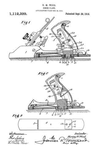
Figure 1 is a side elevation partly in mid-section, showing the details of the heel-piece and the symmetrical mechanism for operating the same. Fig. 2 is a similar view showing a modification of the mechanism for operating the heel-piece. Fig. 3 is a reduced plan of the bottom of either of the planes shown in Figs. 1 and 2.

Numeral 1 refers to the shoe of an ordinary plane having a blade 2, hollow handle 3, sole 4, and yieldingly extended retractible heel-piece 5, the latter projecting normally through aperture 6 and extending substantially across the sole. A spring 8, fixed to the shoe and engaging notch 9 in the heel-piece normally projects the heel-piece through the sole so that when the plane rests loosely upon the work or on the bench top 7, or is being drawn backward over the same, the heel and the cutting edge will be raised off the work as shown in the drawings, thus saving the cutting edge from all unnecessary contact and preserving its keenness. On the forward or planing stroke, however, it is essential that the cutting edge come onto the work immediately and manually operated means are provided whereby the forward pressure of the workman’s hand in the operation of planing, will automatically retract the heel-piece. With this object in view, there is provided a rear handle section or palm piece 10, suitably connected with the heel-piece to retract it into the shoe and permit the sole and cutting edge to come down onto the work. The heel-piece 5 may be unitarily constructed with, or may be attached by screws 13 to a carrier block 14 having uprights 15 and vertically movable in the shoe; the uprights being provided with vertical slots 17 running on a pintle 18 rigidly mounted in the handle and thus assisting in guiding the carrier and heel-piece.

In the form shown in Fig. 1, linkage is provided for retracting the heel-piece. The link 22 is pivotally mounted at one end on the palm piece 10 and is pivotally connected at the other end by pin 23 to a bell-crank 24 that is pivotally supported on the handle by means of the pivot 25, and that is provided at its operating end with a forked arm 26, the prongs of which cooperate with pin 27 to retract the heel-piece and carrier. By this means the heel-piece will be automatically retracted in an obvious manner by the forward pressure of the workman’s hand on the palm piece during the cutting stroke.

In the form shown in Fig. 2, the palm piece 10 carries a downwardly and forwardly inclined cam member 12, adjacent which the uprights are provided with a revolubly mounted cam follower 16 adapted to cooperate with the cam member 12 to raise the carrier block and heel-piece when the palm piece 10 is pressed forward. A latch comprising a finger piece 19 and stop 20 is provided to engage a notch 21 of the heel-piece to hold the heel-piece retracted with its face flush with the sole. When the heel-piece is latched, the plane operates like an ordinary plane during both the forward and return strokes.

I claim :–

1. In a plane the combination of a shoe, a blade, a handle behind said blade, said handle being rigidly mounted on said shoe, and said handle having a rear member movably mounted, a heel-piece arranged to normally project beyond the shoe, and means connecting the said rear member of the handle with the heel-piece and adapted to retract the said heel-piece when the rear section of the handle is moved.

2. In a plane the combination of a shoe, a blade, a spring operated heel-piece arranged to normally project beyond the shoe, a handle behind said blade, said handle being rigidly mounted on said shoe, and said handle having a movably mounted rear section, means connecting the said rear section of the handle with the heel-piece and adapted to retract the said heel-piece when the rear section of the handle is moved, and means for holding said heel-piece in its retracted position.

3. In a plane, the combination of a shoe, a blade, a hollow handle having a rear section pivotally mounted, a spring-operated heel-piece adapted to normally project beyond the shoe and mechanism in the hollow of the handle connecting the rear section of the handle with the heel-piece and adapted to retract the heelfpiece when the rear sec-
tion of the handle is moved.

4. In a plane the combination of a shoe, a blade, a hollow handle having a rear section pivotally mounted, a spring operated heel-piece adapted to normally project beyond the shoe, and link mechanism supported in the hollow of the handle and connecting the rear section of the handle with the heel-piece and adapted to retract the heel-piece when the rear section of the handle is moved.

5. In a plane the combination of a shoe, a blade, a hollow handle having a rear section pivotally mounted, a carrier riding in the hollow of the handle, a heel-piece mounted on the carrier and adapted to normally project through and beyond the shoe, and means in the hollow of the handle connecting the rear section of the handle with the carrier and adapted to retract the carrier and heel-piece by motion of the rear section of the handle.

6. In a plane the combination of a shoe, having a sole, a blade, a hollow handle having a rear section pivotally mounted, a heel-piece adapted to normally project beyond the sole, a bell-crank mounted within the handle and having a forked arm, a link connecting one arm of the bell-crank with the rear section of the handle, and a pin mounted on the heel-piece and cooperating with the forked arm of the bell-crank to be raised by the same.

7. In a plane, the combination with a shoe, a blade and a handle behind said blade, of a spring-operated heel-piece carried by said handle and arranged to lift the heel of the plane, and manually operated means for retracting said heel-piece.

8. In a plane, the combination with a shoe, a blade and a handle behind said blade, of a spring-operated heel-piece carried by said handle and arranged to lift the heel of the plane, means for retracting said heel-piece, and means for holding said heel-piece in its retracted position.

9. A plane comprising a sole, a handle fixed to said sole and provided with a movable palm-piece, and a heel piece operatably connected to the palm-piece and normally below the plane of the sole and adapted to be raised by movement of said palm-piece.

In testimony whereof, I have hereunto set my hand at Los Angeles, California, this 28th day of September 1912.

HARVEY M. WOOD.

In presence of —
JAMES R. TOWNSEND,
ROBERT A. STEPS.

_________________

Copies of this patent may be obtained for five cents each, by addressing the “Commissioner of Patents, Washington, D. C.”
_________________

No. 913,959 – Scraper (Noble Keller) (1909)

[paiddownloads id=”658″]913959


UNITED STATES PATENT OFFICE.

_________________
NOBLE KELLER, OF LOS ANGELES, CALIFORNIA.

SCRAPER.

_________________
913,959. Specification of Letters Patent. Patented March 2, 1909.
Application filed January 10, 1908. Serial No. 410,191.

_________________
To all whom it may concern:

Be it known that I, NOBLE KELLER, a citizen of the United States of America, residing at Los Angeles, in the county of Los Angeles, State of California, have invented a certain new and useful Scraper; and l do hereby declare the following to be a full, clear, and exact description of the invention, such as will enable others skilled in the art to which it appertains to make and use the same.

This invention relates to a scraper and has among other objects, to provide a tool of this description, of simple and cheap construction which shall be efficient and durable in use and wherein the cutting blade can be readily formed, without the use of tools, other than those usually possessed by the user of the device.

It is also an object to provide a scraper that can be worked close up to any projection perpendicular to the surface on which it is used.

Another object is to provide means for easily adjusting the scraper blade.

A further object is to provide a scraper of such form that it can be readily grasped and pressure applied thereto without fatiguing the hands of the operator.

Still another object is to provide a scraper in which the blade need not be removed to sharpen the same.

One form in which this invention may be embodied, is herein described and is illustrated in the accompanying sheet of drawings, in which —

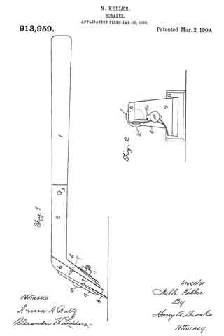
Figure 1 is a side elevation, and Fig. 2 is a rear elevation with portions broken away.

A handle 1 is fitted into a tubular socket 2, being retained therein by a pin or rivet 3. The rearward end of socket 2 has a downwardly deflected flattened portion 4, to which is attached by screws 5, a bolster 6, prefer-
ably formed of wood or other slightly yielding material. The lower portion of bolster 6 has a rabbet 7, which receives the upper portion of a blade 8, said blade being held frictionally between bolster 6 and a back plate 9, by means of bolt 10, which passes through a slot 9a in back plate 9, bolster 6, and downwardly deflected portion 4 of the handle, and has on its forward end, a nut 11. The sides of blade 8 may be beveled and sharpened in the same manner as the bottom of said blade. Blade 8 is preferably wider than back plate 9 and bolster 6. It may be formed of any convenient piece of sheet metal, such as an old saw blade, and there being no holes through it, it can readily be made with such tools as are usually carried by a wood worker.

The mode of operation of this invention is as follows: Handle 1 is grasped by one hand of the operator, while the other hand rests upon the top of bolster 6 and back plate 9. These parts being designed as shown, the hand rests easily upon this portion of the assembled tool and pressure may be applied without great fatigue to the operator.

The scraper is used by drawing it along the surface to be scraped, in the usual manner, as will be readily understood by those skilled in the art to which this invention appertains. In working close to vertical surfaces, the scraper may be laid upon its side and the ends of the blade used. In such use of the device, it will be readily understood that the handle extends away from the vertical surface, so that there is a sufficient clearance to enable the operator to manipulate the device conveniently. The blade 8 may be protruded, as it becomes worn, by striking on the upper sides of the projecting portions.

I claim:

1. A scraper comprising ahandle having a widened portion at the lower end thereof, a wooden bolster affixed to said portion, a back plate, said bolster and said plate suitably shaped to afford a hand-rest thereon when the same are assembled, a single bolt having a nut threaded thereon and passing through said plate, bolster, and widened portion of the handle, whereby the blade may be clamped between said bolster and said back plate.

2. A scraper comprising a handle, a metal tube affording a socket for said handle and having a flattened part bent at an angle to said socket, a wooden holster secured to said flattened part, said bolster shaped to afford a hand-rest thereon, and having a out-away portion to accommodate a blade, a slotted back plate, a single bolt having a nut threaded thereon and passing through said plate, bolster, and flattened part, whereby the blade may be clamped between the bolster and the back plate.

In testimony whereof, I have signed my name to this specification in the presence of two subscribing witnesses at Los Angeles county of Los Angeles, State of California this 31st day of December A. D., 1907.

NOBLE KELLER.

Witnesses:
ALEXANDER H. LIDDERS,
ANNA A. BALTZ.

No. 840,418 – Carpenter’s Plane (William F. Arnold) (1907)

[paiddownloads id=”637″]840418


UNITED STATES PATENT OFFICE.

_________________
WILLIAM F. ARNOLD, OF OAKLAND, CALIFORNIA.

CARPENTER’S PLANE.

_________________
840,418. Specification of Letters Patent. Patented Jan. 1, 1907.
Application filed September 12, 1906. Serial No. 334,372.

_________________
To all whom it may concern:

Be it known that I, WILLIAM F. ARNOLD, a citizen of the United States, residing at Oakland, in the county of Alameda and State of California, have invented certain new and useful Improvements in Carpenters’ Planes, of which the following is a specification.

My invention relates to the class of carpenters’ planes, and is applicable to smoothers, jointers, or jack-planes.

The objects of my invention are to provide a better bearing in the stock for the shoe, to avoid cutting too much of the stock away to let the shoe in, to provide an accurate adjustment for the cutting-bit without friction or lost motion, and to provide an effective and easily-operated means for clamping the cutting-bit to the shoe.

To these ends my invention consists in the novel constructions and combinations, which I shall hereinafter fully describe by reference to the accompanying drawings, in which —

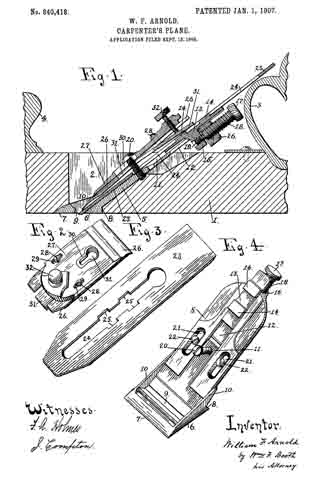
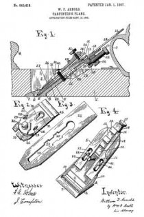
Figure 1 is a longitudinal vertical section of a plane embodying my improvements. Fig. 2 is a perspective view of the top bit. Fig. 3 is a perspective view of the cutting-bit. Fig. 4 is a plerspective view of the shoe.

1 is the stock, aving the throat 2, handle 3, and button 4.

5 is the shoe. Its lower end, or, as it may be termed, its “sole” 6, is flat, with a beveled toe 7 and a shouldered heel 8. Through the sole is made the bit-opening 9. The sides of the sole are bounded by low flanges 10.

In the shank of the shoe is formed a groove 11, which near its upper portion is out through to form a slot 12. In the groove 11 is seated a slide 13, on the upper surface of which is a bit-holding lug 14. This lug may be of any shape, here shown rectangular, and there may be more than one of them, two being here shown. From the under side of the slide projects a lug 15, which plays in the slot 12 of the shoe-shank. The end of said shank is formed with a downwardly-projecting lug 16. An adjusting-screw 17 is seated in lugs 16 and 15, said screw having, as shown in Fig. 1, its outer portion 18, which passes through lug 16, right-hand threaded and its inner portion 19 reduced and left-hand threaded to opperate in lug 15. By this reversal of the threads the screw 17 is enabled to move the slide 13 up or down.

The shoe 5 has a central binding-screw 20, and on each side it has slots 21, in which are fitted holding-screws 22. The shoe 5 is fitted to the stock 1 by passing it up through the throat 2 from below, so that, as seen in Fig. 1, its sole 6 fits up flush with the bottom of the stock, the throat being correspondingly cut away to receive said sole. At this point two improvements are to be noted. The first is that by having the shouldered heel 8 fitting squarely, as seen in Fig. 1, against a substantial thickness of the stock the latter at this point is not, as is usual, cut down to a feather-edge, which is a defect, both in affording a weak bearing and in permitting the entrance of slivers; but with the substantial heel 8, bearing against a good thickness of wood, afirm bearing is obtained against end thrust, and no splinters can enter. The second point is that by having the low side flanges 10 on the sole of the shoe I need cut away but a small portion of the throat-walls to receive them flush.

In the ordinary construction in which the side flanges of the shoe run up high to receive the cross-pin which forms part of the bit-holding devices a great part of the throat-walls has to be cut away to let them in. This weakens the stock across the throat, and many stocks break in falling; but with the low flanges 10 of my construction a minimum of wood is cut away to fit them, and said flanges can be low, because I dispense with the customary cross-pin which they usually carry.

The shoe 5 is adjustably secured to the stock by the holding-screws 22, (seen in Fig. 4,) which are deep-seated in the wood. The binding-screw 20 also enters the wood, as seen in Fig. 1.

23 is the cutting-bit. It is formed with a long slot 24, provided with enlargements 25. The cutting-bit lies upon the shoe 5, its slot 24 fitting over the binding-screw 20 and its enlargements 25 fitting over the holding-lugs 14 of the slide 13.

The top bit shown in Fig. 2 is composed, as usual, of the blank blind bit 26 and the top cap 27. The two are adjustably fitted together by the screws 23, passing through the slots 29. A slot 30 in the top cap and an alined slot 31 in the blind bit, Fig. 1, enable them to be fitted over the binding-screw 20.

The novel feature of the to bit is the slitting of the blind bit 26 to form a spring-tongue 31, Fig. 2. Against this spring-tongue bears a pressure-screw 32, seated in the top cap, which has the function when the top bit is in place, as shown in Fig. 1, of forcing the spring-tongue down upon the cutting-bit, which pressure being resisted by the binding-screw 20 effectually clamps both top bit and cutting-bit to the shoe. By relieving this pressure, as by turning back the pressure-screw 32, the cutting-bit can be properly adjusted through the action of the adjusting-screw 17. The shoe itself can be adjusted as the stock wears, and the top bit can be adjusted on the cutting-bit to determine the shaving.

The advantage of the right and left threaded adjusting-screw 17 is that its threaded bearing in the slide-lug 15 is less liable to friction and to wear and tear resulting in lost motion than if a plain collar-bearing were used, as is customary. It is accurate and easy in its movement.

Another advantage of my invention lies in the connections between the cutting-bit and the adjacent parts which result in freeing said bit of all directly-connected lugs or other attachments which tend to interfere with the work of sharpening it. As I have it there is nothing connected with it and it is left clean to be handled as required.

Having thus described my invention, what I claim as new, and desire to secure by Letters Patent, is —

1. In a carpenter’ s plane, a shoe having its sole formed with a shouldered heel to bear against a corresponding shoulder in the stock-throat.

2. In a carpenter s plane, the combination of a stock, the throat of which at the lower terminus of its rear wall is formed with a bearing-shoulder, and a shoe the sole of which is formed with a shouldered heel bearing against the shoulder of the stock-throat.

3. In a carpenter’s plane, the combination of a shoe secured in the stock-throat, the shank of said shoe having a groove terminating in a slot at its upper end; a slide seated in said shoe-shank groove, and having a lug passing down through said slot said slide having also a holding-lug on its upper surface; a cutting-bit having an opening to engage the holding-lug of the slide; means for clamping the bit to the shoe ; and means engaging the downwardly-extending lug of the slide for adjusting said slide.

4. In a carpenter’s plane, the combination of a shoe secured in the stock-throat, the shank of said shoe having a groove terminating in a slot at its upper end; a slide seated in said shoe-shank groove and having a holding-lug on its upper surface; a cutting-bit having an opening to engage the holding-lug, means for clamping the bit to the shoe; and means for adjusting the bit consisting of a lug on the slide playing down through the shoe-shank slot, a lug on the shoe, and a right and left hand threaded screw seated in said lugs.

5. In a carpenter’s plane, the combination of a shoe secured in the stock-throat, the shank of said shoe having a groove terminating in a slot at its upper end; a slide seated in said shoe-shank groove; a cutting-bit; inter-engaging devices between the bit and slide; means for clamping the bit to the shoe; and means for adjusting the bit consisting of a lug on the slide playing down through the shoe-shank slot, a lug on the shoe, and a right and left hand threaded screw seated in said lugs.

6. In a carpenter’s plane, the combination of a shoe secured in the stock-throat; a cutting-bit adjustably seated on the shoe; a top bit comprising a blank blind bit and a top cap, said blind bit being slit to form a spring-tongue; a pressure-screw in the top cap to force the spring-tongue down upon the cutting-bit; and a binding-screw passing through the top bit, the cutting-bit and the shoe, into the stock, to resist the pressure-screw, whereby the cutting-bit is clamped to the shoe.

7. In a carpenter’s plane, the combination of a shoe secured in the stock-throat; a slide seated in the shoe and having a holding-lug on its face; means for adjusting the slide; a cutting-bit having an opening engaging the holding-lug of the slide; a top bit comprising a blank blind bit and a top cap, said blind bit being slit to form a spring-tongue; a pressure-screw in the top cap to force the spring-tongue down upon the cutting-bit; and a binding-screw passing through the top bit, the cutting-bit and the shoe, into the stock, to resist the pressure-screw, whereby the cutting-bit is clamped to the shoe.

8. In a carpenter’s plane, the combination of a shoe secured in the stock-throat; a slide seated in the shoe and having a holding-lug on its face; means for adjusting the slide consisting of a lug on the slide, a lug on the shoe and a right and left hand threaded screw engaging said lugs; a cutting-bit having an opening engaging the holding-lug of the slide; a top bit comprising a blank blind bit and a top cap, said blind bit having a spring-tongue; a pressure-screw in the top cap to force the spring-tongue down upon the cutting-bit; and a binding-screw passing through the top bit, the cutting-bit and the shoe, into the stock, to resist the ressure-screw, whereby the cutting-bit is clamped to the shoe.

9. In a carpenter’s plane, the combination of a shoe having its solle formed with a shouldered heel and bounded by low side flanges, said sole being iet into corresponding depressions in the stock, a slide seated in the shoe and having a holding-lug on its face; means for adjusting the slide, consisting of a lug on the slide, a lug on the shoe and a right and left hand threaded screw engaging said lugs; a cutting-bit having an opening engaging the holding-lug of the slide; a top bit comprising a blank blind bit and a top cap, said blind bit having a spring-tongue; a pressure-screw in the top cap to force the spring-tongue down upon the cutting-bit; and a binding-screw passing through the top bit, the cutting-bit and the shoe, into the stock, to resist -the pressure-screw, whereby the cutting-bit is clamped to the shoe.

In testimony whereof I have signed my name to this specification in the presence of two subscribing witnesses.

WILLIAM F. ARNOLD.

Witnesses:
CHARLES H. TAYLOR,
N. A. ACKER.

No. 799,234 – Carpenter’s Plane (John Jett) (1905)

[paiddownloads id=”624″]799234


UNITED STATES PATENT OFFICE.

_________________
JOHN JETT, OF SAN FRANCISCO, CALIFORNIA.

CARPENTER’S PLANE

_________________
799,234. Specification of Letters Patent. Patented Sept. 12, 1905.
Application filed August 18, 1904. Serial No. 221,296.

_________________
To all whom it may concern:

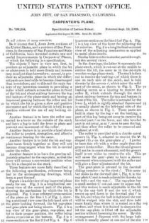
Be it known that I, JOHN JETT, a citizen of the United States, and a resident of San Francisco, in the county of San Francisco and State of California, have invented certain new and useful Improvements in Carpenters’ Planes, of which the following is a specification.

The objects I have in view are, first, to produce an adjustable plane in which the bit or plane-iron is held more firmly and is more easy to adjust than heretofore; second, to produce an adjustable plane in which the different parts are less liable to become disarranged than heretofore; and to this end the main feature of my invention consists in providing a roller which extends across the plane in front of the bit and about midway between the top and bottom of the plane-stock and having an improved gearing between the roller and bit by which the bit is given a slow and positive movement and by which the bit is held in any position without the use of any locking device.

Another feature is to have the roller connected to a lever on the outside of the stock and have a lug to hold the lever in place and prevent end movement of the roller.

Another feature is to provide a hood above the roller to protect, strengthen, and afford a continuous bearing for the same.

Another feature is to hold the bit and cap-plate more firmly together so they will not become disarranged when the bit is carried under the roller.

Another feature is to have the gearing adjustably attached to the cap-plate, so that the lever will occupy a convenient position when the bit is clamped to the stock.

These features are more fully described in the following specification, reference being had to the accompanying drawings, which form a part thereof.

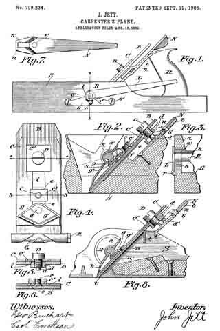
Figure 1 is a side view of my improved plane ready for use. Fig. 9. is a longitudinal sectional view of the central part of the plane, showing the mechanism by which the bit is adjusted. Fig. 3 is an enlarged cross-section of the plane on the line 1 1 of Fig. 1, showing a sectional view near the left-hand side of the plane looking forward, the bit cap-plate and gear-plate not being shown. Fig. A is a top view of the gear-plate, cap-plate, and bit in their proper position, the roller being shown crosswise at the bottom. Fig. 5 is a cross-section on the line 2 2. of Fig. 4. Fig. 6 is a cross-section on the line 3 3 of Fig. 4. Fig. 7 is a top view of the lever for adjusting the bit sidewise. Fig. 8 is a longitudinal sectional view of the adjusting mechanism as applied to metal plane-stocks.

Similar letters refer to similar parts throughout the several views.

In the drawings, the letter S represents the plane-stock, which is cutout at the middle to receive the bit, the same as in the old-style wooden-wedge plane-stock. The stock is then cut to receive the bushing x, of which there is one on each side of the stock, and is held thereto by the screws x’, which enter the solid part of the stock, as shown in Fig. 2. The bushing serves as a bearing to receive the roller R, which extends through the stock about midway between the top and bottom in front of the bit. The roller is actuated by the lever L, which is rigidly attached thereto and is usually placed on the left-hand side of the plane, as shown in Fig. 1. These parts are held in place by the lug r on the bushing, a part of this lug being cut away to receive the beveled part l on the lever, and this beveled part is cutaway, as at l’, so as to pass the lug, and thus allow the roller to be removed and replaced at will.

The roller is provided with a double spiral groove G, Fig. 4, adapted to receive the V-shaped rib g on the gear»plate g’ I prefer to have this rib with a wider angle than the groove in the roller. Then the rib and groove will not be in exact alinement, and the groove itself is cut wider to receive the rib. This will cause the gear-plate to have a slower movement when compared with the roller and will give a finer adjustment of the bit.

The gear-plate is pivoted to the dovetail sliding member e bythe rivet e’. This member slides in the dovetail slot i, Fig. 6, in the cap-plate C and is made adjustable thereto by the bolt c and the nut c’. The cap-plate has a small section C’ cut out near its upper end, and this section is made adjustable to the bit B by the cap-bolt D and the nut d, which moves up and down in the dovetail slot i’ in the bit, and when the bolt is tightened the nut will be wedged into the slot, and thus held more firmly than where it is seated on a flat surface, and when it is desired to sharpen the bit the cap-plate is lifted off the adjustable section without loosening the screw. By this arrangement I dispense with the large hole which is usually placed at one end of the slot in the bit. I therefore make the slot of uniform width, which requires less work and less material.

Above the roller is the hood lt, which serves to protect the gearing and strengthen the roller and gives it a bearing the entire distance between the bushings. It extends from side to side on the inside of the plane, and its cross-section, as shown in Fig. 2, is uniform from side to side. It extends under the abutment a at each side of the plane, as shown in Fig. 3, and I prefer to have the semisleeve a’ on the bushing extend out flush with the abutment, as shown in Figs. 2 and 3, as this connects the hood firmly to the bushings; but this can be dispensed with, if desired. The abutment serves to hold the upper part of the hood firmly down on the roller and the lower part firmly down on the cap-plate, and when the roller is removed the hood is easily taken out.

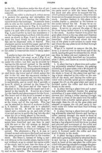
I prefer to have the bed, or “that part just behind the bit,” cut away, as at f, Fig. 2, so as to allow the bit to spring when it is carried under the roller; but this can be avoided by having the bit curved upward in the middle when out of the plane. Then when it is carried under the roller it will spring almost straight.

The bit can be adjusted sidewise by a pivoted lever, the lower end of which enters the slot in the bit near the cap-screw similar to the ones now in general use; but this requires a long slot, and consequently a long bit, which is undesirable, and to avoid this I provide a lever N, which is pivoted to the brace b by the rivet b’. The lower end of this brace is attached to the stock and the upper end is attached to the handle H. It serves as a brace for the handle and also a support for the lever. The lower end of this lever is pressed or bent upward, as at n, and this part is provided with a slot n’, adapted to receive the lug d’ at the lower end of the cap-bolt. This lug can be attached to the nut d, as shown in Fig. 8, if desired. In either case it is attached firmly to the bit. It will be seen that the raised part n, extends up on each side of the rivet and serves to guide the lug into the slot when the bit is being placed in the stock.

It will also be seen that the old style wooden-wedge plane can be converted to use the mechanism here described and can then be used with the new or the old system, as desired. My improvement is also well adapted for metal plane-stocks, in which no bushing is required. The abutment a, Fig. 8, is cast or riveted on each side above the hood and serves the same purpose as described in the wooden stock. The brace b, instead of being a narrow strip as in the wooden plane, has its lower end widened, so as to extend the entire width of the stock, and is bent into the form of an angle. The vertical part t passes through a slot in the upper edge of the stock and is riveted on the outside. The horizontal part t’ rests on the upper edge of the stock. These two parts serve to hold the brace firmly to the stock and also serve to support the bit, which presses strongly thereon; otherwise the brace serves the same purpose as in the wooden stock. Another feature in this plane is the wooden fender w, attached to the bottom on the inside behind the bit. It may be an extension of the handle or may be a separate piece. It serves to prevent the edge of the bit from being dulled when it is being placed in the stock. Another feature is to pivot the gear-plate direct to the cap-plate and dispense with the dovetail sliding member previously described. This works well where the bottom of the plane is not subject to much wear and where the cap-plate is not shifted through a wide range.

When it is desired to remove the bit, the lever L is moved over to the front end of the stock, causing the gear to release the bit, which can then be taken out and replaced at will.

Having thus fully described my invention, what I claim, and desire to secure by Letters Patent, is —

1. A plane having a plane-iron and a gearing adjustably attached thereto, the gearing consisting of a gear-plate with a V-shaped rib thereon, and having a roller passing through the stock in front of the plane-iron and having a lever attached to the roller on the outside of the stock, and having the roller provided with a double spiral groove adapted to engage the rib on the gear-plate and carry it forward under the roller and thus bind it firmly to the stock.

2. A plane having a plane-iron and a gearing adjustably attached thereto the gearing consisting of a gear-plate with a V-shaped rib thereon and having a roller passing through the stock in front of the plane-iron the roller provided with a double spiral groove with a less angle than the rib on the gear-plate and adapted to engage the rib and carry it forward under the roller and thus bind it firmly to the stock.

3. A plane having a plane-iron and a gearing adjustably attached thereto and having a roller passing through the stock in front of the plane-iron, and having a lever attached to the roller on the outside of the stock and having a lug adapted to hold the lever in place and prevent end movement of the roller and having the roller provided with gearing adapted to engage the gearing on the plane-iron and carry it forward under the roller and thus bind it firmly to the stock.

4. A plane having a plane-iron and a cap-plate and a gearing adjustably attached thereto and having a roller passing through the stock in front of the cap-plate the roller provided with gearing adapted to engage the gearing on the cap-plate and carry it forward under the roller and thus bind it firmly to the stock.

5. A plane having a plane-iron and a cap-plate with a small section cut out near its upper end and having the section adjustably attached to the plane-iron by a bolt and nut the nut being adapted to wedge into the slot of the plane-iron and having a gearing adjustably attached to the cap-plate and having a roller passing through the stock in front of the cap-plate the roller provided with gearing adapted to engage the gearing on the cap-plate and carry it forward under the roller and thus bind it firmly to the stock.

6. A plane having a plane-iron and a gearing adjustably attached thereto and having a roller passing through the stock in front of the plane-iron and having a hood above the roller on the inside of the stock adapted to strengthen the roller and afford a good bearing for the same, the roller provided with a gearing adapted to engage the gearing on the plane-iron and carry it forward under the roller and thus bind it firmly to the stock.

JOHN JETT.

Witnesses:
J. M. EVERS,
S. THORN.

No. 761,097 – Router-Plane (McCluer H. Parker) (1904)

[paiddownloads id=”603″]761097


UNITED STATES PATENT OFFICE.

_________________
McCLUER H. PARKER, OF LOS ANGELES, CALIFORNIA.

ROUTER-PLANE.

_________________

SPECIFICATION forming part of Letters Patent No. 761,097, dated May 31, 1904.
Application filed December 15, 1903. Serial No. 185,228. (No model.)

_________________
To all whom it may concern:

Be it known that I, McCLUER H. PARKER, a citizen of the United States, residing at Los Angeles, in the county of Los Angeles and State of California, have invented a new and useful Router-Plane, of which the following is a specification.

This invention relates to improvements in router-planes, and particularly to the adjusting and clamping of the cutting knife or bit.

The router-plane forming the present invention is particularly adapted for routing out seats for door butts or hinges and for cutting out for locks and strike-plates for the same. The plane is of value in cutting seats for other building hardware or material that requires inlaying.

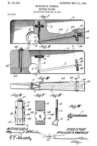
The accompanying drawings illustrate the invention, and referring to the same, Figure I is a side view of the router-plane with part of the stock broken away, showing the preferred construction. Fig. II is a side view of the router-plane, with part of the stock broken away, of another form. Fig. III is a bottom view of the form shown in Fig. I. Fig. IV is a view looking toward the nose of the form shown in Fig. II. Fig. V is a section on line V V, Fig. II. Fig. VI is a detail in perspective of the cutter or bit. Fig. VII isa detail in perspective of the clamping-rod.

1 designates the stock, which preferably tapers throughout its length, as shown, being wider at the heel than at the nose.

2 designates the cutting iron or bit, which is provided with a squared shank 3, the upper end of which is threaded, as at 4. The squared shank 3 is received by the stock of the plane in a square hole, and when in position the flat faces of the shank engage the flat faces of the hole to hold the shank from rotation relatively to the stock, the hole extending substantially at right angles to the bottom of the stock, and the cutting-iron 2 projects slightly downward and forward from the rear part of the throat 5 of the stock.

6 is a knurled thumb-nut which is mounted on the threaded shank 3, the stock 1 being slotted to receive the thumb-nut 6, and the edges of the nut protrude, as shown in Fig. III, so as to be readily grasped by the fingers in adjusting the cutting-iron.

7 is a clamping-bar having an eye 8, which is squared internally to receive the shank 3 of the cutting-iron, the shank 3 loosely fitting in the eye. The other end of the clamping-bar 7 is threaded, as at 9. and carries a locking-nut 10, the periphery of which is provided with square notches 11, which afford shoulders against which a tool may be struck-such, for instance, as a nail-set-to tighten the clamping-nut securely.

The stock 1 is slotted to receive the clamping-nut 10, and a washer 12 is provided within the stock 1, against which the locking-nut bears when screwed tight.

As shown, the clamping-bar extends from the rear of the throat 5 nearly to the heel of the plane and is inclined so as to bring the clamping-nut well above the bearing-face or bottom of the stock.

In the preferred form the stock 1 is made of a single piece of wood, and in order to put the clamping-bar in place in the stock the stock is drilled from the heel toward the throat with a hole of sufflcient diameter to allow of the passage through it of the eye 8, and a wooden sleeve 13, which is drilled centrally to receive the locking-bar 7, together with the locking-bar 7, is slipped into the hole in the stock from the heel, the sleeve before being inserted having had glue applied to its surface and the hole in the stock also having had glue applied to its surface, so that when the sleeve is in place in the stock the glue sets and the sleeve becomes practically part of the stock. A plug 14 is then glued into the stock to fill the end of the hole. Another form is shown in Fig. II, in which the lower part of the nose 15 is fastened to the upper part 16 by a tongue-and-groove joint, a tightening-screw 17 passing down through a wide slot 18 in the stock and screwing into the adjustable part 15. When the plane is of metal, it may preferably be constructed in this form and the sleeve 13 may be dispensed with, as the adjustable nose 15 may be moved forward or entirely removed from the stock to permit the locking-bar 7 to be slipped into place in the stock from the front, the hole in the stock in such cases being drilled of a size to just receive the shank of the locking-bar. After the locking-bar is in place the nose 15 may be fastened by tightening the screw 17.

When the lock-nut 10 is screwed up tight, it draws the locking-bar 7 to the rear and forces the shank 3 tightly against its squared seat in the stock 1, and the cutting-iron 2 is thus prevented from turning sidewise or from slipping up or down. To adjust the cutting-iron 2, the lock-nut 10 is loosened, which frees the shank 3, so that the nut 6 may be readily turned by the fingers to raise or lower the cutting-iron 2, and when it has been brought to the desired position the lock-nut 10 is again tightened, being easily forced very tightly into place by inserting a nail-set in a notch of the lock-nut and tapping the same.

I have found in practice that a plane constructed as herein set forth more than doubles the capacity of a mechanic in hinging doors and in doing other similar work and that the grade of work is also improved to a marked degree.

What I claim is —

1. A stock having a throat and having a hole extending substantially at right angles to the bottom of the stock, a cutting-iron having a shank lying in said hole, the shank and the part of the stock engaging therewith being formed with engaging parts to hold the shank from rotation, the shank having a threaded portion and a nut on the threaded portion for adjusting the cutting-iron, and means for clamping the shank.

2. A stock having a throat, and having a hole with a fiat face extending at substantially right angles to the bottom of the stock, a cutting-iron having a shank with a flat face lying in the hole, the shank having a threaded portion, and a nut on the threaded portion for adjusting the cutting-iron, and means for clamping the shank.

3. A stock having a throat, and having a hole with a flat face extending substantially at right angles to the bottom of the stock, a cutting-iron having a shank with a flat face lying in the hole, the shank having a threaded portion, a nut on the threaded portion for adjusting the cutting-iron, means for clamping the shank, and a clamping-bar having an eye through which the shank passes, the clamping-bar having a threaded portion, and a nut on the threaded portion for tightening the clamping-bar.

4. A stock, a cutting-iron having a squared shank threaded at one end, the shank lying within a square hole in the stock and substantially perpendicular to the bottom of the stock, a nut on the threaded portion of the shank within a slot in the stock, a clamping-bar having a squared eye which receives the shank of the cutting-iron, the clamping-bar having a threaded portion, and a nut on the threaded portion in a slot in the stock.

5. A stock, a cutting-iron having a squared shank threaded at one end, the shank lying within a square hole in the stock and substantially perpendicular to the bottom of the stock, a nut on the threaded portion of the shank within a slot in the stock, a clamping-bar having a squared eye which receives the shank of the cutting-iron, the clamping-bar having a threaded portion, and a nut on the threaded portion in a slot in the stock, said latter nut having a notched periphery.

6. A stock, a cutting-iron having a squared shank threaded at one end, the shank lying within a square hole in the stock and substantially perpendicular to the bottom of the stock, a nut on the threaded portion of the shank within a slot in the stock, a clamping-bar having a squared eye which receives the shank of the cutting-iron, the clamping-bar having a threaded portion, a nut on the threaded portion in a slot in the stock, said latter nut having a notched periphery, and a washer between the stock and the forward face of the latter nut.

In testimony whereof I have hereunto signed my name, in the presence of two subscribing witnesses, at Los Angeles, in the county of Los Angeles and State of California, this 7th day of December, 1903.

McCLUER H. PARKER.

Witnesses:
GEORGE T. HACKLEY,
JULIA TOWNSEND.

No. 755,587 – Scraping-Plane (William Ulses) (1904)

[paiddownloads id=”600″]755587


UNITED STATES PATENT OFFICE.

_________________

WILLIAM ULSES, OF LOS ANGELES, CALIFORNIA.

SCRAPlNG-PLANE.

_________________
SPECIFICATION forming part of Letters Patent No. 744,587, dated March 22, 1904.
Application filed October 29, 1903. Serial No. 179,070. (No model.)

_________________

To all whom it may concern:

Be it known that I, WILLIAM ULSES, a citizen of the United States, residing at Los Angeles, in the county of Los Angeles and State of California, have invented new and useful Improvements in Scraping-Planes, of which the following is a specification.

My invention relates to a plane for finishing surfaces made nearly smooth by the ordinary cutting-planes; and the object thereof is to provide a tool by means of which planed surfaces may be readily finished and with less danger of roughing the surface than if an ordinary scraper were used.

I accomplish this object by the scraping-planes described herein and illustrated in the accompanying drawings, in which —

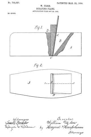
Figure 1 is a side elevation, with a portion in longitudinal central section taken on the line 1 1 of Fig. 2, of my scraping-plane. Fig. 2 is a view of the sole of my plane.

In the drawings, A is the stock, having a throat B for the reception of the plane-iron C and the binding-wedge D, which secures the plane-iron in the throat, binding it against abutments A’ on the sides of the throat. These abutments are shown in dotted lines in Fig. 1, the inner dotted line representing the top line of the abutments and the outer line representing the bottom line of the abutments. The tops of these abutments project forwardly of the bottoms, so that the top of the plane-iron is inclined forwardly, as shown in Fig. 1, when the wedge and iron are in place. I have found by practical test that an inclination of five-sixteenths of an inch in a stock of two inches in height produces very satisfactory results. The plane-iron is constructed, preferably, of a thin piece of tempered steel having the lower edges C’ thereof sharpened, as shown in Fig. 1, or otherwise formed into a scraping-surface. The front side of the binding-wedge forms the segment of a circle, and when the scraper-iron is secured in the stock it is bent into circular shape, as shown in Fig. 2, which causes the central portion thereof, by reason of the forward inclination of the top, to project through the stock a greater distance than the edges. With a scraper-iron two inches wide I have found that one-sixteenth of an inch produces a very satisfactory curvature and that a plane thus constructed will take out all the tool-marks and perfectly finish the surface. The curvature of the plane-iron caused by the wedge when in place in the stock prevents it from chattering. It will be observed that by this construction the central portion of the iron does its scraping in advance of the side portions, and thereby the danger of catching under the grain of the wood is lessened over that of using a scraper with a straight edge. It will also be observed that when the plane-iron is out of the stock its cutting edge is a perfect straight line and that it can thus be readily sharpened and that when put in place in the stock the edges follow at the rear of the center and are a little elevated above the center, thus preventing any marring of the surface upon which the plane is being used, the edges being preferably placed in the same plane as the sole of the stock.

Having described my invention, what I claim as new, and desire to secure by Letters Patent, is —

1. A scraping-plane comprising a stock having a throat with abutments on the sides and in the front portion thereof; a plane-iron composed of thin resilient metal and having its lower edges formed into a scraping-surface; a rigid binding-wedge of a length substantially equal to the height of the stock having a circular face adapted to pass into said throat back of the scraper-iron and bind said iron in said stock in a forwardly-projecting curved form.

2. A scraping-plane comprising a stock having a throat with abutments on the sides and in the front portion thereof, the tops of said abutments projecting forwardly of the bottom thereof; a plane-iron composed of thin resilient metal and having its lower edge formed into a scraping-surface; a rigid binding-wedge having a circular face adapted to pass into said throat back of the scraper-iron and bind said iron in place in the stock and to produce in said iron a forwardly-projecting curve.

ln witness that I claim the foregoing I have hereunto subscribed my name this 22d day of October, 1903.

WILLIAM ULSES.

Witnesses:
G. E. HARPHAM,
MARGARETÉ C. NICHOLSON.

No. 719,051 – Plane (Walter L. Scott) (1903)

[paiddownloads id=”580″]719051


UNITED STATES PATENT OFFICE.

_________________
WALTER L. SCOTT, OF SAN FRANCISCO, CALIFORNIA, ASSIGNOR TO
THE STANLEY RULE & LEVEL COMPANY, OF NEW BRITAIN, CONNECTICUT,
A CORPORATION OF CONNECTICUT.

PLANE.

_________________

SPECIFICATION forming part of Letters Patent No. 719,051, dated January 27, 1903.
Application filed October 21, 1902. Serial No. 128,125. (No model.)

_________________

To all whom it may concern:

Be it known that I, WALTER L. SCOTT, a citizen of the United States, residing at San Francisco, in the county of San Francisco, State of California, have invented certain new and useful Improvements in Planes, of which the following is a full, clear, and exact description.

This invention relates to improvements in planes, and particularly to plane-handles.

The object of this invention is to provide a detachable handle which may be applied to a plane at the side thereof, so that when the plane is used upon its side the operator may have a convenient and effective means to hold the plane and apply to it power sufficient to cause it to operate efficiently in the intended manner. Heretofore in using tools of this character with the edge of the knife placed vertically it has been not only extremely awkward for the operator, but very difficult, to keep the plane in the proper position to get true and effective work. Frequently the thing to be planed is of such a shape or is so located that it cannot be placed upright to permit the plane to be used in the ordinary way, with the hired handle upright, and it is because on occasions it is necessary to use the plane on its side that I have found my improved detachable handle to be a feature of great convenience and utility.

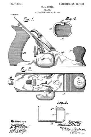
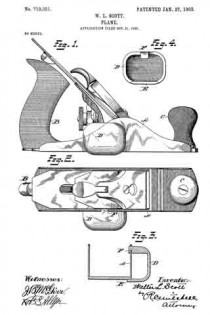
In the drawings, Figure 1 is a side elevation of a plane with the detachable handle applied thereto. Fig. 2 is a plan view. Fig. 3 is a cross-section of the plane-stock and detachable handle, as shown in Fig. 1. Fig. 4 is a view of the inside of the detachable handle.

A represents the stock of an iron plane. B is a handle permanently attached to the rear end thereof.

C is a front knob or handle, also usually permanently attached to the stock A. In ordinary use the operator grasps the two handles B C, The other details of the plane proper, such as the knife and the adjusting devices, it is unnecessary to describe in detail herein, because they constitute no part of this invention.

D is the body of a detachable handle, preferably in the form of a shell, since it provides a strong and light construction.

E is a lip on one side of the body D, the same being by preference of sufficient length to give a long flat bearing. Obviously the number of these lips E is immaterial. Two short lips spaced apart would give the same result. The lip E will for convenience of expression be termed herein the “fiat” lip. F is a hooked lip at the opposite side of the body D, the hook facing the flat lip E. Ordinarily the stock A of a metal plane is provided with cheek-pieces, one on each side, and these cheek-pieces are generally shaped as shown in Fig. 1, in which they incline upwardly from each end to a high point or crown.

In attaching the handle-body D the flat lip E is placed against the bottom of the plane-stock, and the handle is then pushed forward toward the highest part of the cheek-piece until the hooked lip F engages with it and may be wedged thereon, the hook of the lip F overstanding the upper edge of the cheek-piece and securing the handle in place on the side of the plane. The operator may then use the plane with one or both hands.

In case one hand is used the palm is placed against the rear side of the body D and the fingers are placed over the top of the plane, giving a secure grip. The position of the plane will then be on its side and the same may be pushed along the side or edge of the thing to be planed and the work done with ease and accuracy. In case the operator desires to use two hands he may grasp the solid handle B with one hand and the detachable handle D with the other, the latter taking the place of the knob-handle C. When the work is completed, the handle D may be easily removed by sliding the same backward and freeing the hook F from the cheek-piece of the stock.

Obviously the particular shape of the handle and its particular construction may be varied and modified in such ways as will suggest themselves to the mechanic skilled in the art without departure from the spirit and scope of this invention.

What I claim is —

1. A side handle for a plane comprising a body portion and means projecting from said body for detachably engaging the same at the side of a plane-stock.

2. A side handle for a plane comprising a body portion and means for frictionally engaging the same with the cheek-piece of the plane-stock.

3. A side handle for a plane comprising a body portion D, a flat lip on one side, and a lip on the opposite side said lips adapted to engage with the plane-stock.

4. A side handle for a plane comprising a body portion D, a flat lip at one edge thereof, and a hooked lip at the opposite edge thereof.

5. A side handle for a plane comprising a body portion, a lip on one edge thereof, a lip on the other side thereof, one of said lips being hooked.

Signed at San Francisco, California, this 10th day of October, 1902.

WALTER L. SCOTT.

Witnesses:
GEORGE PATTISON,
J. W. WRIGHT.

No. 679,424 – Plane (Ludwig Kemline) (1901)

[paiddownloads id=”553″]679424


UNITED STATES PATENT OFFICE.

_________________

LUDWIG KEMLINE, OF PINOLE, CALIFORNIA.

PLANE.

_________________

SPECIFICATION forming part of Letters Patent No. 679,424, dated July 30, 1901.
Application filed October 27, 1900. Serial No. 34,625. (No model.)

_________________

To all whom it may concern:

Be it known that I, LUDWIG KEMLINE, a citizen of the United States, and a resident of Pinole, in the county of Contra Costa and State of California, have invented a new and Improved Plane, of which the following is a full, clear, and exact description.

The purpose of this invention is to provide a plane or other tool with a handle which may be adjusted transversely of the plane, so as to place the hand of the user in any position desired with respect to the transverse extent of the plane. By these means the operator may avoid bruising his hands or otherwise interfering with the work when it is of such character as will make it inconvenient to use the tool with the handle in the middle thereof.

This specification is the disclosure of one form of the invention, while the claims define the actual scope thereof.
Reference is to be had to the accompanying drawings, forming a part of this specification, in which similar characters of reference indicate corresponding parts in both views.

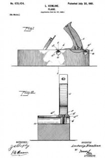
Figure 1 is a side view of the invention with parts in section, and Fig. 2 is a section on the line 2 2 of Fig. 1.

The plane is constructed in the usual manner, except that the body is formed with two transverse grooves a, which open at the upper side of the body and which are undercut, as shown. The cross-sectional form of the grooves a is immaterial so long as the opening at the top of the grooves is of less width than the opening below the top. The purpose of this is to hold in the grooves the blocks b in such a manner as to prevent the blocks from moving upward or transversely out of the grooves. These blocks are freely movable longitudinally of the grooves, however, and the handle c of the plane is attached to the blocks through the medium of a face-plate d and screws e, passing through the base-plate and into the blocks, as best shown in Fig. 2. The base-plate d is provided with transverse ribs d’, which fit in the upper sides of the grooves a, and serve to assist in holding the base-plate in position. The base-plate is preferably of metal and fastened to the handle c by screws or other devices, as shown.

Having thus described my invention, I claim as new and desire to secure by Letters Patent —

1. A plane or analogous tool having an undercut groove in the upper side thereof, said groove extending transversely of the plane, a block adjustably mounted in the groove, a handle, a base-plate on which the handle is mounted, and a fastening device extending between the base-plate and block to bind the block against the walls of the groove and adjustably hold the handle.

2. A plane or analogous tool having two undercut grooves formed in its upper side, said grooves extending transversely of the plane, a block adjustable in each groove, a base-plate extending from one groove to the other and having ribs fitting in the grooves, fastening devices extending between the block and the base-plate, and a handle fastened to the base-plate.

In testimony whereof I have signed my name to this specification in the presence of two subscribing witnesses.

LUDWIG KEMLINE.

Witnesses:
JAMES SILVAS,
A. McCULLOUGH.

No. 659,287 – Bench-Plane (Edward O. Carvin) (1900)

[paiddownloads id=”548″]659287


UNITED STATES PATENT OFFICE.

_________________

EDWARD O. CARVIN, OF VALLEY SPRINGS, CALIFORNIA,
ASSIGNOR OF ONE-HALF TO T. J. FRENCH, OF SAME PLACE.

BENCH-PLANE.

_________________

SPECIFICATION forming part of Letters Patent No. 659,287, dated October 9, 1900.
Application filed June 14, 1900. Serial No. 20,364. (No model.)

_________________

To all whom it may concern:

Be it known that I, EDWARD O. CARVIN, a citizen of the United States, residing at Valley Springs, in the county of Calaveras and State of California, have invented certain new and useful Improvements in Planes; and I do hereby declare the following to be a full, clear, and exact description of the invention, such as will enable others skilled in the art to which it appertains to make and use the same.

This invention relates to carpenters’ planes, and more particularly to the means whereby the handle is susceptible of adjustment to a variety of positions to meet diiferent conditions to facilitate the work and secure ease and comfort to the workman.

The improvement consists of the novel features and the details of construction, which hereinafter will be more fully set forth, and finally pointed out in the appended claims.

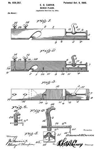
In the drawings, Figure 1 is a side elevation of a plane constructed in accordance with and embodying the essential features of the invention. Fig. 2 is a central longitudinal section thereof. Fig. 3 is a top plan view, parts being broken away. Fig. 4 is a detail view showing different mountings for the handle. Fig. 5 is an end view of the construction shown in Fig. 4. Fig. 6 is a detail view showing different means for securing the handle in an adjusted position.

Corresponding and like parts are referred to in the following description and indicated in all the views of the drawings by the same reference characters.

The body 1 of the plane may be of any size and pattern, according to the style of plane, and is provided with a throat 2, adapted to deliver the shavings at one side of the plane, said throat extending transversely of the body and flaring from one side thereof to the other. The rear or heel portion of the body is reduced in depth to enable the handle 3 to be as low down as possible, and the heel portion 4 is reinforced by a horizontal plate 5, secured thereto and provided at its ends with vertical extensions 6 and 7, the latter projecting above and below the plate 5, as shown, the upper extension receiving the rear end of the handle-support 8 and the lower extension overlapping the rear end of the heel portion 4. The parts 5, 6, and 7 are of integral formation and are secured to the parts of the body in any substantial manner. The bit 9 is secured to the lower face of the body 1 in the rear of the throat 2 and is adjustable longitudinally to compensate for wear incident to sharpening. Clamp-screws 10 are let into the body 1 and their heads fit countersunk portions of longitudinal slots 11, formed in the bit, so as not to project beyond the lower face thereof. After the bit has been properly positioned it is secured by tightening the clamp-screws 10, and in order to prevent possible slipping of the bit the latter is formed upon its top side or the face adapted to lie adjacent to the lower side of the body 1 with transverse serrations or Iine teeth 12, which bite into the face of the body and positively hold the bit in the adjusted position after the clamp-screws have been properly tightened. The bit 9 protects the lower face of the body 1 and by being disposed in the manner set forth operates by a more direct cut, whereby knots and timber are adapted to be readily cut across grain.

In order to regulate the depth of out or thickness of shaving, a gage-plate 13 is located in advance of the throat 2 and is vertically adjustable, any suitable means being employed to effect this result, and, as shown, companion set-screws let are threaded into the body of the plane and make swivel connection at their lower ends with bosses provided upon the top side of the gage-plate 13, said set-screws being adapted to be turned by means of thumb-buttons 15 at their upper ends. Jam-nuts 16 are fitted to the set-screws 14 to hold the latter in the required position. By turning the set-screws either to the right or to the left the gage-plate can be lowered or raised, according to the desired thickness of shaving to be cut.

The handle-support 8 is a rod or bar centrally disposed with reference to the body 1 and secured at its ends to the vertical extensions of the plate 5. The handle 3 is adjustable on the support 8, so as to be brought nearer to the cutting edge of the bit or farther away therefrom, according to the nature of the work and the convenience to the user. The handle, in addition to its longitudinal adjustment with reference to the plane, can be turned to any desired angular position either to the rightor to the left, thereby enabling the plane to be used in angles and close quarters, where it would be inconvenient to grasp the handle and manipulate the plane if said handle occupied a vertical position. Any means may be employed for securing the handle in the required position, and, as shown in Figs. 1, 2, and 3, a pair of nuts 17 is mounted upon the rod 3, which latter is screw-threaded throughout its length, the handle 3 being clamped between the nuts of the pair.

In the construction shown in Figs 4 and 5 the rod or bar 8a is formed in a side with a series of openings 18, and the handle 3 is provided with a spring-actuated pin 19 to enter any one of the openings 18 and hold the said handle in an adjusted position, the pin 19 being operated by means of a thumb-latch 20, pivoted to the offset portion of the handle. This support 8a is mounted in the vertical extensions of the plate 5 so as to turn and is provided at its rear end with a spring-arm 21, provided with a stud 22 to enter one of a series of openings 23, formed in the rear face of the vertical extension 7, whereby the handle is positively secured when turned either to the right or to the left from a vertical position. The construction is such as to admit of the body 1 being formed of wood, the plate 13 and the bit 9 forming a metal surface for the lower side thereof to protect it from wear and injury. The depression of the bit enables it to operate by a more direct cut, whereby it will pass more easily through knotty wood and across grain without disturbing the fibrous structure of the material to such an extent as to leave a rough surface commonly experienced when dressing knotty timber by planes of ordinary construction. In the event of the body 1 being of metal or other material the plate 13 and the bit 9 form a facing therefor.

Fig. 6 shows the handle 3 mounted upon a smooth rod 8b and provided with a clamp device consisting of rod 24, having its inner end portion threaded to coact with a nut 25, let into the handle and having its outer end bent, as at 26, to form a grip for turning the rod to release or secure the handle.

Having thus described the invention, what is claimed as new is —

1. In combination with a carpenter’s plane, a handle adjustable lengthwise of the plane and to any angular position, and means for securing the handle in an adjusted position, substantially as set forth.

2. A carpenter’s plane having its rear portion rednced upon its top side for a short distance from its rear end, a support disposed parallel of the plane and located above the heel thereof, and a handle adjustably mounted upon the said support, substantially as specified.

3. In combination with a carpenter’s plane, a support mounted so as to be turned about its axis, means for turning said support and securing it in an adjusted position, and a handle adjustable on the said support, substantially as specified.

In testimony whereof I affix my signature in presence of two witnesses.

EDWARD O. CARVIN. [L. S.]

Witnesses:
JAMES B. LUDDY,
F. J. SOLINSKY.

No. 518,823 – Lubricator (Royal W. McIntyre And Gustavus A. H. Sprague) (1894)

[paiddownloads id=”507″]518823


UNITED STATES PATENT OFFICE.

_________________

ROYAL W. McINTYRE AND GUSTAVUS A. H. SPRAGUE, OF REDLANDS, CALIFORNIA.

LUBRICATOR.

_________________

SPECIFICATION forming part of Letters Patent No. 518,823, dated April 24, 1894.
Application filed January 23, 1893. Serial No. 459,385. (No model.)

_________________

To all whom it may concern:

Be it known that we, ROYAL WARNER McINTYRE and GUSTAVUS ADOLPHUS HANKINSON SPRAGUE., of Redlands, in the county of San Bernardino and State of California, have invented certain new and useful Improvements in Oil-Cups; and we do hereby declare the following to be a full, clear, and exact description of the invention, such as will enable others skilled in the art to which it appertains to make and use the same.

Our invention is an improvement in oil cups or cans designed for greater simplicity and durability of construction and efficiency and certainty of operation.

A further object of our invention is to supply simple and useful means for lubricating the under surface of iron planes thereby dispensing with the old method of greasing the under surface of the plane with a piece of fat.

Other objects and advantages of the invention will appear in the following description in which we have set forth fully the details of construction and the essential features thereof and illustrated them in the accompanying drawings in which similar letters of reference designate corresponding parts.

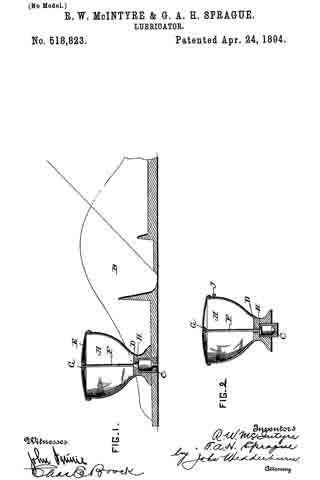
Figure 1 represents a part section and side view of an ordinary plane with our invention attached. Fig. 2 is a modification.

Reference being had to the above figures A represents the main body of the oil cup which is secured to the forward portion of the plane B by means of the hollow threaded lug C. The bottom of the cup A is provided with the conical hole D the smaller end of which is at the upper surface of the bottom. The upper portion of the cup A is furnished with a convex screw cap E which is made of light spring material and is screwed to the cup in the manner shown in Fig. 1. Extending upward through the conical hole D is the valve rod F one end of the stem of which is screwed to the projection G on the under surface of the cap E while its other end terminates in a conical enlargement H corresponding to the opening in the lower surface of the cup A. It will be readily seen that when the cap E is pressed downward the valve stem F and enlargement H are forced downward thus allowing the oil to flow through the hole in the bottom of the cup A thereby lubricating the under surface of the plane.

In Fig. 2 we have changed the construction slightly and instead of the conical hole D we have substituted a hole with parallel sides and constructed the enlargement H to correspond. In this latter construction the cup is adapted to be filled through the opening in the side of the cap near the top which is closed by a screw J. It will be readily seen that it is impossible for the oil to escape from the nozzle unless the base of the can is forced inward.

The construction and arrangement of the several parts of our invention being thus made known the operation and advantages of the same will it is thought be readily understood.

Having thus fully described our invention, what we claim, and desire to secure by Letters Patent, is —

The combination with a plane, having an opening through the bed of the front portion thereof, of an oil cup resting on said bed, and having a spring actuated valve therein which is operated from the upper end, and a screw plug, C, seated within the perforated base of the cup with an opening therethrough by means of which the said oil cup is secured to the bed plane, the upper portion of said plug being formed with an enlarged chamber, with which said valve communicates, and a lower reduced opening, and the lower end of said plug extending only partially through the side of the plane, substantially as described.

In testimony whereof we have signed this specification in the presence of two subscribing witnesses.

R. W. McINTYRE.
G. A. H. SPRAGUE.

Witnesses:
NAT A. BLAKE,
O. A. MOSTLING.

No. 511,349 – Plane (Henry Merz) (1893)

[paiddownloads id=”498″]511349


UNITED STATES PATENT OFFICE.

_________________

HENRY MERZ, OF POLLASKY, CALIFORNIA.

PLANE.

_________________

SPECIFICATION forming part of Letters Patent No. 511,349, dated December 26, 1893.
Application filed May 1, 1893. Serial No. 472,568. (No model.)

_________________

To all whom it may concern:

Be it known that I, HENRY MERZ, of Pollasky, in the State of California, have invented certain new and useful Improvements in Planes; and I do hereby declare the following to be a full, clear, and exact description of the invention, such as will enable others skilled in the art to which it appertains to make and use the same.

This invention relates to planes for carpenters and the like, and has for its object to improve devices of a similar character which have been heretofore employed.

The invention consists of the detail construction, combination and arrangement of parts, substantially as hereinafter fully set forth, and particularly pointed out in the claims.

In the accompanying drawings: — Figure 1 is a vertical longitudinal sectional view of my improved plane. Fig. 2 is a view of the cutting blade detached. Fig. 3 is a perspective view of the cap-plate, screw and adjuncts. Fig. 4 is a detail perspective view of a part of the adjusting mechanism. Fig. 5 is a bottom plan view of the cap plate and adjustments in connection therewith. Fig. 6 is a rear end elevation of the clamp and cap plate.

Referring to the drawings, A designates the main or body portion of the plane, having the ordinary opening a which terminates in the transverse slot a’ through which the cutting blade B projects. In this cutting blade is a T-shaped opening, in the outer end of which is a lug b forming a pivot point. In the rear inclined wall of opening a is set a metallic plate b’ into a threaded opening in which is screwed a screw C, the head d of which has an overhanging lower flange d’.

D is a cap plate having a longitudinal slot d2, and a rear central cut away portion d3, and two corresponding sockets d4 on either side of said cut-away portion. To the under side of this cap-plate is fastened a spring-plate E from which extend parallel arms e free at their outer ends.

F is a clamp which fits between sockets d4 and is pivoted by a rod f supported by said sockets. This clamp is rounded at its pivoted end and is provided with two curved cam-lugs f’, which when the clamp is lowered will extend through the cut-away portion of the cap-plate and bear upon the free ends of the spring-arms, causing the latter to bind against the upper surfaces of the cutting blade.

G is a block having upper shoulders g, and a threaded projection g’ which is extended up through slot d2 of cap-plate D and upon it is screwed a nut g2 designed to bind against a washer g3 extending across said slot. The shoulders g are drawn against the lower walls of slot d2, said walls being made tapering. The lower end of block G has an acute lip g4 extending therefrom and designed to engage with the overhanging portion of the headed screw G. The lip is formed into somewhat of a point at about its center so as to securely engage the head of the screw and be held stationary. Through a threaded opening in this block extends a screw rod H, which fits in the T-shaped opening of the cutting blade. A socket in the outer end of this screw-rod receives the lug b. Adjacent to this end is a milled head h, by which the screw rod is readily and easily turned.

The operation of my improved plane is readily understood from what has gone before. To quickly effect the adjustment of the cutting blade the operator raises the clamp so as to release the frictional engagement between the cutting blade and cap-plate, permitting the spring arm to be free. By turning the screw rod the cutting blade can be moved in either direction, the block secured to said cap-plate being stationary by reason of the engagement with the screw C. After the cutting blade has been adjusted the operator closes down the clamp and the cam-lugs thereof bind the spring arms down on said cutting blade, making a firm frictional contact therewith and holding the cutting blade in position. By turning the screw-rod the cutting blade can still be further adjusted but is firmly held at any desired point, the cap-plate being stationary by reason of the engagement of the acute lip of the block with the head of the screw C.

The advantages of my invention are apparent to those skilled in the art to which it appertains, and it will be specially observed that the mechanism employed is simple and not liable to readily get out of order.

I claim as my invention —

1. The herein described plane, comprising a body with a slot or opening therein, a headed stud or screw C arranged obliquely and having a flanged head, a blade having a longitudinally disposed slot with a pivot at the central upper portion of the same, a cap plate with a slot therein in which is adjustably mounted a block formed with a shouldered groove engaging said flanged head of the stud or screw, and having a screw threaded opening extended transversely therethrough, a spring clamp having its upper end pivotally connected to the upper portion of the said cap plate, and a screw rod located in the said longitudinally disposed slot of the blade, and having a milled nut thereon whose upper end engages the pivot at the upper end of said slot in the blade, said nut being located in the slot, substantially as described.

2. The herein described plane comprising a body having a stud or screw therein with a flanged head, a blade having a longitudinally disposed slot with a pivot at the upper terminating wall of the same, a cap plate provided with a slot and having sockets at the upper portions of the same with a central cutaway part, a block adjustably mounted in the slot of the cap plate, and formed with a lower shouldered groove to engage the flanged head of the said stud or screw, a spring clamp mounted on the cap plate and having its upper end pivotally located in the cut-away part of the latter, and pivoted to the sockets thereof, having parallel arms e, which are free and bear against the blade to produce a spring action and a screw rod H mounted in the longitudinally disposed. slot of the blade and extending through the aforesaid block, said screw rod having a milled nut on the upper end thereof for adjusting the blade and having its upper surface rotatably engaging the said pivot, said nut being revoluble in the slot of the blade, substantially as described.

In testimony whereof I have signed this specification in the presence of two subscribing witnesses.

HENRY MERZ.

Witnesses:
W. R. THOMAS,
G. M. McGUIRE.

No. 502,906 – Plane (Louis Hardt) (1893)

[paiddownloads id=”491″]502906


UNITED STATES PATENT OFFICE.

_________________

LOUIS HARDT, OF YUBA CITY, CALIFORNIA.

PLANE.

_________________

SPECIFICATION forming part of Letters Patent No. 502,906, dated August 8, 1893.
Application filed November 3, 1892. Serial No. 450,873. (No model.)

_________________

To all whom it may concern:

Be it known that I, LOUIS HARDT, a citizen of the United States, residing at Yuba City, Sutter county, State of California, have invented an Improvement in Planes; and I hereby declare the following to be a full, clear, and exact description of the same.

My invention relates to planes and it consists, broadly, in a stock the sole of which in advance of the main body portion and the bit iron is vertically and longitudinally adjustable with respect to the main body portion and bit iron, the adjustment in one direction causing the adjustment in the other direction whereby the depth of the cut and capacity of the throat are simultaneously increased.

The main object of my invention is to provide for an adjustable exposure of the cutting edge of the bit-iron without changing the position of the iron.

Another object is, by the peculiar adjustable front piece, to not only regulate the exposure of the cutting edge of the bit-iron, but also to vary the capacity of the throat.

The accomplishment of these objects results in providing a plane easily set to the different kinds of work, said plane having a perfect bearing surface or guide behind the knife, whereby it cuts true and smooth.

Referring to the accompanying drawings for a more complete explanation of my invention, — Figure 1 is a longitudinal, vertical section of my plane. Fig. 2 is a vertical transverse seetion on the line x–x of Fig. 1.

A is the flat-soled stock of the plane having the usual handle or toat B. In the stock is made the bed a in which is seated the bit-iron C held to place by the usual wedge D.

E is my movable or adjustable front piece of the stock. This is secured to the front of the stock in such a manner that it can move to and be fixed at diiferent heights, thereby exposing to a greater or less extent the cutting edge of the iron C. This front piece E forms the base or sole of the front portion of the stock, and it is obvious than when its sole is in line with the sole of the stock there is a perfectly smooth under surface throughout the length of the stock, and the cutting edge of the iron may come down to the plane of this surface, in which case it will not cut at all; but by moving the front piece E to a higher plane the cutting edge of the iron will be exposed, and by starting the plane at the end of the board it will cut a shaving equal in thickness to the exposure of said cutting edge, due to the elevation of the front piece E; or by starting the plane in the middle of the board and pressing down upon its forward edge, the cutting edge of the iron may catch a thin shaving and so start the necessary abutment or ridge behind which the iron may work forwardly, to plane the surface of the board. It is obvious that this movement of the piece E to different heights may be accomplished vertically, if desired. But I prefer, mainly for two reasons, namely, the accurate adjustment of the piece, and the varying of the capacity of the throat, to effect the imovement of the adjustable piece E upon an inclined plane, so that it moves both vertically and forwardly. To this end it will be seen that the top edge of the front piece E is inclined and fits under a corresponding incline on the undercut front of the stock in suitable guides therein, as shown in Fig. 2, so that its upward and forward movement is accurate. To hold this front piece in place and set it where adjusted, I have the following connections:

F is a vertical bolt passing down through an elongated slot a’ in the front portion of the stock and entering the piece E, its lower end engaging a nut f countersunk in said piece. The upper end of this bolt is provided with the head, furnishing a hand-hold G. By loosening this bolt the front piece E may be moved forwardly on its inclined plane, the bolt F moving in the slot a’; and it may be again tightened to hold the base E in the position desired.

In order to firmly secure the piece E, which on account of its inclined character, would be difficult with the bolt F alone, I have the horizontal stay bolt H which passes through an enlarged opening e in the movable front piece E, and enters the front of the stock A where it engages a countersunk nut h in said portion of the stock. This bolt has a head h’ whereby it may be easily operated. When bolt H is loosened the piece E may be moved. It will now be seen that by moving the front piece E forwardly and upwardly, its rear end will not only expose the cutting edge of the bit-iron C, but will also enlarge the throat. In a plane of this construction, there is no necessity for changing the position of the iron at all; but in case it be desired to reach hollow places the iron can be set out in the usual manner. For the planing of ordinary surfaces, however, the iron remains stationary and its set is effected by the adjustment of the front piece E. This plane has, therefore, a full and complete smooth bearing on the base or sole of its stock behind the iron, at all times, instead of as is usual, the formation of a hollow place behind a projecting iron, which has a tendency to produce a rocking of the stock.

In my plane a start can be made without resulting in a notch or imperfect place, and the set of the iron may be rapidly and accurately had by holding the plane at the end of the board and setting the front piece up to expose the required portion of the iron.

Having thus described my invention, what I claim as new, and desire to secure by Letters Patent, is —

1. In a plane, a stock the sole of which in advance of the main-body-portion and the bit-iron is vertically and longitudinally adjustable with respect to the main body-portion and bit-iron the adjustment in one direction causing the adjustment in the other direction, whereby the depth of the cut and capacity of the throat are simultaneously increased, substantially as herein described.

2. In a plane, a flat-soled stock having its forward end undercut on an upward incline in combination with a movable front piece forming the sole of the stock having a downward inclined upper surface in advance of the bit-iron, said piece having a downward inclined upper surface fitted under the inclined front of the stock, whereby it may move forwardly and upwardly to increase the exposure of the cutting edge of the iron and the capacity of the throat, substantially as herein described.

3. In a plane, a flat-soled stock having its forward end undercut on an upward incline, in combination with a movable front piece forming the sole of the stock in advance of the bit-iron, said piece having a downward inclined upper surface fitted under the inclined front of the stock whereby it may move forwardly and upwardly to increase the exposure of the cutting edge of the iron and the capacity of the throat, and suitable bolts connecting said front piece to the front of the stock, substantially as herein described.

4. In a plane, the combination of the flat-soled stock with its upward inclined undercut front, the fiat-soled movable front piece E of the stock having a downward inclined upper surface fitted to the inclined undercut front, and the securing bolt F fitted to said piece and movable in the front of the stock whereby the depth of the cut and the capacity of the throat are simultaneously increased, substantially as herein described.

5. In a plane, the combination of a flat sole stock with its upward inclined undercut front, the fiat sole movable front piece E of the stock having a downward inclined upper surface fitted to the undercut front the securing bolt F fitted to said piece and movable in the front of the stock, and the horizontal stay bolt F fitted to the front of the stock and piece E, whereby the depth of the cut and the capacity of the throat may be simultaneously increased, substantially as set forth.

In witness whereof I have hereunto set my hand.

LOUIS HARDT.

Witnesses:
H. A. SCHULTZE,
WM. F. BOOTH.

No. 464,701 – Plane Attachment (George H. Melendy) (1891)

[paiddownloads id=”480″]464701


UNITED STATES PATENT OFFICE.

_________________

GEORGE H. MELENDY, OF SAN FRANCISCO, CALIFORNIA,
ASSIGNOR OF ONE-HALF TO BENNETT BROTHERS, OF SAME PLACE.

PLANE ATTACHMENT.

_________________

SPECIFICATION forming part of Letters Patent No. 464,701, dated December 8, 1891.
Application filed January 14, 1891. Serial No. 377,761. (No model.)

_________________

To all whom it may concern:

Be it known that I, GEORGE H. MELENDY, a citizen of the United States, residing in the city and county of San Francisco, State of California, have invented an Improvement in Plane Attachments; and I hereby declare the following to be a full, clear, and exact description of the same.

My invention relates to an attachment for planes such as are in use by carpenters and others; and it consists, essentially, of means for adjusting and compensating the throat to the wear which takes place upon the bottom face of the plane by constant use, and in certain details of construction.

Referring to the accompanying drawings for a more complete explanation of my invention, Figure 1 is a longitudinal vertical section taken through the front of the plane showing the adjustment thereof. Fig. 2 is a view showing the throat-adjusting block removed. Fig. 3 is a perspective view of the front end of my plane.

A is the body of the plane having the handle B and the open throat C within which the plane-iron is fixed in any usual or suitable manner. When these plane~bodies are made of wood, they are subjected to considerable wear by reason of the friction of the lower face with the surface over which they are moved and which the plane-iron is intended to cut and dress, and as this wear takes place the throat for the escape of the shavings loses its proper proportion, thus necessitating some adjustment if the plane is to have any further use. In my invention I have shown the throat having an inclined chamber D made in the forward portion of it by inserting a piece E, a portion of the under surface of which is inclined and projects into the throat and forms the top wall of the inclined chamber, this chamber inclining into the forward portion of the body A. This piece E, which forms the chamber D, is designed to protect the adjustable block F and moving parts from dust or shavings, and it is important for the reason that without it they would become choked and clogged. Within this chamber below the block E is fitted a block F, the front portion of which rests upon the front portion of the incline in the chamber D, and the rear portion is made with two faces G and G’, meeting each other at an angle, as shown, the face G’ being approximately vertical when the plane is in its ordinary position. Through the upper portion of this block slots are made and screws H serve to fix it at any desired point.

When by considerable use the plane has been worn down, it will be manifest that by reason of the inclined rear face of the opening C upon which the plane-iron is supported the throat will become enlarged and will not be in proper shape for the best work. When this occurs, the screws or fastening of the movable throat-piece are loosened, and this piece is allowed to move downward, sliding upon the inclined surface of the front of the chamber, and this forces the surface G’ of the movable block nearer to the edge of the plane-iron. The block is moved downward until the throat is made of the proper size, when it is again secured in place. The lower end of the block which would be projected beyond the surface of the plane by this movement is cut off so that it is again flush with the surface of the plane. By this device the throat of the plane may be adjusted and retained at the proper size until the plane is entirely worn out. In connection with this device I have shown the inserted block I, having a rounded or convex surface, fitted into a channel or groove of semicircular form in cross-section, which is formed vertically in the front end of the plane. This block is secured in the channel with the grain of the wood extending vertically, so that the end grain is exposed at the bottom and flush with the surface of the plane. The object of this is to equalize the wear upon the plane, as it is well known that the front end of the plane which is first pushed over the rough surfaces of the work to be planed is worn and rounded off more rapidly than the other portions which are situated behind the plane-iron, and by reason of this hard inserted piece and the fact that the wear comes upon the end of the grain the wear will be equalized and the plane kept in proper condition much longer.

Having thus described my invention, what I claim as new, and desire to secure by Letters Patent, is —

1. In a plane having a plane-iron and a throat, a piece E, let into the throat so as to form an inclined chamber, an adjustable block in said chamber below the piece E, and screws passing through and adjustably securing the block, substantially as herein described.

2. In a plane, the body thereof having its front end formed with a vertical groove semi-circular in cross-section, and a piece having a convex rear surface fitting the groove so that its lower end is flush with the bottom of the plane, said inserted piece having its grain at right angles with the grain of the body, whereby it presents an end grain surface at the bottom to equalize the wear upon the plane, substantially as herein described.

In witness whereof I have hereunto set my hand.

GEORGE H. MELENDY

Witnesses:
A. B. MERRILL,
J. W. RICHARDS.

No. 459,122 – Plane (James K. Kendrick) (1891)

[paiddownloads id=”478″]459122


UNITED STATES PATENT OFFICE.

_________________

JAMES K. KENDRICK, OF GERMANTOWN, CALIFORNIA.

PLANE.

_________________

SPECIFICATION forming part of Letters Patent No. 459,122, dated September 8, 1891.
Application filed March 20, 1891. Serial No. 385,803. (No model.)

_________________

To all whom it may concern:

Be it known that I, JAMES K. KENDRICK, a citizen of the United States, residing at Germantown, in the county of Colusa and State of California, have invented certain new and useful Improvements in Planes; and I do declare the following to be a full, clear,and exact description of the invention, such as will enable others skilled in the art to which it appertains to make and use the same, reference being had to the accompanying drawings, and to the letters of reference marked thereon, which form a part of this specification.

My invention has relation to improvements in plane-guides; and it consists in the construction, novel combination, and adaptation of parts hereinafter described and claimed.

The invention will be fully understood from the following description and claim when taken in conjunction with the annexed drawings, in which —

Figure 1 is a side elevation of a plane provided with my irnproved guide; and Fig. 2 is an end elevation of the same in conjunction with a piece of wood, illustrating the relative position of the plane and guide with respect to each other and the wood when itis desired to bevel one corner of the latter.

Referring by letter to the said drawings, A indicates a jack-plane, which may be of any approved construction, and B indicates the bit thereof. Permanently connected to the left-hand side of the plane by screws C’ or the like is the flat stationary section C of my improved guide, the lower portion of which is forked and depends below the bottom of the plane, as illustrated.

D indicates the adjustable section of my improved guide, which is also flat, and has its upper portion tongued, as illustrated, to take between the depending fork branches of the stationary section, to which it is pivotally connected by a transverse bolt E, which takes through the fork branches of the stationary section and the tongue portion of the adjustable section, and has one of its ends threaded to receive a wing-nut E’, which serves to secure the bolt in position. By this construction of guide, which comprises but four parts and may be made of hard wood or the like, it will be seen that a cheap and efficient guide is afforded without rnaterially increasing the weight of the plane, and by the provision of the wing-nut E’ it will be readily perceived that the adjustable section may be readily removed and another section placed in position when desirable.

Having described my invention, what I claim, and desire to secure by Letters Patent, is —

The combination, with a plane, of the guide consisting of the flat section C, permanently attached to the side of the plane and having its lower portion forked, the flat adjustable section D, having its upper portion tongued or reduced to take between the fork branches of the section C, the bolt taking through the fork branches of the section C and the tongue of section D and having its end threaded, and a wing-nut mounted on the threaded end of said bolt, substantially as specified.

ln testimony whereof I affix my signature in presence of two witnesses.

JAMES K. KENDRICK.

Witnesses:
P. H. CLARK,
L. H. HILL.

No. 394,411 – Bench-Plane (William Stevenson) (1888)

[paiddownloads id=”443″]394411


UNITED STATES PATENT OFFICE.

_________________

WILLIAM STEVENSON, OF DOUGLAS FLAT, ASSIGNOR OF
ONE-HALF TO JOHN MONTEVERDA, OF STOCKTON, CALIFORNIA.

BENCH-PLANE.

_________________

SPECIFICATION forming part of Letters Patent No. 394,411, dated December 11, 1888.
Application filed April 18, 1888. Serial No. 271,087. (No model.)

_________________

To all whom it may concern:

Be it known that I, WILLIAM STEVENSON, of Douglas Flat, Calaveras county, State of California, have invented an Improvement in Combination-Planes; and I hereby declare the following to be a full, clear, and exact description of the same.

My invention relates to the class of planes in which blades of different character are combined in the same stock; and my invention consists in the novel stock, the double-ended blades and their manner of arrangement, and means for adjusting them in the stock, as I shall hereinafter more fully describe.

The object of my invention is to provide a plane of simple construction, and which, by reason of its different blades, is adapted for several uses.

Referring to the accompanying drawings for a more complete explanation of my invention, Figure 1 is a perspective view of my combination-plane. Fig. 2 is a top view of same. Fig. 3 is a side elevation of the stock, the securing-plate d being removed to show the blade and its operative mechanism.

A is the stock of the plane, having its upper and lower edges made with central longitudinal guides, a, thus dividing it into four working-surfaces, one being on each side of the central guide of each edge. These surfaces in any given stock may be made in the proper shape or contour to suit the several uses intended for that particular combination-tool. In the present instance, in order to illustrate this fully, I have shown two of the surfaces — one on each edge and on the same side of the guides a — as “matching” surfaces — that is, one is for a “tongue” and the other is for a “groove.” The remaining two surfaces I show as a simple “nosing” surface and a “molding” surface. I do not confine myself to them, however, for my invention contemplates the making of any suitable surfaces, the essential feature of the stock in this respect being its construction, providing for any four working-surfaces.

In each side of the stock are made two throat-sockets, B, which are arranged in reversed position with relation to each other, and also in each side of the stock is made a groove-seat, C, opening at each end into one of the working-surfaces and near each end into a throat-socket. Into these grooves C are fitted the blade-guides D, which are secured in place by plates d, let in flush with the sides of the stock and secured thereto by screws d’. Fitted in one side of each of these blade-guides is a rotary pin, e, which carries a pinion, E, the teeth of which project into the guide far enough to engage the rack-teeth of the blades, as I shall presently explain.

Upon the outer end of each pin e (which projects through the securing-plate d) is fixed a lever-arm, F, having at one end a small thumb-piece, f, by which it may readily be turned to turn the pin axially and rotate the pinion, and in the other end said lever-arm carries a set-screw, f’, the lower end of which is made to come in contact with the plate d, whereby the arm may be firmly set in the position to which it may be turned, thus holding the pinion rigidly.

G are the bits. I have shown two. Each is a double-ender-that is to say, a cutting-edge is made on each end. I do not confine myself to the particular shape or character shown on these planes, for they are made to adapt them to the uses intended and corresponding to the working-surfaces of the particular stock they are designed to fit. In this case I have shown a matching-edge on each end of one of the bits, and on the other I have shawn a nosing-edge on one end and a molding-edge on the other end. There are therefore four edges in the set. Each of these bits is formed or provided with rack-teeth g. These bits are fitted through the guides D, so that their rack-teeth are engaged by the pinion E, and their edges extend through the ends of the groove-seats C into proper position along the working-surfaces of the stock. They are made of such a length that when the edge on one end is projected for proper operation in connection with its working-surface the edge on the other end is withdrawn from its working-surface, so as not to be in the way when handling the tool.

The operation is as follows: When I wish to use the grooving-edge, I turn the lever-arm F by the thumb-piece f in a direction and to an extent sufficient to cause the pinion E to project said edge to working position, (the edge on the other end being withdrawn out of the way by the same movement,) and I then fix it in position by setting the screw f’. The operation is the same with any of the other edges.

Having thus described my invention, what I claim as new, and desire to secure by Letters Patent, is —

1. In a combination-plane, a bit having a cutting-edge on each end and having rack-teeth formed on one of its sides, substantially as herein described.

2. In a combination-plane, a stock having a working-surface on its upper and lower edges, in combination with a bit fitted to the stock and having a cutting-edge on each end, and an adjusting device for operating the bit, so that when its cutting-edge on one end is projected into position along its corresponding working-surface the cutting-edge on its other end is withdrawn from its working-surface, substantially as herein described.

3. In a combination-plane, a stock having a working-surface on its upper and lower edges, in combination with a bit fitted to the stock and having a cutting-edge on each end and rack-teeth on its side, and the mechanism for adjusting the bit, as described, consisting of a rotary pin and a pinion carried thereby and engaging the rack-teeth of the bit, substantially as herein described.

4. In a combination-plane, a stock having a working-surface on its upper and lower edges, in combination with a bit fitted to the stock and having a cutting-edge on each end and rack-teeth on its side, and the mechanism for adjusting the bit, as described, and holding it when adjusted, consisting of the rotary pin, the pinion on the pin engaging the rack-teeth of the bit, the lever-arm on the pin, and the set-screw in the lever-arm, substantially as herein described.

5. In a combination-plane, a stock having a working-surface on its upper and lower edges, the bit-guide let into the side of the stock, and the plate screwed to the stock for holding the guide, in combination with a bit fitted in the guide and having a cutting-edge on each end and rack-teeth on its side, and the mechanism tor adjusting the bit, as described, and holding it when adjusted, consisting of the rotary pin in the side of the guide, the pinion on the pin engaging the rack-teeth of the bit, the lever-arm on the outer end of the pin, and the set-screw in the lever-arm, substantially as herein described.

In witness whereof I have hereunto set my hand.

WVILLIAM STEVENSON.

Witnesses:
JOHN W. BATTEN,
ENOS F. FLOYD.

No. 240,076 – Spokeshave (Louis Bauer) (1881)

[paiddownloads id=”312″]240076


UNITED STATES PATENT OFFICE.

_________________

LOUIS BAUER, OF SAN FRANCISCO, CALIFORNIA.

SPOKESHAVE.

_________________

SPECIFICATION forming part of Letters Patent No. 240,076, dated April 12, 1881.
Application filed December 27, 1880. (No model.)

_________________

To all whom it may concern:

Be it known that I, LOUIS BAUER, of the city and county of San Francisco, State of California, have invented an Improved Spoke-shave; and I hereby declare the following to be a full, clear, and exact description thereof.

My invention relates to certain improvements in tools for working wood, leather, and other materials, these tools being known as “spokeshaves.”

My invention consists in a novel method of holding and clamping the blade of the shave in place between two clamping-jaws, so that any style of blade may be held in place and may be adjusted to or from the plate or edge, which serves as a gage.

My invention further consists in a means for setting the blade to or from the gage-plate, so as to regulate the cut, all of which will be more fully explained by reference to the accompanying drawings, in which —

Figure 1 is a view of my tool. Fig. 2 is a transverse section. Fig. 3 is a detail view of the knife and holding-post. Fig. 4 is a longitudinal section. Figs. 5 and 6 are modifications of the cutter.

A is the handle or stock of my tool. This handle may be like the ordinary spokeshave, with two ends, or it may be carried back as a single handle, by which to draw or push the tool. It is fitted in the usual manner near the center, to admit the cutting-blade B.

In the ordinary construction of these tools the blade has two ends or tangs turned up and fitted to enter holes made transversely through the stock.

In my invention the blade B has its ends straight and made with wedge or other shaped edges, so as to be held firmly between suitable jaws, C. These jaws are formed upon the ends of posts D, which extend up through the stock A just at the ends of the cutter or blade.

These posts have their fulcrums in the stock, either by being pivoted in the slot, or they may simply be made a little smaller than the holes through which they pass, so that they may have a side movement or oscillation. Between the upper ends of these posts a bar, E, extends, this bar being formed in two parts with a screw-thread upon one or both, so that by means of a nut, F, in the center it may be lengthened or shortened. When the bar is made longer by turning the nut it forces the upper ends of the posts D apart, thus drawing the lower ends with their jaws together, and clamping the cutter-blade firmly between them. In the present case I have shown one part of the bar E made angular or pinned to one post, so as not to turn. This part has screw-threads upon it, while the other part has a nut to fit these threads, its opposite end turning loosely in its post. By this method of securing the cutter in place it may always be adjusted to or from the gage-plate and its proper distance maintained until it is entirely worn out.

It will be seen that any form of cutting-blade may be secured in this manner, the grooves in the bottom of the posts which receive the ends of the blade being straight or curved, as required.

The distance of the cutter from the stock may be regulated to make a thicker or thinner out by loosening the bar E and moving the posts up or down; but for delicate adjustment I employ a device constructed as follows:

G are posts which pass through the stock behind the posts D, and have their lower ends turned outward, or otherwise secured. Their upper ends are turned at right angles above the posts D, and screws H pass through them, so as to press upon the heads of the posts D. When these screws are turned in one direction they will force the posts D downward and move the blade or cutter away from the stock, thus leaving a wide slot. In order to return the blade and make the slot narrower the screws may be so connected with the posts D as to draw them back; but I have shown a flat curved spring, I, the ends of which are turned up and perforated, so that they slip over the ends of the bar E. The center of the spring presses upon the stock, and when the screws H are turned back the spring will force the posts D and bar E upward, thus drawing the knife or cutter closer to the stock. After the adjustment has been made satisfactorily, the bar E, which was previously loosened, may be again tightened, so as to hold the cutter in place.

The construction here described enables me to use a single stock for a number of cutters, and they maybe worn down to a narrow blade before being cast aside.

This tool is especially valuable for working leather, on account of its delicate and easy adjustment.

Having thus described my invention, what I claim as new, and desire to secure by Letters Patent, is —

1. The stock constructed with the inner curved faces, in combination with the blade or cutter B, having its ends beveled to fit corresponding grooves in the lower ends of the oscillating posts D, said posts having the straining rod or bar E extending between their upper ends, and provided with a nut, F, whereby the cutter may be clamped or released, substantially as herein described.

2. The oscillating posts D, with their straining-bar E fitted to hold the cutter B, as shown, in combination with the posts G, screws H, and spring I, whereby the cutter may be adjusted to or from the stock, substantially as herein described.

In witness whereof I have hereunto set my hand.

LOUIS BAUER.

Witnesses:
S. H. NOURSE,
FRANK A. BROOKS.

No. 146,004 – Improvement In Combination-Planes (Andrew Johnson) (1873)

[paiddownloads id=”223″]146004


UNITED STATES PATENT OFFICE.

_________________

ANDREW JOHNSON, OF SAN FRANCISCO, CALIFORNIA.

IMPROVEMENT IN COMBINATION-PLANES.

_________________

Specification forming part of Letters Patent No. 146,004, dated December 30, 1873; application filed November 15,1873.

_________________

To all whom it may concern:

Be it known that I, ANDREW JOHNSON, of San Francisco city and county, State of California, have invented a Combination-Plane; and I do hereby declare the following description and accompanying drawings are sufficient to enable any person skilled in the art or science to which it most nearly appertains to make and use my said invention without further invention or experiment.

The object of my invention is to provide an improved combination-plane, the novelty of which consists, mainly, in the use of a series of adjustable guides and gages by which the tool may be made to out in straight lines or upon the concave or convex surfaces of the work, whether such surfaces lie in the line of the tool or at right angles with it. My invention further relates to the employment of a series of cutting-irons which may be so combined as to cut any desired form of molding.

Referring to the accompanying drawings for a more complete explanation of my invention, Figure 1, Sheet 1, is a perspective view of my plane. Fig. 2 is a side elevation. Fig. 3, Sheet 2, is a back view. Fig. 4, Sheet 2, is a sectional elevation. Figs. 5 and 6 are detailed views of the gage.

A is the body of the plane or the block, and it is made short, so as to facilitate its use on short curves. From its lower face project the plates B, one in front and one behind the cutter, and which serve as a guide for the plow and as a back for the cutting-iron. These plates are secured by set-screws, C, which pass horizontally through slots in them and enter the projecting lower part of the block A. The plates are so formed that a thin elastic strip of metal, c, extends on each from near the cutter forward and backward respectively to the front and rear of the block, where they are turned up and have a horizontal portion, d, which is slotted to receive a set-screw, e, which secures it to the vertically-adiusting standard I. A wide open space intervenes between the part B of the plates and the strip c. The strip unites with the plate at the end nearest the cutters, but is free at the opposite end, so that it can be adjusted up and down when the tool is to be used upon concave or convex surfaces in a vertical plane.

If the tool is to be used around concave or convex surfaces which lie in a horizontal plane, the set-screws e are loosened, and the elastic strip c is curved either to or from the block, as the case may be, and secured by the screws.

The guide and gage for this work consist of a plate, F, which has its center riveted to a projection, G, on the bar H, while its ends are connected with the ends of the bar by slotted links V, so that this plate F can be bent from side to side to correspond with the curve given to the strip c, and secured by set-screws, as shown. The bar H has a vertical post, J, extending upward, and this post is slotted to receive a set-screw, K, which secures it to the bar L. This bar L is connected at each end to the block A by long screws M, which have double nuts N N, between which the bar L is held, or smooth bars may be used instead of screws M with a set-screw. By means of these nuts the distance of the guide-plate F from the tool is regulated, while its vertical adjustment is made by means of the screw K and the slotted standard or post J.

In order to cut a variety of moldings with the same tool, I provide a number of cutters, n, of various shapes. The cutters have any suitable number of supporting-backs o, which have screws p passing through them, and provided with double nuts, so that the back plates can be adjusted to suit the number or kind of cutters. These plates and their equivalent guides o’ before the cutters may be cut away, as shown, so as to allow the tool to work freely on curves, either vertical or horizontal, and can be adjusted by the nuts to the highest point of the cutting-iron from the main face-plate. The lower ends of the cutters are supported by the back plates, and the upper ends are suitably connected with the setting-screw, so that any number of cutters can be easily adjusted at any time. In the present case I have shown a plate, R, which slides upon the inclined front of the handle s. This plate has two projections or lugs, t t, near its lower end, and upon these projections the holes or slots in the upper ends of the cutters are fitted. By the variation allowed by the slots each iron can be set separately. The plate B has a nut, x, formed at its upper end, and a screw, y, passes through this nut, and serves to operate the plate and move it up or down, as may be desired, to give the cutters the proper set. The cutters being placed, their upper ends will be held as described by the lugs t, while the lower ends are steadied by the back plates o. A plate, z, is fitted to press the cutters against these plates o, being operated by a screw, g, and this holds them firmly to their work, and causes them all to work as one tool. Gages h h, with set-screws, serve to regulate the depth of cut to be made, and the distance of the cut from any particular point or surface is regulated by means of the sliding bars m. The spring-gage can be adjusted up or down to facilitate the working of a molding upon the edge of a raised panel or a flat or plain surface.

It will be manifest that any number of wooden faces, Q, with either hollows, round, or flat surfaces can be made to fit the various combinations of cutters, and which may be substituted for or placed between the plates o, if desired, for straight work. The plate B, together with the blocks or faces Q, when used in place of the metal plates, serve to form a match-plane, the irons n, being employed with them.

Having thus described my invention, what I claim, and desire to secure by Letters Patent, is —

1. The plates B, having elastic adjustable curving strip c, combined with the block A and adjusting-standards I, substantially as and for the purpose described.

2. The combination of the elastic gage-plate F, bar H, and slotted links V with their set-screws.

3. In combination with the elastic adjustable gage-plate F, the vertically-sliding post J with its holding-screw, and the bar L with its horizontally-adjusting screws M, and the nuts N, substantially as and for the purpose herein described.

4. The adjustable curved plates o o’, in combination with plate B and intermediate blocks Q, substantially as and for the purpose set forth.

In Witness whereof I hereunto set my hand and seal.

ANDREW JOHNSON.

Witnesses:
GEO. H. STRONG,
C. MILTON RICHARDSON.

No. 107,653 – Improvement In Tools For Cutting Wood-Moldings (Charles E. Boynton) (1870)

[paiddownloads id=”142″]107653


United States Patent Office.


CHARLES E. BOYNTON, OF SAN FRANCISCO, CALIFORNIA, ASSIGNOR TO
HIMSELF AND ISAAC N. VOSBURG, OF SAME PLACE.

Letters Patent No. 107,653, dated September 27, 1870.
_________________

IMPROVEMENT IN TOOLS FOR CUTTING WOOD-MOLDINGS.

_________________

The Schedule referred to in these Letters Patent and making part of the same.

_________________

To all whom it may concern:

Be it known that I, CHARLES E. BOYNTON, of the city and county of San Francisco, State of California, have invented an Improved Fluting and Beading-Tool for Wood-Workers; and I do hereby declare the following description and accompanying drawing are sufflcient to enable any person skilled in the art or science to which it most nearly appertains to make and use my said invention or improvements without further invention or experiment.

The object of my invention is to provide an improved tool for all fluting and beading, and more especially for finishing off the corners of coach and carriage-work; and

It consists, first, in a novel construction of the beader, whereby I am enabled to form several different moldings with one bead, and to use different beads in the same handle.

It also relates to an improved manner of fastening the bender in place, and to the use of a peculiar face-plate, so that the quality of the work and the permanency of the tool are much improved.

Referring to the accompanying drawing for a more complete explanation of my invention —

A is a handle, which is made of suitable shape and size to be easily grasped by a hand at each end; and it has a slot, B, made through the middle, of sufficient size to admit the header easily and give plenty of space to clear itself of shavings.

To the under side of this handle is fixed a face-plate, C, which is made with two jaws, a a, between which the handle is set and firmly fixed.

A lip or portion of the plate, D, extends far enough out in front of the rest of the handle to make a bearing-surface, and prevent the handle from rolling in the hand. It also saves much wear.

A guide, D, projects below the face-plate, and an extension, e, of this guide, into the slot B on one side, serves as a nut for the holding-screw E.

The beader F may he constructed with any number of slots, c c, and will have as many beading or fluting-edges.

The slots fit down over the guide D far enough to allow the fluter to appear below the face-plate, when it is firmly fixed by turning up the holding-screw E.

The fluting-edges d d are formed around the circumference of a steel plate, as shown, and are made of any of the common or most useful forms. They are made in pairs, one of each pair standing upon either side of the guide, so that one or the other may be used, as the position of the work makes it most convenient.

If the beader is made with four, or six, or other number of cutting-edges, it will have the same number of slots c. Any number of beads may be fitted and employed with a single handle, but with two the workman will have ten or twelve different beads, which will usually be sufficient.

Having thus described my invention, What I claim as new, and desire to secure by Letters Patent, is —

1. The beading-tool F, with one or more different fluters or sets of cutting-edges, d d, substantially as and for the purposes herein described.

2. The face-plate C, with its jaws a a, and lip b, substantially as and for the purpose described.

In witness that the above-deseribed invention is claimed by me, I have hereunto set my hand and seal.

CHARLES E. BOYNTON. [L. S.]

Witnesses:
M. W. ALLEN,
E. F. MOORE.

No. 50,378 – Improvement In Bench Planes (George Müllear) (1865)

[paiddownloads id=”107″]50378


UNITED STATES PATENT OFFICE.

_________________

GEORGE MÜLLEAR, OF SAN FRANCISCO, CALIFORNIA.

IMPROVEMENT IN BENCH-PLANES.

_________________

Specification forming part of Letters Patent No. 50,378, dated October 10, 1865.

_________________

To all whom it may concern:

Be it known that I, GEORGE MÜLLEAR, of the city and county of San Francisco, and State of California, have invented certain new and useful Improvements in Carpenters’ Planes; and I do hereby declare that the following description and accompanying drawings are sufficient to enable any person skilled in the art or science to which it most nearly appertains to make and use my said invention or improvements without further invention or experiment.

The nature of my invention and improvement in planes consists in clamping the cutting-bit and turning the shaving cut by means of a metal cap drawn against the bit by a screw in the rear cf the plane-stock, and in making the clamping-cap adjustable horizontally by means of brackets, grooves, and adjusting-screws.

In the accompanying drawings, Figure I is an elevation of a plane with my improvements. Fig. 2 is a plan or top view. Fig. 3 is a section of the plane cut perpendicularly length-wise. Fig. 4 shows some of the parts enlarged and separate from the stock.

In these drawings, A is the plane-stock, B the handle, and C the cutting-bit, all of which are made in the form in common use by mechanics.

A mortise is made entirely through the stock horizontally for the traversing block M, which is fitted to traverse in it and moved by the screw I, which extends back through the rear of the stock and is provided with a collar, K, and there is a pin, L, through the stock behind the collar to prevent the screw from corning out when it is turned to traverse the block M. This block M is provided with two arms, R, which extend forward each side of the bit C and are perforated for screws which screw through the arms into the block N, which is properly the front part of the block M, as they are both traversed together by the screw I. The block N has two perpendicular grooves, P, for the flanges S of the brackets O on the cap H to traversein when the cap H is raised by the screw F or drawn down by the screws G G, which pass through the cap and screw into the block N, the screw F screwing through the cap onto the block N, and the screws G G passing through the cap and screwing into the block N, so that by turning the screws the cap may be adjusted higher or lower on the bit. The cap H is made in the form shown in Figs. 3 and 4, and bent so that both ends bear or press upon the bit C to clamp it in the stock and hold it in its place while the plane is used.

The head E of the screw I fits against the end ofthe stock A, so that by turning the screw I the blocks M and N, with the cap H, are drawn back toward the rear of the plane and the cap H presses upon the bit C and clamps it fast and holds it in position upon its bed in the stock while the plane is used; and the loweredge ofthe cap H may be adjusted higher or lower on the bit by turning the screws F and G so as to turn the shavings cut by the bit more or less short as they are cut. There is a brass plate, D, fitted into each side cf the plane and fastened by screws to cover the mortise occupied by the block M in the stock.

I contemplate that the traversing blocks M and N may both be made in one piece of malIeable iron, if preferred that way.

Having described my improvements, I claim —

I. The screw I, traversing blocks M and N, and cap H, for clamping and holding the bit and turning the shaving cut, substantially as described, whether the cap is made adjustable horizontally or otherwise.

2. Making the cap H adjustable higher or lower onthe cutting-bit by means of the brackets O, grooves P, and screws F and G G.

GEORGE MÜLLEAR.

Witnesses:
C. W. M. SMITH,
H. SAKEMAN.