
| PLEASE NOTE: The images presented on this page are of low resolution and, as a result, will not print out very well. If you wish to have higher resolution files then you may purchase them for only $2.95 per patent by using the "Buy Now" button below. All purchases are via PayPal. These files have all been cleaned up and digitally enhanced and are therefore suitable for printing, publication or framing. Each zip package contains all the images below (some packages may contain more), and purchased files can be downloaded immediately. |
UNITED STATES PATENT OFFICE.
_________________
FRANK M. BAILEY, OF NEW BRITAIN, CONNECTICUT, ASSIGNOR TO
THE STANLEY RULE AND LEVEL COMPANY, OF SAME PLACE.
BENCH-PLANE.
_________________
SPECIFICATION forming part of Letters Patent No. 401,532, dated April 16, 1889.
Application filed December 3, 1888. Serial No. 292,540. (No model.)
_________________
To all whom it may concern:
Be it known that I, FRANK M. BAILEY, a citizen of the United States, residing at New Britain, in the county of Hartford and State of Connecticut, have invented certain new and useful Improvements in Bench-Planes, of which the following is a specification.
My invention relates to improvements in bench-planes of the class in which the upper end of the plane-iron is adjusted laterally;
and the object of my improvement is to provide a laterally-adjusting lever which does not necessitate the employnient of a longitudinal slot in the cutting-bit.
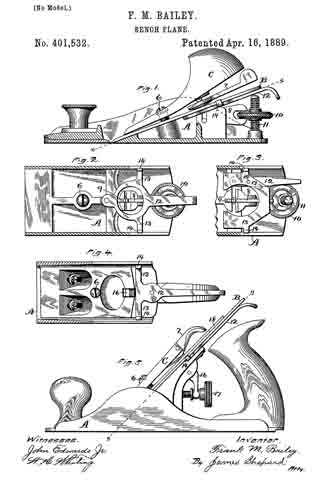
In the accompanying drawings, Figure 1 is vertical section of a plane-stock with a side elevation of the other parts of the plane. Fig. 2 is a sectional view of said plane-stock on the line x x of Fig. 1, with a face view of the parts below said line. Fig. 3 is a like view of a portion of a plane-stock and a modified form of laterally-adjusting lever. Fig. 4 is a like view showing still another form of laterally-adjusting lever, the plane of section being on the line y y of Fig. 5; and Fig. 5 is a side elevation of a complete plane, parts of which are illustrated in Fig. 4.
A designates the plane-stock provided with a cutting-bit, B, the same being held in position on its frog by means of the holding-screw 6, holding-cap C, and cam 7. In the form shown in Figs. 1, 2, and 3 the longitudinal adjusting-lever 8 is provided with teeth 9 at its forward end on its upper face, and is moved on its axis by the adjusting-nut 10, which travels up and down upon a screw-threaded post, 11. The central portion of the cutting-bit B, with this form of longitudinally-adjusting mechanism, is provided with a longitudinal series of transverse slots, into which the teeth 9 of the lever 8 engage for adjusting the cutting-bit longitudinally, all as in a well-known prior plane.
Upon the plane-stock underneath the cutting-bit, I pivot the laterally-adjusting lever 12, which lever is provided with laterally-extending arms 13 13, at the outer ends of each of which there is an upwardly-projecting lug, 14, for engagement with the two outer edges of the cutting-bit B. in Figs. 1 and 2 this lever is pivoted to the stock in a central position at a point below the teeth 9 of the longitudinally-adjusting lever, and the central portion of the lever 12 at this point is out away or provided with an opening, through which the engaging end of the lever 8 may project. The laterally-extending arms 13 and upwardly-projecting lugs 14 are formed integral with the lever 12. In the form shown in Fig. 3 these arms and lugs are formed of a separate piece from the lever 12, arranged to slide laterally, and are secured to said lever by the pin 15, so that the lateral movement of the lever 12 carries with it the upwardly-projecting lugs 14. In Figs. 4 and 5 the arms 13 and upwardly-projectings lugs 14 are also formed integral with the lever 13; but the pivot for said lever is located above said arm and lugs. The longitudinally-adjusting mechanism in this latter construction consists of an angle-lever, 16, and adjusting-screw 17, the upper end of the lever 16 taking into the cap-iron 18 of the cutting-bit, all as in a well-known prior construction.
In all of the various forms shown the two outer edges of the cutting-bit are received in between the upwardly-projecting lugs 14 14, so as to be engaged thereby, and the lever is pivoted to the stock underneath the cutter and vibrates laterally in a plane which is parallel to that of the cutting-bit. A lateral movement of the lever on its fulcrum causes the upwardly-projecting lugs to move laterally with said lever. One or the other of the upwardly-projecting lugs 14 (according to which direction the lever is moved) will engage with one edge of the cutting-bit and carry said bit laterally to adjust its lower edge, so as to be square with the stock, the general effect being the same as in lateral adjustments heretofore employed.
I do not claim, broadly, a lever pivoted to the stock underneath and parallel with the cutting-bit for rnoving it laterally; but, so far as I know, these laterally-adjusting levers, when directly engaging the cutting-bit, have been made to engage the cuting-bit at a point midway between its two edges.
I claim as my invention —
In a benoh-plane, the combination of the cutting-bit, a laterally-adjusting lever, the laterally-projecting arms and upwardly-projecting lugs moving laterally with said lever and adapted to engage the outer edges of the cutting-bit, substantially as described, and for the purpose specified.
FRANK M. BAILEY.
Witnesses:
H. S. WALTER,
F. N. STANLEY.