
No. 53,899 – Planes For Making Blind Slats (Enoch K. Thomas And Hans H. Andresen) (1866)
UNITED STATES PATENT OFFICE.
_________________
ENOCH K. THOMAS, OF ROCK ISLAND, ILLINOIS, AND HANS H. ANDRESEN, OF DAVENPORT, IOWA.
IMPROVEMENT IN PLANES FOR MAKING BLIND-SLATS.
_________________
Specification forming part of Letters Patent No. 53,899, dated April 10, 1866.
_________________
To all whom it may concern:
Be it known that I, ENOCH K. THOMAS, of Rock Island, Rock Island county, and State of Illinois, and HANS HEINRICH ANDRESEN, of Davenport, Scott county, State of Iowa, have invented a new and useful Plane for Making Window-Shade Slats; and we do hereby declare that the following is a full, clear, and exact description thereof, reference being had to the accompanying drawings, making a part of this specification, in which —
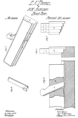
Figure 1 is a perspective view of a single-iron slat-plane. Fig. 2 is a perspective view of the cutter or plane-iron detached from the plane-stock. Fig. 3 is a sectional view, showing the mode of cutting slats from a piece of wood. Fig. 4 is a front end view of the single iron plane. Fig. 5 is a front end view of a plane-stock which is adapted for receiving three cutters.
Similar letters of reference indicate corresponding parts in the several figures.
The object of this invention is to produce slats for wooden window-shades of a uniform thickness and width by means of a plane which is so constructed that the slats pass freely through the plane-iron between the sole of the plane-stock and its bottom cutter without liability of becoming broken or otherwise injured, as will be hereinafter described.
To enable others skilled in the art to understand Our invention, we will describe its construction and operation.
The plane which we have represented in Figs. 1, 2, 3, and 4 of the drawings is intended for cutting one slat at a time from a piece of wood. The sole of this plane has three steps, a a’ a”. The intermediate step, a, is equal in width to the width of the slats which are produced, and the vertical surface of the step a2 is intended to form a side guide for the plane-stock in its forward movements over the piece of wood from which the strips or slats are cut.
The cutter or plane-iron B has a cutting-lip, b, on its lower end and a cutting-lip, c, formed on one side — that side which is nearest the step a. This plane-iron has an opening, d, through it, which should be equal in width to the width of the slats that are cut, so that as the slats that are severed from the piece of wood by the horizontal and vertical cutting-lips b c these slats will pass freely through the plane-iron without being materially bent out of a straight line, as shown in Fig. 3.
The plane-iron B is secured at the required pitch in its stock A by means of a wedge, C, in the usual manner of securing common plane-irons into their stocks, and the cutting-lip b projects below the sole of the stock a distance which is equal to the thickness desired for the slats.
It will be necessary to form a depression, e, just in rear of the cutter lf, so as to allow of the slats rising over this cutter; but as this cutter can be made quite thin, it will not be necessary to form much of a depression in the sole of the stock.
To obviate a gouging action of the cutting-lip b, which would cause the plane to work very hard and produce slats of an uniform thickness, the space between the cutting-edge of said lip and the lower end of the wedge C should not be greater than the required thickness ofthe slats. The space back of this point for a short distance may be increased, as above mentioned.
It will be seen from the above description of our plane or slat-cutter that the slat is held firmly down upon the surface of the piece of wood during the operation of producing it, and that the only elevation of the slat from such surface takes place at the cutter b, which must pass under the slat; but while this is the case the slat which is being cut will he held down in rear of said cutter, so that it cannot be broken or split.
We do not confine our invention to a single-iron plane for cutting or producing slats, as the stock may be adapted for receiving two, three, or more cutters, arranged as shown in Fig. 5, so that a number of slats can be cut at each forward movement of the plane over the piece of stuff.
It is obvious that this plane may be secured to a bench-vise or to any other object and the stuff moved over it instead of moving the plane by hand over the fixed stuff ; or, if desirable, the plane or the stuff from which the slats are cut may be moved by machinery without changing the principle of our invention. One great advantage of our invention is that we can cut slats from the side or edge of a board or log without the necessity of resawing and previously dressing the stuff, and this can be done with stuff of any thickness or width.
Were not our cutter provided with the two cutting-edges described, the splints or slats could not be cut from a bolt or plank of a greater thickness than the length of the cutting-edge of the cutter or plane-iron. This will be evident from an inspection of the drawings illustrating our mode of cutting strips or splints from a large bolt or log.
By arranging a series of cutters on a plane-stock, stepped as shown, we can, after having cut a series of splints from the bolt, bring two cutters into use, and after we have cut another series of splints by each of the two cutters we can bring into use a third cutter in connection with the two which are already brought into use, and so on, according to the number of steps and cutters provided on the plane-stock. To bring the different cutters into use a channel in the wood must be made tbr a succeeding cutter by a preceding cutter, as must be evident. Thus by our invention a series of splints may be cut at one time from a bolt which is of much greater thickness than the length of the edge of either of the cutters after channels adapted for the respective cutters are cut in the bolt.
Having thus described our invention, what we claim as new, and desire to secure by Letters Patent, is —
1. The construction of a cutter for producing slats with two cutting-edges and an opening through the shank of the cutter for the passage ofthe slats, substantially as described.
2. The combination of one or more slat-cutters, constructed substantially as described, with a plane-stock having its sole stepped substantially as set forth.
ENOCH K. THOMAS.
HANS HEINRICH ANDRESEN.
Witnesses:
HANS ARBAHR,
HANS KÜHAER.