No. 173,984 – Improvement In Bench-Planes (George F. Mortensen) (1876)

UNITED STATES PATENT OFFICE.
_________________
GEORGE F. MORTENSEN, OF NEW YORK, N. Y.
IMPROVEMENT IN BENCH-PLANES.
_________________
Specification forming part of Letters Patent No. 173,984, dated February 22, 1876; application filed August 20, 1875.
_________________
To all whom it may concern:
Be it known that I, GEORGE F. MORTENSEN, of the city, county, and State of New York, have invented a new and useful lmprovement in Bench-Planes, which improvement is fully set forth in the following specification, reference being had to the accompanying drawing, in which —
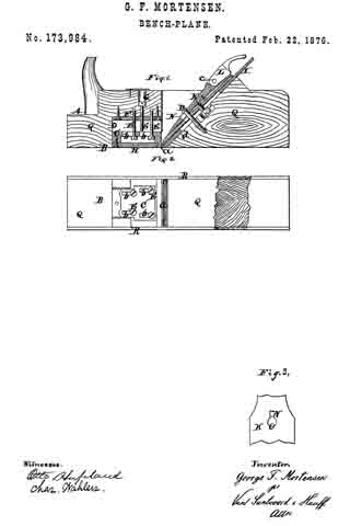
Figure 1 represents a longitudinal section of my improvement. Fig. 2 is a reverse plan view thereof, partly in section. Fig. 3 is a view of the slotted cap.
Similar letters indicate corresponding parts.
My invention relates to improvements in bench-planes, and as to one of its features particularly — to planes whose “stock” is made of wood.
That part of my invention relating to wooden planes consists in combining, with the “sole” thereof, an adjustable shoe for the purpose of regulating the “mouth” containing the plane-iron, the said shoe being made adjustable both vertically and horizontally through the medium of set-screws and of slots, through which the screws pass.
In the drawing, the letter A designates the stock of my plane, and B is the sole. C is the adjustable shoe, which is preferably made of metal, and is let into a cavity, D, immediately in front of the mouth a. The said shoe C is subjected to the action of set-screws E, which extend vertically into or through the stock A, to which end the stock is provided with a protecting-plate, F. The set-screws E extend both in an upward or downward direction. When the set-screws extend in both directions, as shown in Fig. 1, the head of the single screw, in this example extending downward, is preferably concealed in a socket, G, while, in order to conceal the heads of the upwardly-extending screws, and to impart to the shoe C a smooth surface, a face-plate, H, is affixed to the shoe. This face-plate is removed in Fig. 2, in order to expose the set-screws.
The set-screws pass through slots b, which, in the example shown in Fig. 1, are formed in the shoe C; but, if desired, the slots may be formed in the protecting-plate F.
By means of the set-screws E I am enabled to adjust the shoe C vertically toward the cavity D, for the purpose of preserving its level with the sole B, when the latter is “corrected,” while by providing the sole or the protecting-plate F with slots b, and passing the set-screws through the slots, the shoe may be adjusted to different positions horizontally, and particularly with respect to the mouth at, which, as is well known, becomes enlarged when the plane is corrected, owing to the slope of the bed d of the plane-iron.
The plane-iron I is made of the usual form, with an upper and a lower section, connected together by a screw, J.
K designates a cap, which, together with an eccentric or cam lever, L, constitutes a clamp for fixing the plane-iron on the bed d. The cap K is provided with a slot, N, which has at one end a hole, O, (see Fig. 3,) equal in diameter to that of a stud, P, formed by the head of a screw, which is fastened to the bed d, so that by moving the cap K to such a position that the stud occupies the narrow part of the slot, the cap is rendered capable of tilting under the stud P.
The cam-lever L turns on a pivot, c, and is fastened on the upper end of the cap K.
When the cam-lever is turned to the position shown in the drawing, it bears on the upper portion of the top section of the plane-iron I, thereby raising the upper end of the cap K, while by the tilting of the cap thus occasioned its lower end is caused to bear on the corresponding portion of said top section of the plane-iron, and by this arrangement the iron may be readily adjusted and firmly held in any position.
The stock A of my plane is made in two divisions, Q, (or more than two, if required,)
which are connected together by side strips or cheeks R. By this construction of the stock, far greater strength is imparted to it than when made in a single piece, while the parts of the stock, moreover, being very readily put together, the whole can be furnished at a comparitively small cost.
What I claim as new, end desire to secure by Letters Patent, is —
The combination, with the stock of a bench-plane, of a, recessed shoe, C, with a, detachable face-plate, H, the set-screws E E E and slots b, all constructed to operate substantially as described.
In testimony that I claim the foregoing I have hereunto set my hand and seal this 17th day of August, 1875.
GEORGE F. MORTENSEN. [L. S.]
Witnesses:
E. F. KASTENHUBER,
FRANCIS FORBES.


