| PLEASE NOTE: The images presented on this page are of low resolution and, as a result, will not print out very well. If you wish to have higher resolution files then you may purchase them for only $2.95 per patent by using the "Buy Now" button below. All purchases are via PayPal. These files have all been cleaned up and digitally enhanced and are therefore suitable for printing, publication or framing. Each zip package contains all the images below (some packages may contain more), and purchased files can be downloaded immediately. |
UNITED STATES PATENT OFFICE.
_________________
CHARLES G. MILLER, OF NEW BRITAIN, CONNECTICUT, ASSIGNOR TO STANLEY RULE AND LEVEL COMPANY, OF SAME PLACE.
IMPROVEMENT IN TONGUING AND GROOVING PLANES.
_________________
Specification forming part of Letters Patent No. 181,357, dated August 22, 1876; application filed July 17, 1876.
_________________
To all whom it may concern:
Be it known that I, CHARLES G. MILLER, of New Britain, in the county of Hartford and State of Connecticut, have invented an Improvement in Tonguing and Grooving Planes, of which the following is a specfication:
In Letters Patent No. 165,355, granted July 6, 1875, a plane is shown with two cutters and an intermediate groove for the tongue that is left upon the edge of the piece of wood, and there is a guide that can be turned around or reversed when the plane is to be used for grooving. In this plane there is but one guide for the face of the board, the guide having two sides, one of which comes against the board in planing the tongue, and the other comes against the face of the board in planing the groove after the guide has been swung around for that purpose.
My present improvement consists in the combination, with a tonguing and grooving plane and stationary guide, of a second guide that is movable in a plane parallel to the face of the stationary guide, so that the plane can be used in the ordinary manner for tonguing the edge of the board, the movable guide remaining out of the way while so doing, and upon depressing the movable guide it changes the tool into a grooving-plane, so that only one cutter is used to form the groove.
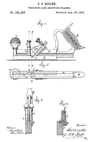
In the drawing, Figure 1 is a side view of the plane. Fig. 2 is an inverted plan. Fig. 3 is a section at x x, with the movable guide or fence out of use; and Fig. 4 is a section at the line y y, representing the plane as in use for forming a groove.
The stock a, handle b, and knob c, are of any usual or desired size or character. The two cutters e and f are also constructed in the ordinary way and clamped, preferably by levers and thumb-screws. The stationary guide or fence It is upon the plane-stock, and I runs against the face of the board in the ordinary manner when the plane is being used to form a tongue. The cutter e is of the same width as the tongue ; hence to use said cutter in forming a groove it is only necessary to introduce a movable fence or guide at the proper distance from the cutter to enable the work-man to use the plane for grooving the wood for the reception of the tongue.
I accomplish this object by using the movable fence or guide i that moves in a plane parallel with the face of the stationary guide k.
I have shown this guide i as sliding vertically in a narrow channel made through the plane-stock, and the guide i is attached at one side of a headed stud, k’, that passes through the hollow stud l upon the plane-stock.
The portion of the stock that forms the bed for the cutters is slotted or channeled to allow of the movement of this guide ; so, also, is the stud upon which the knob e is placed. When the guide fi is pushed down into position shown in Fig. 4, the plane is adapted to grooving, and when said guide is not needed, it is moved in the plane parallel to the face of the board so as to be out of the way when using the plane for forming the tongue. This guide i might be pivoted at one end and swing in the same plane of motion as aforesaid, in a manner similar to a knife-blade.
I claim as my invention —
The combination, with a tonguing-plane, having stock a, cutters e and f, and guide k, of the second guide or fence i, moving in a plane parallel to the face of the stationary guide, substantially as set forth.
Signed by me this 7th day of July, A. D.
1876.
C. G. MILLER.
Witnesses:
JULIUS H. PEASE,
ISAAC PORTER.


