No. 180,050 – Improvement In Bench-Planes (William Montgomery) (1876)

UNITED STATES PATENT OFFICE.
_________________
WILLIAM MONTGOMERY, OF AMITY, PENNSYLVANIA.
IMPROVEMENT IN BENCH-PLANES.
_________________
Specification forming part of Letters Patent No. 180,050, dated July 18, 1876; application filed April 27, 1876.
_________________
To all whom it may concern:
Be it known that I, WILLIAM MONTGOMERY, of Amity, in the county of Washington and State of Pennstylvania, have invented Improvements in Bench-Planes; and I do hereby declare that the following is a full, clear, and exact description of the same, reference being had to the accompanying drawing, which forms part of this specification.
My invention relates to a new combination of devices for adjusting and clamping the blade or plane iron in the stock of the plane; and it consists in the combination of devices employed as hereinafter more fully set forth.
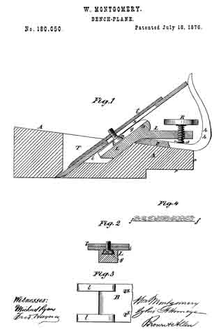
Figure 1 in the accompanying drawing, represents a vertical longitudinal section through my improved plane. Fig. 2 is a section through the plane irons and attachments thereof on the line x x. Fig. 3 is a top view of the bed-plate, to which the clamping-lever, which secures the irons in the plane-stock, is pivoted. Fig. 4 is a diagram illustrating the manner in which the grain of the wood runs in relation to the face of the plane.
A is the stock, which may be made of wood or metal. The said stock is thinner, measured vertically, at the rear end or heel than at the forward end, and at the rear end the stock is provided with a projection, p, which supports inpart the handle n. In cutting the plane-stock to the wedge form the grain of the wood is cut obliquely across, as shown in Fig. 4, in which the dotted lines represent the grain of the wood, and the line f f represents the face of the plane. The bed-plate B, shown in Fig. 3, and in section in Fig. 1, is attached to the top of the plane-stock A, at the back of the throat T of said stock, the attachment being made by screws x. The bed-plate B has at its front end lugs l, Fig. 3, to which is pivoted, by a screw-bolt, or in any other suitable manner, the bent lever L, the said bed-plate being cut away between the said lugs to make room for said lever L, and the tops of said lugs being rounded off, to allow the plane-irons i t to retreat far enough at the top to allow the insertion of a wedge under them at the bottom. The front part of the lever L passes down into the throat T of the plane, a recess, r, being formed in the back of said throat for the reception of the said front part of said lever, and the rear part of said lever passes backward over the top of the bed-plate, at the rear of the said throat T. In the rear part of said lever is fitted a thumb-screw, R, and in the front part of said lever is formed a dovetail-groove, g, shown in section in Fig. 2.
The head of the screw m, which holds the top iron on the cutting-iron of the plane, is made in the form of a frustum of a cone, and of dimensions to adapt it to the dovetail groove g in the front part of the lever L. The point of the thumb-screw R rests in a notched saddle, S, either on the handle h, the bed-plate B, or the plane-stock A, in various kinds of planes, and the said screw may fit a female screw in the rear end of the lever L, or it may fit the thread of a nut swiveled to the said lever. The half-handle h is formed in one piece with the bed-plate B, as shown in Fig. 1, when the plane-stock A is made of wood; but when the plane-stock is made of metal the bed-plate B may be dispensed with, and the lugs l of the same, and the handle h, may be cast in one piece with said stock. And when a jack-handle is used, it is attached to the stock, and not to the bed-plate B. Also, in long-faced planes the projection p, which supports the rear of the handle in short-faced planes, is omitted, there being space enough for the support of said handle without the projection. The cutting iron i and top iron t are fitted into the throat, as shown in Fig. 1, the top iron being held upon the cutting-iron by the screw m, which passes through the slot n, in the cutting-iron, and screws into the top iron in the usual manner.
The adjustment and clamping of the irons i and t are performed as follows: The top iron t is placed in its proper position on the cutting-iron i, and is fastened there by the screw m. The irons are then placed in the throat T of the stock A, the head of the screw in passing down into the groove g of the lever L. The screw R is then turned down, and, its point being prevented from advancing, the hinder part of the lever L is forced upward. This forces the lower part of the lever L downward and rearward, and draws backward and downward the screw m, the head of which is engaged in the groove g of the said lever, and the opposite end of which is engaged in the female screw of the top iron, t. The plane-irons are thus firmly pressed against the lower part of the throat of the plane-stock, and that part of the lever L in front of the pivot of said lever, which pressure securely clamps the irons in the plane-stock.
The head of the screw m might be made of proper form to engage a groove of rectangular cross-section in the lower part of the lever L; but I prefer the dovetail groove and the corresponding shape of head for the said screw, because this form gives a wedging action, which holds the irons powerfully without excessive strain on the thumb-screw R.
A cheap, easy-running, and durable plane is thus produced, in which the handle is brought down nearer the work than in planes heretofore used, and hence the muscular power of the operator is more efficiently applied.
I claim —
The combination of the stock A, having projection p, with the pivoted lever L, provided with a dovetail groove in its face, adjusting-screw R, notched saddle S, bed-plate and handle B h, and screw m, all constructed to operate as shown and described, and for the purpose specified.
WILLIAM MONTGOMERY.
Witnesses:
B. F. MONTGOMERY,
JAMES B. MONTGOMERY.


