No. 185,442 – Improvement In Match-Planes (Porter A. Gladwin) (1876)
UNITED STATES PATENT OFFICE.
_________________
PORTER A. GLADWIN, OF CHELSEA, MASSACHUSETTS.
IMPROVEMENT IN MATCH-PLANES.
_________________
Specification forming part of Letters Patent No. 185,442, dated December 19, 1876; application filed November 6, 1876.
_________________
To all whom it may concern:
Be it known that I, PORTER A. GLADWIN, of Chelsea, in the county of Suffolk and State of Massachusetts, have invented certain Improvements in Match-Planes, of which the following is a full, clear, and exact description, reference being had to the accompanying drawings, making part of this specification, in which —
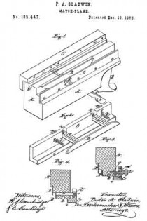
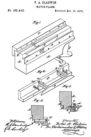
Figure 1 is a perspective view of my match-plane inverted. Fig. 2 is a perspective view of the two movable gages connected together and detached from the plane. Figs. 3 and 4 are transverse vertical sections.
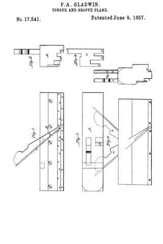
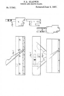
My present invention relates to certain improvements in match-planes for which Letters Patent of the United States No. 17,541 were granted to me June 9, 1857.
The stock of the plane referred to was constructed so as to receive and hold a double iron-one portion for tonguing and the other for grooving–two stationary gages being employed in connection with this double iron; but on account of these gages being stationary only one thickness of material could be matched with a single plane, and consequently a number of these tools were required to match boards of different thicknesses.
My invention has for its object to provide a single match-plane, which can be so adjusted as to adapt it for boards of various thicknesses; and consists in a pair of movable gages, in combination with a stock provided with both a tonguing and a grooving iron.
My invention also consists in so connecting or coupling these gages that they may be moved simultaneously in the same direction, in order thereby to insure the perfect matching of two boards of the same thickness.
My invention furthermore consists. in making one of the gages adjustable independently of the other, in order that the relative position of one gage may be slightly changed with respect to that of the other, whereby the tongue and groove may be so located that the surfaces of the two boards to be matched will lie flush with each other.
To enable others skilled in the art to understand and use my invention, I will proceed to l describe the manner in which I have carried it out.
In the said drawings, A represents the stock of my improved plane, which is provided with a handle, b, its bottom being of the form seen. In the throat of the stock is secured, by means of a wedge, a double-edged tonguing-iron, c, a double-edged grooving-iron, d, being also secured within the stock by a wedge, e, a throat, 5, being formed in a plate, B, screwed to one side of the stock, through which the iron d passes.
On the bottom of the stock A, opposite to that to which the plate B is screwed, slides a longitudinal gage, G, of L shape in cross-section, and provided with a metal facing, i, the distance of which from the edge of the groove k in the stock A is regulated by two thumb-screws, l l, which pass through plates m m, let into the side of the gage, and enter nuts p, set into the stock A, as seen in Fig. 3, each screw being held in place within the gage by a collar, q; and by means of these screws the position of the gage with respect to the groove in the tonguing-iron c may be varied as desired for boards of different thickness.
The part of the plane which cuts the groove is provided with a movable gage, D, by which the distance of the groove from the edge of the board may be varied according to its thickness. This gage D consists of a plate, which is connected or coupled with the tonguing-gage C by two slotted bars, r r, passing through the stock, the bars r r, which project from the side of the gage D, being secured to the gage C by screws t, which admit of the distance between the gages being slightly varied, as desired; and when these screws are clamped or tightened the gages are rigidly coupled or secured together, so as to move simultaneously in the same direction when operated by the thumb-screws l l. By rigidly connecting the two gages C D, so that they will move in common, the distance of the gage C from the nearest edge of the groove in the tonguing-iron c will be exactly equal to the distance of the gage D from the side of the grooving-iron d nearest to it, by which means the location of the groove in one board will exactly correspond with the location of the tongue of the other board to be matched therewith, so that when the two boards are united their surfaces will lie exactly flush with each other.
The object of the slight independent adjustment of the gages by means of the clamping-screws t t to provide a means whereby their original relative position may be restored with perfect accuracy in the event of their becoming accidentally displaced, or the distance between them becoming changed by wear. The gage D, instead of extending along a portion only of the stock A and fitting into a recess, as shown, may extend the entire length of the stock, if desired. Instead of the gages being rigidly connected, so as to move simultaneously, they may be moved toward or from their respective irons by separate and independent screws or other devices; but I prefer to connect them, as much inconvenience and delay is thereby avoided, and the construction is simplified.
By the employment of adjustable gages boards of any thickness within the limits of the movement of the gages may be matched with a single plane; whereas, were the gages stationary, as described in my aforesaid Letters Patent No. 17,541, a different plane would be required for every board of a different thickness, and consequently the expense of a great number of planes is avoided, together with the trouble of transporting them from place to place, and the labor of grinding and keeping them in order while much space is also economized.
What I claim as my invention, and desire to secure by Letters Patent, is —
1. The movable gages C D, in combination with a plane-stock, A, provided with tonguing and grooving irons c d, substantially as and for the purpose set forth.
2. The gages C D, made adjustable independently of each other by the slotted bars r r and screws t t, in combination with the stock A, provided with tonguing and grooving irons, substantially as and for the purpose set forth.
Witness my hand this 24th day of February, 1876.
PORTER A. GLADWIN.
In presence of —
N. W. STEARNS,
P. E. TESCHEMACHER.

