No. 178,256 – Improvement In Carpenters’ Planes (Samuel Williams) (1876)

UNITED STATES PATENT OFFICE.
_________________
SAMUEL WILLIAMS, OF COLUMBUS, OHIO.
IMPROVEMENT IN CARPENTERS’ PLANES.
_________________
Specification forming part of Letters Patent No. 178,256, dated June 6, 1876; application filed March 15, 1876.
_________________
To all whom it may concern:
Be it known that I, SAMUEL WILLIAMS, of Columbus, in the county of Franklin and State of Ohio, have invented certain new and useful Improvements in Carpenters’ Planes; and I do hereby declare that the following is a full, clear, and exact description thereof, which will enable others skilled in the art to which it appertains to make and use the same, reference being had to the accompanying drawings, and to the letters of reference marked thereon, which form a part of this specification.
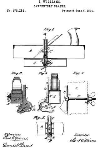
In the accompanying drawings, Figure 1 is a side elevation of a plane with my improvement attached thereto. Fig. 2 is a vertical transverse section of the same on the line x x, Fig. 1. Fig. 3 is an end view, showing the motion of the guide in dotted line. Fig. 4 is a full-sized view of the clutch-bolt and thumb-screw. Fig. 5 shows a detached modification.
My invention consists of certain novel combinations and arrangements of devices for a simple and efficient bevel-guide for planes, the details of which will be fully understood by the following description:
ln the accompanying drawings, A is a plane-stock, with a groove, B, out in each side, to receive the adjustable slide C, which is cast in the same piece with the male part F of the hinge. This slide has a rib, c, which fits the groove B of the plane, in order to prevent the slide from swinging, and thus throwing the bevel-guide out of place. The guide D is attached to the hinge-piece E, which is very strong, and has a slot with broad bearing-sun faces, to grasp the male part F of the hinge, and hold the same firmly in place. This hinge has a central pivot, G, and a set-screw, H, which passes through the curved slot I, Fig. 2, in order to adjust the bevel-guide to any desired angle. A clutch-bolt, K, passes through the plane-stock A, as shown in Fig. 4, and has one end provided with the clutch K’, to grasp the slide C, while the other end is provided with a thumb-screw or nut, L, and washer, M, for fastening the guide to the plane.
The hinge may be graduated in an arc, so as to set the guide D at any desired angle, as is well understood.
Instead of the clutch- bolt K, an arched plate, N, with a set-screw, O, may be used; but I prefer the clutch-bolt shown in Fig. 4.
If necessary with long planes, two clutch-bolts and two hinges may be used to hold the guide more securely in place.
This guide is very simple, and yet strong and durable, and it is very convenient of adjustment, and may be easily changed from one side of the plane to the other, and thus enable the workman to plane cross-grained stuff, and also prevent the uneven wear of the bit.
Having thus described my invention, I claim —
The slide C, provided with the rib c, in combination with the bolt K, bevel-guide D, and plane-stock A, substantially as and for the purposes set forth.
In testimony that I claim the foregoing as my own I affix my signature in presence of two witnesses.
SAML. WILLIAMS.
Witnesses:
DANIEL BREED,
S. E. CARPENTER.


